Loss of Detailed Balance in Equilibrium due to Partial Quantum Decoherence: A Quantum Graph Analogue
Abstract
We explore the physics of quantum systems that suffer from partial decoherence, in the intermediate range between coherent quantum evolution and incoherent classical physics. It has been predicted that new physics and technology are enabled in this intermediate regime. In particular we explore the asymmetric transmission through an Aharonov-Bohm (AB) ring that supports a 3:1 asymmetry in transmission times, augmented with de-phasing features that act preferentially on the longer-lingering quantum waves. Such a device is realized as a microwave analogue quantum graph utilizing a gyrator to create the 3:1 transmission time delay asymmetry, along with both homogeneous and localized losses to mimic the effects of de-phasing in the analogous mesoscopic electron system. Measurements and simulations of this device demonstrate the required non-reciprocal transmission time delay, as well as an asymmetry in transmission probability. The measurements and simulations are performed in both the frequency domain, and in the time domain using wave packets. We demonstrate asymmetric transmission through the AB-ring graph as a function of loss/de-phasing in both simulation and experiment, in both the frequency- and time-domains, and compare to expectations for the corresponding quantum system. The results are consistent with the hypothesis that the transmission asymmetry and loss of detailed balance is an equilibrium property of the analogous mesoscopic quantum graph.
There is a deep disparity between the quantum mechanical and classical perspectives on physical laws. Our experience with the classical world is dominated by equations of motion that include loss, dissipation, and friction, explicitly breaking time-reversal invariance, and describing phenomena involving large numbers of interacting particles, creating a perception of the “arrow of time” [1, 2]. At the microscopic scale we know that the laws of quantum mechanics are time-reversal invariant, and isolated systems are described by unitary time evolution of the quantum state. This poses the question: how do the laws of quantum mechanics segue into those of classical mechanics as one admits stronger interactions with other degrees of freedom? Such questions have been addressed in the fields of fundamental quantum mechanics [3, 4, 5, 6], quantum chaos [7], quantum statistical mechanics [1], and mesoscopic physics [8, 9], among others. To give further insight into these issues, here we explore the properties of systems that are intermediate in character between the microscopic realm of unitary quantum evolution and the macroscopic world dominated by the incoherent dynamics described by classical physics.
A related question is whether or not there is new physics to explore in the regime between pure quantum evolution, and classical physics? Can systems described by a mixture of quantum and classical properties show qualitatively new phenomena that are not anticipated by the properties of systems in either limit? More specifically, can a finite degree of quantum ‘de-phasing’ be harnessed to perform a new task that is not possible in the fully quantum or fully classical limits? In terms of applications, coupling a quantum system to additional degrees of freedom can be used to accomplish fast reset of qubits,[10] for example. However, it is interesting to see if qualitatively new phenomena can be discovered and exploited in this regime.
There has been long-sustained interest in preparing materials and devices that explicitly break time-reversal invariance (TRI) to create non-reciprocal transport for electrons between equivalent contacts [8, 9], for example. Many proposals to create non-reciprocal transport are inspired by Maxwell demons,[11, 12] thermally-driven ratchets,[13] non-centro-symmetric materials,[14] and efforts to violate detailed balance in thermal radiation [15, 16]. Systems with nonlinearity have been utilized to demonstrate asymmetric transport[17, 18]. One approach to selectively transferring electrons is to create wavefunction interferometers that preferentially pass matter waves moving in one direction but not the other, and such devices require breaking of time-reversal invariance [19, 20]. In particular, the Aharonov-Bohm matter-wave interferometer, augmented with decoherence to induce non-reciprocity,[21] has been proposed as one possible setting for this type of device.
The Aharonov–Bohm (AB) effect is a quantum mechanical phenomenon in which an electrically charged particle of charge is affected by an electromagnetic potential (through the vector potential A) in the absence of a magnetic or electric field at the location of the particle [22]. This effect gives rise to a type of “action at a distance” in which a particle can be affected by electromagnetic fields even if it does not experience them directly. The traditional setting for the AB effect is a finite region of space containing non-zero magnetic flux surrounded by a field-free region. A beam of charged particles is sent through the field-free region in a ring geometry that fully incorporates the region of finite flux within the ring. The charges show interferometric properties arising from a quantum phase shift upon traversing each branch of the ring. Upon recombination, parts of the wave packet that pass through different branches of the ring create interference that depends on , where is the flux quantum for the charges, and is Planck’s constant.
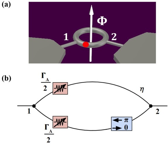
In Refs. [19, 23, 20, 24], the authors consider an Aharonov-Bohm (AB) ring in a mesoscopic conducting sample that suffers from a certain degree of “de-phasing” in electron transport. Specifically, they consider a single-channel, 2-terminal AB ring enclosing a DC magnetic flux (as described above). Fig. 1 shows the schematic of the proposed mesoscopic Aharonov–Bohm ring, along with a schematic of the functionally equivalent microwave graph that we consider in this paper. The non-zero magnetic flux and bond lengths are chosen such that the left-going and right-going wavepackets behave differently. A quantum wave propagating through the device from left to right, say, will split into two parts at the left combiner. Along each of these paths, the respective wave will accumulate a phase. In order for the waves to successfully recombine at the other end, they must be in phase with each other, and hence the net phase difference accumulated must be . The magnetic flux and path lengths are chosen to achieve this condition. The device is designed such that a quantum wave propagating in the opposite direction will split at the right combiner, but will accumulate an additional phase difference of between the wave in the upper arm and the wave in the lower arm. This results in destructive interference between these waves at the left combiner, causing them to reflect and travel back through the ring. When the waves meet again at the right combiner, they have accumulated a net phase difference of , causing them to again destructively interfere and reflect back around the ring. This time, when the waves meet at the left combiner, they will have accumulated a net phase difference of . Hence, the waves will finally be in phase and will be able to coherently combine and exit the ring.
As a result, the electrons emitted from one source into the ring would experience a three times greater transmission time compared to the electrons injected from the other source, due to the need to acquire a phase shift by means of multiple reflections in the ring. Furthermore, it has been proposed [23, 9, 21] that a finite degree of quantum dephasing can enable asymmetric transmission through the Aharonov–Bohm ring structure. Dephasing has the effect of partially destroying the coherent flow of the electrons, such that they lose memory of which direction they were initially injected, and thus the dephased electrons exit the device with equal likelihood in either direction, meaning that interference effects alone do not dictate their behavior. This creates an asymmetry due to the non-reciprocal dwell times in the ring and therefore the selective action of a de-phasing center on the long-lingering wave packets. The net result is asymmetric transmission of electrons from one equivalent reservoir to another in the absence of an externally-applied voltage bias.
In addition to the explicit proposals made in Refs. [19, 23, 24], a few other works have hinted at this asymmetry effect. The work of Entin-Wohlman, et al. essentially considers a quantum ring subjected to an external magnetic field and suffering partial de-phasing in electron transport around the graph. They calculate that this results in a loss of detailed balance in equilibrium, and the creation of a net current between two points in the ring [25]. A cold atom version of a dissipative AB-ring in momentum space, roughly similar to that described here, has been demonstrated [26]. However, this approach requires precise control of phase shifts in momentum space and lacks the direct physical generality of the present approach.
In this paper, our objective is to demonstrate non-reciprocal transmission in the presence of finite de-phasing, in the regime between purely quantum and fully classical physics,[9] through a microwave graph analogue of the Aharonov–Bohm ring. There is a long history of using microwave circuits and resonant microwave billiards to emulate quantum systems. Quantum billiards are simulated using equivalent microwave resonators, where the analogy between the Schrodinger equation for the wavefunction and the electromagnetic Helmholtz equation for one component of electric field is particularly clear in two-dimensions [27, 28, 29, 30, 31, 32, 33]. Similarly, the analogy between solutions to the Schrodinger equation on multi-connected molecules [34] and the wave equation on networks of microwave graphs has been noted [35]. It was also shown that there is a direct analogy between the Poynting vector for energy flow in the two-dimensional electromagnetic cavity and the probability current in the corresponding quantum system [36]. In Ref. [37] it was experimentally demonstrated that the uniform attenuation of the microwave cavity (parameterized as the dimensionless quantity , where , is angular frequency, is the area of the billiard, and is the typical quality factor of the resonant modes) was directly proportional to the dimensionless de-phasing rate that governs the statistics of the scattering (S) matrix and conductance in the corresponding mesoscopic billiard [38], as over a wide range of microwave loss. Here we consider quasi-one-dimensional microwave network analogues of quantum graphs that simulate corresponding few-channel mesoscopic conducting quantum systems. Quantum graphs are one-dimensional metric graphs with complex topology that support excitations described by the Schrodinger operator [39, 40] that can be used to describe quantum transport through a variety of structures, including molecules [34, 41], quantum wires,[42, 43] disordered two-dimensional quantum dots [44, 45, 43], etc.
We introduce a two-terminal, single-channel microwave graph realization of the mesoscopic Aharonov–Bohm ring, and study its scattering properties in both the frequency domain and the time domain. Microwave graphs have been used to investigate many aspects of quantum scattering theory, including statistics of the Wigner reaction matrix (analogous to electromagnetic impedance)[35], topological edge invariants,[46] deviations from the predictions of random matrix theory,[47] etc. The graph in Fig. 1(b) satisfies all of the conditions for displaying asymmetric transmission, including broken time-reversal invariance, a sub-unitary scattering matrix, and a gyrator which produces a broadband constant phase shift for waves going in one direction [23]. The microwave graph consists of a coaxial cable structure that supports a single mode of propagation for microwave frequencies below the cutoff of higher-order modes, which is well beyond our operating frequency range [35]. In the frequency domain, we measure the scattering ()-matrix between ports 1 and 2 shown in Fig. 1(b), and calculate the complex transmission time delay [48, 49, 50, 20, 51, 52] for waves travelling in both directions. We demonstrate that the forward and backward transmission time delays have a 3:1 ratio in a broad range of frequency, which establishes the first condition for asymmetric transmission. We also introduce a localized loss (analogous to a dephasing center in mesoscopic transport [37]) in the ring graph, and adjust the transmission coefficients by varying the attenuation of that object. We demonstrate the dependence of asymmetric transmission on the de-phasing (loss) rate through the attenuation variation. In the time domain, we measure the transmission time delays of short pulse excitations, approximating the behavior of electron wave packets, and verify the 3:1 ratio of the transmission time delays in both directions. The amplitudes of the pulses also directly demonstrate the asymmetric transmission properties. This establishes the analogy between mesoscopic and microwave Aharonov–Bohm rings, and leads to the surprising result that a net transmission asymmetry of wave flow can be created by means of partial de-phasing. Remarkably, all of these results hold for both coherent and incoherent sources of microwave signals.
The outline of the paper is as follows. We first present simulations of the AB-ring graph and demonstrate the properties required to achieve asymmetric transmission. A number of complications are added to the simulations to represent the experimental situation, and the key properties are shown to survive. Next we present the experimental realization of the AB-ring microwave graph, and discuss measurements of the scattering matrix and time delays in both the frequency and time domains, and find good consistency with the simulations. Finally we present results on the transmission asymmetry through the graph in experiment, and compare to expectations based on simulations and mesoscopic physics.
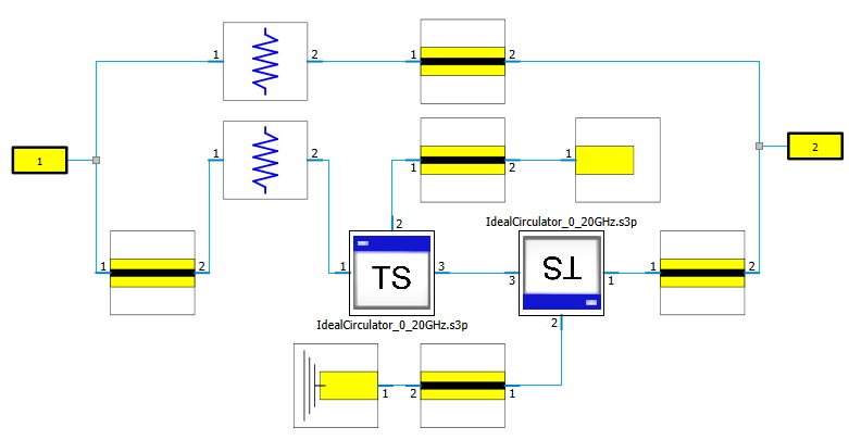
Simulations We first simulate the non-reciprocal transport effect of the AB-ring microwave graph in CST Microwave Studio. In particular we use a circuit modeling package to create a faithful model of the microwave quantum graph (see Methods and Fig. 7). We implement the complete circuit shown in Fig. 1(b) with equal electrical lengths for the upper and lower bonds.
Frequency domain Figure 2(a) shows the simulation comparison between the real part of the transmission time delay for the two directions, demonstrating the required 3:1 ratio, modulo oscillations associated with the shape resonances of the microwave graph [52]. Fig. 2(b) shows the transmission magnitudes and through the microwave AB-graph under several different attenuation settings. When the lumped attenuation is 0 Nepers and there are no uniform losses, i.e. no loss in the entire system and a unitary S-matrix, the two transmission paths have identical transmission magnitude as a function of frequency. As the lumped attenuation increases, significant differences begin to show up between the two transmission amplitudes.
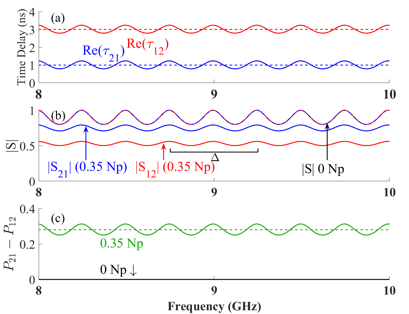
The asymmetric transmission behavior of the ring graph at each frequency can be quantified as the transmission probability difference: . Note that is bounded between 0 and 1, and is frequency dependent in general. If there is no asymmetric transmission then is equal to 0, while a non-zero value implies some degree of asymmetric transmission. Fig. 2(c) shows as a function of frequency for the Np attenuation case, revealing a frequency-averaged value (dashed green line) above 0.25.
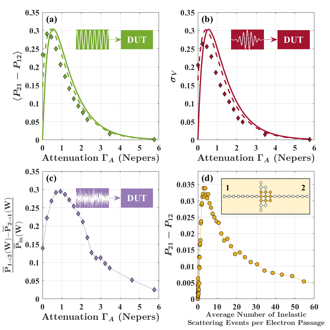
To explore the asymmetric transmission further, Fig. 3(a) shows as a function of lumped attenuation for the model graph. Due to the periodic wiggles arising from the shape resonances of the ring graph, we perform an average of over a range of frequencies corresponding to one period of the shape resonances GHz, and designate it as . The frequency averaged transmission asymmetry shows a non-monotonic bell shaped behavior as the lumped attenuation increases, which agrees with expectations from mesoscopic theory (see Fig. 3(d)). The mesoscopic calculation shows a non-monotonic dependence of asymmetric left/right transmission probability as a function of the average number of inelastic scattering events per passage based on a model of the quantum mesoscopic system shown in the inset [21, 9]. Plotting the lumped attenuation in units of Nepers (a decay of amplitude) is roughly analogous to the number of inelastic scattering events per passage of the wavepacket through the device (see Supp. Mat.). In the unitary evolution (zero attenuation) case, there is symmetric transmission due to the purely coherent properties of the system. At large de-coherence (attenuation) rates, the scattering events are so frequent that they destroy any bias for the electrons to follow a particular direction through the device. Only in the intermediate de-coherence case does the combination of coherent transport, along with a finite degree of de-coherence acting asymmetrically, result in a net transmission asymmetry though the device. This unique state is not observed in either the purely quantum or purely classical limits, but is a unique feature of quantum systems suffering partial decoherence [9]. Similar results on asymmetric transport of a Bose-Einstein condensate through an AB-ring analogue in cold atoms, as a function of loss rate (analogous the the attenuation used here), shows the same qualitative dependence as those in Fig. 3 [26].
We have also simulated the case where both uniform attenuation and lumped variable attenuation are present in the AB-ring microwave graph. We have chosen a value of uniform attenuation that approximately matches that used in the experiments described below. The resulting transmission asymmetry vs. lumped attenuation is also shown in Fig. 3(a) as a dashed line. The main difference is that uniform attenuation effectively establishes a finite degree of de-phasing, creating a finite amount of asymmetric transmission even with zero lumped attenuation.
Time domain Time-domain simulations have been performed with the model AB-ring graph shown in Fig. 7 (see Methods). Gaussian wave packets with 1 ns width are injected into the graph from each port. The output pulses show the expected 3:1 asymmetry in time delay upon going through the graph, as shown in Fig. 8. To quantify the transmission probability difference in the time-domain, we form the quantity , where and are the voltage amplitudes of the transmitted pulses in the simulations and is the amplitude of the incident pulse. Fig. 3(b) shows as a function of the lumped attenuation (solid line). As the lumped attenuation increases the transmitted wavepackets first show an increasingly asymmetric transmission probability. However, beyond about 1/2 Np of attenuation the wavepackets show reduced transmission asymmetry. The addition of uniform loss serves to shift the curve (dashed line), just as with the frequency domain simulations in Fig. 3(a).
These simulation results of the microwave AB-ring graph in both the frequency- and time-domains establish the basic properties of asymmetric transmission in analogy with mesoscopic AB-rings.
Experiment In the proposed non-reciprocal device, the Aharonov–Bohm ring uses magnetic flux to produce non-reciprocal transmission times in a simple electron interferometer. In order to mimic that effect, we use a microwave gyrator [53, 54, 55] to create a uni-directional phase shift in a microwave network (see Methods and Figs. 9 and 10).
The losses in the microwave graph arise from two sources. There exists roughly uniform attenuation of the microwave signals associated with the insertion loss of the coaxial cables, circulators, phase trimmers, microwave tees, adapters, and terminations. The attenuation of the coaxial cables used here, which dominates the uniform attenuation in the circuit, has been characterized in Appendix B of Ref. [52]. The second source of loss is associated with the variable lumped (localized absorbing channels) attenuators , shown schematically in Fig. 1(b). Both of these loss sources are assumed to contribute their own rates of equivalent de-phasing in a mesoscopic AB-ring, as justified by the simulations. In the experiments both types of loss in the microwave graph will be considered. Note that in all comparisons of microwave data and mesoscopic theory we treat the independent variables frequency and energy as interchangeable.
Frequency domain experiments We measure the scattering ()-matrix of the Aharonov–Bohm ring microwave graph shown in Fig. 11 (with approximately uniform attenuation only) from 7 to 12.4 GHz, (see Methods) and plot the results in Fig. 4. The periodic wiggles in the plot come from the shape resonances of the graph, which have been thoroughly studied in Refs. [52] and [56], and discussed for the simulations. The periodicity of the shape resonances depends on the total circumferential length of the graph m, which corresponds to a repetition frequency of GHz. Note that waves propagating anti-clockwise around the AB-ring satisfy the ordinary shape resonance conditions, , with . However, waves travelling clockwise around the AB-ring suffer an additional phase shift upon passage through the gyrator, resulting in a different resonance condition, , with , creating a series of modes that begin at GHz, and then alternate with the anti-clockwise modes as a function of frequency, consistent with the periodicity shown in Fig. 4. This creates two distinct sets of S-matrix poles and zeros for the modes of the AB-ring graph (see Supp. Mat.).
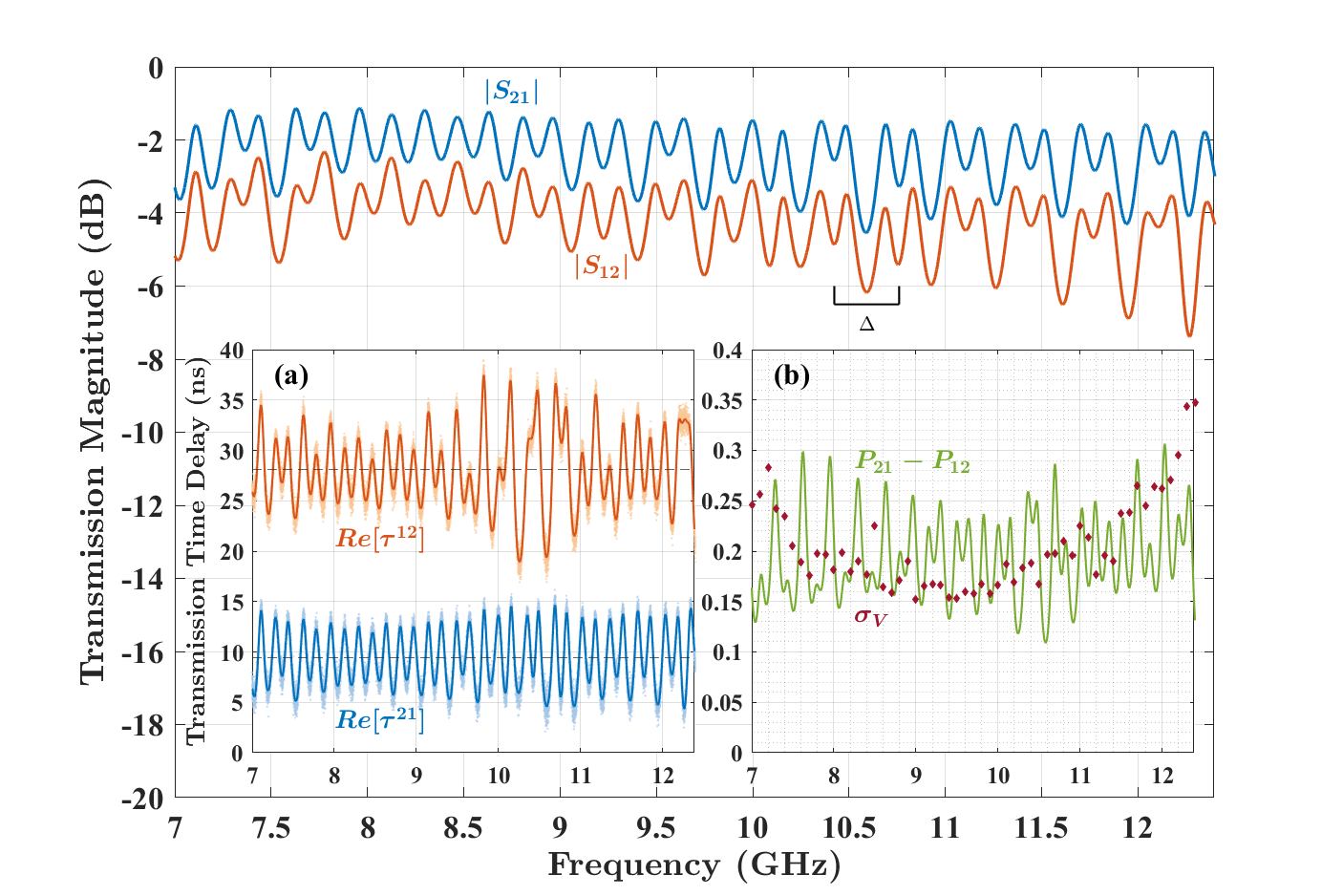
Transmission time delays The complex transmission time delays (see Methods) for both directions ( and ) can be calculated from the complex scattering matrix data as [48, 50, 49, 57, 52]. The results for the real part of transmission time delay in both directions, , , are shown in Fig. 4(a). The mean values are clearly different, while the regular variations of the transmission time delay plot come from the shape resonances of the ring graph, although here we are more interested in the ratio between the two transmission time delays. The mean values are 1.49 ns and 4.47 ns, with a ratio of 2.99. This demonstrates the average 3:1 ratio for the two transmission time delays in the Aharonov–Bohm ring microwave graph, based on frequency-domain data.
Asymmetric transmission One important result from Ref. [24] is the prediction of asymmetric transmission through the Aharonov–Bohm ring structure due to partial electron de-phasing. In the microwave domain, we utilize loss/attenuation as an analogy to de-phasing [37], as discussed above. We now extend this analogy to transport through a mesoscopic AB device. Figure 4 shows a comparison between forward and reverse transmission amplitudes and in the microwave AB-ring, where it can be seen that for all frequencies in the bandwidth of the device. The asymmetric transmission probability is plotted as a function of frequency in Fig. 4(b) (green line), demonstrating the broadband nature of the effect.
Time domain experiments The results presented so far have been obtained from microwave scattering matrix measurements performed entirely in the frequency domain. Electrons in mesoscopic systems are modeled as quantum wavepackets in the time domain. After demonstrating a 3:1 ratio between the two transmission time delays from the frequency-domain data, the question arises whether or not we can demonstrate the asymmetric delay directly in the time domain. Electron wave-packets do not have a single energy, as implied by our time-delay results obtain from S-matrix data, presented above. Therefore it is imperative that we examine the transport properties of our microwave graph with microwave pulses that are analogous to electron wavepackets in mesoscopic transport (see Methods). Figure 5 shows representative time-domain results of transmitted pulses emerging at each port when sending in the pulse from the other port. Here, an AWG generates the gaussian-modulated pulse of fixed carrier frequency used in the time-domain measurements. The pulse is a 1-ns wide Gaussian amplitude modulation of an -GHz carrier signal. Such a pulse includes approximately GHz bandwidth, which is well within the operating bandwidth of our gyrator-based AB microwave graph. The pulse will have the effect of averaging the non-reciprocal properties of the graph over a finite bandwidth. Here DUT is the device under test (the AB microwave ring graph), and the oscilloscope records the incident and transmitted signals. We measured the pulse transmission in both directions, and plot them on the same time axis. Shown for reference (yellow pulse in Figure 5) is the case where the DUT is absent, and this sets the zero of time for the pulse transmission measurements, as well as illustrating the relatively modest effects of pulse dispersion in the experiment. Figure 5 demonstrates directly a 3:1 ratio of the transmission time delays for pulses propagating through the AB graph in opposite directions. From the plot, the transmitted pulse from port 2 to port 1, , has smaller amplitude compared to the transmitted pulse from port 1 to port 2, .
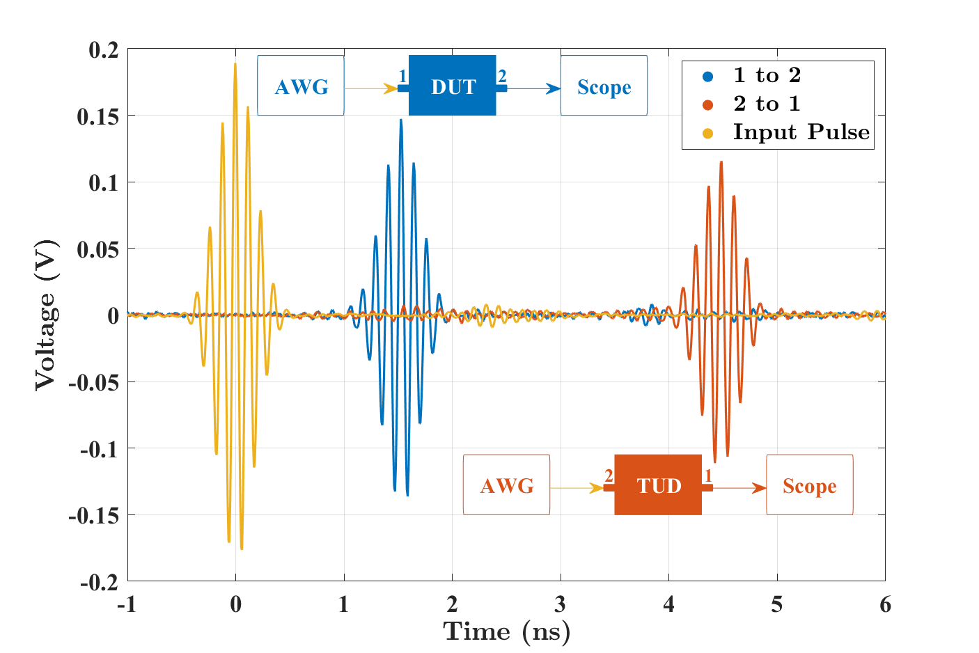
Figure 4(b) shows vs. pulse center frequency from the time-domain results in Fig. 13. The results are in good agreement with the transmission probability asymmetry from frequency domain measurements of the same graph. Figure 3(b) shows a plot of at a pulse center frequency of 8.5 GHz vs. the lumped attenuation in both bonds , as they are varied together. Adjusting both attenuators to the same attenuation setting preserves identical electrical path lengths on the two bonds of the microwave graph. We see once again the non-monotonic dependence of transmission asymmetry on variable lumped attenuation, and good agreement between frequency domain and time domain measurements.
Discussion The microwave AB-ring graph elegantly captures the fundamental wave interference, non-reciprocal and dissipative properties that give rise to asymmetric transmission. However, there are a number of limitations of the analogy between electromagnetic (EM) and mesoscopic quantum systems. In the EM analogue there are no quantum effects such as entanglement and collapse of the wavefunction, no Fermi-Dirac statistics, a linear (as opposed to quadratic) dispersion relation, and no electron-electron interactions. In the EM case the microwave photons are dissipated, whereas in the mesoscopic case the particle number is conserved, although the loss of coherence is well modeled by absorption in the EM case. Finally, the wave packet time evolution is different in detail, owing to the first-order nature of the time dependent Schrodinger equation, vs. the second order nature of the EM wave equation. Despite these differences, the EM analogy serves to clearly and unambiguously illustrate the basic principles of asymmetric transmission in corresponding mesoscopic systems.
It is an open question whether this approach to creating asymmetric transmission can be implemented in a mesoscopic metal or molecule. Numerous proposals have been put forward [19, 24, 6, 21, 9] that broken time-reversal invariance at the microscopic level can allow one to bypass constraints imposed by the Onsager relations, or restrictions against spontaneous currents [58, 19]. The authors of Refs. [21, 9] find it advantageous to employ a finite amount of decoherence, implemented through inelastic scattering, to create asymmetric transmission in a model mesoscopic device, suggesting that working in the regime between purely quantum and purely classical physics may be optimal for establishing a net transmission bias that spontaneously pumps charge from one equivalent reservoir to another. The AB ring graph effectively treats excitations moving in one direction more as waves, while the excitations travelling in the other direction are treated more as particles [59, 9].
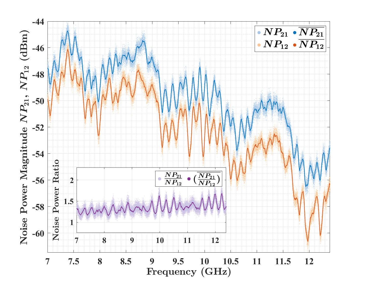
This brings up the question of what is the electromagnetic analogue to moving charge from one reservoir to another in the mesoscopic electron case? As a step in this direction, we propose the use of a broadband incoherent source of radiation and ask whether or not the asymmetric transmission properties are also exhibited when the AB-ring graph is excited in this way? Figure 6 shows the results of just such an experiment, in which a microwave noise source (see Methods) is used to illuminate the graph with incoherent noise. The experiment demonstrates broadband asymmetric transmission over the bandwidth of the device. The bandwidth-averaged asymmetric transmission probability was measured as a function of total attenuation in the AB-ring graph, and the results are shown in Fig. 3(c). This result shows that the non-monotonic dependence of transmission asymmetry exists even for a completely incoherent source of microwaves.
The results presented here for asymmetric transmission are obtained for the equilibrium properties of an analogous device. By contrast, a p-n junction diode also shows non-reciprocal transport, but only in the non-equilibrium situation of a finite voltage bias across the junction. The p-n junction is in fact reciprocal in the linear limit [9]. This implies that the proposed mesoscopic AB-ring device should be able to sort electrons from one equivalent reservoir to another, without being driven out of equilibrium, and in a direction dictated by the external magnetic field.
Other possible experimental settings in the intermediate range between coherent quantum and purely classical behavior (in addition to Ref. [26]) include the following. A mesoscopic AB-ring made of a clean metal, or ring-like molecule, with engineered de-phasing centers are candidates for showing asymmetric transmission in equilibrium [60, 9]. Another possibility is an AB-ring defined by interfaces supporting topological edge modes, as proposed for layers of buckled silicene [61]. Including a defect that creates inter-valley scattering of the electron wavepackets could generate bi-directional asymmetry of transport through the ring. Finally, it has been proposed that a class of monitored quantum devices can show a non-reciprocal current between reservoirs even in the absence of an applied bias [62].
In this paper, we present a microwave network structure that mimics the mesoscopic electron transport in a specially-engineered Aharonov–Bohm ring, and demonstrate a 3:1 ratio of the transmission time delays from different directions. The 3:1 ratio of the time delay has been illustrated in both frequency-domain and time-domain experiments. Using both simulations and experiments, we also demonstrate the asymmetric transmission through the microwave Aharonov–Bohm ring in both the frequency domain and time domain. The degree of asymmetric transmission is shown to be a non-monotonic function of attenuation/de-phasing in the ring, in agreement with expectations from mesoscopic theory for a system subjected to electron de-phasing. The experimental results on asymmetric transmission exist for both coherent and incoherent signal sources.
METHODS
CST Simulations Figure 7 shows the simulation schematic of the Aharonov–Bohm ring graph as a CST circuit model. Each port leads to a 3-way tee junction that acts as a beam-splitter and combiner for the incident waves from either direction, but having finite reflection for waves arriving on all three transmission lines. The upper branch is a finite length of uniform coaxial cable transmission line, while the lower branch contains a model gyrator. The upper and lower branches are chosen to have the same electrical length to eliminate Feshbach resonances [56, 52] and both branches contain a lumped-loss variable attenuator. The model closely approximates the experimental realization of the AB microwave graph. The model allows introduction of lumped loss (variable attenuator) and uniform loss (in all the coaxial cables) to the graph.
The shape modes of the ring graph involve standing wave patterns around the circumference of the ring and having a large overlap with propagating modes on the two leads [63, 56, 52]. The resulting poles and zeros of the scattering matrix are located relatively far from the real frequency axis [56, 52]. The Feshbach modes are an orthogonal set of modes that have minimal overlap with the extended modes on the leads, and create poles and zeros near the real frequency axis,[56, 52] giving rise to narrow spectral features.
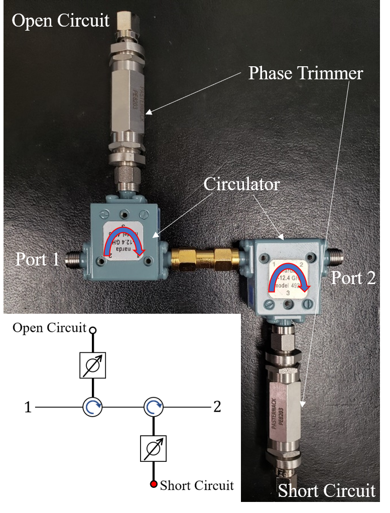
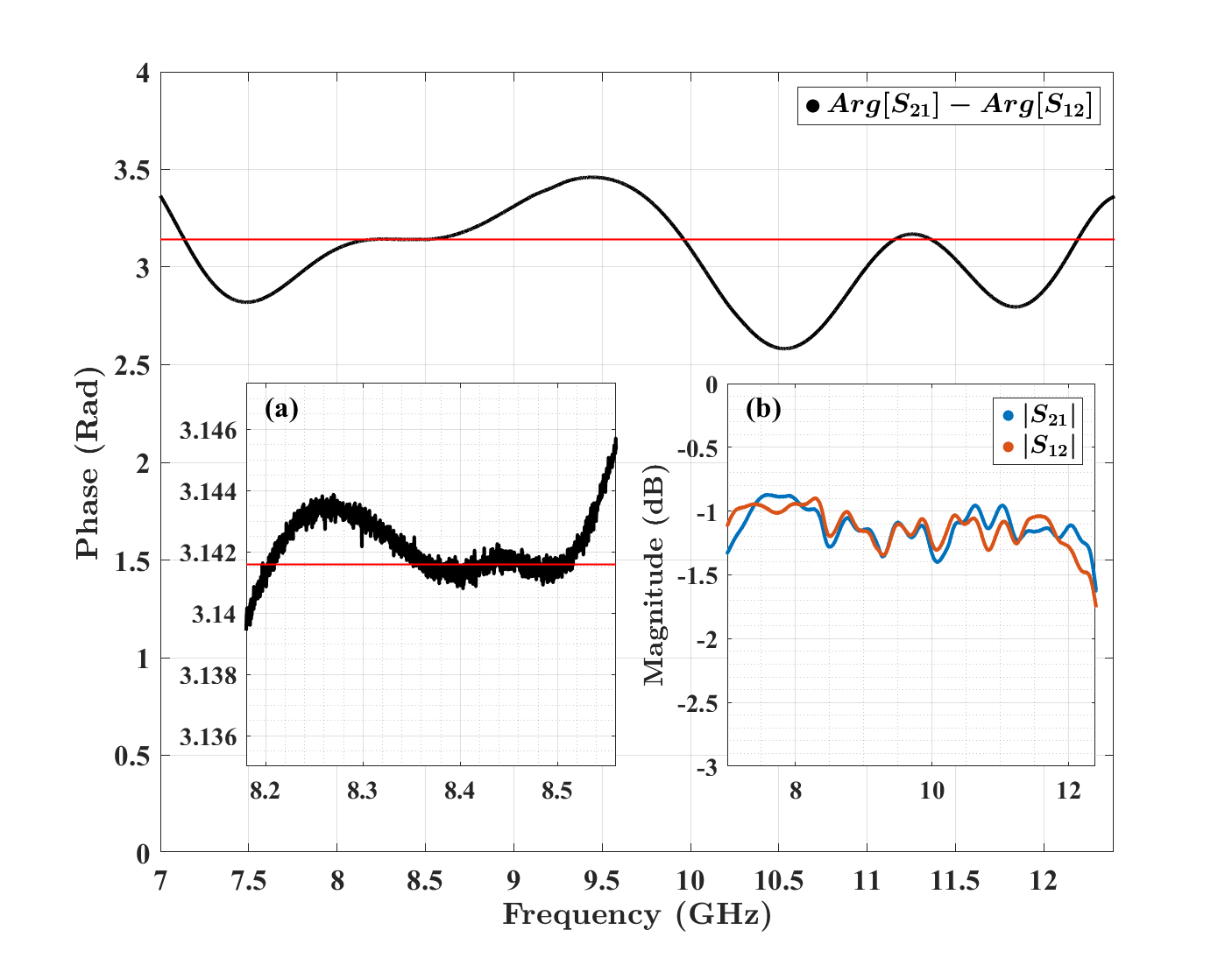
Aharonov-Bohm Microwave Graph Figure 9 shows the schematic design and photograph of the microwave gyrator setup. A wave travelling from port 1 to port 2 will be directed upwards and reflect from the open circuit on the left circulator, while the wave travelling in the opposite direction from port 2 will be directed downwards and reflect from the short circuit on the right circulator. The open/short circuits are designed to provide a phase difference for waves travelling in opposite directions, but due to the unequal finite electrical length of the components inside the circuits, the phase difference is not exactly . Thus, we add a pair of carefully adjusted phase trimmers in the design to compensate for the difference in electrical lengths. (This basic idea of creating 0 and phase shifts for left and right-going waves was inspired by the Gaussian Symplectic Ensemble graph presented in [64]) The measured phase difference between and between ports 1 and 2 in Fig. 9 as a function of frequency is shown in Fig. 10. The circulators used in the experiment have a working frequency range of GHz, and we measure the -matrix of the gyrator in that frequency range. This broad frequency range enables the time-domain measurements with wave packets. After doing some fine-tuning of the two phase trimmers, we are able to get the phase difference from the gyrator to be close to across the frequency band. We also verify that the insertion loss of the gyrator is symmetric (Fig. 10(b)). There are some small wiggles in these plots, which are due to the imperfection of the circulators and resulting standing waves inside the circuit. Note that the circulators contain microwave ferrites that are biased by a dc magnetic field in a fixed direction, dictating the circulation direction. The operating bandwidth of the circulators is what limits the overall bandwidth of the entire AB-ring graph.
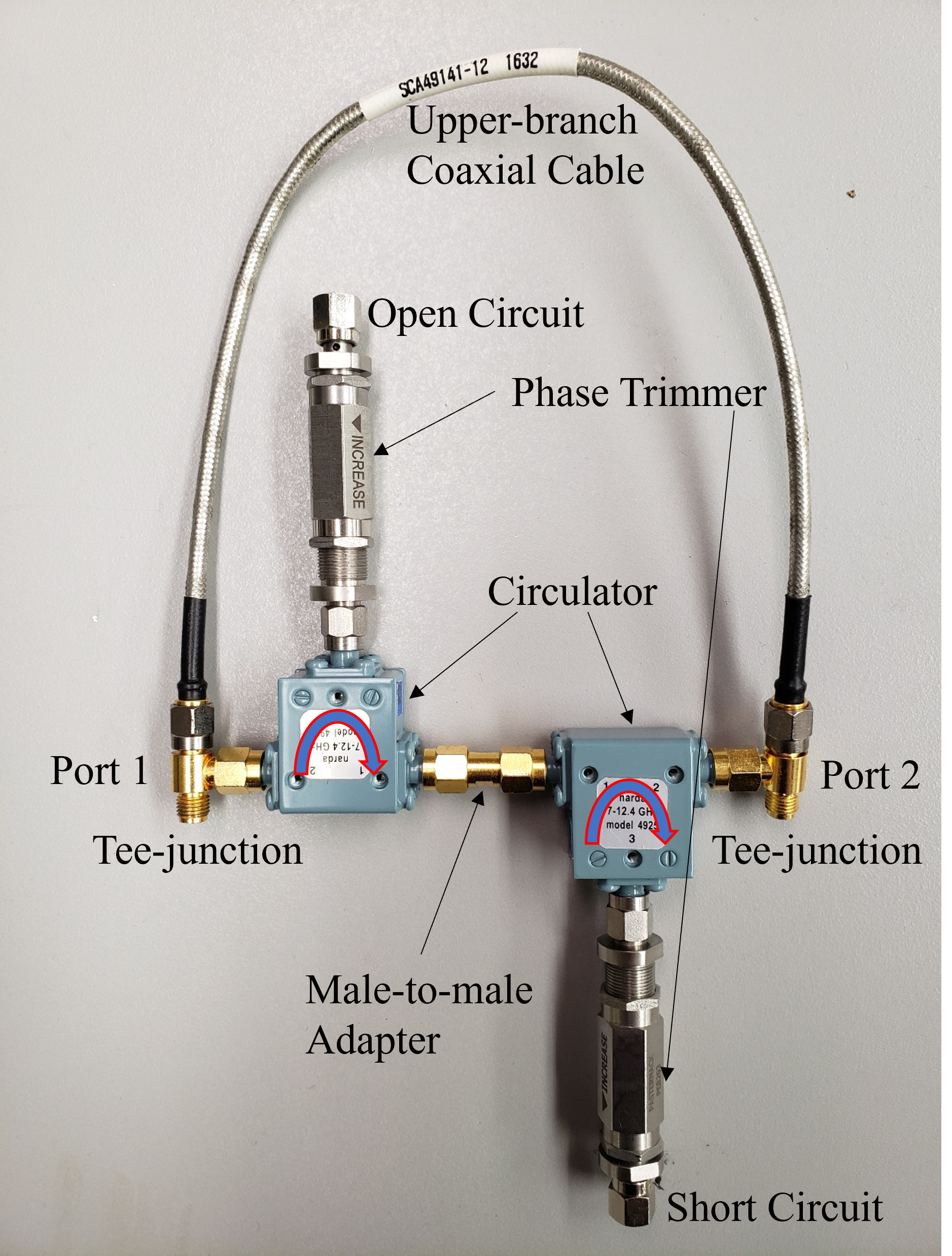
Next, we construct the Aharonov–Bohm ring microwave graph (see Fig. 11) using the gyrator design. The key is to add an upper branch to the ring that has the same electrical length as the gyrator, so that waves travelling from left to right in both branches would go through the same electrical length. Equating the electrical lengths of the branches also has the effect of eliminating the Feshbach modes, leaving only the shape resonances of the ring graph (see Refs. [52] and [56]). We measured the electrical length of the gyrator and a series of single coaxial cables, and selected a 12-inch-long coaxial cable as the upper branch. We then perform some fine-tuning on both phase trimmers to achieve an electrical length on the lower bond as close as possible to that of the 12-inch cable. The 12-inch coaxial cable has an electrical length of , and we manage to adjust the electrical length of the gyrator to be while maintaining a near phase difference for left/right transmission. The resulting microwave analogue of the AB graph with flux-induced phase shift is shown in Fig. 11.
Frequency Domain Measurements We measure the scattering () matrix of the 2-port AB-ring graph as a function of frequency. A Keysight N5242B network analyzer (PNA-X) is calibrated with a Keysight N4691D Electronic Calibration kit over the 7 - 12.4 GHz frequency range with a frequency step size of 168750 Hz. An Agilent Technologies N5242A vector network analyzer (VNA) is also used over the same frequency range; it is calibrated with an Agilent N4691-60001 Electronic Calibration kit with the same frequency step size. The device under test (DUT) is attached at the calibration planes of the network analyzer and the -matrix is measured as a function of frequency for various settings of the lumped attenuators in the microwave AB-ring graph.
A Microwave Semiconductor Corp (MSC) MC65242, 1.0 to 18 GHz noise source producing output ENR of 31.5 dB, is used to create broadband noise in the microwave domain. The noise signal is amplified by two Mini-Circuits amplifiers (ZX60-183A-S+) each with a bandwidth of 6 to 18 GHz. The two amplifiers are separated by one narda-MITEQ (94S46) attenuator with a bandwidth of 4 to 18 GHz. The amplified noise source is connected to one port of the AB-ring graph while the other port of the graph is connected to a network analyzer (Keysight N5242B). The network analyzer is used in receiving mode, with a resolution bandwidth of 10 kHz and 200 point averaging, to measure the transmitted power in a frequency resolved manner. The experiment is repeated with the ports on the AB-ring graph reversed.
Time Domain Measurements We perform pulse propagation measurements through the AB-ring graph in both directions, systematically varying the center frequency of the pulse, and measuring the time delays and amplitudes of the transmitted pulses. A Tektronix model AWG70001B Arbitrary Waveform Generator (AWG) is attached to the input port of the DUT, and the other port is attached to a Keysight/Infiniium model UXR0104A real-time oscilloscope. The input pulse created by the AWG is designed to be a 1-ns long Gaussian modulated pulse of center frequency , with ranging in value from 7 to 12.4 GHz. The pulse is measured by connecting the output of the AWG directly to the oscilloscope to establish the amplitude and timing of the incident pulse. The measurement is then repeated with the microwave AB-ring graph present in both orientations.
We note that prior measurements of pulse transport in microwave graphs has focused on the delay distribution and identifying orbits due to short closed loops in the graph [65].
Complex Time Delay We have introduced a generalized version of time delay applicable to sub-unitary scattering systems, such as the ring graph with either uniform or lumped attenuation, or both. The Wigner-Smith time delay for an -port scattering system described by the scattering matrix measured as a function of frequency is defined as [49] . This definition is a straightforward generalization of the Wigner-Smith time delay, previously considered only in the context of unitary quantum systems, to include variations in the magnitude of the scattering matrix with frequency. The complex Wigner-Smith time delay as a function of frequency can be expressed in terms of the pole and zero locations of the scattering matrix [49, 66] (see Supp. Mat.). We also utilize the complex reflection and transmission time delays to identify the zeros of the reflection and transmission sub-matrices, respectively. In this paper we evaluate the asymmetric complex transmission time delays of the port AB ring graph as [52] and . We have previously utilized all of the complex time delays to characterize the shape and Feshbach modes of the ordinary (as opposed to AB-) ring graph in terms of the zeros and poles of the scattering matrix and its transmission and reflection sub-matrices [52].
EXTENDED DATA
Here we provide essential background information relevant to the article. Figure 7 shows the schematic of the CST model of the microwave AB-ring graph used for the simulations presented in the article. All the transmission line blocks represent a coaxial cable with inner diameter of 0.091 cm, outer diameter of 0.298 cm, and relative dielectric constant of 2.01. The coaxial cables have two sources of loss, i.e. the dielectric loss tangent of the medium , and the resistivity of the metals in the cable m. These values reflect the parameters of the coaxial cables used in the experiment [52]. The attenuator blocks act as lumped loss elements which have adjustable attenuation.
For the simulation, we used a total graph length of m, which corresponds to a repetition frequency of GHz. The reason for this choice is that each branch has a total length of m, so the transmission time through either branch is ns. We can then most clearly display, as in Figure 8, the 3:1 ratio of transmission times as in one direction it will be ns and in the other it will be ns due to the gyrator.
Both frequency domain and time domain simulations were done with this model. In the frequency domain, we investigated the range of GHz, but only show a small section of the full range in Figs. 2 and 18 since the behavior of and is largely repetitive in frequency. In the case of finite uniform attenuation , both and decrease overall with frequency as the total loss increases, and decreases faster as the waves travelling from port 2 to port 1 spend more time in the graph and therefore experience more loss.
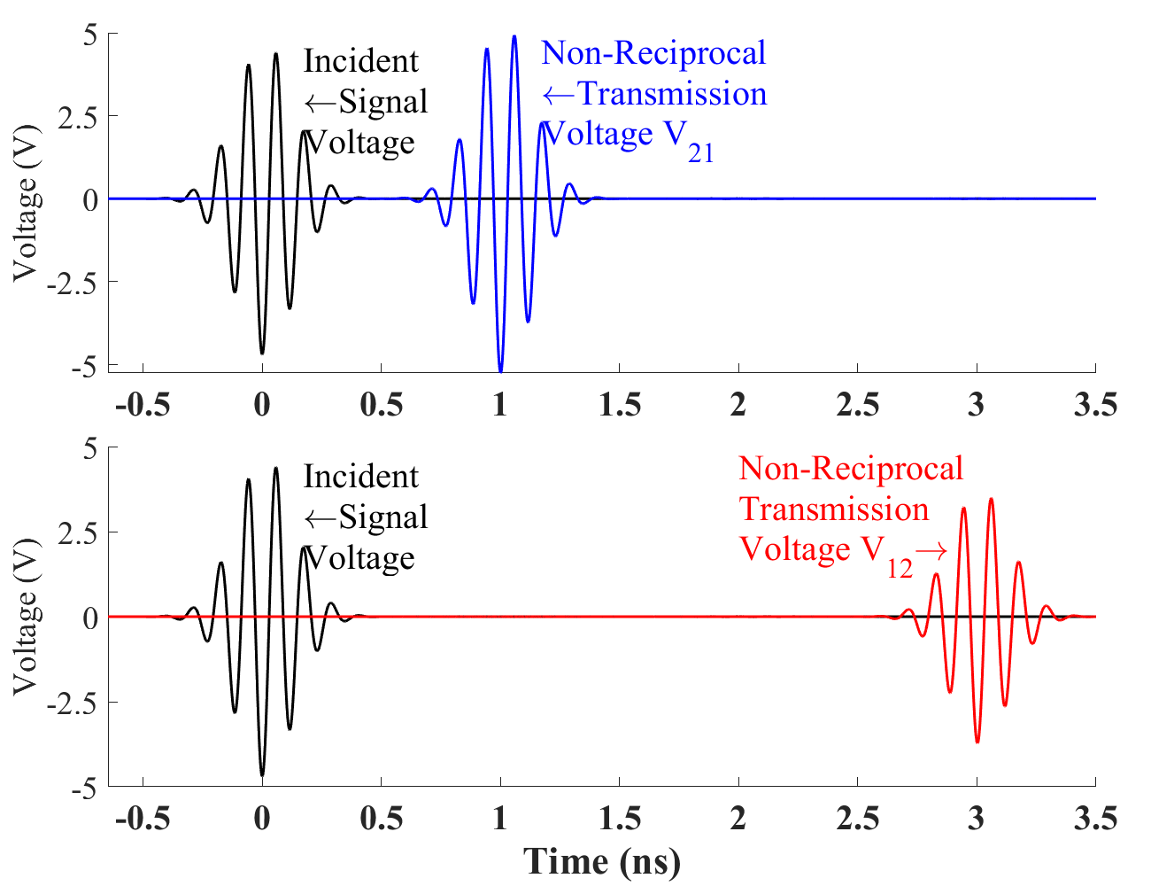
For the time domain simulations, signals of varying duration and center frequency were put in the model as incident pulses. Figure 8 shows the propagation of a ns pulse with center frequency GHz through the AB-ring graph in both directions. The incident pulse, portrayed in black, occurs at a normalized time of ns, and the transmission signal from port 1 to port 2 in blue occurs ns later, having the same temporal length and smaller amplitude. The transmission signal from port 2 to port 1, however, occurs at ns and has an even smaller amplitude. There is both uniform attenuation and a total of Np lumped attenuation in the graph in this case.
The gyrator schematic and laboratory realization are shown in Fig. 9. The measured transmission phase difference for right/left propagation through the experimentally realized gyrator is shown in Fig. 10. Inset (a) of that figure shows a closeup of the phase difference between 8.2 and 8.5 GHz, where the device shows nearly ideal behavior. Inset (b) shows the insertion loss for waves propagating in both directions, showing that they are nearly identical over the operating range of the gyrator.
Figure 11 shows a photograph of the assembled AB-ring microwave graph in the case where no lumped attenuators are present.
SUPPLEMENTARY MATERIAL
Loss of Detailed Balance in Equilibrium due to Partial Quantum Decoherence:
A Quantum Graph analogue
Lei Chen, Isabella L. Giovannelli, Nadav Shaibe, and Steven M. Anlage
We provide some additional details for some of the experiments and simulations described in the text of the Letter. In addition we present simulation and experimental results on a version of the AB-ring graph with a single lumped attenuator in the lower bond of the ring.
Detailed microwave AB-ring graph results. Figure 12 shows a photograph of the assembled microwave AB-ring graph with two attenuators present.
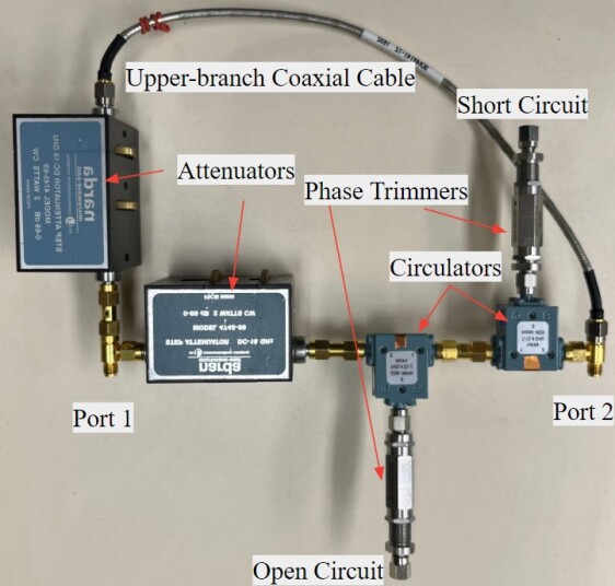
Figure 13 shows a plot of the two measured transmission times and pulse amplitudes, as a function of center frequency of the 1-ns wide gaussian pulse, over the bandwidth of the AB-ring microwave device with uniform attenuation only (i.e. no lumped attenuation). These are the results discussed in the section “Time domain experiments” and Fig. 5 of the main text. The left axis (green) demonstrates a consistent 3:1 ratio of the transmission time delays for pulses with different center frequencies propagating through the microwave AB graph in opposite directions. The right axis (blue) shows that the transmitted pulse from port 2 to port 1 always has smaller amplitude compared to the transmitted pulse from port 1 to port 2. As the pulse center frequency increases, both amplitudes decrease because the uniform attenuation of the microwave graph increases at higher frequency [52], but the asymmetric amplitudes are maintained. (A similar dependence of transmission amplitude vs. frequency is seen in the noise power transmission data in Fig. 6.) The resulting pulse transmission asymmetry vs. center frequency for this time-domain data is shown in Fig. 4(b).
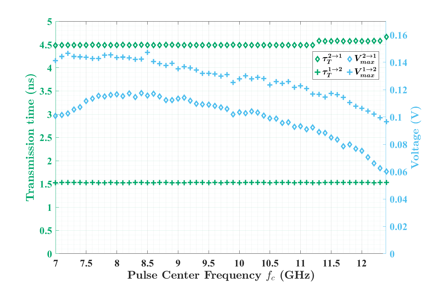
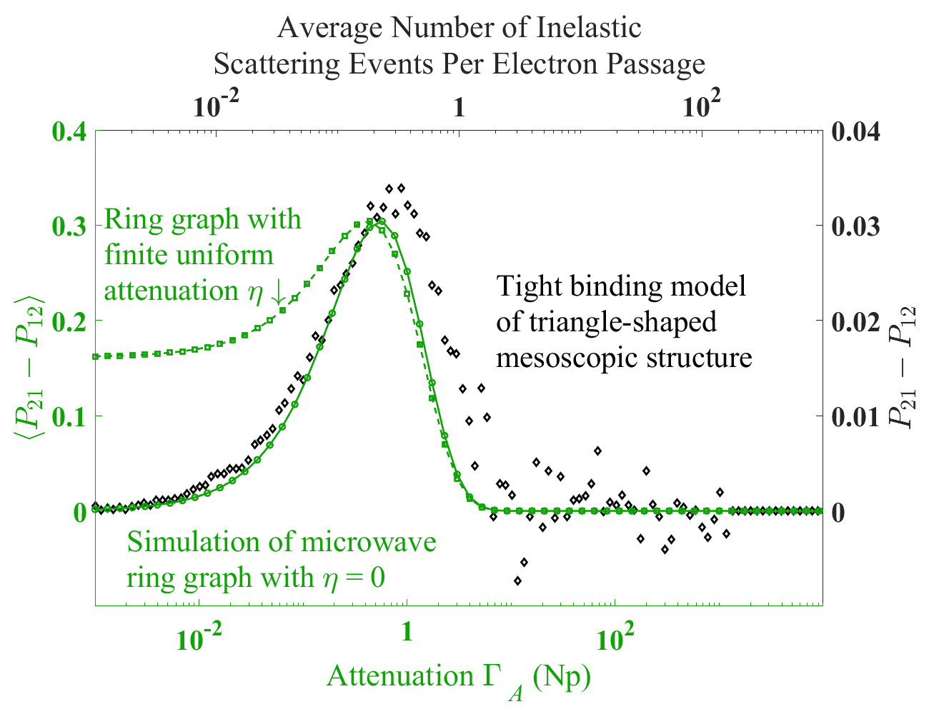
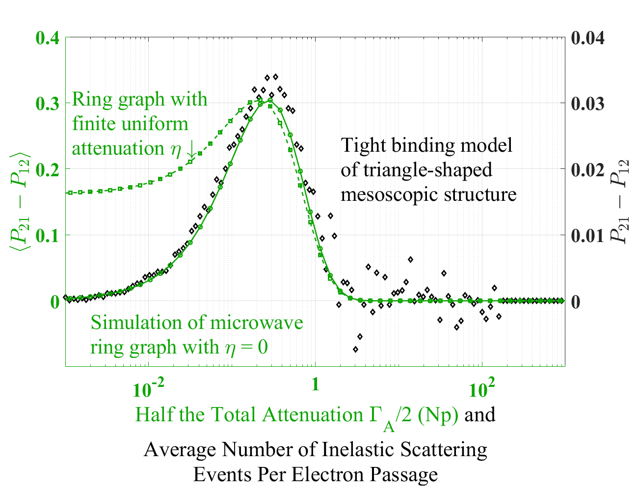
Figure 14 shows a plot of the asymmetric transmission for both the simulation of the Aharonov–Bohm microwave ring graph and the tight-binding model of an asymmetric triangle-shaped mesoscopic electron device containing an extended de-phasing center, from Refs. [9, 21]. Here the asymmetric transmission is presented as functions of total lumped attenuation in the microwave graph (in green) and average number of inelastic scattering events per electron passage through the modeled mesoscopic device (in black), respectively. Note that both independent degrees of freedom are plotted on a logarithmic scale, as opposed to the linear scale used in the main text, and that the axis has been shifted to the left so as to align the two peaks. The green circles and solid line are from a simulation with no uniform attenuation () while the squares and dashed line have a finite, frequency dependent uniform attenuation . Remarkably, the plot of the frequency averaged asymmetric transmission agrees in detail over many decades of attenuation/dephasing with the results of the mesoscopic, tight binding model calculations, although the vertical axes differ by a factor of 10. The agreement for the degree of asymmetric transmission vs. attenuation/dephasing again demonstrates the close connection between the two effects on wave transport [37]. The relationship becomes very clear in Figure 15 in which the same data is plotted but on a single shared logarithmic x-axis representing both one-half of the total lumped attenuation, on the two bonds, and the average number of inelastic scattering events per electron passage through the device. Now there is near alignment between the simulation results for the microwave ring graph with no uniform attenuation and the tight binding model of the mesoscopic device over the entire range of interest.
Poles and Zeros of the -Matrix of the AB-Ring graph. The AB-ring graph resonance properties in the frequency domain can be understood from the locations of the poles and zeros of the scattering matrix in the complex frequency plane. It is known that uniform attenuation preserves the complex conjugate relationship of the -matrix zeros and poles for each mode, but adds an overall offset in the definition of the -matrix [49, 52]. The lumped loss will act on the poles and zeros differently, allowing the real and imaginary parts of the poles and zeros to vary independently [49].
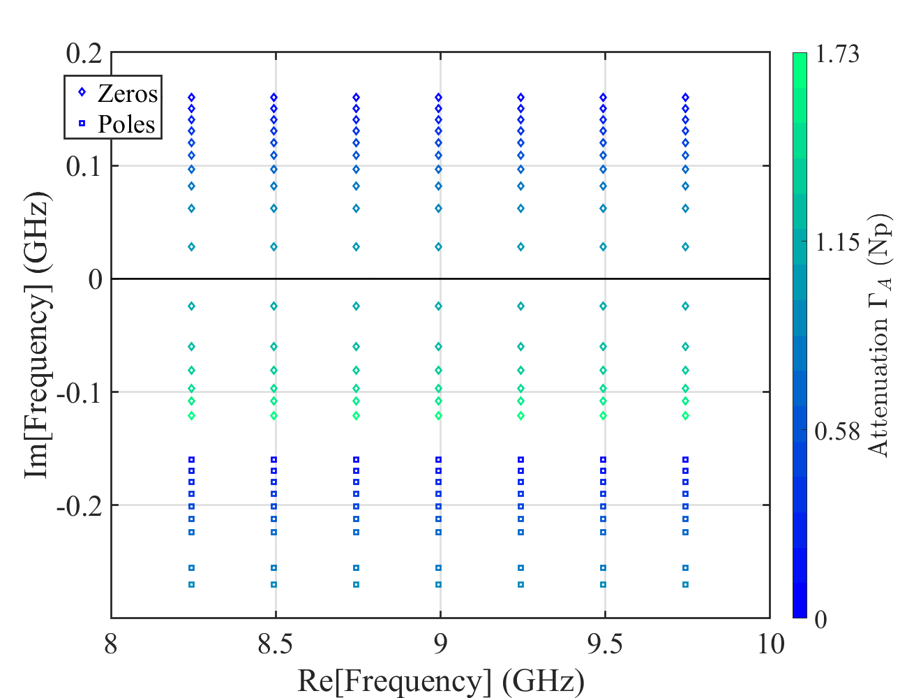
Figure 16 shows the motion of the zeros and poles (represented by diamonds and squares, respectively) as the lumped loss is increased from to Nepers in the simulation of the AB-ring graph with . The zero and pole locations are obtained by fitting the Wigner-Smith time delay as a function of frequency. The complex Wigner-Smith time delay is defined as , where is the number of ports, and is calculated from the measured (or simulated) scattering matrix in the frequency domain. These frequency dependent functions are simultaneously fit to these expressions [49, 52]:
| (1) |
| (2) |
where the complex frequency locations of the poles (, with the convention that in passive lossy systems) and zeros () of each mode are used as fitting parameters. As before, is the uniform attenuation. For the simulations used in Fig. 16 the increments in lumped attenuation are uniform, but the changes in the imaginary components of the zeros and poles are not, with the changes becoming more pronounced as the zeros approach the real axis. Interestingly, the zeros cross the real axis at around Np, but the peak in asymmetric transmission occurs at a little over Np. Note that the fits to complex are dominated by the zero locations when they are in the vicinity of the real frequency axis, hence the pole locations are not determined for Np.
Single-attenuator microwave AB-ring graph. A version of the AB-ring graph was also constructed with a single lumped attenuator on the lower bond, the schematic of which is shown in Figure 17. This version of the graph is a literal reproduction of the schematic form shown in Fig. 1(a). A photograph of the experimentally realized graph is shown in Fig. 20(b). The un-balanced nature of the attenuation in the two bonds leads to more complicated behavior of the scattering properties as the attenuation value is increased.

Figure 18(a) shows the simulated real part of the complex transmission time delay through the un-balanced version of the AB-ring graph as a function of frequency. The 3:1 asymmetry in transmission time delays is clearly seen, along with variations associated with the strong shape resonances. Figure 18(b) shows the simulated forward and reverse transmission amplitudes as a function of frequency for the case of lumped attenuation Np, with zero uniform attenuation. The case of no loss is not included here as it is identical to having two attenuators set to Np, shown in Figure 2, resulting in the graph having a unitary scattering matrix and symmetric transmission. In the Np lumped attenuation case the transmission is asymmetric for all frequencies except discrete values that repeat at intervals of the periodicity GHz. Figure 18(c) shows the difference in simulated transmission probabilities through the graph as a function of frequency in the unbalanced Np case, while the Np case has at all frequencies.
Figure 19 is the time domain analogue of Figure 18(a). Similar to Figure 8, there is both uniform attenuation and Np lumped attenuation in the simulation, but now all the lumped attenuation is located on one branch. The unbalanced attenuation creates a favored path for the waves to travel along, with a larger amplitude propagating through the branch without the lumped attenuation. When the waves travelling on the un-attenuated upper bond and attenuated lower bond later meet at a tee junction, they do not have the same amplitude. So despite the gyrator adding a phase shift to one side in one direction, the waves don’t perfectly interfere and reflect, and a small amount is transmitted. This is the cause of the small blue signal seen at ns and red signal at ns in Fig. 19. The reflected incident voltage at ns is due to the tee junctions having some intrinsic finite reflection, and now due to the unbalanced nature of the graph a small amount of the incident signal will return to escape through its input port, having made a complete return trip through the graph.
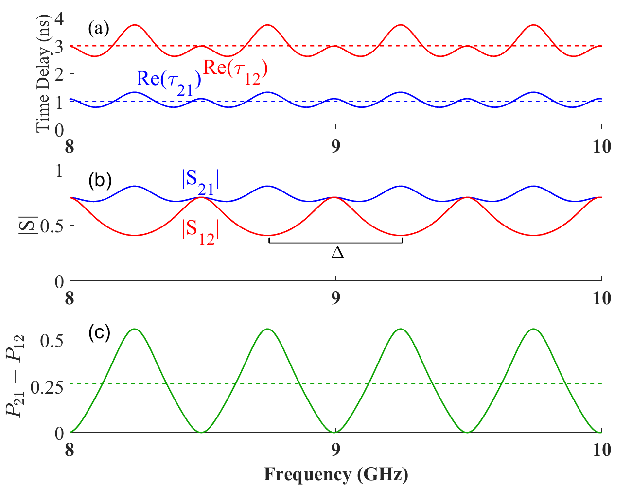
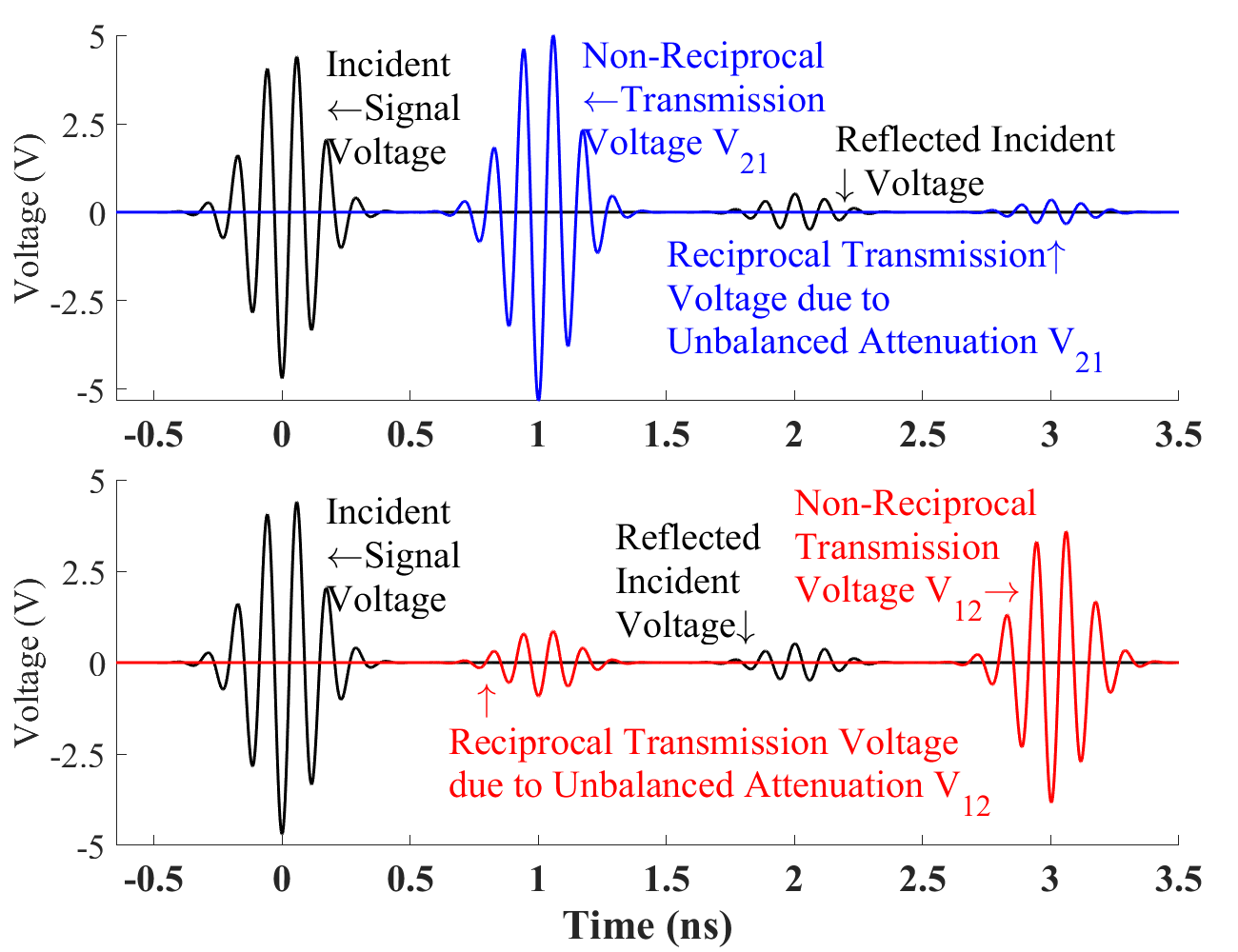
Figure 20 shows the experimental results for the asymmetric transmission through a microwave AB-ring graph having un-balanced attenuation in the bonds, as shown schematically in Fig. 17. The experiment includes finite uniform attenuation as well. Figure 20(a) shows a schematic of the AB-ring graph with one single attenuator. Figure 20(b) shows the experimental realization of Figure 20(a). Figure 20(c) repeats the asymmetric transmission results obtained from simulations of the quantum system shown in the inset, as presented in the main text. Figure 20(d) shows the frequency domain asymmetric transmission results for both experiment (green symbols) and simulation (green solid and dashed lines). Figure 20(e) shows the time domain results for both experiment (red symbols) and simulation (red solid and dashed lines).
The un-balanced AB-ring microwave graph retains all of the asymmetric properties of the fully balanced version, but these features are obscured to some extent by the design of the graph. Hence even a literal interpretation of the graph shown in Fig. 1(a) still shows the remarkable asymmetric transmission properties of the balanced version of the graph.

References
- Jarzynski [2011] C. Jarzynski, Equalities and inequalities: Irreversibility and the second law of thermodynamics at the nanoscale, Annual Review of Condensed Matter Physics 2, 329 (2011).
- Seifert [2012] U. Seifert, Stochastic thermodynamics, fluctuation theorems and molecular machines, Reports on Progress in Physics 75, 126001 (2012).
- Zurek [1991] W. H. Zurek, Decoherence and the transition from quantum to classical, Physics Today 44, 36 (1991).
- Joos [2003] E. Joos, Decoherence and the appearance of a classical world in quantum theory, second edition. ed. (Springer, Berlin ;, 2003).
- Fortin and Lombardi [2019] S. Fortin and O. Lombardi, The correspondence principle and the understanding of decoherence, Foundations of Physics 49, 1372 (2019).
- Braak and Mannhart [2020] D. Braak and J. Mannhart, Fermi’s golden rule and the second law of thermodynamics, Foundations of Physics 50, 1509 (2020).
- Wang et al. [2021] J. Wang, G. Benenti, G. Casati, and W.-g. Wang, Quantum chaos and the correspondence principle, Physical Review E 103, L030201 (2021).
- Astumian and Hänggi [2002] R. D. Astumian and P. Hänggi, Brownian motors, Physics Today 55, 33 (2002).
- Mannhart et al. [2021] J. Mannhart, H. Boschker, and P. Bredol, Non-unitary quantum electronics: Novel functions from the edge of the quantum world, Nano Express 2, 014008 (2021).
- Valenzuela et al. [2006] S. O. Valenzuela, W. D. Oliver, D. M. Berns, K. K. Berggren, L. S. Levitov, and T. P. Orlando, Microwave-induced cooling of a superconducting qubit, Science 314, 1589 (2006).
- Maxwell [1872] J. C. Maxwell, Theory of Heat (Longmans, Green, and Co., New York, 1872).
- Čápek and Sheehan [2005] V. Čápek and D. Sheehan, Challenges to The Second Law of Thermodynamics (Springer, Dordrecht, 2005).
- Reimann [2002] P. Reimann, Brownian motors: noisy transport far from equilibrium, Physics Reports 361, 57 (2002).
- Tokura and Nagaosa [2018] Y. Tokura and N. Nagaosa, Nonreciprocal responses from non-centrosymmetric quantum materials, Nature Communications 9, 3740 (2018).
- Zhu and Fan [2014] L. Zhu and S. Fan, Near-complete violation of detailed balance in thermal radiation, Physical Review B 90, 220301 (2014).
- Zhu and Fan [2016] L. Zhu and S. Fan, Persistent directional current at equilibrium in nonreciprocal many-body near field electromagnetic heat transfer, Physical Review Letters 117, 134303 (2016).
- Lepri and Casati [2011] S. Lepri and G. Casati, Asymmetric wave propagation in nonlinear systems, Physical Review Letters 106, 164101 (2011).
- Bender et al. [2013] N. Bender, S. Factor, J. D. Bodyfelt, H. Ramezani, D. N. Christodoulides, F. M. Ellis, and T. Kottos, Observation of asymmetric transport in structures with active nonlinearities, Physical Review Letters 110, 234101 (2013).
- Mannhart [2018] J. Mannhart, Non-reciprocal interferometers for matter waves, Journal of Superconductivity and Novel Magnetism 31, 1649 (2018).
- Bredol [2021] P. Bredol, Nonreciprocity of the wave-packet scattering delay in ballistic two-terminal devices, Physical Review B 103, 035404 (2021).
- Bredol et al. [2021] P. Bredol, H. Boschker, D. Braak, and J. Mannhart, Decoherence effects break reciprocity in matter transport, Physical Review B 104, 115413 (2021).
- Aharonov and Bohm [1959] Y. Aharonov and D. Bohm, Significance of electromagnetic potentials in the quantum theory, Phys. Rev. 115, 485 (1959).
- Mannhart and Braak [2019] J. Mannhart and D. Braak, Lossless currents at high temperatures, Journal of Superconductivity and Novel Magnetism 32, 17 (2019).
- Mannhart [2020] J. Mannhart, Beyond Superconductivity, Journal of Superconductivity and Novel Magnetism 33, 249 (2020).
- Entin-Wohlman et al. [1995] O. Entin-Wohlman, Y. Imry, A. G. Aronov, and Y. Levinson, Orbital magnetization in the hopping regime, Physical Review B 51, 11584 (1995).
- Gou et al. [2020] W. Gou, T. Chen, D. Xie, T. Xiao, T.-S. Deng, B. Gadway, W. Yi, and B. Yan, Tunable nonreciprocal quantum transport through a dissipative aharonov-bohm ring in ultracold atoms, Physical Review Letters 124, 070402 (2020).
- McDonald and Kaufman [1979] S. W. McDonald and A. N. Kaufman, Spectrum and eigenfunctions for a hamiltonian with stochastic trajectories, Physical Review Letters 42, 1189 (1979).
- Stockmann and Stein [1990] H. J. Stockmann and J. Stein, Quantum chaos in billiards studied by microwave-absorption, Physical Review Letters 64, 2215 (1990).
- Stöckmann [1999] H.-J. Stöckmann, Quantum Chaos: An Introduction (Cambridge University Press, 1999).
- Kim et al. [2002] Y.-H. Kim, M. Barth, H.-J. Stöckmann, and J. P. Bird, Wave function scarring in open quantum dots: A microwave-billiard analog study, Physical Review B 65, 165317 (2002).
- Kim et al. [2003] Y. H. Kim, M. Barth, U. Kuhl, H. J. Stöckmann, and J. P. Bird, Scanning fourier spectroscopy: A microwave analog study to image transmission paths in quantum dots, Physical Review B 68, 045315 (2003).
- Dragoman and Dragoman [2004] D. Dragoman and M. Dragoman, Quantum-classical analogies, The Frontiers collection, 1612-3018 (Springer, Berlin, 2004).
- Kim et al. [2005] Y. H. Kim, U. Kuhl, H. J. Stockmann, and J. P. Bird, Investigating dynamical tunnelling in open quantum dots by means of a soft-walled microwave-cavity analogue, Journal of Physics-Condensed Matter 17, L191 (2005).
- Pauling [1936] L. Pauling, The diamagnetic anisotropy of aromatic molecules, The Journal of Chemical Physics 4, 673 (1936).
- Hul et al. [2004] O. Hul, S. Bauch, P. Pakoński, N. Savytskyy, K. Życzkowski, and L. Sirko, Experimental simulation of quantum graphs by microwave networks, Physical Review E 69, 056205 (2004).
- Seba et al. [1999] P. Seba, U. Kuhl, M. Barth, and H. J. Stockmann, Experimental verification of topologically induced vortices inside a billiard, Journal of Physics a-Mathematical and General 32, 8225 (1999).
- Hemmady et al. [2006] S. Hemmady, J. Hart, X. Zheng, T. M. Antonsen, E. Ott, and S. M. Anlage, Experimental test of universal conductance fluctuations by means of wave-chaotic microwave cavities, Physical Review B 74, 195326 (2006).
- Brouwer and Beenakker [1997] P. W. Brouwer and C. W. J. Beenakker, Voltage-probe and imaginary-potential models for dephasing in a chaotic quantum dot, Physical Review B 55, 4695 (1997).
- Kottos and Smilansky [1997] T. Kottos and U. Smilansky, Quantum chaos on graphs, Physical Review Letters 79, 4794 (1997).
- Kottos and Smilansky [1999] T. Kottos and U. Smilansky, Periodic orbit theory and spectral statistics for quantum graphs, Annals of Physics 274, 76 (1999).
- Richardson and Balazs [1972] M. J. Richardson and N. L. Balazs, On the network model of molecules and solids, Annals of Physics 73, 308 (1972).
- Exner [1995] P. Exner, Lattice Kronig-Penney Models, Physical Review Letters 74, 3503 (1995).
- Sánchez-Gil et al. [1998] J. A. Sánchez-Gil, V. Freilikher, I. Yurkevich, and A. A. Maradudin, Coexistence of ballistic transport, diffusion, and localization in surface disordered waveguides, Physical Review Letters 80, 948 (1998).
- Chalker and Coddington [1988] J. T. Chalker and P. D. Coddington, Percolation, quantum tunnelling and the integer hall effect, Journal of Physics C: Solid State Physics 21, 2665 (1988).
- Kowal et al. [1990] D. Kowal, U. Sivan, O. Entin-Wohlman, and Y. Imry, Transmission through multiply-connected wire systems, Physical Review B 42, 9009 (1990).
- Hu et al. [2015] W. Hu, J. C. Pillay, K. Wu, M. Pasek, P. P. Shum, and Y. D. Chong, Measurement of a topological edge invariant in a microwave network, Physical Review X 5, 011012 (2015).
- Dietz et al. [2017] B. Dietz, V. Yunko, M. Białous, S. Bauch, M. Ławniczak, and L. Sirko, Nonuniversality in the spectral properties of time-reversal-invariant microwave networks and quantum graphs, Physical Review E 95, 052202 (2017).
- Asano et al. [2016] M. Asano, K. Y. Bliokh, Y. P. Bliokh, A. G. Kofman, R. Ikuta, T. Yamamoto, Y. S. Kivshar, L. Yang, N. Imoto, Ş. K. Özdemir, and F. Nori, Anomalous time delays and quantum weak measurements in optical micro-resonators, Nature Communications 7, 13488 (2016).
- Chen et al. [2021a] L. Chen, S. M. Anlage, and Y. V. Fyodorov, Generalization of Wigner time delay to subunitary scattering systems, Physical Review E 103, L050203 (2021a).
- del Hougne et al. [2021] P. del Hougne, K. B. Yeo, P. Besnier, and M. Davy, On-demand coherent perfect absorption in complex scattering systems: Time delay divergence and enhanced sensitivity to perturbations, Laser & Photonics Reviews 15, 2000471 (2021).
- Huang et al. [2022] Y. Huang, Y. Kang, and A. Z. Genack, Wave excitation and dynamics in non-hermitian disordered systems, Physical Review Research 4, 013102 (2022).
- Chen and Anlage [2022] L. Chen and S. M. Anlage, Use of transmission and reflection complex time delays to reveal scattering matrix poles and zeros: Example of the ring graph, Phys. Rev. E 105, 054210 (2022).
- Tellegen [1948] B. D. Tellegen, The gyrator, a new electric network element, Philips Res. Rep. 3, 81–101 (1948).
- Hogan [1953] C. L. Hogan, The ferromagnetic faraday effect at microwave frequencies and its applications, Reviews of Modern Physics 25, 253 (1953).
- Viola and DiVincenzo [2014] G. Viola and D. P. DiVincenzo, Hall effect gyrators and circulators, Physical Review X 4, 021019 (2014).
- Waltner and Smilansky [2013] D. Waltner and U. Smilansky, Scattering from a ring graph - a simple model for the study of resonances, Acta Physica Polonica A 124, 1087 (2013).
- Kang and Genack [2021] Y. Kang and A. Z. Genack, Transmission zeros with topological symmetry in complex systems, Physical Review B 103, L100201 (2021).
- Ohashi and Momoi [1996] Y. Ohashi and T. Momoi, On the bloch theorem concerning spontaneous electric current, Journal of the Physical Society of Japan 65, 3254 (1996).
- Mannhart et al. [2019] J. Mannhart, P. Bredol, and D. Braak, Phase filters for a novel kind of asymmetric transport – scientific prospects and opportunities for possible applications, Physica E: Low-dimensional Systems and Nanostructures 109, 198 (2019).
- Leturcq et al. [2006] R. Leturcq, D. Sánchez, G. Götz, T. Ihn, K. Ensslin, D. C. Driscoll, and A. C. Gossard, Magnetic field symmetry and phase rigidity of the nonlinear conductance in a ring, Physical Review Letters 96, 126801 (2006).
- Szafran et al. [2019] B. Szafran, B. Rzeszotarski, and A. Mreńca-Kolasińska, Topologically protected wave packets and quantum rings in silicene, Physical Review B 100, 085306 (2019).
- Ferreira et al. [2023] J. Ferreira, T. Jin, J. Mannhart, T. Giamarchi, and M. Filippone, Exact description of transport and non-reciprocity in monitored quantum devices (2023), arXiv:2306.16452 [quant-ph] .
- Exner and Lipovský [2010] P. Exner and J. Lipovský, Resonances from perturbations of quantum graphs with rationally related edges, Journal of Physics A: Mathematical and Theoretical 43, 105301 (2010).
- Rehemanjiang et al. [2016] A. Rehemanjiang, M. Allgaier, C. H. Joyner, S. Müller, M. Sieber, U. Kuhl, and H.-J. Stöckmann, Microwave realization of the gaussian symplectic ensemble, Physical Review Letters 117, 064101 (2016).
- Białous et al. [2021] M. Białous, P. Dulian, A. Sawicki, and L. Sirko, Delay-time distribution in the scattering of short gaussian pulses in microwave networks, Physical Review E 104, 024223 (2021).
- Chen et al. [2021b] L. Chen, S. M. Anlage, and Y. V. Fyodorov, Statistics of complex wigner time delays as a counter of -matrix poles: Theory and experiment, Physical Review Letters 127, 204101 (2021b).
Acknowledgements We acknowledge insightful discussions with Dr. Jochen Mannhart, and assistance from Jingnan Cai. This work was supported by ONR under grant N000142312507, NSF/ECCS/RINGS under grant 2148318, DARPA/WARDEN under grant HR00112120021, ONR/DURIP FY21 under grant N000142112924, and ONR/DURIP FY22 under grant N000142212263.
Author contributions S.M.A. conceived and directed the research, L.C. performed the initial simulations and measurements, I.L.G. and N.S. contributed substantial improvements to the experiment and carried out new simulations, experiments, and analysis.
Competing interests The authors have no competing interests to declare.
Correspondence and requests for materials should be addressed to Steven Anlage.