A Robot Leg with Compact Variable Stiffness Joint based on Leaf-Spring Mechanism
Abstract
The legged robots with variable stiffness actuators (VSAs) can achieve energy-efficient and versatile locomotion. However, equipping legged robots with VSAs in real-world application is usually restricted by (i) the redundant mechanical structure design, (ii) limited stiffness variation range and speed, and (iii) high energy consumption in stiffness modulation. In this paper, we present a novel Variable-Length Leaf-Spring Actuator (VLLSA) in legged robots that aims to address the aforementioned limitations. The design is based on leaf-spring mechanism and we improve the structural design to make the proposed VSA (i) compact and lightweight in mechanical structure, (ii) precise in theoretical modeling, and (iii) capable of modulating stiffness with wide range, fast speed, and low energy consumption. Hardware experiments validate that the legged robot equipped with the proposed VLLSA has compact structure, high dynamic performance and low energy consumption.
I Introduction
Dynamic tasks, such as hopping, are characterized by the rapid release of a large amount of energy over a short duration, making them a kind of explosive movements [1, 2]. Variable stiffness actuators (VSAs) can change the output stiffness instantly with specific mechanical design, it is demonstrated that introducing VSAs could improve human–robot interaction, enable versatile locomotion in dynamic tasks [3, 4, 5, 6].
Integrating VSAs with elastic parts can be achieved through two configurations: series elastic actuation (SEA) and parallel elastic actuation (PEA) [7]. SEA integrates the elastic part between the actuator and the load in series connection, and has been applied successfully in many mobile and bionic robotic systems, such as ScarlETH [8], ANYmal robot [9], and ATRIAS [10], where the SEAs are installed in the knee and hip joints. It is demonstrated that SEA can offer several advantages, including the enhanced error tolerance in joint positioning [11], reduced impact loads [12], and precise torque measurement [13]. However, SEA demands large motor size or gear ratio in the rotary joints [14]. This not only renders the robot’s overall design redundant but also diminishes the prospects of achieving agile locomotion.
Parallel elastic actuation (PEA) shares a similar structure with SEA but is structured by placing the actuator and elastic part in parallel [12]. Such configuration reduces the energy consumption of the actuators by replacing a portion of actuator generated torque with elastic parts like springs [15, 16]. When a robot is engaged in highly dynamic locomotion with a large motion range, PEA is proved as a more energy-efficient choice compared to SEA, as long as its no-load angle is appropriately adjusted [17, 18]. For instance, a PEA is integrated in the BioBiped3 robot by employing pneumatic air muscles as parallel elastic elements, leading to improved energy efficiency and robustness [19]; the knee joint of a legged robot equipped with the L-MESTRAN can adjust stiffness to enhance energy efficiency during hopping locomotion across various stride frequencies [20]. Recent research on PEA has focused on optimizing PEA design for different environments, employing model-free reinforcement learning and Bayesian optimization frameworks to identify the ideal design parameters, specifically for the elliptic component of the PEA [21, 22]. However, the effectiveness of PEAs is often constrained by the specifications of stiffness variation range and modulation power. The existing stiffness range fails to fulfill the demands of versatile maneuvers, and the energy consumed by stiffness modulation constitutes a significant portion of the overall energy consumption [23]. This is especially noteworthy when dealing with tasks of high dynamism, the time taken for stiffness switching serves as a crucial benchmark in such scenarios [24]. Besides, the inclusion of clutches and additional mechanical components increases the total mass of the whole structure, while the stiffness modulation still couples with the robot configuration, both factors deteriorates the control performance in dynamic tasks [25].
In this paper, we propose a novel Variable-Length Leaf-Spring Actuator (VLLSA) for highly dynamic legged-robotic system, as shown in Fig. 1. The proposed VLLSA belongs to the category of PEA, but overcomes the aforementioned limitations of existing VSA designs, enhancing the performance of legged robots in dynamic tasks. The elastic element we utilized in VLLSA is the leaf-spring which has been employed in prosthetic devices[24, 26] and wearable exoskeletons[23, 27], the compliant characters of leaf spring exhibit exceptional stiffness modulation and energy efficiency [28]. The VLLSA is designed with a direct connection to the knee joint, featured in introducing a slider with two pairs of roller bearings that could actively change the effective length of the elastic leaf-spring. This design enables convenient modification of the output stiffness, allowing for independent and versatile stiffness modulation to robot configuration. The endpoint of the leaf-spring is fixed to a linear guide, ensuring that the undeflected portion of the leaf-spring remains parallel to the movement of the slider. To improve the control performance of legged robot with VLLSA, the model of the VLLSA is built, analyzed and experimentally verified with real-world experiments.
The main contributions of this paper are:
-
1.
We present a novel design of VSA used in the legged robotic system. Compared to the state-of-the-art, the proposed design introduces leaf spring based VSA into the dynamic legged robotic systems, and the proposed VLLSA is designed to be compact and lightweight, enabling convenient installation and versatile robot locomotion.
-
2.
The theoretical model of the VLLSA is derived and analyzed for precise open-loop control. The specific design of the VLLSA, e.g., employing linear guide and gear set, ensures the precise modeling of the output stiffness with respect to the slider position and leaf-spring deflection angle. Such design feature facilitates accurate open-loop control of the output stiffness in VLLSA.
-
3.
We present comprehensive experimental validations of the proposed VLLSA in legged robotic system. The VLLSA is validated to provide output stiffness with wider range, faster speed, and lower energy consumption in hardware test; the legged robot with VLLSA is implemented in real-world hopping tasks to demonstrate its advantages in high dynamic performance and low energy consumption.
The paper is structured as follows: In Section II, we introduce the mechanical design and mathematical model of the VLLSA. IN Section III, we analyze the properties of VLLSA using the theoretical model and verify with real-world experiments. In Section IV, we describe the hopping control method for the legged robot. In Section V, we present the experimental setup and discuss the results. In Section VI, we conclude the paper.
II Variable Length leaf-spring Actuator
II-A Mechanical structure
We present the prototype of a legged robotic system equipped with VLLSA (VLLSA-leg) , as is shown in Fig. 1. The VLLSA-leg consists of a hip and a knee joint, both of which are actuated by the same type of motors placed at the same axis to reduce the rotational inertia of the legs. A rigid parallel four-bar structure is used to deliver the knee torque. The joint motors are direct torque-controlled, the joint angular feedback signals are obtained from the absolute encoders installed inside the motors, and are calibrated by reaching the limit position of each joints, similar to the MIT cheetah robot [29]. The main parts of the VLLSA-leg are 3D printed and the structure is reinforced with carbon fiber board to minimize the self-weight.
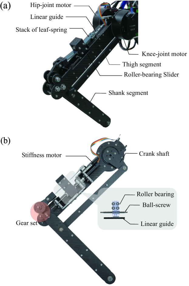
Considering the VLLSA shown in Fig. 1b, the drive system to change effective length of leaf-spring consists of the ball-screw, roller-bearing slider and a high-speed brushless DC motor. The ball-screw driven by the motor is used to control position of the roller-bearing slider, which is supported by a linear guide to change the effective length of the leaf-spring. Changing stiffness requires low power when the device is at initial equilibrium state. Even without any electric energy input, the ball screw is capable of holding stiffness under a certain applied torque; meanwhile, the ball screw ensures that the motion of the roller block is back-drivable and energy-efficient. Output of the VLLSA is directly connected to the knee joint via gear set and the elastic portion employs a stack of leaf springs with 65 Mn steel. Furthermore, the VLLSA is compactly designed and could be installed inside the thigh segment to make full use of the inner space. These features facilitate the VLLSA to provide variable stiffness modulation without bulky and heavy structure, and could change the output stiffness with high speed and low energy cost.
II-B Theory guided design
Gear set: We aim to derive the mathematical model of VLLSA using Bernoulli-Euler beam theory [30]. Large deflection in leaf spring usually leads to high nonlinearity, complicating the derivation of the output stiffness and consequently introducing modeling error; therefore, small deflection in leaf spring during robot operation is usually preferred. However, as the leaf spring is directly output to the knee joint, keeping small deflection in leaf spring would limit the operation range of knee joint and the dynamic performance of the legged robot. In our design, a custom made gear set is installed between the knee joint and the output of VLLSA, as marked in Fig. 1b, the gear ratio is . The gear set keeps the deformation of the active leaf spring within a small and safe range, while ensure the knee joint of the legged robot has enough range of motion, i.e., where is the initial angle when leaf spring is undeflected. The output torque of VLLSA and the gear-driven knee joint torque has the relation as .
Dual roller bearing & Linear slider: Another crucial factor that significantly affects the precision of stiffness estimation is the bending configuration of the leaf spring. For an ideal cantilever support, it is essential that the undeflected segment maintains a zero slope at the contact point; in the VLLSA we employ the dual roller-bearing slider as the cantilever support, allowing movement along the length of the leaf spring [23, 13, 31]. While the two pairs of roller bearings restrict the vertical displacement of the spring at the contact points, they do not ensure a zero slope along the undeflected length spring if the end of leaf spring is free, as depicted in Fig. 2a. In contrast to the free-ended design [23, 32], in VLLSA, we attach the endpoint to a linear guide with a linear slider, as is illustrated in Fig. 2b. Such design guarantees that the inactive portion of the leaf spring remains untwisted and consistently parallel to the motion of the roller-bearing slider. To summarize, our distinctive design guarantees the validity of the mathematical model derived from beam theory.
The aforementioned design strategies are inspired by the properties of the theory, and in turn, the theory guided design would improve the precision of the derived mathematical model of VLLSA. Specifications of the VLLSA-leg prototype are listed in Table I.
| Parameter | Symbol | Value | Unit |
| Mass of VLLSA-leg | 3.82 | kg | |
| Mass of VLLSA | 0.45 | kg | |
| Hip/Knee joint motor torque | [0, 35] | Nm | |
| Thigh/Shank segment length | 0.35 | m | |
| Knee joint angle | degree | ||
| Leaf-spring deflection | degree | ||
| Gear ratio | - | ||
| Initial knee angle | degree |
II-C Mathematical model
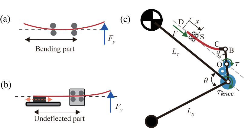
The mechanism of the VLLSA-leg for modeling is depicted in Fig. 2c: the red line represents the leaf-spring, the blue disks denote the gear set, the legged robot consists of the robot thigh segment , shank segment , crank shaft BO, connect hinge BC, leaf spring CD, and a position-controlled slider S which adjusts the effective length of the spring. Assuming that the leaf-spring deforms in a small-deflection range, the output torque, output stiffness, and the force exerted by the stiffness motor are given as [23]:
| (1) |
| (2) |
| (3) |
where is the length of leaf-spring, denotes Young’s modulus, denotes the area moment of inertia, is the leaf-spring deflection angle, is the output torque, is the slider position, and are the length of OB and BC, i.e., the lengths of the lever arms connecting the spring to the output link.
The models presented in (1)-(3) provide analytical expressions with parameters of the deflection angle and the slider position . Effectiveness of the model with small deflections has been verified in [23]. In next section, we will analyze the theoretical model and verify the derived properties of the proposed VLLSA with real-world experiments.
III Experimental Validation of VLLSA model
III-A Test platform
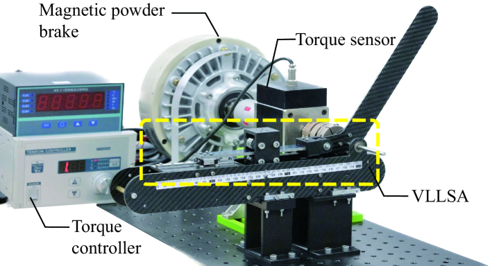
To validate properties of the proposed VLLSA, we have built an experimental platform, as is shown in Fig. 3. The output shaft of the VLLSA is connected to a torque sensor with the measuring range of [0, 50] Nm; a magnetic powder brake is connected to the other side of the torque sensor to provide resistance moment. This test platform will be used to test the stiffness modulation range in Section III-B, stiffness modulation speed in Section III-C and power consumption of VLLSA in Section III-D.
III-B Stiffness modulation range
Theoretical Analysis: Based on the nonlinear relationship between the output stiffness and the slider position in (2), the compact design can realize a wide range of stiffness by changing the effective length of the leaf-spring. When the slider is close to hip joint,
given , we have , i.e., the output stiffness is close to zero. When the slider is close to the knee joint, i.e., ,
the output stiffness tends to be infinite, and the output link becomes rigidly connected to the frame of the actuator. Therefore, given , the output stiffness range is:
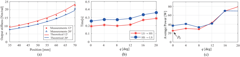
Experimental Validation: To test the stiffness modulation range in VLLSA, we select two deflection angles within the operational range of leaf spring for instance. Within a certain range of slider movement, if is too small, the stiffness variation will be insignificant; if is too large, the stiffness variation will be difficult to measure. Taking into account the practical structural design, under constant , the roller slider is moved from mm to mm to measure variation of the output stiffness, during which the output stiffness and slider position are recorded. The experiment is repeatedly conducted three times to ensure the consistency, the measured results are summarized in Fig. 4a.
We use red star and blue triangle to denote experimental results, red and blue lines to denote the theoretical values predicted by (2). It is clearly shown that the measured output stiffness aligns with the theoretical predictions. Within the high-stiffness domain, significant stiffness variations can be achieved by changing the effective spring length. For instance, when the deflection angle of the leaf-spring is and the slider moves from mm to mm, the output stiffness increases from 9.43 Nm/rad to 22.55 Nm/rad, by a ratio of 239%. Besides, we note that the three repeated trials shows high consistency, that the starts and triangles are almost overlapped at every measurement point; such consistency ensures the robustness of the open-loop control.
While the alignment between experimental data and theoretical predictions is observed, we also note that there are small error between the measured and model-predicted results, especially when the slider approaches to the knee joint, i.e., mm. This might be caused by the inevitable nonlinearity in the leaf spring, manufacturing error and the deformations in delicate system components. However, despite the small error, the legged robot can still operate successful hopping locomotion with open-loop controlled VLLSA, demonstrating the validity and robustness of the proposed model in (2).
III-C Stiffness modulation speed
Theoretical Analysis: To simplify the analysis, we assume that the deflection angle is constant, i.e., , the speed of stiffness modulation could be expanded as
| (4) |
where the first term in the right-hand side is determined by the mechanical design and could be derived from equation (2), and the second term simply refers to the movement speed of the slider driven by the ball screw, then we can rewrite (4) as
| (5) |
where is the lead of ball-screw, denoting the displacement of the slider when the motor rotates one circle, and is the rotational speed of stiffness motor.
Analyzing (5), we find that when the slider moves close to knee joint, i.e., , (5) gives
| (6) |
i.e., the speed of stiffness modulation keeps increasing to infinitely when the slider approaches to knee joint.
Besides, we note that when the mechanical design and the operation of legged robot are fixed, when is small, approximately, in (5) is linearly proportional to , the rotational speed of stiffness motor. This provides an intuitive method to control the stiffness modulation speed: changing the speed of stiffness motor could control the stiffness modulation speed; if the stiffness motor is set as constant speed, then stiffness variation during robot operation would be nearly consistent. Such property is important to legged robot in repetitive tasks such as hopping [33].
Experimental Validation: We mainly test the consistency in repetitive stiffness modulation, which is vital for the legged robotic systems. The stiffness motor is controlled at 2000 rpm with a constant voltage of 24 V. We select several sampled deflection angles ; under each angle, we control the slider to move back and forth between Low Stiffness (LS, mm) and High Stiffness (HS, mm) modes, and measure the stiffness modulation time, starting from the commanded start of motor and ending when the slider reaches the target position. The experiment results are presented in Fig. 4b.
We first observe that the stiffness variation of HSLS takes longer time than LSHS, this is mainly due to the measurement mechanism: the starting of measurement is set at the stiffness motor is commanded to rotate, and because the static friction of HS is larger than LS due to the pressure from leaf spring, the stiffness motor would take longer time to move the slider. Besides, it is clearly shown in Fig. 4b that the stiffness modulation speed is consistent across the same operation: when the deflection angle is small, , the time spent in HSLS and LSHS is around 0.28s and 0.2s; when the deflection angle is larger, , the stiffness modulation time increases to around 0.35s and 0.29s due to the increased resistance from leaf spring.
III-D Stiffness modulation power
Theoretical Analysis: The total electrical power required to modulate the stiffness consists of two parts: the power to drive the slider and the power to deform the leaf-spring.
| (7) |
where is the baseline power required to drive the ball-screw mechanism, no matter the deformation of the spring, the energy used for the driving mechanism is inevitable; is the power required to overcome the resistance from the leaf-spring’s deformation and hold the stiffness.
According to the ball-screw mechanism [34]:
where is the output force of stiffness motor, is the efficiency of the ball-screw driven system, is the output torque of stiffness motor. So, is bounded depending on and . In our particular configuration, the motor stiffness operates at a constant rotational speed. The power demand can be reduced with slower motor movement, while it will increase with a faster motor rotation.
Based on (3), the power required to hold the stiffness is
As the function (3) indicates, when the robot leg extends to the initial equilibrium configuration, i.e., , , then the required power to hold the stiffness is
This feature ensures that, at the initial equilibrium configuration, the motor can adjust the stiffness of the actuator without being opposed by the spring. When the robot leg is not at the initial equilibrium configuration, i.e., , the actuator’s ability to achieve infinite-range stiffness modulation is primarily constrained by its physical limitations. When , the stiffness is below a certain constrained value. The maximum power required to hold the stiffness is
Therefore, the total electrical power in (7):
| (8) |
it remains bounded regardless of the joint deflection and the stiffness. It is clear that the VLLSA can provide low modulation power while modulate a wide range of output stiffness when operated at a specific angle.
Experimental Validation: The experiment we conducted to verify the stiffness modulation power is to measure the consumed electric power of stiffness motor, as it is the only part that requires power input to VLLSA. The test is to measure the consumed power when the slider is moving back and forth between Low Stiffness (LS, mm) and High Stiffness (HS, mm), as is the setting when measuring the stiffness modulation speed in Section III-C.
When the leaf-spring is at its initial equilibrium position (). The Maxon motor drives the slider from LS to HS (marked by the red star in Fig. 4(c)), the baseline electrical power is calculated to be W (marked in Fig. 4(c) ). Compare with LS HS, the slider moves from HS LS (marked by the blue circle in Fig. 4(c)), the power consumed is higher because the slider should overcome the static friction. We notice that the angle varies within the range of , the power required for stiffness modulation is limited and remains nearly constant, the result is consistent with the in 3. When , the angle is relatively large, whether the slider moves forward or backward, the total power increases by a factor of (see Fig. 4(c)). This amplified power accounts for the energy needed to maintain stiffness and induce spring deformation.
| Actuator | Stiffness range [Nm/rad] | Average time to change stiffness [s] | Average speed of stiffness modulation [Nm/(rads)] | Stiffness modulation power [W] | Weight [Kg] | Size [] |
| VLLSA | [10, 1787] | 0.81 | 2194 | 24.50 | 0.45 | |
| HVSA [35] | [0, 120] | 0.16 | 750 | - | 1.80 | |
| VSSA[23] | [10, 7800] | 0.78 | 9990 | 8.20 | 3.00 | |
| Swi-CA[24] | [0.15, 3873] | 0.07 | 6504 | 1.64 | 2.36 |
III-E Comparison
To highlight the advantages of VLLSA, we have compared with other state-of-the-art alternatives, in terms of stiffness modulation range, speed, power consumption, weight and size. The results are summarized in Table II.
We first note that the HVSA (Hybrid Variable Stiffness Actuator) could change the stiffness based on an adjustable moment-arm mechanism with a dual-motor drive module. HVSA has the lowest weight and installation size, except VLLSA; but it has the relatively low stiffness modulation speed, which is important for hopping motion to release a large amount of energy in a short time. Further, we find that the VSSA (Variable Stiffness Spring Actuators) [23] and Swi-CA (Switchable Compliant Actuator) [24] could achieve high speed stiffness modulation with low energy cost due to their utilization of leaf springs [28]. VSSA adopts a conventional cantilever beam configuration to change the effective length of the leaf-spring, it could offer the highest stiffness modulation speed and largest variation range; Swi-CA integrates a variable stiffness spring module with a parallel elastic component. The parallel elastic element predominantly supplies the necessary torque at the output for sustaining the desired motion. This feature provide rapid response to stiffness variation with lowest power. However, it is their self-weight and dimension that constraint their applications in legged robotic systems.
In contrast, the proposed VLLSA has the lowest weight and size, relatively high stiffness modulation speed, its performance in Table. II is obtained by moving the slider from 35mm to 140mm, such characters make it suitable for the application in hopping motion. Although it requires the highest stiffness modulation power, the total energy consumed in the hopping motion is acceptable due to the short operation time of stiffness modulation, when compared to the whole duration of hopping. This will be demonstrated in the hopping experiments, as will be presented in Section V.
Summary: In this section, it is demonstrated that the model (1)-(3) provided in Section II-C could provide precise modeling of the output stiffness of the proposed VLLSA, as is demonstrated in Section III-B; in Section III-C-III-D, the analytical properties of the stiffness modulation speed and power are derived, analyzed and verified with hardware experiments. We have also compared the proposed VLLSA with other alternatives to highlight our advantages: with smaller installation size and self-weight, the VLLSA could provide large stiffness modulation range, fast modulation speed, while consume less power. This makes VLLSA suitable for legged robots.
Besides, it is revealed in Fig. 4b-c that the VLLSA has consistent and energy-efficient performance when is under small deflection. As changes from to , the knee joint angle is allowed to change from to due to the amplification of gear set, where is the minimum limit angle of knee joint. In the hopping experiment, we will control the robot motion such that the robot operates within this range to achieve the best dynamic performance.
IV Hopping Control Strategy
We have investigated the design and dynamic properties of the VLLSA in Sections II–III. To test the performance of VLLSA in legged robot, we implement the typical virtual model control (VMC) [36] to formulate a PD-like feedback controller for hopping task. In this section, we will briefly present the VMC method formulated for the legged robot system with VLLSA.
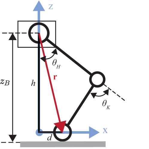
We define the following generalized coordinate variable for the legged robot system with VLLSA
where is the base height from the ground, is the hip joint angle and is the knee joint angle, as are shown in Fig. 5.
In the repetitive hopping task, the legged robot dynamics could be divided into two phases: stance and flight. We first consider the dynamics in stance mode, i.e., the foot is in contact with the ground. The contact dynamics of the system can be expressed in the closed form as
| (9) | |||
where is the joint space inertia matrix (JSIM), is the collection of nonlinear effects including Coriolis and generalized gravity, is the output torque from hip and knee joints, is the contact Jacobian matrix and is the point-contact force.
To control the robot, we implement the VMC method which regards the robot as a spring-damper system with respect to the state variables
where are respectively x and z-axis distance of the foot contact frame with respect to the hip frame, as shown in Fig. 5. Input to the spring-damper system is a virtual force
| (10) |
where is the virtual force exerted in x and z-axis direction, is the desired position, and are two matrices defining the stiffness and damping of the virtual model.
The VMC method [36] sets the joint torques to
| (11) |
where is the virtual contact point Jacobian and is the estimated contact force. For convenience, we set the virtual contact point to be the same as the foot contact point, i.e., , and the is set as where is the total mass of the robot from sketch and . Substituting (11) into (9), one can derive the contact dynamics with VMC controller:
where is the base nonlinear effect, i.e., Coriolis force and gravity, and are the base and joint columns of the contact jacobian. Assuming accurate approximation, i.e., , the virtual model dynamics as a function of is then controlled by the PD-like virtual contact force in (10), simulating a spring-damper system where the reactive force is linearly proportional to the displacement and velocity.
When the robot is off-ground in flight mode, the contact force is zero and the VMC-controlled dynamics could be simplified as
We note that the torque applied to knee joint combines the output from both VLLSA and motor, thus saving the power of the knee joint motor. Consequently, to implement the VMC method, the torque required from the hip and knee motors could be computed by
| (12) |
where is the output torque of VLLSA at knee joint.
One of the advantages when using the VMC controller in (10) is that it only requires the feedback parameters and , both of which could be evaluated directly using the angles and measured by the encoder in the joint motor. Consequently, the height is not required by the controller, eliminating the influence from environment and making the VLLSA-leg a self-contained robotic system.
We note that the principles of VMC assume the model to have concentrated inertia on the non-rotating link; however, the slider in VLLSA cannot guarantee such assumption. As will be shown later in the experiments, the robot cannot precisely control the x-axis position during the highly dynamic aerial phase of the hopping; but as the paper is to demonstrate the effectiveness of VLLSA, such deviation is relatively acceptable.
V Hopping experiment and results
V-A Experimental setup
Task setting: Our experiment examine a highly dynamic hopping task with active leg retraction during the entire cycle from jumping to landing, where the scenario of such task is to jump over an obstacle with the leg retracted during the hopping motion. Locomotion of the legged robot is controlled using the VMC controller defined in (10), while the VLLSA is controlled to provide supporting torque with variable stiffness using the open-loop control model in (1). In the experiment we control the robot to accelerate for first two steps and then in the third jump, the leg will retract to generate the best height for hopping over obstacles.
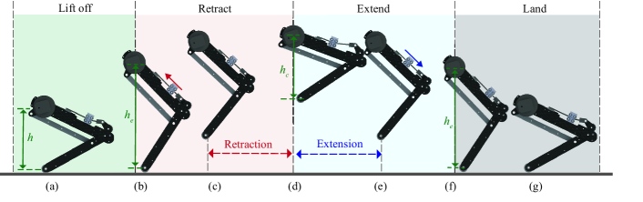
Control strategy of the legged robot: Our hopping strategy aims to increase the distance between the foot and the ground, allowing the legged robots to perform more challenging tasks and adapt to complex, unpredictable environments. To realize the highly dynamic hopping task, the controller is designed to be event-triggered. Once the jump command is given, the feedback gains in (10) are set as high and low to track the predefined extension height . Once is reached, the controller in (10) switches to high and to hold and the VLLSA switches to low stiffness for compliant motion. Then the robot contracts the knee to a contraction height , where , to skip over the obstacle; afterwards, the height is extended to and VLLSA switches to high stiffness to prepare landing. The controller detects the landing event using the deviation of the current and predefined value for landing impact buffering. Upon the detection of landing contact, the controller switches back to moderate and for compliant landing. The hopping trajectory of the VLLSA legged robot is illustrated in Fig. 6.
Control strategy of VLLSA: We note that our target of introducing VLLSA is to save the power provided by the knee motor. Subsequently, we control the VLLSA with following strategy: the legged robot takes off with high stiffness to save raising power, retracts in flight with low stiffness for ease robot motion, and lands with high stiffness to provide extra supporting torque. The hopping control strategy in VS mode is marked in Fig. 6 with red and blue arrows. We note that most of the prior hopping experiments with VSAs [20, 25, 37, 38] focused on studying the natural dynamics of passive hopping behaviors, while our experiments adopt the active hopping locomotion for better dynamic performance.
Hardware setup: To simplify the hopping motion and focus on investigating the performance of the proposed VLLSA in legged robot, we conducted an in-place hopping experiment with the VLLSA-leg shown in Fig. 1. The hip of the legged robot is mounted on a linear guide to ensure the hip moving vertically in a linear pattern. The hardware setting is shown in Fig. 7a-d.
V-B Experimental results
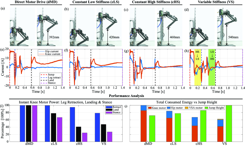
To highlight the advantages of VLLSA, we design four sets of hopping experiments with different actuation methods: 1) Direct Motor Drive (dMD) where the VLLSA is disconnected with the knee joint; 2) Constant Low Stiffness (cLS) where the slider is kept at low stiffness position; 3) Constant High Stiffness (cHS) where the slider is kept at high stiffness position; and 4) Variable Stiffness (VS) where the slider is controlled to move and output torque with variable stiffness. The control strategy of VLLSA in VS mode is presented in Section V-A. To keep the consistency across different actuation methods, all the hopping tests are initialized with the same initial state and the same control parameters in VMC controller (10). We record the current of the knee/hip-joint motor for each method, the results are analyzed below and presented in Fig. 7 and the supplementary video.
V-B1 Hopping performance
As the task is to imitate jumping over obstacles, the hopping performance is evaluated by the lifting height of the foot. The observed hopping heights is presented in Fig. 7a-d for the four actuation methods. We note that 1) dMD mode achieves the lowest height due to the lack of extra support from leaf spring, 2) although the cLS mode could only provide a small output torque with low stiffness, it could help jump higher than dMD, and 3) the cHS jumps higher than cLS as higher output stiffness could provide more kinetic energy accumulation. Such phenomenon coincides with the previous works that the compliant actuators in legged robot could improve the hopping performance [39, 40]. The VS mode achieves the highest jumping: 37.8% higher than the dMD because the high knee stiffness could accumulate more kinetic energy, and 17.4% higher than the cHS because the low stiffness in flight could ease the leg retraction. Consequently, it is demonstrated that the legged robot with compliant VLLSA could improve the performance in dynamic hopping tasks.
V-B2 Dynamic motion analysis
The measured currents during hopping in hip and knee motors are displayed in Fig. 7e-h. We define the duration between jumping (red dashed line), leg retraction (blue dashed line), and landing (black dashed line) as , .
Comparing the dMD and cLS in Fig.7e,f, we note that the , in dMD and cLS are almost identical, because the stiffness in cLS mode is quite low and has little influence on the hooping motion.
Comparing the cLS and cHS in Fig. 7f,g, we note that due to the larger output stiffness and higher acceleration; also, it is observed that , as the knee motor need to overcome the large stiffness in cHS mode to retract the leg, so the high stiffness in knee is undesirable when retracing the leg. Consequently, it is expected that the legged robot would have high stiffness when jumping, and low stiffness when retracting the leg, corresponding to the operation in VS mode.
Comparing the cHS and VS in Fig. 7g,h, we note that is approximately the sum of and : the jumping process to is also the same between cHS and VS, as they both drive in high stiffness mode; in the air, the robot waits for the change to low stiffness to ease the leg retraction, thus extending the . Also, we observed that is close to , as the output stiffness when retracting leg is the same as cLS mode to save energy consumption. In summary, the VS mode integrates the advantages of high stiffness when jumping and low stiffness when retracting leg, thus provide the best performance when compared to other alternative methods.
V-B3 Instant motor power
We mainly consider two aspects regarding energy consumption: instant motor power and total energy consumption during hopping.
The peak instant motor power marks the largest power supplied by the motor to the system, requiring large power output might damage the motor or deteriorating the dynamic performance of the hopping motion; thus, we would expect the peak motor power would be reduced. During the hopping, the sharp increase of motor power appears in knee motor at jumping and leg retracting moment, the analyzed data is presented in Fig. 7i.
We first note that the instant power at leg retraction, denoted by the blue bar in Fig. 7i, is decided by two factors, stiffness at knee joint and the angular velocity of lower leg: large stiffness at knee joint would consume more power, small angular velocity of lower leg would also require more instant power to lift the leg. Consequently, we note that dMD and cLS requires the highest instant power due to the low angular velocity to lift the lower leg, cHS requires less power due to the high velocity when retracting the leg, and VS mode requires the least power because 1) the lower leg has high speed as cHS, and 2) the knee stiffness has lower stiffness.
During robot landing, we note dMD has the highest instant power (denoted by the black bar in Fig. 7i) due to the lack of compliant supporting, though it has the lowest jumping height; the cLS only requires 80% instant power compared to dMD due to the introduction of VLLSA, even with low stiffness. The instant landing power in cHS and VS is almost the same, VS is slightly higher as it has larger jumping height. Similar conclusion holds in static stance, denoted by the purple bar in Fig. 7i, as the static power in stance is mainly decided by the knee stiffness: larger stiffness would require less motor power to support the legged robot.
V-B4 Total energy consumption
Next we analyze the total energy consumption during hopping. It is expected that the energy consumption could be reduced as most of the mobile robotic systems are driven by batteries, saving energy would extend the duration of robot operation. It is obvious that dMD mode consumes the most energy as all the robot motion is driven by the hip and knee motors; the cLS mode saves energy to dMD as the leaf spring help support the robot during landing and static stance; the cHS mode consumes lower power than cLS as it further saves energy during jumping and static stance by providing larger output stiffness. The VS mode changes the stiffness to further save power during leg retraction when compared to cHS; finally the VS mode provides the best hopping performance while consuming the least electric power. This clearly demonstrates the advantages of variable stiffness by introducing VLLSA in legged hopping robots.
In summary, the presented experimental results in this section clearly demonstrate that, the proposed VLLSA could actively change the output stiffness in knee joint to integrate the advantages of low stiffness in compliant motion, like leg retraction, and high stiffness in explosive motion, like jumping and landing. Furthermore, integration of VLLSA could reduce the instant motor power to protect the electronic components, and save the total energy consumption to extend the operation of battery-powered mobile robots.
VI Conclusion
In this paper, we have proposed a novel variable stiffness actuator for legged robot. The proposed VLLSA changes the output stiffness by changing the effective length of the leaf spring. We note that the VLLSA is compact and lightweight for a legged robot; when compared to other alternatives, it could provide variable output stiffness with wider range, fast speed and lower energy consumption. Furthermore, we have validated the design and advantages of VLLSA with real-world hopping experiments; the experimental results indicate that hopping locomotion with VLLSA reduces the energy consumption by 38% and improves jumping height by 37.76% when compared to other alternatives. Our future work would focus on optimizing the design parameters to improve the energy efficiency and developing data-driven control methods to improve the hopping locomotion in real-world environment [33, 36, 41, 42].
References
- [1] R. U. Newton, W. J. Kraemer, K. Häkkinen, B. J. Humphries, and A. J. Murphy, “Kinematics, kinetics, and muscle activation during explosive upper body movements,” Journal of applied biomechanics, vol. 12, no. 1, pp. 31–43, 1996.
- [2] A. M. Wilson, J. C. Watson, and G. A. Lichtwark, “A catapult action for rapid limb protraction,” Nature, vol. 421, no. 6918, pp. 35–36, 2003.
- [3] K. C. Galloway, J. E. Clark, and D. E. Koditschek, “Variable stiffness legs for robust, efficient, and stable dynamic running,” Journal of Mechanisms and Robotics, vol. 5, no. 1, p. 011009, 2013.
- [4] Y. Huang et al., “Step length and velocity control of a dynamic bipedal walking robot with adaptable compliant joints,” IEEE/ASME Trans. Mechatron., vol. 18, no. 2, pp. 598–611, 2013.
- [5] L. Liu, S. Leonhardt, C. Ngo, and B. J. Misgeld, “Impedance-controlled variable stiffness actuator for lower limb robot applications,” IEEE Transactions on Automation Science and Engineering, vol. 17, no. 2, pp. 991–1004, 2019.
- [6] A. Jafari, N. G. Tsagarakis, and D. G. Caldwell, “Awas-ii: A new actuator with adjustable stiffness based on the novel principle of adaptable pivot point and variable lever ratio,” in Proceedings of the IEEE International Conference on Robotics and Automation, Shanghai, China, pp. 4638–4643.
- [7] M. Grimmer, M. Eslamy, S. Gliech, and A. Seyfarth, “A comparison of parallel-and series elastic elements in an actuator for mimicking human ankle joint in walking and running,” in Proceedings of the IEEE International Conference on Robotics and Automation, Minneapolis (MN), USA, 2012, pp. 2463–2470.
- [8] M. Hutter, C. D. Remy, M. A. Hoepflinger, and R. Siegwart, “Scarleth: Design and control of a planar running robot,” in Proceedings of the IEEE/RSJ International Conference on Intelligent Robots and Systems, San Francisco, (CA), USA, 2011, pp. 562–567.
- [9] M. Hutter, C. Gehring, A. Lauber, F. Gunther, C. D. Bellicoso, V. Tsounis, P. Fankhauser, R. Diethelm, S. Bachmann, M. Blösch et al., “Anymal-toward legged robots for harsh environments,” Advanced Robotics, vol. 31, no. 17, pp. 918–931, 2017.
- [10] C. Hubicki, J. Grimes, M. Jones, D. Renjewski, A. Spröwitz, A. Abate, and J. Hurst, “Atrias: Design and validation of a tether-free 3d-capable spring-mass bipedal robot,” The International Journal of Robotics Research, vol. 35, no. 12, pp. 1497–1521, 2016.
- [11] J. Sun et al, “A novel design of serial variable stiffness actuator based on an archimedean spiral relocation mechanism,” IEEE/ASME Transactions on Mechatronics, vol. 23, no. 5, pp. 2121–2131, 2018.
- [12] Y. Yesilevskiy, W. Xi, and C. D. Remy, “A comparison of series and parallel elasticity in a monoped hopper,” in Proceedings of the IEEE International Conference on Robotics and Automation, Seattle (WA), USA, 2015, pp. 1036–1041.
- [13] J. Wu et al., “Design and validation of a novel leaf spring-based variable stiffness joint with reconfigurability,” IEEE/ASME Trans. Mechatron., vol. 25, no. 4, pp. 2045–2053, 2020.
- [14] S. Wang, W. van Dijk, and H. van der Kooij, “Spring uses in exoskeleton actuation design,” in Proceedings of the IEEE International Conference on Rehabilitation Robot, Zurich, Switzerland, 2011, pp. 1–6.
- [15] E. Ambrose and A. D. Ames, “Improved performance on moving-mass hopping robots with parallel elasticity,” in Proceedings of the IEEE International Conference on Robotics and Automation, Paris, France, 2020, pp. 2457–2463.
- [16] Z. Batts, J. Kim, and K. Yamane, “Design of a hopping mechanism using a voice coil actuator: Linear elastic actuator in parallel (leap),” in Proceedings of the IEEE International Conference on Robotics and Automation, Stockholm, Sweden, 2016, pp. 655–660.
- [17] T. Verstraten, P. Beckerle, R. Furnémont, G. Mathijssen, B. Vanderborght, and D. Lefeber, “Series and parallel elastic actuation: Impact of natural dynamics on power and energy consumption,” Mechanism and Machine Theory, vol. 102, pp. 232–246, 2016.
- [18] P. Beckerle, T. Verstraten, G. Mathijssen, R. Furnémont, B. Vanderborght, and D. Lefeber, “Series and parallel elastic actuation: Influence of operating positions on design and control,” IEEE/ASME Transactions on Mechatronics, vol. 22, no. 1, pp. 521–529, 2016.
- [19] M. A. Sharbafi, M. J. Yazdanpanah, M. N. Ahmadabadi, and A. Seyfarth, “Parallel compliance design for increasing robustness and efficiency in legged locomotion - proof of concept,” IEEE/ASME Transactions on Mechatronics, vol. 24, no. 4, pp. 1541–1552, 2019.
- [20] H. Q. Vu, X. Yu, F. Iida, and R. Pfeifer, “Improving energy efficiency of hopping locomotion by using a variable stiffness actuator,” IEEE/ASME Transactions on Mechatronics, vol. 21, no. 1, pp. 472–486, 2016.
- [21] F. Bjelonic, J. Lee, P. Arm, D. Sako, D. Tateo, J. Peters, and M. Hutter, “Learning-based design and control for quadrupedal robots with parallel-elastic actuators,” IEEE Robotics and Automation Letters, vol. 8, no. 3, pp. 1611–1618, 2023.
- [22] Á. Belmonte-Baeza, J. Lee, G. Valsecchi, and M. Hutter, “Meta reinforcement learning for optimal design of legged robots,” IEEE Robotics and Automation Letters, vol. 7, no. 4, pp. 12 134–12 141, 2022.
- [23] D. J. Braun, V. Chalvet, T.-H. Chong, S. S. Apte, and N. Hogan, “Variable stiffness spring actuators for low-energy-cost human augmentation,” IEEE Transactions on Robotics, vol. 35, no. 6, pp. 1435–1449, 2019.
- [24] W. Shin and J. Kim, “Switchable compliant actuator with fast stiffness modulation and energy efficient power transmission,” Mechatronics, vol. 90, p. 102929, 2023.
- [25] F. Guenther, H. Q. Vu, and F. Iida, “Improving legged robot hopping by using coupling-based series elastic actuation,” IEEE/ASME Transactions on Mechatronics, vol. 24, no. 2, pp. 413–423, 2019.
- [26] M. K. Shepherd and E. J. Rouse, “The vspa foot: A quasi-passive ankle-foot prosthesis with continuously variable stiffness,” IEEE Transactions on Neural Systems and Rehabilitation Engineering, vol. 25, no. 12, pp. 2375–2386, 2017.
- [27] H. F. Lau, A. Sutrisno, T. H. Chong, and D. J. Braun, “Stiffness modulator: A novel actuator for human augmentation,” in Proceedings of the IEEE International Conference on Robotics and Automation, Brisbane, Australia, 2018, pp. 7742–7748.
- [28] V. Chalvet and D. J. Braun, “Algorithmic design of low-power variable-stiffness mechanisms,” IEEE Transactions on Robotics, vol. 33, no. 6, pp. 1508–1515, 2017.
- [29] S. Seok et al., “Design principles for energy-efficient legged locomotion and implementation on the mit cheetah robot,” IEEE/ASME Transactions on Mechatronics, vol. 20, no. 3, pp. 1117–1129, 2014.
- [30] J. Shigley, C. R. Mischke, R. G. Budynas et al., Mechanical Engineering Design. New York: Mc Graw-Hill, 1972.
- [31] R. Chaichaowarat, S. Nishimura, and H. I. Krebs, “Design and modeling of a variable-stiffness spring mechanism for impedance modulation in physical human–robot interaction,” in Proceedings of the IEEE International Conference on Robotics and Automation, Xi’an, China, 2021, pp. 7052–7057.
- [32] D. J. Braun, V. Chalvet, and A. Dahiya, “Positive–negative stiffness actuators,” IEEE Transactions on Robotics, vol. 35, no. 1, pp. 162–173, 2019.
- [33] Y. Chen, Y. Li, and D. J. Braun, “Data-driven iterative optimal control for switched dynamical systems,” IEEE Robotics and Automation Letters, vol. 8, no. 1, pp. 296–303, 2022.
- [34] C.-C. Wei and R.-S. Lai, “Kinematical analyses and transmission efficiency of a preloaded ball screw operating at high rotational speeds,” Mechanism and machine theory, vol. 46, no. 7, pp. 880–898, 2011.
- [35] B.-S. Kim and J.-B. Song, “Design and control of a variable stiffness actuator based on adjustable moment arm,” IEEE Transactions on Robotics, vol. 28, no. 5, pp. 1145–1151, 2012.
- [36] J. Pratt, C.-M. Chew, A. Torres, P. Dilworth, and G. Pratt, “Virtual model control: An intuitive approach for bipedal locomotion,” The International Journal of Robotics Research, vol. 20, no. 2, pp. 129–143, 2001.
- [37] B. Vanderborght, N. G. Tsagarakis, R. Van Ham, I. Thorson, and D. G. Caldwell, “Maccepa 2.0: compliant actuator used for energy efficient hopping robot chobino1d,” Autonomous Robots, vol. 31, pp. 55–65, 2011.
- [38] J. Hurst, J. Chestnutt, and A. Rizzi, “An actuator with physically variable stiffness for highly dynamic legged locomotion,” in Proceedings of the IEEE International Conference on Robotics and Automation, New Orleans, LA, 2004, pp. 4662–4667.
- [39] F. Nan, H. Kolvenbach, and M. Hutter, “A reconfigurable leg for walking robots,” IEEE Robotics and Automation Letters, vol. 7, no. 2, pp. 1308–1315, 2022.
- [40] X. Liu, A. Rossi, and I. Poulakakis, “Spear: A monopedal robot with switchable parallel elastic actuation,” in Proceedings of the IEEE/RSJ International Conference on Intelligent Robots and Systems, Hamburg, Germany, 2015, pp. 5142–5147.
- [41] A. H. Chang, C. M. Hubicki, J. J. Aguilar, D. I. Goldman, A. D. Ames, and P. A. Vela, “Learning terrain dynamics: A gaussian process modeling and optimal control adaptation framework applied to robotic jumping,” IEEE Transactions on Control Systems Technology, vol. 29, no. 4, pp. 1581–1596, 2021.
- [42] H. Chen, B. Wang, Z. Hong, C. Shen, P. M. Wensing, and W. Zhang, “Underactuated motion planning and control for jumping with wheeled-bipedal robots,” IEEE Robotics and Automation Letters, vol. 6, no. 2, pp. 747–754, 2021.