Thermal effect on microwave pulse driven magnetization switching of Stoner particle
Abstract
Recently it has been demonstrated that the cosine chirp microwave pulse (CCMP) is capable of achieving fast and energy-efficient magnetization-reversal of a nanoparticle with zero-Temperature. However, we investigate the finite temperature, effect on the CCMP-driven magnetization reversal using the framework of the stochastic Landau Lifshitz Gilbert equation. At finite Temperature, we obtain the CCMP-driven fast and energy-efficient reversal and hence estimate the maximal temperature, at which the magnetization reversal is valid. increases with increasing the nanoparticle cross-sectional area/shape anisotropy up to a certain value, and afterward decreases with the further increment of nanoparticle cross-sectional area/shape anisotropy. This is because of demagnetization/shape anisotropy field opposes the magnetocrystalline anisotropy, i.e., reduces the energy barrier which separates the two stable states. For smaller cross-sectional area/shape anisotropy, the controlling parameters of CCMP show decreasing trend with temperature. We also find that with the increment easy-plane shape-anisotropy, the required initial frequency of CCMP significantly reduces. For the larger volume of nanoparticles, the parameters of CCMP remains constant for a wide range of temperature which are desired for the device application. Therefore, The above findings might be useful to realize the CCMP-driven fast and energy-efficient magnetization reversal in realistic conditions.
I Introduction
Obtaining swift and efficient magnetization switching of a single nanoparticle has attracted much attention because of its non-volatility [1, 2, 3] and speedy data processing properties [4]. In the last decades, several controlling parameters, for instance, magnetic fields, microwaves fields [5, 6], spin-polarized electric current and spin-orbit torque [7, 8, 9, 10, 11, 12, 13, 14, 15, 16, 17, 18, 19, 20, 21] are employed to reverse magnetization reversal. However, these methods are facing specific challenging issues in memory-device applications. Particularly, in the case of the magnetic field, it requires a large field and a longer switching time [5]; also field localization to a bit-cell is a bottleneck. On the other hand, the spin-polarized-current can induce magnetization switching by the mechanism of spin transfer torque (STT) andor spin-orbit torque (SOT) [22, 23, 24, 25, 26, 27]. However, for STT-MRAM-based devices, the threshold current density is large and it creates Joule heat which, in turn, causes the device lifetime and reliability issues [28, 29, 30, 31, 32, 33, 34]. For SOT-MRAM-based device applications, the main hindrance is that the requirement of two transistors for each bit-cell enhances the area of the bit-cell [35]. Later on, people employ the microwave field with constant or time-dependent frequency profile to drive magnetization switching at zero temperature [36, 37, 38, 39, 40, 41, 42, 43, 44, 45, 46, 47, 48, 49]. However, without considering the thermal effect, the recent study [50] reported that the swift and energy-efficient magnetization switching is obtained by a cosine chirped microwave pulse (cosine CMP). This is because the frequency changing (of Cosine CMP) is closely matched with the magnetization precession frequency which leads to the stimulated energy absorption (emission) by magnetization efficiently before (after) crossing the energy barrier. However, in practice, the temperature is prevailing everywhere, and devices are operated at room temperature. So, from the practical point of view, it is interesting to verify whether the Cosine CMP still efficiently drives magnetization switching at finite temperature. In addition, the study [50] reported that the increase of easy-plane shape anisotropy (i.e., the increase of demagnetization field) makes the magnetization switching faster which is expected for device application. But, the increase of the demagnetization field (which opposes the magnetocrystalline anisotropy) reduces the height of the energy barrier, originated by anisotropy, which may cause thermal instability issues at roomoperating temperature. Thus at operating temperature, there is a possibility of spontaneous magnetization switching which may increase the error rate, which is actually undesired. Therefore, in this study, we include the finite/room temperature in the system and relax it, afterward we investigate the cosine CMP-driven magnetization switching to check whether the switching is robust at operating (room) temperature and how the parameters (i.e., the optimal initial frequency and field amplitude) of cosine CMP are altered with temperature.
This study interestingly finds that the cosine CMP-driven swift and energy-efficient switching is robust even with a finiteroom temperature. For the considered nanoparticlesstoner particle, we also estimate the maximal temperature, at which the magnetization is valid. increases with increasing the nanoparticle volume (by increasing cross-sectional area, ) or shape-anisotropy coefficient up to a certain value, and significantly decreases with the further increment of nanoparticle cross-sectional areashape-anisotropy coefficient. Here the demagnetizationshape anisotropy reduces the effective uniaxial anisotropy i.e., reduces the energy barrier which separates the two stable states. Still, the cosine CMP-driven magnetization switching is valid for a wide operating temperature above room temperature. For the smaller volume of nanoparticlesstoner particle, the controlling parameters of cosine CMP, i.e., the minimal amplitude (T), the optimal rate (GHz), and the minimal initial frequency (GHz) show a decreasing trend with temperature. We also find that with the increment of easy-plane shape-anisotropy, the required initial frequency of cosine CMP significantly reduces. For the larger volume of nanoparticles, the parameters of cosine CMP remain constant for a wide range of temperature that is desired for the device application. Note that this strategy might be employed to switch the magnetization of other materials, for instance, synthetic antiferromagnetic/ ferrimagnetic nanoparticles by in-plane cosine chirped current pulse via spin-orbit torque. Therefore, the above findings might be useful to realize the cosine CMP-driven fast and energy-efficient magnetization switching in practical spintronics device applications with considering realistic conditions.
II Model and Method
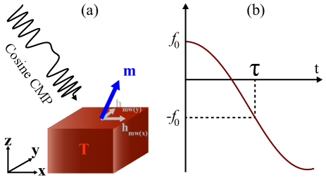
We assume a single-domain magnetic nanoparticle/Stoner particle of volume , where is the cross-sectional area and is thickness, and its uniaxial anisotropy is directed along axis at temperature , as shown in Figure 1(a). The nanoparticle’s size is chosen in such a way that the magnetization of can be treated as a macrospin which is indicated by the unit-vector with saturation magnetization . An easy-plane shape anisotropy is approximated the demagnetization field which is opposite to the magnetocrystalline anisotropy field.
The shape anisotropy field is indicated as , where is the shape anisotropy coefficient, and are demagnetization factors [51, 52] and is the vacuum magnetic permeability. The total anisotropy is dominated by the magnetocrystalline anisotropy and hence the magnetic particle possesses two stable states (i.e., the aligns parallel to and ).
At finite temperatures, the dynamics of magnetization are governed by the stochastic Landau Lifshitz Gilbert (sLLG) with the application of a circularly polarized cosine CMP [53].
| (1) |
where and are the Gilbert damping constant and the gyromagnetic ratio respectively. Additionally, the total magnetic field () consists of the effective field, which comes from the exchange field , and effective the easy-axis anisotropy field along direction, and the external microwave field ().
The stochastic thermal field is denoted by , which comes from a finite temperature. The thermal field exhibits the following relations which are described by the Gaussian process [54, 55].
| (2) |
where is the Boltzman constant, and are the Cartesian thermal field components, is the volume of a single micromagnetic cell, and and designate the micromagnetic cells. Depending on the temperature, the thermalrandom field is generated as
| (3) |
where is the time step and is a random vector which changes with time step and provides the normal distribution with zero average.
Without microwave field and with zero-temperature, there are two ground states (or energy minima) and in which the magnetization likes to stay due to uniaxial anisotropy. The main task is to switch the magnetization from one energy minima to another energy minima, purposely the study [50] reported that, at zero temperature, the cosine CMP is efficient to achieve fast switching. The cosine CMP is constructed as , where is microwave amplitude and is the phase. is denoted as , (in GHz) is the controlling parameter, and is the instantaneous frequency of cosine CMP, is defined as which sweeps from to final as shown in Figure 1(b). The physical picture of obtaining the fast and energy-efficient magnetization switching is that the cosine CMP induces stimulated microwave absorption (emissions) by (from) the macro-spin before (after) crossing over the energy barrier at zero temperature and, for detail, the formulation of the rate of energy change is given in the appendix [50]. In this study, we use the material parameters reported in Ref. [56], Am, = T or Jm3, , exchange constant = Jm, and to mimic Permalloy. This study shows a strategy that would work for other materials also since Permalloy does not possess such a high anisotropy [57, 58]. MuMax3 Package [59] has been used to solve the stochastic-LLG equation using the adaptive-Heun solver.
We study the nanoparticles by increasing the cross-sectional area while the thickness nm is kept constant. Particularly, the nanoparticles with the areas are nm2, nm2, nm2, and nm2 so that the demagnetization field is induced in the opposite direction of uniaxial anisotropy. We discretize the sample by the unit-cell size nm3. For efficient and stable calculation [60, 61], we employ the fixed time step of s. According to the practical requirement, we consider the switched state is obtained if the magnetization reaches at .
| Cross-sectional | Shape | Temperature, | Optimal | Minimal initial | Minimal |
|---|---|---|---|---|---|
| area, | anisotropy, | (K) | rate, | frequency, | Amplitude, |
| (nm2) | (T) | (GHz) | (GHz) | (T) | |
| 0 | = 0 | 17.22 | 18.8 | 0.0450 | |
| = 300 | 15.12 | 18.8 | 0.0445 | ||
| = 1000 | 16.38 | 18.7 | 0.0439 | ||
| 0.17718 | = 0 | 17.64 | 17.7 | 0.0450 | |
| = 300 | 16.38 | 17.7 | 0.0450 | ||
| = 1400 | 14.28 | 17.6 | 0.0447 | ||
| 0.3064 | = 0 | 17.22 | 13.5 | 0.0450 | |
| = 300 | 16.8 | 13.1 | 0.0450 | ||
| = 1500 | 15.96 | 13.5 | 0.0447 | ||
| 0.4459 | = 0 | 27.3 | 7.7 | 0.0450 | |
| = 300 | 27.3 | 7.1 | 0.0450 | ||
| = 800 | 27.3 | 6.3 | 0.0450 |
III Numerical Results
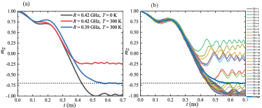
Firstly we investigate the magnetization switching of the nanoparticle nm3 driven by cosine CMP with the initial frequency GHz and the microwave field T, which are similar parameters to the study [50] for K. By keeping GHz and T fixed, then we try to determine the optimal (at which the switching is fastest) which is obtained GHz for . Then we include the temperature and relax the system. Afterward, we apply the cosine CMP to the system and study the switching at finite temperatures. In principle, we simulate 30 independent switchings by varying the random numbersthermseeds for the same parameters of material and of cosine CMP ( GHz, T and GHz) and take the ensemble average as shown in figure 2 (b). In this way, we estimate each observationsdata points of this study. Now for K, we study the system nm3 by cosine CMP with the parameters ( GHz, T and GHz), but the switching is not obtained as expected which shown by the red line in the 2(a). Then is optimized (for fixed GHz and T), and for the optimal GHz, we find the fastest magnetization switching as shown by the blue line in Figure 2 (a). Therefore, it is noted that optimal depends on temperature, which is a crucial issue that needs to be addressed for realistic applications.
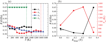
It is reported that, with enlarging the volume of the samplesnanoparticles sizes, the thermal stability () increases since the anisotropy energy, (, is effective anisotropy coefficient) is proportional to volume, which increases the energy barrier [62, 63, 64, 65, 66] but thermal energy does not depend on volume. In this study, we focus on the samples with increasing cross-sectional area while the thickness nm is kept constant so that the volume () is enlarged. Specifically, our considered samples are with , , and nm2 while the thickness nm is fixed. Therefore, in these sample shapes, the demagnetization fieldshape anisotropy (which is the opposite of the crystalline anisotropy) would be induced because of the magnetization of the nanoparticle. For different , by finding the demagnetization-factors and [51, 67] analytically, the shape anisotropy of the samples has been calculated. So, shape anisotropy are T, T, T and T, for , , and respectively. The actually opposes the anisotropy field and reduces the stability as well as resonance frequency . Therefore, there is an issue to study how increment of the shape anisotropy, as well as the volume of the sample, affect the thermal stability and the parameters of cosine CMP. Purposely, we investigate the cosine CMP-driven magnetization switching of the patterned samples of , , and by varying and estimate optimal for different . Fig 3(a) demonstrates the change of optimal as a function of thermal effect, for different samples. Optimal shows a decreasing trend for lower (smaller cross-sectional area) , albeit with some fluctuation. However, for higher , optimal is larger (the magnetization switching is faster) and remains constant with . For each sample, there is a maximal temperature for which the magnetization switching is valid, which is indicated by the vertical dashed line in Figure 3(a). ’s are higher than the room temperature. The above findings are useful for device applications. In Fig 3(b), we explicitly plot and optimal at as a function , it is found that decreases till a certain value of and for further increment of , increases significantly, i.e., the switching time becomes smallest. The reason can be attributed as (using basic knowledge) the effective saturation magnetization decreases with temperature because of the spin-wave generation [68]. For , and , i.e., smaller volume, decreases faster with refers to the study [69], so optimal decreases as a function of with some fluctuations, which might be absent if one can take a large number of ensemble average, and the change of optimal with would be more consistent. However, for larger , i.e., larger volume, the decrement of with is not significant, so optimal remains constant. For , and , increases because of the increment of the sample volume, rather than as it is not dominant, which plays a role to increase the thermal stability. But for the larger , becomes dominant and it reduces the uniaxial anisotropy as well as the energy barrier which separates the two stable states. This is why thermal stability decreases, i.e., decreases significantly.
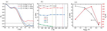
Subsequently, we determine the optimal of cosine CMP, with the investigation of magnetization switching, with by keeping amplitude T and the optimal for corresponding fixed. Figure 4(a) shows the magnetization switching (black line) induced by cosine CMP with T, GHz, and GHz for = 0 K, but at = 300 K, the magnetization switching (red line) is no longer valid with these parameters. Then we tune by keeping T and optimal (at = 300 K) fixed and we obtain magnetization switching (blue line) with GHz. Then for different or samples, we investigate the variation of with and demonstrate in Figure 4(b). With increasing the , the initial frequency decreases significantly, which is expected as the actually acts in the opposite direction of the and thus decreases as shown in the Figure 4 (a). For the samples of T, 0.17718 T and 0.3064 T, minimal remains almost constant up to a maximal temperature which is useful for practical device realization. But, for the sample of T, optimal shows a decreasing trend. This is because of the reduction of effective (since the demagnetization field is strong), which leads to a decrement of intrinsic frequency as well. As a result, all dynamics become slow, as though the time scale of the magnetization dynamics has been expanded. Explicitly, and optimal at as a function of are plotted in the Figure 4(b), it is observed that initially increases up to certain temperature and then decreases rapidly for further increment of . This is because the opposes and reduces the effective anisotropy and thus reduces the energy barrier.
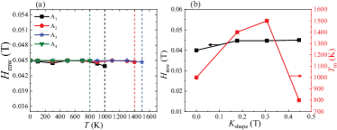
Lastly, we study how the minimally required of cosine CMP varies with temperature by keeping the optimal and at corresponding fixed. For or nm2, the variation of (black line) presented in the Figure 5(a) and it is found that the required remains almost constant up to a maximum temperature which is indicated by the vertical dashed line. After , the magnetization switching is not obtained. Similarly, for other or samples, we study the magnetization switching to find minimal of cosine CMP varies with temperature by keeping the optimal and at corresponding fixed and presented in Figure 5(a). It is noted that for higher and lower , the required are smaller. To be more explicit, the and the minimal at [] are plotted in Figure 5(b) which shows that thermal stability increases with up to a certain value and then decreases with the further increment of . It is because of a similar reason as the increment of the sample volume, rather than which is not dominant, increases the thermal stability. But for the larger , becomes dominant and it reduces the uniaxial anisotropy and thus the thermal stability decreases, i.e., decreases significantly. From the above study, we estimate the minimal , , and optimal at different for different or the cross-sectional areas. the minimal , and optimal at three different (= 0 K , 300 K and ) are summarized in the Table 1.
IV Discussions and Conclusions
The recent study [50] has demonstrated that the cosine CMP is capable of driving fast and energy-efficient magnetization switching of a nanoparticle with . However, this study investigates the cosine CMP-driven magnetization switching of the nanoparticle by including finite since the temperature is ubiquitous in nature. We found that cosine CMP-driven fast and energy-efficient switching is still valid in finite or even at room temperature, which is important in practice. For the lower volume of samples, the required minimal amplitude, the optimal , and minimal frequency decrease with temperature because of the decrement of magnetization with . We also find that with the increment of easy-plane shape-anisotropy, the required initial frequency of cosine CMP significantly reduces. For the larger volume of nanoparticles, the parameters of cosine CMP remains constant for a wide range of temperature which is useful practically. It is mentioned that there is a very recent study which demonstrates how to generate such cosine CMP in practice [70] and furthermore, several technologies [71, 72] are available to generate such cosine CMP. It is suggested to simulate magnetization switching for a real nanoparticle and thus obtain the optimal parameters; later these parameters can be employed for all the same nano-particles of the device. In addition, it is mentioned that this strategy might be applicable to switch the magnetization of synthetic antiferromagneticferrimagnetic nanoparticles. Therefore, the above findings may pave the way to realize the future-generation highly dense and speedy processing memory devices.
Acknowledgments
M T Islam acknowledges the National Key R&D Program of China (Grant No. 2021YFA1202200), the Khulna University Research Cell (Grant No. KU/RC-04/2000-158), Khulna, Bangladesh, and the Ministry of Education (BANBEIS, Grant No. SD2019972).
Appendix A Calculation of the rate of change of energy
The energy is a function of magnetization and microwave field, i.e., , . The rate of change of energy is then,
where, , the Hamilton’s equation of motion for the system is,
Now, after substituting the values of and in the equation, we get
We represent the second term of right-hand side of the above equation as . We can write it in the explicit form as the following. The rate of change of microwave field is
And, the magnetization is recast by
where and is the polar and azimuthal angle of the magnetization respectively.
Now, substituting the expression of and in the expression of , we get,
We can define , and then we get,
where defines the angular frequency .
References
- Sun et al. [2000] S. Sun, C. B. Murray, D. Weller, L. Folks, and A. Moser, Monodisperse FePt nanoparticles and ferromagnetic FePt nanocrystal superlattices, science 287, 1989 (2000).
- Woods et al. [2001] S. Woods, J. Kirtley, S. Sun, and R. Koch, Direct investigation of superparamagnetism in Co nanoparticle films, Physical review letters 87, 137205 (2001).
- Zitoun et al. [2002] D. Zitoun, M. Respaud, M.-C. Fromen, M. J. Casanove, P. Lecante, C. Amiens, and B. Chaudret, Magnetic enhancement in nanoscale CoRh particles, Physical review letters 89, 037203 (2002).
- Hillebrands and Ounadjela [2003] B. Hillebrands and K. Ounadjela, Spin dynamics in confined magnetic structures I & II, Vol. 83 (Springer Science & Business Media, 2003).
- Hubert and Schäfer [1998] A. Hubert and R. Schäfer, Magnetic domains: the analysis of magnetic microstructures (1998).
- Sun and Wang [2005] Z. Z. Sun and X. R. Wang, Fast magnetization switching of stoner particles: A nonlinear dynamics picture, Physical Review B 71, 174430 (2005).
- Slonczewski et al. [1996] J. C. Slonczewski et al., Current-driven excitation of magnetic multilayers, Journal of Magnetism and Magnetic Materials 159, L1 (1996).
- Berger [1996] L. Berger, Emission of spin waves by a magnetic multilayer traversed by a current, Physical Review B 54, 9353 (1996).
- Tsoi et al. [1998] M. Tsoi, A. Jansen, J. Bass, W.-C. Chiang, M. Seck, V. Tsoi, and P. Wyder, Excitation of a magnetic multilayer by an electric current, Physical Review Letters 80, 4281 (1998).
- Katine et al. [2000] J. A. Katine, F. J. Albert, R. A. Buhrman, E. B. Myers, and D. C. Ralph, Current-driven magnetization reversal and spin-wave excitations in Co Cu Co pillars, Phys. Rev. Lett. 84, 3149 (2000).
- Waintal et al. [2000] X. Waintal, E. B. Myers, P. W. Brouwer, and D. C. Ralph, Role of spin-dependent interface scattering in generating current-induced torques in magnetic multilayers, Phys. Rev. B 62, 12317 (2000).
- Sun [2000] J. Z. Sun, Spin-current interaction with a monodomain magnetic body: A model study, Physical Review B 62, 570 (2000).
- Sun [2003] J. Sun, Spintronics gets a magnetic flute, Nature 425, 359 (2003).
- Stiles and Zangwill [2002] M. D. Stiles and A. Zangwill, Anatomy of spin-transfer torque, Physical Review B 66, 014407 (2002).
- Bazaliy et al. [2004] Y. B. Bazaliy, B. Jones, and S.-C. Zhang, Current-induced magnetization switching in small domains of different anisotropies, Physical Review B 69, 094421 (2004).
- Koch et al. [2004] R. Koch, J. Katine, and J. Sun, Time-resolved reversal of spin-transfer switching in a nanomagnet, Physical review letters 92, 088302 (2004).
- Wetzels et al. [2006] W. Wetzels, G. E. Bauer, and O. N. Jouravlev, Efficient magnetization reversal with noisy currents, Physical review letters 96, 127203 (2006).
- Manchon and Zhang [2008] A. Manchon and S. Zhang, Theory of nonequilibrium intrinsic spin torque in a single nanomagnet, Physical Review B 78, 212405 (2008).
- Miron et al. [2010] I. M. Miron, G. Gaudin, S. Auffret, B. Rodmacq, A. Schuhl, S. Pizzini, J. Vogel, and P. Gambardella, Current-driven spin torque induced by the rashba effect in a ferromagnetic metal layer, Nature materials 9, 230 (2010).
- Miron et al. [2011] I. M. Miron, K. Garello, G. Gaudin, P.-J. Zermatten, M. V. Costache, S. Auffret, S. Bandiera, B. Rodmacq, A. Schuhl, and P. Gambardella, Perpendicular switching of a single ferromagnetic layer induced by in-plane current injection, Nature 476, 189 (2011).
- Liu et al. [2012] L. Liu, C.-F. Pai, Y. Li, H. Tseng, D. Ralph, and R. Buhrman, Spin-torque switching with the giant spin hall effect of tantalum, Science 336, 555 (2012).
- Zhang et al. [2018] Y. Zhang, H. Yuan, X. Wang, and X. Wang, Breaking the current density threshold in spin-orbit-torque magnetic random access memory, Physical Review B 97, 144416 (2018).
- Vlasov et al. [2022] S. M. Vlasov, G. J. Kwiatkowski, I. S. Lobanov, V. M. Uzdin, and P. F. Bessarab, Optimal protocol for spin-orbit torque switching of a perpendicular nanomagnet, Physical Review B 105, 134404 (2022).
- Aryal et al. [2022] M. Aryal, B. Choi, and T. Speliotis, Magnetic-field-free spin–orbit torque-driven magnetization dynamics in cofeb/-w-based nanoelements, AIP Advances 12, 015123 (2022).
- Wang et al. [2021] M. Wang, Z. Wang, C. Wang, and W. Zhao, Field-free deterministic magnetization switching induced by interlaced spin–orbit torques, ACS Applied Materials & Interfaces 13, 20763 (2021).
- Krizakova et al. [2022] V. Krizakova, M. Perumkunnil, S. Couet, P. Gambardella, and K. Garello, Spin-orbit torque switching of magnetic tunnel junctions for memory applications, Journal of Magnetism and Magnetic Materials 562, 169692 (2022).
- Ovalle et al. [2023] D. G. Ovalle, A. Pezo, and A. Manchon, Spin-orbit torque for eld-free switching in c_ 3v crystals, arXiv preprint arXiv:2301.01133 (2023).
- Grollier et al. [2003] J. Grollier, V. Cros, H. Jaffres, A. Hamzic, J.-M. George, G. Faini, J. B. Youssef, H. Le Gall, and A. Fert, Field dependence of magnetization reversal by spin transfer, Physical Review B 67, 174402 (2003).
- Morise and Nakamura [2005] H. Morise and S. Nakamura, Stable magnetization states under a spin-polarized current and a magnetic field, Physical Review B 71, 014439 (2005).
- Taniguchi and Imamura [2008] T. Taniguchi and H. Imamura, Critical current of spin-transfer-torque-driven magnetization dynamics in magnetic multilayers, Physical Review B 78, 224421 (2008).
- Suzuki et al. [2009] Y. Suzuki, A. A. Tulapurkar, and C. Chappert, Spin-injection phenomena and applications, in Nanomagnetism and Spintronics (Elsevier, 2009) pp. 93–153.
- Sun and Wang [2006a] Z. Z. Sun and X. R. Wang, Theoretical limit of the minimal magnetization switching field and the optimal field pulse for stoner particles, Physical review letters 97, 077205 (2006a).
- Wang and Sun [2007] X. R. Wang and Z. Z. Sun, Theoretical limit in the magnetization reversal of stoner particles, Physical review letters 98, 077201 (2007).
- Wang et al. [2008] X. R. Wang, P. Yan, J. Lu, and C. He, Euler equation of the optimal trajectory for the fastest magnetization reversal of nano-magnetic structures, EPL (Europhysics Letters) 84, 27008 (2008).
- Kim et al. [2014] Y. Kim, X. Fong, K.-W. Kwon, M.-C. Chen, and K. Roy, Multilevel spin-orbit torque mrams, IEEE Transactions on Electron Devices 62, 561 (2014).
- Bertotti et al. [2001] G. Bertotti, C. Serpico, and I. D. Mayergoyz, Nonlinear magnetization dynamics under circularly polarized field, Physical Review Letters 86, 724 (2001).
- Sun and Wang [2006b] Z. Sun and X. R. Wang, Strategy to reduce minimal magnetization switching field for stoner particles, Physical Review B 73, 092416 (2006b).
- Denisov et al. [2006] S. I. Denisov, T. V. Lyutyy, P. Hänggi, and K. N. Trohidou, Dynamical and thermal effects in nanoparticle systems driven by a rotating magnetic field, Physical Review B 74, 104406 (2006).
- Okamoto et al. [2008] S. Okamoto, N. Kikuchi, and O. Kitakami, Magnetization switching behavior with microwave assistance, Applied Physics Letters 93, 102506 (2008).
- Zhu and Wang [2010] J.-G. Zhu and Y. Wang, Microwave assisted magnetic recording utilizing perpendicular spin torque oscillator with switchable perpendicular electrodes, IEEE Transactions on Magnetics 46, 751 (2010).
- Thirion et al. [2003] C. Thirion, W. Wernsdorfer, and D. Mailly, Switching of magnetization by nonlinear resonance studied in single nanoparticles, Nature materials 2, 524 (2003).
- Rivkin and Ketterson [2006] K. Rivkin and J. B. Ketterson, Magnetization reversal in the anisotropy-dominated regime using time-dependent magnetic fields, Applied physics letters 89, 252507 (2006).
- Wang and Wu [2009] Z. Wang and M. Wu, Chirped-microwave assisted magnetization reversal, Journal of Applied Physics 105, 093903 (2009).
- Barros et al. [2011] N. Barros, M. Rassam, H. Jirari, and H. Kachkachi, Optimal switching of a nanomagnet assisted by microwaves, Physical Review B 83, 144418 (2011).
- Barros et al. [2013] N. Barros, H. Rassam, and H. Kachkachi, Microwave-assisted switching of a nanomagnet: Analytical determination of the optimal microwave field, Physical Review B 88, 014421 (2013).
- Tanaka et al. [2013] T. Tanaka, Y. Otsuka, Y. Furomoto, K. Matsuyama, and Y. Nozaki, Selective magnetization switching with microwave assistance for three-dimensional magnetic recording, Journal of Applied Physics 113, 143908 (2013).
- Klughertz et al. [2014] G. Klughertz, P.-A. Hervieux, and G. Manfredi, Autoresonant control of the magnetization switching in single-domain nanoparticles, Journal of Physics D: Applied Physics 47, 345004 (2014).
- Juthy et al. [2022] Z. Juthy, M. Pikul, M. Akanda, and M. Islam, Shape anisotropy effect on magnetization reversal induced by linear down chirp pulse, Physica B: Condensed Matter 630, 413671 (2022).
- Islam et al. [2018] M. T. Islam, X. Wang, Y. Zhang, and X. Wang, Subnanosecond magnetization reversal of a magnetic nanoparticle driven by a chirp microwave field pulse, Physical Review B 97, 224412 (2018).
- Islam et al. [2021a] M. T. Islam, M. A. S. Akanda, M. A. J. Pikul, and X. Wang, Fast magnetization reversal of a magnetic nanoparticle induced by cosine chirp microwave field pulse, Journal of Physics: Condensed Matter 34, 105802 (2021a).
- Dubowik [1996] J. Dubowik, Shape anisotropy of magnetic heterostructures, Physical Review B 54, 1088 (1996).
- Aharoni [1998a] A. Aharoni, Demagnetizing factors for rectangular ferromagnetic prisms, Journal of Applied Physics 83, 3432 (1998a).
- Gilbert [2004] T. L. Gilbert, A phenomenological theory of damping in ferromagnetic materials, IEEE transactions on magnetics 40, 3443 (2004).
- Fuller Brown Jr [1963] W. Fuller Brown Jr, Thermal fluctuations of a single-domain particle, Journal of Applied Physics 34, 1319 (1963).
- Hinzke et al. [2008] D. Hinzke, N. Kazantseva, U. Nowak, O. N. Mryasov, P. Asselin, and R. W. Chantrell, Domain wall properties of FePt: From bloch to linear walls, Phys. Rev. B 77, 094407 (2008).
- Lu and Wang [2009] J. Lu and X. R. Wang, Magnetization reversal of single domain permalloy nanowires, Journal of magnetism and magnetic materials 321, 2916 (2009).
- Hasegawa et al. [2017] T. Hasegawa, S. Kanatani, M. Kazaana, K. Takahashi, K. Kumagai, M. Hirao, and S. Ishio, Conversion of FeCo from soft to hard magnetic material by lattice engineering and nanopatterning, Scientific Reports 7, 13215 (2017).
- Dieny and Chshiev [2017] B. Dieny and M. Chshiev, Perpendicular magnetic anisotropy at transition metal/oxide interfaces and applications, Reviews of Modern Physics 89, 025008 (2017).
- Vansteenkiste et al. [2014] A. Vansteenkiste, J. Leliaert, M. Dvornik, M. Helsen, F. Garcia-Sanchez, and B. Van Waeyenberge, The design and verification of mumax3, AIP advances 4, 107133 (2014).
- Islam et al. [2019] M. T. Islam, X. S. Wang, and X. R. Wang, Thermal gradient driven domain wall dynamics, Journal of Physics: Condensed Matter 31, 455701 (2019).
- Islam et al. [2023] M. Islam, M. Akanda, F. Yesmin, M. Pikul, and J. Islam, Role of shape anisotropy on thermal gradient-driven domain wall dynamics in magnetic nanowires, Modern Physics Letters B 37, 2350013 (2023).
- Koch et al. [2000] R. H. Koch, G. Grinstein, G. Keefe, Y. Lu, P. Trouilloud, W. Gallagher, and S. Parkin, Thermally assisted magnetization reversal in submicron-sized magnetic thin films, Physical review letters 84, 5419 (2000).
- Li and Zhang [2004] Z. Li and S. Zhang, Thermally assisted magnetization reversal in the presence of a spin-transfer torque, Physical Review B 69, 134416 (2004).
- De Vries et al. [2017] J. De Vries, T. Bolhuis, and L. Abelmann, Temperature dependence of the energy barrier and switching field of sub-micron magnetic islands with perpendicular anisotropy, New journal of physics 19, 093019 (2017).
- Iwata-Harms et al. [2018] J. M. Iwata-Harms, G. Jan, H. Liu, S. Serrano-Guisan, J. Zhu, L. Thomas, R.-Y. Tong, V. Sundar, and P.-K. Wang, High-temperature thermal stability driven by magnetization dilution in CoFeB free layers for spin-transfer-torque magnetic random access memory, Scientific reports 8, 1 (2018).
- Liu et al. [2020] W. Liu, B. Cheng, S. Ren, W. Huang, J. Xie, G. Zhou, H. Qin, and J. Hu, Thermally assisted magnetization control and switching of and ferrimagnetic garnet by low density current, Journal of Magnetism and Magnetic Materials 507, 166804 (2020).
- Aharoni [1998b] A. Aharoni, Demagnetizing factors for rectangular ferromagnetic prisms, Journal of Applied Physics 83, 3432 (1998b).
- Kittel [2004] C. Kittel, Introduction to Solid State Physics, 8th ed. (Wiley, 2004).
- Islam et al. [2021b] M. Islam, M. Pikul, and X. Wang, Thermally assisted magnetization reversal of a magnetic nanoparticle driven by a down-chirp microwave field pulse, Journal of Magnetism and Magnetic Materials 537, 168174 (2021b).
- Sameh et al. [2023] M. Sameh, Y. Shukrinov, A. Y. Ellithi, T. El Sherbini, and M. Nashaat, Josephson current-assisted reversal of a single-domain nanoscale ferromagnet driven by cosine chirp pulse, Journal of Physics: Condensed Matter (2023).
- Cai et al. [2013] L. Cai, D. A. Garanin, and E. M. Chudnovsky, Reversal of magnetization of a single-domain magnetic particle by the ac field of time-dependent frequency, Physical Review B 87, 024418 (2013).
- Cai and Chudnovsky [2010] L. Cai and E. M. Chudnovsky, Interaction of a nanomagnet with a weak superconducting link, Physical Review B 82, 104429 (2010).