Seeing the Unseen: The REVEAL protocol to expose the wireless Man-in-the-Middle
Abstract
A Man-in-the-Middle (MiM) can collect over-the-air packets whether from a mobile or a base station, process them, possibly modify them, and forward them to the intended receiver. This paper exhibits the REVEAL protocol that can detect a MiM, whether it has half duplex capability, full duplex capability, or double full duplex capability. Protocol is based on synchronizing clocks between the mobile and the base station, with the MiM being detected if it interferes in the synchronization process. Once synchronized, the REVEAL protocol creates a sequence of challenge packets where the transmission times of the packets, their durations, and their frequencies, are chosen to create conflicts at the MiM, and make it impossible for the MiM to function. We implement the REVEAL protocol for detecting a MiM in 4G technology. We instantiate a MiM between the 4G/5G base station and a mobile, and exhibit the successful detection mechanisms. With the shared source code, our work can be reproduced using open software defined cellular networks with off-the-shelf devices.
I Introduction
A Man-in-the-Middle (MiM) collects over-the-air radio samples, whether transmitted by a mobile or the base station, processes the message, possibly modifies the contents of the packet 111In this work, we assume the MiM cannot decode encrypted traffic., and forwards the packet. The two endpoints of the thus created link may be oblivious to the presence of the MiM. The challenge addressed in this paper is how to detect the presence of a MiM that wants to stay hidden.
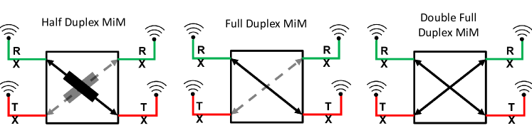
The MiM can have one of three packet forwarding capabilities - Half duplex, Full duplex or Double full-duplex, as shown in Fig. 1. A half duplex node cannot transmit while listening, a full duplex node can forward messages while listening but only in one direction, and a double full duplex node can simultaneously listen and forward messages in both directions. The attack vector that is chosen decides how the MiM processes the message.
We present a protocol, REVEAL, that can detect a MiM that has any one of the above three forwarding capabilities. This protocol is based on the initial theoretical work in [1] for Half duplex and Full duplex MiMs. The REVEAL protocol is designed to function so that it is agnostic to the attack vector. We experimentally evaluate the REVEAL protocol. We also show the efficacy of the solution and relevance for the current day 4G/5G cellular wireless technology.
The entire process of creating an attack vector adds finite delay to the wireless traffic. Consider a simple MiM-Relay. The relay either immediately re-transmits the incoming signal, or demodulates and re-modulates the packet before forwarding the received packet. The works [2, 3] show that even a simple MiM acting like a relay that processes the message only at the radio layer delays the traffic. A more sophisticated MiM may perform several data processing tasks. [4, 5]. The MiM attack [5] that claims to break 4G communication networks processes data traffic all the way up to the data link layer, the top most layer of the 4G/5G protocol stack. Also, after processing the packet at the desired layer in the protocol state, the MiM reconstructs the over-the-air packet, all the way down to the physical layer. This entails a delay before the packet is relaunched into the wireless medium.
In a communication network, wired or wireless, all nodes must maintain a common time despite having independent time source - clocks. Clock synchronization is necessary to establish a common time in a communication network. For example, a base station and a mobile must have a common time to schedule communication opportunities.
Any communication technology wired or wireless has an associated clock synchronization mechanism. In particular for Cellular networks, where the location of a mobile changes as user moves, a significant portion of protocol design is dedicated for clock synchronization [6, 7].
A natural question one can ask is: Can we devise mechanisms taking advantage of clock synchronization to detect a MiM? This question was first examined in [1], where the cases of half duplex and full duplex MiMs were investigated. In this paper, we examine the detection mechanisms for all the three types of MiM nodes. We show how to detect double full duplex MiMs, and present experimental results for all three scenarios. We show that the entire end-to-end scheme including clock synchronization can be realized over software defined radios, and present the performance results. To demonstrate them in action, we built MiM nodes using software defined radios. Using our software-defined radio MiM we launch attacks on the 4G and 5G network. We show that the mobile naively connects to the Cellular network totally ignorant of the MiM. Then we use our mechanism to catch the MiM nodes. Therefore it is indeed possible to detect middle nodes, irrespective of the signature of the attack or attack vector of MiMs. The design and source code of the software defined MiM is available at [8].
Summary of contributions in the work:
-
•
On the basis of the thorough theoretical work in [9], to the best of our knowledge, this work is first practical implementation of MiM detection methods
-
•
One of the challenges we addressed to detect MiM is to show the feasibility of MiM attack on Cellular Network; We built half, full and double full duplex MiM nodes
-
•
With our implementation, we show a live MiM attack on 4G network: both full duplex MiM attack and double full duplex MiM attack
-
•
We devised usable protocol that detects presence of a MiM
-
•
Finally, we demonstrate the working of our protocol
The rest of the paper is organized as follows. In Section III, we explain how to synchronize two clocks, and present how a MiM node impacts the clock synchronization. We present our detection mechanisms in Section V. The MiM node implementation details, and attack and detection on a 4G/5G network are in Section VI.
II Related Work
We first review several MiM attack vectors that target commonly employed wireless technologies. Elaborating on how a MiM forwards the messages in the link, we present several proposals in literature to detect the MiM.
The key differentiating factor of our REVEAL protocol is that it catches any middle node, whether it is half, full or double full duplex. To the best of our knowledge REVEAL is the only work that condenses the detection mechanisms into three fundamental principles that do not require any additional information on the attack vector, technology or fingerprints whatsoever. Therefore REVEAL can detect any future MiM attacks as communication protocols and technology continue to progress.
IEEE 802.11 Family
Hwang et al. [10] have shown how to attack 802.11a/b/g networks using a rogue access point capitalizing on the security vulnerabilities of the authentication framework. Lynn and Baird have presented a ”Monkey Jack” attack that inserts a MiM between an 802.11b station and an access point [11]. The attacker listens to the channel of the access point, but forwards on a different channel. Ignorant of this fact, the wifi station connects to the attacker. To mitigate such attacks, the authors have proposed strong authentication and radio signal shaping such that the wireless nodes transmit in a directional fashion and with low power. Serious flaws in the Wired Equivalent Privacy of 802.11b make it possible for a MiM to even modify the contents of the packets ][12]. To mitigate this, improved encryption mechanisms have been proposed, but the superseding encryption mechanisms of Wifi Protected Access (WPA) and WPA-2 are also found to be vulnerable [13]. Works [14, 15, 16] detail the MiM attacks. Kumar et al. [17] have proposed modifications to the vulnerable protocol to mitigate the attack. Recently, Steinmetzer et al. [18] has devised a way to launch an MiM attack on a 802.11ad mm-wave network, and observed that anomalies in received signal strength and modifying beacon configurations help detection.
At the radio level, all the attacks need either a half or full duplex MiM.
Our full duplex detection method detects the presence of all such MiMs.
Given the constant discovery of new exploits across the generations of wireless standards, our attack agnostic method serves as a useful tool to detect MiMs.
Cellular Technology
2G Technology
Strobel [19] has discussed an attack on a 2G network where the attacking device is a half duplex MiM that alternately impersonates the base station and the mobile, and taps the communication link.
3G Technology
The authors of [20] have found a vulnerability to downgrade a mobile connected to a 3G network to 2G, after which a MiM attack on 2G is launched. Due to the lack of message integrity check, the MiM eavesdrops on the mobile’s communication with the 2G base station. Beekman et al. discovered an attack vector that exploits weak authentication to launch an MiM attack that can modify the routes and contents of T-Mobile’s WiFi calling service [21]. Improved verification brought closure to the attack.
4G/5G Technology
The authors of [22, 23, 5] found missing integrity checks in some network configurations of 4G and early 5G protocols, and demonstrated the feasibility of a MiM. In these attacks, the MiM relays modified information between the mobile and the base station. Proposals to prevent the attacks include better network configurations and changes to protocol standards to close the integrity gaps.
Our experimental section describes a MiM attack on a 4G network where all the over-the-air packets go through the MiM, but our MiM does not modify the contents of messages. We have also used the same open software and hardware described in the works [4, 23] to show our detection mechanisms. While the authors of the above have focused on mechanisms to prevent the MiM attacks, our work can detect the MiM while the attack is happening. The goal of the REVEAL protocol is to detect MiM attacks irrespective of attack vector and wireless technology.
The MiM attack in SigUnder [24] only modifies the un-encrypted broadcast messages of the 5G protocol. Since the MiM needs to first receive the broadcast messages before sending the modified contents, this half-duplex MiM can be caught by our detection methods. Taking advantage of weak authentication and lack of integrity in certain configurations of the 4G protocol, IMP4GT [25] MiM modifies the small sized uplink and downlink packets. The IMP4GT attack inserts a half-duplex relay between the base station and the mobile. The REVEAL protocol can detect all of the above mentioned attacks as they use either half or full-duplex MiM devices.
Technology Agnosticism
Fingerprinting methods have become popular for MiM detection in the literature. Kim et al. [26] have capitalized on variations in received signal strength before and after a MiM attack. However, the MiM can counter such detection mechanisms by adjusting its transmit power. Detection methods based on observing patterns in TCP-ACK pairs [27], inter-packet arrival times [28], round trip times [29, 30], and traffic [31], have also been proposed. However, radio propagation conditions can affect inter-packet arrival times, round trip times require accurate knowledge of the distance between the mobile and the base station, and user traffic affects TCP-ACK pairs. We intend for the REVEAL protocol to be a useful tool for detecting MiMs regardless of the attack vector or communication protocol employed.
Building on the work [1], we present the REVEAL protocol and demonstrate how REVEAL exposes half, full and double full duplex MiMs in a 4G network. The method also works for WiFi and sub-6GHz 5G.
III Background
III-A Clock Synchronization
Communicating devices share the medium and must schedule message exchanges to operate in harmony. For networked devices that share the wireless medium and use cellular technology for packet exchanges, the base station schedules both uplink and downlink traffic for the mobiles. To follow the schedules precisely the base station and mobiles must have the same time.
Suppose the base station schedules a conversation from time to . Then the mobile must use that opportunity to precisely initiate communication at and cease at . In 4G/5G network terminology, the base station grants the communicating opportunity, i.e., a time slot in a particular frame and using symbols to . If a mobile’s timing is off, the window of operation can overlap with that of other devices, resulting in packet collisions which degrade network throughput.
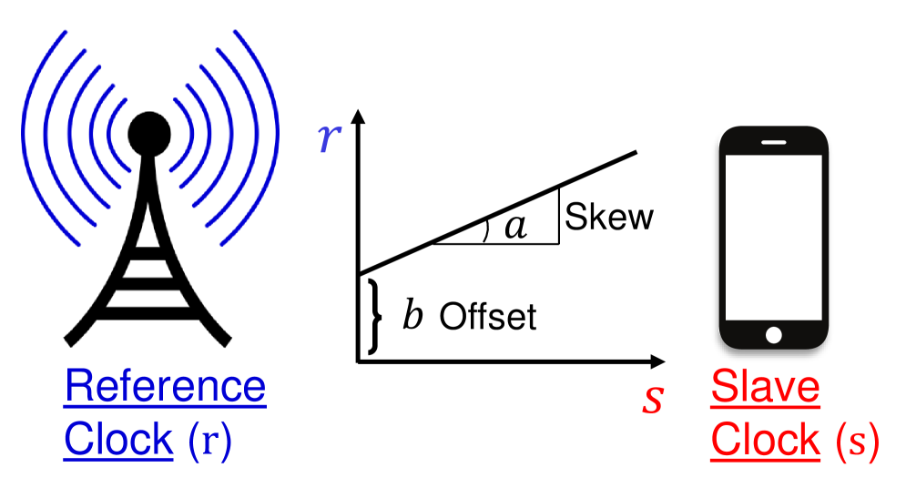
Indeed, the primary requirement put on the mobile to connect to scheduled communication technologies like cellular networks and to remain connected is to maintain time synchronized to that of the base station. As the time must be same for the entirety of the network, each mobile synchronizes its clock to the base station’s clock. Consider a base station that has a reference clock as shown in Fig. 3, with the mobile’s clock slave to that of the base station. The IEEE 802.11 family of technologies [32], the cellular technologies 4G and 5G [7], and the short range communication technology of Bluetooth [33], all have distinct protocols to achieve clock synchronization. For ease of exposition, we present below only the fundamental idea behind synchronization. The documents [6, 34] describe clock synchronization procedures in 4G and 5G.
Suppose and represent the clock-based time stamps from the reference and slave clocks respectively. If gives the relationship between the two clocks, then is the skew and is the offset of the slave. The skew gives information on the rate of change of the slave clock with respect to the rate of change of the reference clock. Ideally, skew is 1. The ambient temperature, humidity, pressure, vibrations, etc., affect the crystals in the clocks, and therefore the mobile needs to perform skew and offset estimation persistently [35].
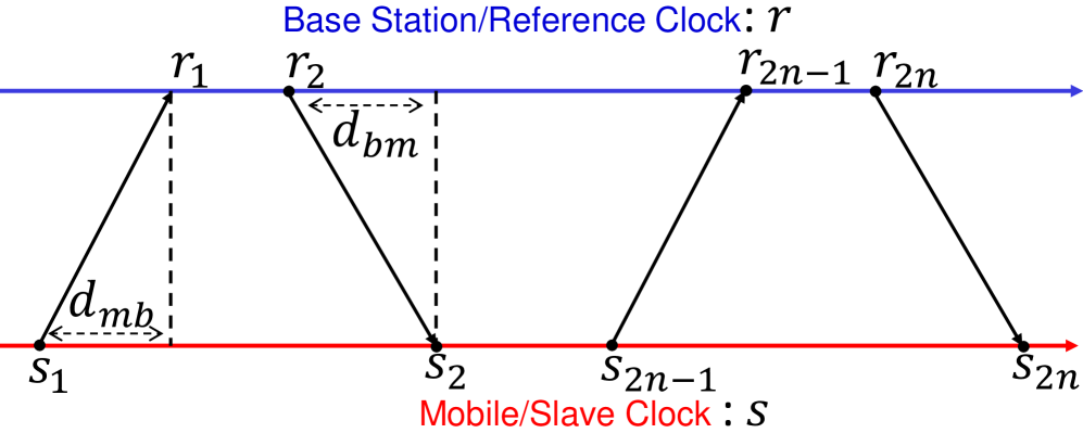
To estimate skew and offset 222The over-the-air clock synchronization mechanism is different in 4G/5G networks; however the core network follows a similar mechanism., the base station and the mobile exchange packets that carry time stamps from their respective clock sources, i.e., the snapshot of the time just before sending a packet, and the snapshot of the time just after receiving a packet, both according to their local clocks.
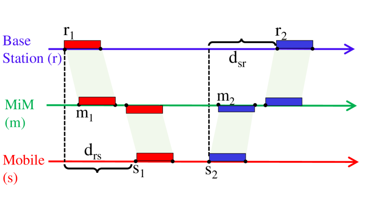
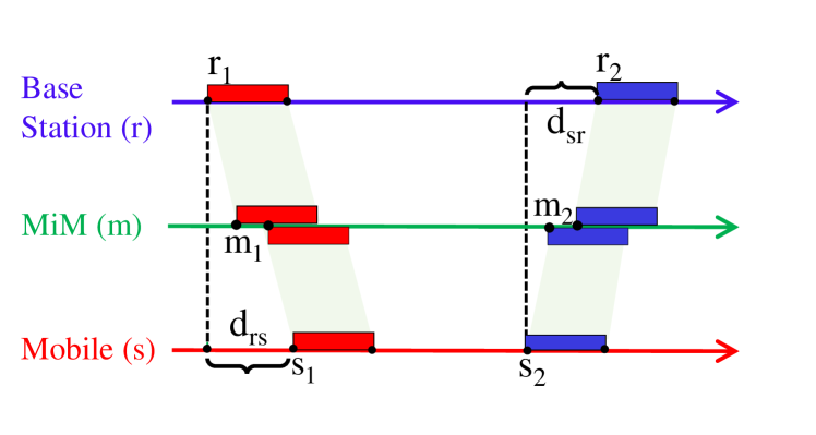
Let denote the time stamp of a packet at the mobile, according to the mobile’s clock, at the time it is sent, and let denote the time stamp at the base station when it is received, according to the base station’s clock. For a packet travelling in the reverse direction, let denote the time stamp of a packet at the base station at the time it is sent, according to the base station’s clock, and let denote the time stamp at the mobile when it is received at the mobile, according to the mobile’s clock. Suppose and are uni-directional delays from the mobile to the base station and vice versa, measured according to the reference clock, which in this case we suppose to be that of the base station. Then and . To synchronize the clocks we need to estimate offset , skew , and also the path delays , . Suppose (for simplicity of notation) that even numbered packets are sent from the base station to the mobile, while odd numbered packets are sent in the reverse direction, as shown in Fig. 3. Then
| (1) |
This matrix is of rank 3 only, since the last column is the difference between the second and third columns. Hence, as pointed out in [36], in general it is impossible to estimate all four parameters . Thus clocks cannot be synchronized if the delays in the uplink and downlink directions are asymmetric. Consider, for example, a mobile for which skew = 1. If a packet transmitted at mobile time 100s is received at base station time 100.000001s, then it is impossible to distinguish whether delay and , or and .
On the positive side, the skew can be estimated by
| (2) |
Moreover, for any packet transmitted by the mobile/base station, the mobile/base station can estimate the time at which it is received by the base station/mobile according to the base station’s/mobile’s clock [36]. To see this, note that from (1), . Since all the quantities on the RHS are known or estimable, the quantity can be determined based on time-stamped packet exchanges. Hence for any future packet transmitted by the base station at local time , its receipt time at the mobile, can be determined by the base station. That is, knowing , the base station can determine . Likewise, knowing , the mobile can determine . This capability is used by REVEAL.
In the special case where the delays in the two directions are known to be equal, i.e., , the delays as well as offset can be estimated. The protocol Precision Time Protocol [37] determines from technological considerations the amount by which the delays in the two directions are asymmetric. Subsequent to this, the remaining delays are symmetric in the two directions and can thus be estimated.
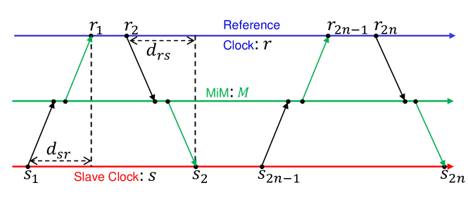
When there is a MiM between the mobile and the base station, it can only delay the packets [1] from mobile to base station by a constant, say ; else, if it delays different packets from mobile to base station by different times, then the inconsistent behavior can be detected. Likewise, the MiM can only delay packets from the base station to the mobile by a constant, say .
A MiM interfering in any other way with the clock synchronization process itself, besides adding a constant delay in each direction, can thereby be detected. Based on this approach we synchronize the clocks of the mobile and base station. We have conducted an experimental investigation and report on the estimation results in Section VI.
IV Capabilities of A MiM
As noted above, we can broadly classify an MiM node into three types based on its forwarding capability: Half-duplex , Full-duplex or Double Full-duplex. Fig. 1 summarizes the forwarding capabilities a MiM might use to attack a communication link.
Half-duplex MiM The half-duplex only capable MiM must first choose the direction of attack: uplink or downlink. Then, since simultaneous listening and forwarding is not possible for a half-duplex MiM, it must listen to the entire packet before forwarding. Hence, packets passing through a half-duplex node are delayed at least by the length of the packet. There may be an additional processing delay on top of this. This is shown in Fig. 5.
Full-duplex MiM As in the case of the half-duplex case, a full duplex MiM must first choose the direction of attack: uplink or downlink. The concurrent reception and transmission of packets by a full duplex MiM enables it to forward packets in the chosen direction quicker than its half-duplex counterpart, as illustrated in Fig. 6. However, a limitation of a full duplex MiM is its inability to manage simultaneous bidirectional traffic between the base station and the mobile. It can either forward packets from mobile to base station or base station to mobile, but not both at the same time.
Double full-duplex MiM A double full duplex MiM is capable of listening to and forwarding traffic simultaneously in both directions, making it the ideal choice for orchestrating an attack vector and taking over the communication link between the base station and the mobile.
V Detection of MiM
The REVEAL protocol is designed to detect the presence of a MiM node, regardless of its forwarding capability
V-A Half-duplex MiM
The half-duplex MiM must receive the complete packet before it can forward; therefore the delay is at least the duration of the packet itself. The transmission of messages through a half-duplex MiM therefor results in significant delays, exceeding those caused by path delay, which is determined by the distance between the base station and the mobile. The additional delay is proportional to the length of the message, as shown in Fig. 7. Hence long packets traversing through a half-duplex MiM experience much higher delays.
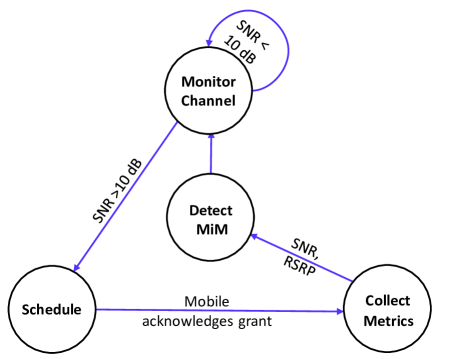
Detecting a half-duplex MiM can be achieved by sending a sufficiently long packet. Fig. 9 presents the state machine of REVEAL protocol to expose a half duplex MiM. The protocol instructs the base station to schedule a very long packet for the mobile. The MiM is forced to add an additional delay at least equal to the increase in the length of the packet. The REVEAL protocol capitalizes on this fact to detect the presence of a half-duplex MiM, as described below.
The base station monitors the channel conditions in its “Monitor channel” state in the state machine of the protocol in Fig. 9. In a 4G/5G network, when the link signal to noise ratio (SNR) is 10 dB and above, up to 64 QAM modulated symbols pass through the wireless link with high probability [38, 39] 333Also, experimentally we found detection tests have very accuracy at SNR above 10 dB, further reference in Section VI. The base station continues to monitor the SNR and moves to the “Schedule” state when SNR 10 dB. In this state, the base station gives a long communication opportunity to the mobile either in downlink or uplink. The minimum scheduling opportunity in a 4G cellular network, transmission time interval (TTI), is 1 millisecond. To schedule longer opportunities, the base station allocates continuous communication opportunities. After receiving confirmation from the mobile that it is aware of the granted opportunity, the base station moves to the “Collect metrics” state. In this state, the base station records the SNR and received power. The half-duplex MiM is unaware when the data transmission will end, and continuously listens before forwarding.
Meanwhile, while waiting for the data from the MiM in the scheduled opportunity, the receiver experiences a silent period as the messages are delayed beyond the scheduled time. In this silent period, received power and SNR are poor.
The base station collects the metrics, SNR and received power, and moves to the “Detect MiM” state, where it decides whether a MiM is present.
V-B Full-duplex MiM
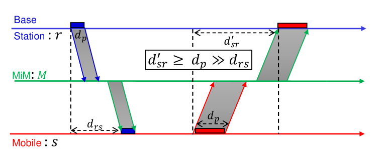
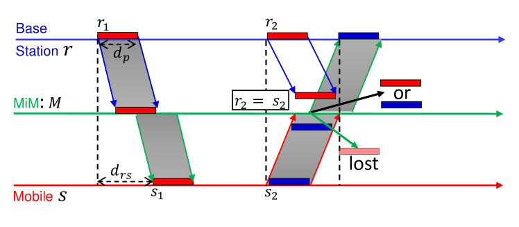
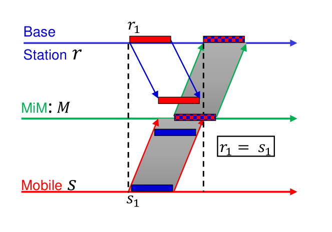
A full-duplex MiM can forward incoming packets as soon as they arrive, but can do so only in one direction at a time. Consider a downlink packet that is processed by the MiM and transmitted towards the mobile, as shown in Fig. 8. The base station and mobile coordinate to transmit two packets, one transmitted by the base station at time , and one transmitted by the mobile at time . These packets are timed so that they impinge on the MiM at the same time. Hence the MiM cannnot simultaneously forward both, and is forced to abandon packets in one of the directions. By checking if they have received each other’s packets, the base station and mobile can detect the failure of the MiM to forward both packets.
Achieving this coordination depends critically on the results of the Clock Synchronization algorithm. As shown in Section III-A, a mobile interfering in any way other than adding a constant delay to packets in a direction, can be detected. which is performed with the MiM acting as go between. As noted in Section III-A, an outcome of the clock synchronization process is that the mobile can time its packet transmission so that the MiM-relayed packet is received at a specified time by the base station according to the base station’s clock. Similarly, the base station can time its packet transmission so that the MiM-relayed packet is received at a specified time by the mobile according to the mobile’s clock. Using this capability as well as the choice of the length of the packets the base station and mobile can ensure that a conflict is created at the MiM. Therefore, this precisely timed bi-directional data traffic test exposes the presence of a Full-duplex MiM.
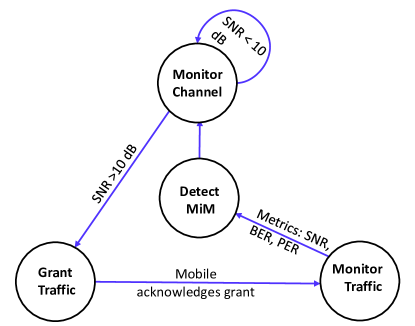
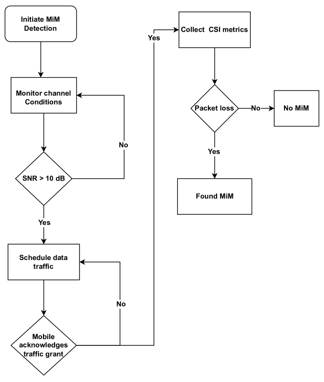
The state machine for the REVEAL protocol which is used to detect a full-duplex MiM is depicted in Figure 10. As described in Section V-A, there is an initial period of monitoring. After this, the base station proceeds to the ”Grant traffic” state, where it schedules uplink and downlink traffic simultaneously. Once the mobile acknowledges the receipt of these grants, the base station moves to the ”Monitor traffic” state to monitor the metrics of SNR, bit error rate (BER), and packet error rate (PER). These metrics indicate whether the packets reach their intended destination. After collecting the metrics, the base station enters the ”Detect MiM” state, where it determines whether a MiM is present. If a MiM is detected, the base station moves back to the ”Monitor channel” state to observe the channel conditions again.
The flow chart describing the detection protocol is shown in Fig. 11
V-C Double full-duplex MiM
A double full-duplex MiM forwards traffic in both directions and can do so with little to no delay. The time-driven conflicts that the REVEAL protocol uses to expose half and full duplex MiMs cannot detect a double full-duplex MiM. However, wireless technologies that are capable of operating on multiple frequency bands can still detect the presence of a double full duplex MiM.
Cellular technologies like 4G and 5G operate in frequency division duplex mode 444Our work can be extended to time division mode of cellular networks, but for the clarity of presentation in this work we focus only on frequency division duplex mode , and both the base station and the mobile are designed to operate on several bands for interoperability and seamless operation across the globe.
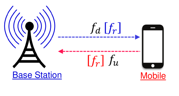
As depicted in Fig 12, a frequency division duplex (FDD) base station uses frequency to communicate with the mobile, and the mobile uses a frequency to talk to the base station. A double full-duplex MiM listens and forwards transmissions of both and . To attack the FDD link, the MiM needs knowledge of the operating band. The MiM can scan the spectrum to detect transmissions in and . After narrowing down on the frequencies, the double full-duplex MiM launches the attack.
The REVEAL protocol takes advantage of the need for the double full duplex MiM to perform spectrum sensing in order to launch the attack. The base station can instruct a mobile via an encrypted control message asking it to change its frequency of operation in either downlink or uplink frequency to . Unaware of this change, the double full-duplex MiM still listens and forwards data on prior sensed frequencies. Consequently all the packets that are communicated on link are lost. One choice of could be such that or , where BW is the sensing bandwidth of the MiM. The ideal choice of BW is in the order of GHz. 555Commercial 4G/5G cellular modems have operating bandwidth anywhere from 20 to 400 MHz. A large BW forces the double full duplex MiM to have additional capability of wider operating bandwidth . Spectrum sensing takes a longer duration if .
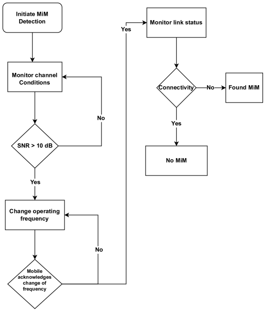
To detect a double full duplex MiM, REVEAL follows the sequence of steps in Fig. 13. As and when the base station decides to perform a frequency change test, and SNR conditions are good. The base station informs the mobile to change either uplink or downlink frequencies, or both. Once the base station receives acknowledgement from the mobile indicating the receipt of the message, protocol monitors link state and observes the radio conditions on the new frequencies.
The base station detects the MiM by a failure to receive the packets sent by the mobile on the new frequencies, as the transmissions must go via the double full duplex MiM to reach the base station. The SNR and received power indicate whether there is an on ongoing transmission. If the mobile’s connection status, the base station decides whether a double full duplex MiM is present or not.
V-D REVEAL Protocol
The goal of the REVEAL protocol is to detect a man-in-the-middle, whether it is half, full, or double full duplex capable. Therefore, the protocol should independently move to MiM detection mechanisms. The REVEAL protocol schedules detection methods with the scheduling policy left open. The system designer can follow the scheduling policy of his/her choice, following which the REVEAL protocol moves to any of the state machines presented in Figs. 9, 10, and 13. There is no particular policy that has an advantage over another as a MiM attack can happen at any point in time.
VI Implementation
VI-A 4G Network
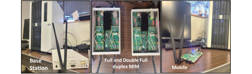
We use srsRAN 4G network source code [40], a public software project that has 4G base station (eNodeB), mobile (user equipment, UE) and network core. Using srsRAN, a host machine with USRP X310 [41] as base station and another host machine with USRP B210 [42], we create a local 4G network and show attack and defence mechanisms.
On machine 1, we launch network core and eNodeB softwares. Machine 1 connects to a USRP X310. eNodB software interfaces with USRP X310 and acts as base station. Similarly, on machine 2, we run UE software that interfaces with USRP B210. This combination makes a 4G mobile. The mobile, once connected to the 4G network successfully, gets an IP address assigned. Any application on machine 2 can then communicate with machine 1 via 4G network.
We ensure there is no external interference on the wireless channel. To do so, we operate both uplink (2400 MHz) and downlink (2500 MHz) on frequencies far away from local wireless transmissions. When connected directly to the base station in the absence of MiM, at the mobile side, we observe pathloss of 64 dB, reference signal received power of -64 dBm, timing advance (a metric that the 4G protocol uses to adjust the timing offset between the base station and the mobile) to be 0.5 S, SNR as high as 20 dB, and Modulation and Coding Scheme index (a parameter that indicates channel conditions for data scheduling 666Higher the better, maximum usable index 28.) of 28, during a bi-directional traffic session. We observe no packet losses either in uplink or downlink. The locations of the mobile, the base station, and the MiM remain the same throughout the experiments. Using the clock synchronization method in Section III and assuming bi-directional delays are same, through 2, we found that the skew between the base station and the mobile clock is 0.9935607.
VI-B Full Duplex MiM
The full duplex man-in-the-middle (MiM) possesses the capability to simultaneously intercept incoming over-the-air traffic and forward it to its intended destination. It is widely acknowledged within the academic community that constructing wireless transceivers capable of both transmitting and receiving on the same channel, known as full duplex transceivers, represents a significant technical challenge due to the complexity of their required radio hardware architectures [43]. The successful operation of such a full duplex transceiver is contingent upon the use of both digital and analog signal cancellation to achieve over 100 dB isolation between the transmitter and receiver.
Upon conducting a thorough investigation of the cellular standards [7], we have ascertained that there is no explicit verification mechanism for carrier frequencies. Operators of cellular networks are mandated to comply with the guidelines stipulated by local regulatory authorities pertaining to the utilization of radio frequencies. Consequently, cellular protocols have been designed to allow the base station and mobile to communicate across various frequency bands. Additionally, the initial step for mobile communication is the detection of a cellular base station irrespective of the network operator, following which a connection request is initiated with a ”visible base station”. Subsequently, access to the network is granted after successful validation of access credentials.
Such a design choice in cellular standards greatly simplifies the hardware architecture of a full duplex MiM. By allowing the base station and the mobile to communicate on a multitude of frequency bands, the full duplex middle node can listen to the base station’s downlink traffic on frequency and forward it on a different frequency . As a result, the mobile can discover the base station on instead of .
VI-B1 Full duplex MiM prototype
We used an additional USRP X310 to build the equivalent of a full duplex MiM. The X310 radio has two independent radio chains and can simultaneously receive and transmit. We configure one of the radio chains to receive the base station transmissions and another chain to re-transmit the received sample. We do not modify the received samples. In our experiment, as we are aware of our 4G/5G base station’s operating frequencies, we directly configured the MiM to receive on that frequency. With any open-source radio software like GNU-Radio, it is also straightforward to develop a spectrum analyzer, or using public databases [44] it is fairly easy to identify the operating frequencies of a target base station.
A full-duplex MiM need not listen to the entire transmission before forwarding. It can choose the forwarding delay to be be as small as possible. The receive chain of X310 has a digital down-converter to collect the base-band samples. These samples are then sent to the digital up-converter of the transmit chain of X310. We configure the X310’s receive chain to stream packets of base-band samples to the transmit chain. The time to down-convert the over-the-air signal, length of the streaming packet and the time to up-convert to a different frequency comprise the total additional delay our MiM adds to the link. To reduce transit time of samples through our MiM, the only controllable parameter in X310 is the size of the streaming packet. We configure the samples per packet to its least possible value; each packet carries 24 of 32bit base-band samples from receive chain to transmit chain. The source files of the MiM are available at [8].
VI-B2 Full duplex MiM attack
Since we have access to the configuration files of the base station and the mobile, we can operate the 4G network on frequencies in ISM band and with operating bandwidth of 10 MHz. Also, our configuration ensures there is no direct link between the base station and the mobile. The 4G base station and the mobile operate in frequency division duplex mode, i.e., they use different radio frequencies for uplink = 2400 MHz and downlink = 2500 MHz. Our goal is to create a full duplex MiM and show that the mobile connects to the 4G network via MiM, but not directly to eNodeB. Our 4G MiM listens to = 2400 MHz and transmits the incoming packets without changing the contents on = 2500 MHz. On machine 2, we configure the mobile to listen downlink on = 2500 MHz, and transmit uplink on = 2400 MHz. Because of this configuration, the UE cannot directly listen to eNodeB. All the communication to the UE must go via the MiM and not directly from eNodeB as the base station’s, and mobile’ operating frequencies are configured to listen to our MiM.
As shown in Fig. 14, we keep eNodeB and UE 2mt apart and keep MiM in between them. Our first observation is that the mobile naively connects to the network and gets an IP address from the network. This proves that our full-duplex MiM is operational. The SNR at UE is 18 dB, and pathloss is 64 dB. Since the communication is via MiM, communication is delayed. eNodeB indicates to the UE that the timing adjustment value is 5.2, whereas it is 0.5 when UE is directly connected. As the UE can be located anywhere in the coverage area of eNodeB, only an Oracle can locate the UE; therefore the timing adjustment value does not help in detecting the MiM. The clock skew between the eNodeB and UE in the presence of full-duplex MiM is 1.002443.
VI-B3 Detection
To detect the MiM, it is sufficient to initiate bi-directional traffic between the base station and the mobile. Fig 15 shows the mechanics of the detection. The 4G MiM is forced to make a choice, either to forward uplink traffic or to forward downlink. The packet in one of the two directions that is dropped at the 4G MiM cannot reach its destination, exposing the presence of the MiM. Since a 4G network operates in frequency division duplex mode, the 4G MiM forwards traffic on uplink frequency or downlink frequency.
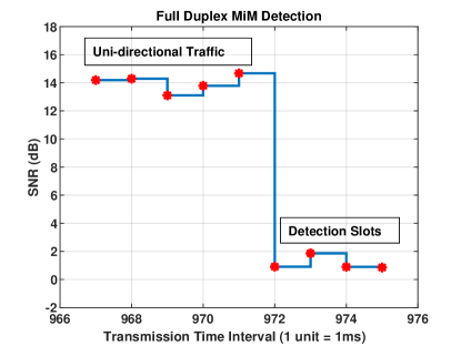
Frequency configuration in our network is slightly different from the standard configuration as we configure the uplink transmit frequency of UE to be the same as the downlink transmit frequency of eNodeB, which usually are different. This network configuration allows all the uni-directional traffic to reach its destination. However, when the eNodeB and UE transmit at the same time, the packets naturally collide at the MiM. Instead of looking for a lost packet during the MiM detection test, we can observe the SNR of the link to detect the presence of the MiM since the SNR at both the mobile and the base station drops due to the collision, ideally to 0 dB.
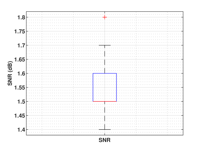
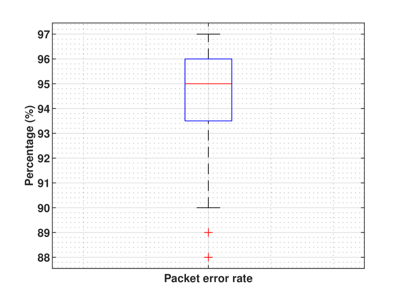
In one of the detection trials, the SNR in the downlink was 14 dB at the mobile side from transmission time units 996 to 971. During this time, packets were only sent in the downlink from the eNodeB to the UE. From transmission time unit 972 until 975, bi-directional traffic was initiated, with packets being sent in both directions. Bi-directional packets from 971 to 975 arrived at the 4G MiM at the same time and on the same frequency, and the MiM was unable to separate these packets. As a result, the eNodeB and UE received collided packets. Since two packets of the same energy collided, the SNR of the packet is ideally 0. However, in our case, we observed an approximate SNR of 1 dB. We repeated this detection experiment 50 times, and the box plot of SNR at the time of detection is shown in Figure 17(a), with a median SNR of 1.5 dB. Additionally, Figure 17(b) shows that the median packet error rate over the trials is 95%.
VI-C Double Full Duplex MiM
A double full duplex MiM forwards the traffic in both directions. We reuse the design of the 4G MiM described in Section VI-B2. A full duplex MiM only forwards traffic in one direction, but a double full duplex MiM forwards traffic in both directions. So, we use two USRP X310s in conjunction to build a double full duplex MiM.
We operate the 10 MHz bandwidth 4G base station on frequencies in ISM band, downlink, = 2400 MHz and uplink = 2500 MHz. The mobile listens on = 2440 MHz and transmits on = 2480 MHz. The double full duplex MiM listens on = 2400 MHz and forwards downlink traffic on =2440 MHz. To forward uplink traffic, double full duplex MiM listens on =2480 MHz and forwards on = 2500 MHz.
Again, the network configuration ensures that the mobile can listen to the base station’s traffic only via the MiM. Similar to the full duplex MiM experiment, the mobile connects to the network and receives an IP address. The host machine 2, where the mobile source code is running, receives and sends data traffic to host machine 1 via the 4G wireless link. The clock skew between the base station and mobile in this experiment is found to be 1.003142.
VI-C1 Detection
To detect a double full duplex MiM node, the REVEAL protocol requires the base station to change its frequency of operation. In a 4G network, changing the operating frequency can be achieved by requesting the UE to perform a handover to a new eNodeB. Handover involves changing the mobile device’s connection to a neighboring base station that operates on a different carrier frequency. When the mobile device receives the hard handover trigger, it searches for the new base station. We assume that the double full duplex MiM cannot decode the encrypted messages sent from the base station that request the mobile device to perform a handover. As the MiM is unaware of the handover trigger, it continues to listen to the previous base station.
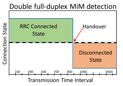
To perform the attack, the MiM also needs to ensure that there is no direct link between the base station and the mobile device. To achieve this goal, the MiM can either operate on different frequencies or transmit at a much higher power to attack a mobile device that is far away from the base station. Since the MiM is unaware of the change in frequency and since the neighbor base station cannot reach the mobile device directly, the mobile device loses connectivity after attempting to handover. The ”Radio Resource Configuration (RRC)” state is used to monitor the ”Radio connected” state of the mobile device. When the mobile device has ongoing data traffic, the ”RRC” state remains in the ”Connected” state. The normal ”RRC” state toggles between Idle and Connected. As shown in Figure 18, prior to handover, the mobile device is in the ”Connected” state. When attempting to handover to a ghost base station, the mobile device disconnects from the base station and remains in that state for extended periods. The repository [45] maintains video demonstrations of the attack and detection of REVEAL protocol.
VII Discussion and Conclusion
In this study, we have proposed the REVEAL protocol as an agnostic wireless man-in-the-middle detection mechanism. Through our experiments, we have demonstrated that REVEAL is capable of detecting half, full, and double full duplex man-in-the-middle attacks. However, it should be noted that the REVEAL protocol is not able to predict when or which type of attack is ongoing, as the MiM can launch an attack at any time. Therefore, the detection protocol needs to be continuously run to monitor the network for potential attacks. Network operators can integrate the REVEAL protocol into their traffic scheduling policies to enhance network security and prevent unauthorized access.
Acknowledgements This material is based upon work partially supported by the US Army under W911NF-22-1-0151 and W911NF2120064, US Office of Naval Research under N00014-21-1-2385, and Department of Homeland Security under 70RSAT20CB0000017.
References
- [1] J. T. Chiang, J. J. Haas, Y. C. Hu, P. R. Kumar, and J. Choi, “Fundamental limits on secure clock synchronization and man-in-the-middle detection in fixed wireless networks,” in IEEE INFOCOM 2009, 2009, pp. 1962–1970.
- [2] H. I. Cho and G. U. Hwang, “Packet delay analysis of a wireless network with multiple relays under rayleigh fading channels,” in Proceedings of the 5th International Conference on Queueing Theory and Network Applications, ser. QTNA ’10. New York, NY, USA: Association for Computing Machinery, 2010, p. 59–66. [Online]. Available: https://doi.org/10.1145/1837856.1837866
- [3] G. Kramer, M. Gastpar, and P. Gupta, “Cooperative strategies and capacity theorems for relay networks,” IEEE Transactions on Information Theory, vol. 51, no. 9, pp. 3037–3063, 2005.
- [4] S. Erni, M. Kotuliak, P. Leu, M. Roeschlin, and S. Capkun, “Adaptover: Adaptive overshadowing attacks in cellular networks,” in Proceedings of the 28th Annual International Conference on Mobile Computing And Networking, ser. MobiCom ’22. New York, NY, USA: Association for Computing Machinery, 2022, p. 743–755. [Online]. Available: https://doi.org/10.1145/3495243.3560525
- [5] D. Rupprecht, K. Kohls, T. Holz, and C. Pöpper, “Breaking lte on layer two,” in 2019 IEEE Symposium on Security and Privacy (SP), 2019, pp. 1121–1136.
- [6] 3GPP RAN1, “LTE physical layer procedures,” 2023. [Online]. Available: https://www.etsi.org/deliver/etsi_ts/136200_136299/136213/14.02.00_60/ts_136213v140200p.pdf
- [7] 3GPP working group, “Cellular Standards.” [Online]. Available: https://www.3gpp.org/specifications-technologies/specifications-by-series
- [8] S. Ganji, “Full duplex man-in-the-middle implementation,” 2023. [Online]. Available: https://anonymous.4open.science/r/infinitelooper-08F0/README.md
- [9] V. Kumar, S. Chakraborty, F. A. Barbhuiya, and S. Nandi, “Detection of stealth Man-in-the-Middle attack in wireless LAN,” in 2012 2nd IEEE International Conference on Parallel, Distributed and Grid Computing, Dec. 2012, pp. 290–295.
- [10] H. Hwang, G. Jung, K. Sohn, and S. Park, “A study on mitm (man in the middle) vulnerability in wireless network using 802.1x and eap,” in 2008 International Conference on Information Science and Security (ICISS 2008), 2008, pp. 164–170.
- [11] M. Lynn and R. Baird, “Advanced 802.11 attack,” 2002. [Online]. Available: http://www.blackhat.com/presentations/bh-usa-02/baird-lynn/bh-us-02-lynn-802.11attack.ppt
- [12] N. Cam-Winget, R. Housley, D. Wagner, and J. Walker, “Security flaws in 802.11 data link protocols,” Communications of the ACM, vol. 46, no. 5, pp. 35–39, 2003.
- [13] D. Bradbury, “Hacking wifi the easy way,” Network Security, vol. 2011, no. 2, pp. 9–12, 2011.
- [14] M. S. Ahmad, “Wpa too!” DEF CON, vol. 18, 2010.
- [15] A. Herzberg and H. Shulman, “Stealth-mitm dos attacks on secure channels,” arXiv preprint arXiv:0910.3511, 2009.
- [16] M. Agarwal, S. Biswas, and S. Nandi, “Advanced stealth man-in-the-middle attack in wpa2 encrypted wi-fi networks,” IEEE Communications Letters, vol. 19, no. 4, pp. 581–584, 2015.
- [17] V. Kumar, S. Chakraborty, F. A. Barbhuiya, and S. Nandi, “Detection of stealth man-in-the-middle attack in wireless lan,” in 2012 2nd IEEE International Conference on Parallel, Distributed and Grid Computing, 2012, pp. 290–295.
- [18] D. Steinmetzer, Y. Yuan, and M. Hollick, “Beam-stealing: Intercepting the sector sweep to launch man-in-the-middle attacks on wireless ieee 802.11ad networks,” in Proceedings of the 11th ACM Conference on Security and Privacy in Wireless and Mobile Networks, ser. WiSec ’18. New York, NY, USA: Association for Computing Machinery, 2018, p. 12–22. [Online]. Available: https://doi.org/10.1145/3212480.3212499
- [19] D. Strobel, “Imsi catcher,” Chair for Communication Security, Ruhr-Universität Bochum, vol. 14, 2007.
- [20] U. Meyer and S. Wetzel, “A man-in-the-middle attack on umts,” in Proceedings of the 3rd ACM Workshop on Wireless Security, ser. WiSe ’04. New York, NY, USA: Association for Computing Machinery, 2004, p. 90–97. [Online]. Available: https://doi.org/10.1145/1023646.1023662
- [21] J. G. Beekman and C. Thompson, “Breaking cell phone authentication: Vulnerabilities in aka, ims and android,” in Proceedings of the 7th USENIX Conference on Offensive Technologies, ser. WOOT’13. USA: USENIX Association, 2013, p. 5.
- [22] M. Chlosta, D. Rupprecht, T. Holz, and C. Pöpper, “Lte security disabled: Misconfiguration in commercial networks,” in Proceedings of the 12th Conference on Security and Privacy in Wireless and Mobile Networks, ser. WiSec ’19. New York, NY, USA: Association for Computing Machinery, 2019, p. 261–266. [Online]. Available: https://doi.org/10.1145/3317549.3324927
- [23] A. Shaik, R. Borgaonkar, S. Park, and J.-P. Seifert, “New vulnerabilities in 4g and 5g cellular access network protocols: Exposing device capabilities,” in Proceedings of the 12th Conference on Security and Privacy in Wireless and Mobile Networks, ser. WiSec ’19. New York, NY, USA: Association for Computing Machinery, 2019, p. 221–231. [Online]. Available: https://doi.org/10.1145/3317549.3319728
- [24] N. Ludant and G. Noubir, “Sigunder: A stealthy 5g low power attack and defenses,” in Proceedings of the 14th ACM Conference on Security and Privacy in Wireless and Mobile Networks, ser. WiSec ’21. New York, NY, USA: Association for Computing Machinery, 2021, p. 250–260. [Online]. Available: https://doi.org/10.1145/3448300.3467817
- [25] D. Rupprecht, K. S. Kohls, T. Holz, and C. Pöpper, “Imp4gt: Impersonation attacks in 4g networks,” in Network and Distributed System Security Symposium, 2020.
- [26] T. Kim, H. Park, H. Jung, and H. Lee, “Online detection of fake access points using received signal strengths,” in 2012 IEEE 75th Vehicular Technology Conference (VTC Spring), 2012, pp. 1–5.
- [27] W. Wei, K. Suh, B. Wang, Y. Gu, J. Kurose, and D. Towsley, “Passive online rogue access point detection using sequential hypothesis testing with tcp ack-pairs,” in Proceedings of the 7th ACM SIGCOMM Conference on Internet Measurement, ser. IMC ’07. New York, NY, USA: Association for Computing Machinery, 2007, p. 365–378. [Online]. Available: https://doi.org/10.1145/1298306.1298357
- [28] R. Beyah, S. Kangude, G. Yu, B. Strickland, and J. Copeland, “Rogue access point detection using temporal traffic characteristics,” in IEEE Global Telecommunications Conference, 2004. GLOBECOM ’04., vol. 4, 2004, pp. 2271–2275 Vol.4.
- [29] H. Han, B. Sheng, C. C. Tan, Q. Li, and S. Lu, “A timing-based scheme for rogue ap detection,” IEEE Transactions on Parallel and Distributed Systems, vol. 22, no. 11, pp. 1912–1925, 2011.
- [30] G. Qu and M. N. Michael, “Rapid: An indirect rogue access points detection system,” in International Performance Computing and Communications Conference, 2010, pp. 9–16.
- [31] R. Beyah, S. Kangude, G. Yu, B. Strickland, and J. Copeland, “Rogue access point detection using temporal traffic characteristics,” in IEEE Global Telecommunications Conference, 2004. GLOBECOM ’04., vol. 4, 2004, pp. 2271–2275 Vol.4.
- [32] IEEE, “IEEE wired and wireless Standards.” [Online]. Available: https://ieeexplore.ieee.org/browse/standards/get-program/page/series?id=68
- [33] Bluetooth Special Interest Group, “Bluetooth® Technology specifications.” [Online]. Available: https://www.bluetooth.com/specifications/specs/
- [34] 3GPP, “Newradio physical layer procedures for control,” 2023. [Online]. Available: https://www.etsi.org/deliver/etsi_ts/138200_138299/138213/15.05.00_60/ts_138213v150500p.pdf
- [35] D. B. Sullivan, D. W. Allan, D. A. Howe, D. Sullivan, and F. Walls, “Characterization of clocks and oscillators,” 1990.
- [36] N. M. Freris, S. R. Graham, and P. R. Kumar, “Fundamental limits on synchronizing clocks over networks,” IEEE Transactions on Automatic Control, vol. 56, no. 6, pp. 1352–1364, 2011.
- [37] J. C. Eidson, M. Fischer, and J. White, “Ieee-1588™ standard for a precision clock synchronization protocol for networked measurement and control systems,” in Proceedings of the 34th Annual Precise Time and Time Interval Systems and Applications Meeting, 2002, pp. 243–254.
- [38] A. Ghosh and R. Ratasuk, Essentials Of Lte And Lte-A. Cambridge University Press, 2011.
- [39] A. K. Thyagarajan, P. Balasubramanian, V. D, and K. M, “Snr-cqi mapping for 5g downlink network,” in 2021 IEEE Asia Pacific Conference on Wireless and Mobile (APWiMob), 2021, pp. 173–177.
- [40] srsRAN Project, “open source 4g software radio suite,” Jan 2023. [Online]. Available: https://github.com/srsran/srsRAN_4G
- [41] Ettus Research, “Usrp x310,” Jan 2023. [Online]. Available: https://www.ettus.com/all-products/X310-KIT/
- [42] Ettus Research., “Usrp b210,” Jan 2023. [Online]. Available: https://www.ettus.com/all-products/ub210-kit/
- [43] D. Bharadia, E. McMilin, and S. Katti, “Full duplex radios,” SIGCOMM Comput. Commun. Rev., vol. 43, no. 4, p. 375–386, aug 2013. [Online]. Available: https://doi.org/10.1145/2534169.2486033
- [44] open cellid org., “The world’s largest open database of cell towers,” Jan 2023. [Online]. Available: https://www.opencellid.org/#zoom=16&lat=37.77889&lon=-122.41942
- [45] Santosh Ganji., “Demonstration videos of the working system,” Jan 2023. [Online]. Available: https://github.com/shotsan/MiM_paper_demo_videos/tree/main