2023
[1]\fnmKaiyi \surWu \equalcontThese authors contributed equally to this work.
These authors contributed equally to this work.
1]\orgdivSchool of Electrical and Computer Engineering, \orgnamePurdue University, \orgaddress\cityWest Lafayette, \postcode47907, \stateIN, \countryUSA
2]\orgdivDepartment of Microtechnology and Nanoscience, \orgnameChalmers University of Technology, \orgaddress\streetSE-41296, \countrySweden
3]\orgdivCurrently with Department of Surgery, \orgnameUniversity of Pittsburgh, \orgaddress\postcode15219, \statePA, \countryUSA
4]\orgdivElectrical Engineering Department, \orgnameKing Saud University, \orgaddress\cityRiyadh, \postcode11421, \countrySaudi Arabia
5]\orgdivCurrently with Torch Technologies, \orgnamesupporting AFRL/RW, \orgaddress\cityEglin Air Force Base, \stateFL, \countryUSA
Vernier Microcombs for Integrated Optical Atomic Clocks
Abstract
CMOS-compatible Kerr microcombs have drawn substantial interest as mass-manufacturable, compact alternatives to bulk frequency combs. This could enable deployment of many comb-reliant applications previously confined to laboratories. Particularly enticing is the prospect of microcombs performing optical frequency division in compact optical atomic clocks. Unfortunately, it is difficult to meet the self-referencing requirement of microcombs in these systems due to the THz repetition rates typically required for octave-spanning comb generation. Additionally, it is challenging to spectrally engineer a microcomb system to align a comb mode with an atomic clock transition with sufficient signal-to-noise ratio. Here, we adopt a Vernier dual-microcomb scheme for optical frequency division of a stabilized ultranarrow-linewidth continuous-wave laser at 871 nm to a 235 MHz output frequency. In addition to enabling measurement of the comb repetition rates, this scheme brings the freedom to pick comb lines from either or both of the combs. We exploit this flexibility to shift an ultra-high-frequency (100 GHz) carrier-envelope offset beat down to frequencies where detection is possible and to place a comb line close to the 871 nm laser - tuned so that if frequency-doubled it would fall close to the clock transition in 171Yb+. Moreover, we introduce a novel scheme which suppresses frequency noise arising from interferometric phase fluctuations in our dual-comb system and reduces the frequency instability down to our measurement limit. Our dual-comb system can potentially combine with an integrated ion trap toward future chip-scale optical atomic clocks.
keywords:
Frequency combs, optical atomic clocks, integrated photonics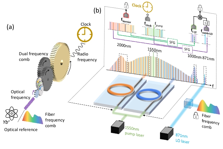
By virtue of their extreme long-term frequency stability, optical atomic clocks promise to revolutionize timing systems, enable fundamental tests of physics godun2014frequency , and allow chronometric leveling and geodesy takano2016geopotential ; riehle2017optical . Lab-scale optical lattice clocks campbell2017fermi ; collaboration2021frequency and ion trap clocks brewer2019al+ ; collaboration2021frequency can provide state-of-the-art frequency stability. However, scaling these clocks to a low size, weight, and power (SWaP) architecture is an important and challenging hurdle preventing significant deployment of the highest-performing optical atomic clock technology. Efforts such as ivory2021integrated ; ropp2023integrating toward integrated ion traps and optical lattices illustrate recent progress toward high-stability, chip-scale optical atomic clocks.
Microcombs are an essential part of future chip-scale optical atomic clocks papp2014microresonator ; newman2019architecture as they establish a coherent link from atomic references at hundreds of THz all the way down to the RF domain (analogous to a gear set - Fig. 1a diddams2020optical ) while preserving the stability of an atom-referenced clock laser. The realization of this coherent link is referred to as optical frequency division (OFD). The comb’s optical modes are equally spaced by the repetition rate (usually an RF frequency), and the whole comb has a spectral offset (the carrier-envelope offset [CEO] frequency, ) so that . The RF mode spacing of optical modes in a comb is key to enabling the bridge between optical and RF domains. Historically frequency combs in optical atomic clocks have often been generated by modelocked lasers diddams2001optical ; ye2001molecular that have volumes on the order of liters, and generally require at least a measure of hand assembly, complicating mass production and increasing costs. Shrinking down these combs should be helpful toward miniaturizing optical atomic clocks and other systems requiring stabilized combs, and can be achieved through frequency comb generation in Kerr microresonators on complementary metal-oxide semiconductor (CMOS)-compatible photonic chips kippenberg2018dissipative .
Unfortunately, Kerr microcombs possessing the octave span needed for self-referencing (a requirement for many OFD applications) typically have THz repetition rates. This leads to in the range of GHz, which is difficult to control because of microring fabrication imperfections yu2019tuning ; moille2021tailoring ; as a result, the beat is frequently too high for electronic detection. In part due to these issues, microcomb-based OFD remains a challenging task. The only two demonstrations papp2014microresonator ; newman2019architecture of microcomb-based OFD of an atom-referenced laser, to our knowledge, relied on low repetition rate (tens of GHz), narrowband combs generated from mm-size whispering gallery mode silica microdisk resonators, either spectrally broadened in a nonlinear fiber papp2014microresonator or used in conjunction with a secondary, broadband silicon nitride THz-microcomb newman2019architecture . Both of these works utilized thermal vapors for the atomic reference, not cooled or trapped atoms.
In this work, we demonstrate an integrated photonic platform based on Vernier dual-microcombs that overcomes some of the fundamental challenges of previous microcomb-based systems for the realization of chip-scale optical clocks. Specifically, by pairing a main octave-spanning THz-microcomb with a secondary broadband THz Vernier microcomb, both on a silicon nitride (SiN) platform, we successfully frequency divide an ultranarrow-linewidth CW laser at 871 nm lai2021871nm to an RF clock output at 235 MHz. This laser is designed for frequency-doubling to within a few GHz of the Ytterbium ion (171Yb+) “clock transition” at 435.5 nm that is expected to support better frequency stability than most thermal atomic references. By virtue of its dual broadband combs, the Vernier scheme used here presents a substantial advantage over single broadband comb schemes. One of the advantages is the freedom of picking comb lines from either or both of the combs for frequency-summing to aid in reaching a much greater variety of wavelengths Wu2023vernier . Here this is adopted both to help circumvent the high-frequency detection problem and to reach 871 nm by frequency-summing the pump and one of the secondary comb’s lines at 2m. While we focus on this transition, we emphasize the generality of the technique to reach a variety of other atomic transitions for future optical clocks. In addition, with both THz-microcombs fabricated in SiN films of the same thickness, there is potential to integrate our scheme on a single chip. Since the area of a microring scales as the square of its diameter (inverse square of the comb repetition rate), the footprint of a dual THz-microcomb structure could be several orders of magnitude smaller than that of architectures employing GHz microcombs. Furthermore, the all-planar geometry employed here avoids the complexity involved in coupling to suspended whispering gallery mode resonators or integrating the same yang2018bridging . These results demonstrate a versatile and general microcomb platform for the realization of chip-scale optical atomic clocks.
Results
Dual-microcomb scheme. The overview of our experiment configuration is visualized in Fig. 1b. An ultra-narrow linewidth 871 nm (344 THz) continuous wave (CW) laser (LO laser) developed by OEwaves lai2021871nm ; lai2022ultra is phase-locked to an external self-referenced fiber comb (FC, Menlo systems), which here serves as a frequency-stable proxy for a potential Yb+ frequency reference (which is not available in our laboratory). Our microcomb system is built on the Vernier dual-microcomb scheme wang2020vernier ; Wu2023vernier , which is leveraged here for full optical frequency division for the first time. Two broadband microcombs with large repetition rates (900 GHz), slightly offset from one another ( 20 GHz), are generated with a shared CW pump. This configuration has been shown to allow detection of both large and Wu2023vernier . We aim to transfer the LO laser stability to an RF clock output using a heterodyne beat in the dual-microcomb system.
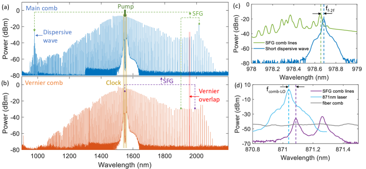
We utilize a pair of microrings with 25 m radius, fabricated in SiN ye2019high , to generate our microcombs. The main comb is designed to have dispersive waves at 1 m and 2 m wavelengths to assist the f-2f process, while the Vernier comb should have a resonance wavelength close to that of the main comb to allow for a shared pump. We select microrings fabricated on separate chips but the same wafer. A single CW laser around 1550 nm is amplified and split to pump both the main and Vernier devices simultaneously, generating an octave-spanning coherent frequency comb in each. Figure 2a,b show the spectra for the main and Vernier combs. The main (Vernier) comb possesses a repetition rate 896 GHz (876 GHz). As a result of the shared pump, when the first sidebands from each comb are heterodyned together on a photodetector, they create an electronic signal oscillating at the difference of the two repetition rates (see Fig.1b). We call this signal , where
| (1) |
and through appropriate feedback to our two combs, seek to transfer the stability of the 344 THz LO laser to this 19.7 GHz dual-comb beat.
In order to accomplish OFD from the LO laser to , at a minimum, we need to stabilize the two repetition rates to the LO laser, and thus several optical signals must be photodetected and stabilized. We separate the 1 m, 1.55 m and 2 m spectral components and combine the dual-comb spectra at 1.55 m and 2 m wavelengths for the detection of various heterodyne beats. The spectral domain schematic is illustrated in Fig. 1b. A detailed experimental setup can be found in Methods. Due to their different repetition rates, the two combs walk off from each other as one moves away from the pump, eventually coming back together at the so-called Vernier overlap point. The comb modes at this point can be photodetected (here, around 1956 nm) to produce a relatively low-frequency beat:
| (2) |
With this signal phase-locked through feedback to the Vernier comb, will follow omalley2022vernier . We still need to stabilize the two repetition rates to the LO laser through feedback to the main comb to achieve a fully stabilized , the difference of the two repetition rates.
We perform a novel f-2f process via sum-frequency generation (SFG) Wu2023vernier in a periodically-poled lithium niobate (PPLN) waveguide, which sums one comb line from each comb at around 2 m (). The sum products are combined with the short-wavelength side of the main comb around 1 m () to create an f-2f-like beat signal, . Fig. 2c shows the sample spectra of the sum products and the short wavelength line. This f-2f beat contains contributions from not only the CEO frequency of one of the combs but also the two repetition rates:
| (3) |
Finally, to relate the dual-microcombs to the stable 871nm LO laser, which is outside the span of both comb spectra, we use a second PPLN waveguide for SFG between the 1550nm-pump () and a long-wavelength comb line (1990 nm) from the Vernier comb to create a nonlinear product. The LO laser at is tuned to 871.042nm to beat against the SFG product to create , and we have
| (4) |
The sample spectra for the SFG lines and the LO laser can be seen in Fig. 2d. This SFG process benefits from the high power of the pump and the optically amplified 2 m comb line, leading to a reasonable SFG power of -36 dBm. We note that as a result of the common pump condition (), the and beats in Eq. 3, 4 can be expressed in terms of either or .
As both and contain the term, but with a fixed ratio of 1:2, we can cancel the CEO term through electronic frequency division and frequency mixing:
| (5) |
We refer to the frequency of the resulting signal as , since ideally, contributions from both combs’ are removed. Instead, depends on the two combs’ repetition rates and relates them to the LO laser. If we lock this signal through feedback to the main comb and simultaneously lock by feedback to the Vernier comb, the repetition rates will each be stabilized to the LO laser. Furthermore, as a consequence of the stabilized repetition rates and the common pump frequency, should be stabilized as well, completing the clock frequency division. Importantly, this is irrespective of the free-running CEO frequencies of both combs. This simplifying scheme allows us to construct our clock system with two servos, removing requirements for a third servo to stabilize the offset frequency. In the experiment, we generate due to electronic component availability.
Microcomb Stabilization. To achieve the clock frequency division from the optical reference, we first stabilize the 871 nm LO laser to one optical line from a stable fiber comb through an offset phase lock referenced to an RF oscillator, where the offset frequency 910 MHz is defined as
| (6) |
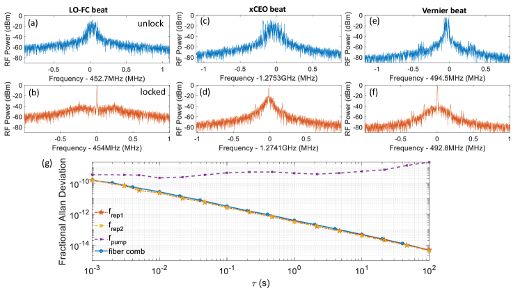
We then phase lock the and beats to two other RF oscillators by feedback to the pump power of the main and Vernier combs, respectively, using intensity modulators before input-coupling to the two microrings. This stabilization scheme without CEO frequency locking avoids tuning the pump frequency and intensity simultaneously, which may introduce crosstalk between repetition rate and CEO frequency control del2016phase . Figures 3 a-f show the electrical spectrum analyzer (ESA) traces of the three beats before and after phase-locking. The three oscillators for the offset locks, the fiber comb, and the frequency stability testing utilities are all synchronized to a common GPS-disciplined high-stability ovenized quartz oscillator (OCXO) to eliminate relative drifting. In principle, this sync signal could instead be derived from an atomic reference, as in diddams2001optical .
To verify the repetition rates for both microcombs are stabilized to the optical reference (fiber comb), we conduct out-of-loop measurements using an electro-optic (EO) frequency comb metcalf2013high to downshift the repetition rates to an electronically detectable range. The time traces of the repetition rates are recorded by a zero dead-time frequency counter running at 1 ms gate time. We calculate the fractional Allan deviation of the two repetition rates, as shown in Fig. 3g. The frequency stability of the fiber comb is also obtained by measuring its 250 MHz-repetition-rate beat note using a phase noise test set (PNTS), as the blue trace in Fig. 3g shows. This is an estimate of the fractional frequency instability of the optical modes of the fiber comb (see supplementary).
Both microcomb repetition rates follow the optical reference, indicating the stability of the LO laser has been successfully transferred to the two THz repetition rates. Note that neither microcomb is fully stabilized because the CEO frequencies of both combs are still free-running. We demonstrate this by beating the pump line with a fiber comb line at 1550 nm and recording the output with a frequency counter. The result is shown as the purple trace in Fig. 3g, which has frequency instability that increases with increased averaging time (). Clearly, without stabilizing the CEO frequencies, individual microcomb lines drift over time. Nevertheless, with the stabilized repetition rates, we anticipate a frequency division effect from the optical reference to , following the expression derived from the relations between the detected beats (see Supplementary for details)
| (7) |
The fractional frequency instability of the clock output also matches that of the optical reference as a result.
RF Clock Performance. We characterized the fractional frequency instability of the RF clock output with the PNTS. The results are shown in Fig. 4a. Although initially, the fractional instability (orange line, “initial clock”) does come down approximately inversely with (as expected), it shows excess noise with 5 higher fractional instability than our system floor (blue line, “fiber comb”) and plateaus at a value of for 1 sec and beyond. A similar effect has been reported in other recent works zang2020millimeter ; drake2019terahertz but was not investigated therein. We attribute this excess noise to time-varying phase perturbations in the fiber leads that bring light in and out of the individual microrings. Related noise effects are well known in the distribution of ultra-stable frequency references and coherent optical carriers over fiber links and are usually addressed by feedback control to an acousto-optic (AO) frequency shifter in order to stabilize a heterodyne beat involving two-way propagation through both the AO and the fiber link foreman2007remote ; newbury2007coherent . Here we introduce a novel open-loop electronic mixing technique that reduces the excess noise from our clock signal without the need for two-way propagation and brings the frequency instability down to a level near our system floor, explained below.
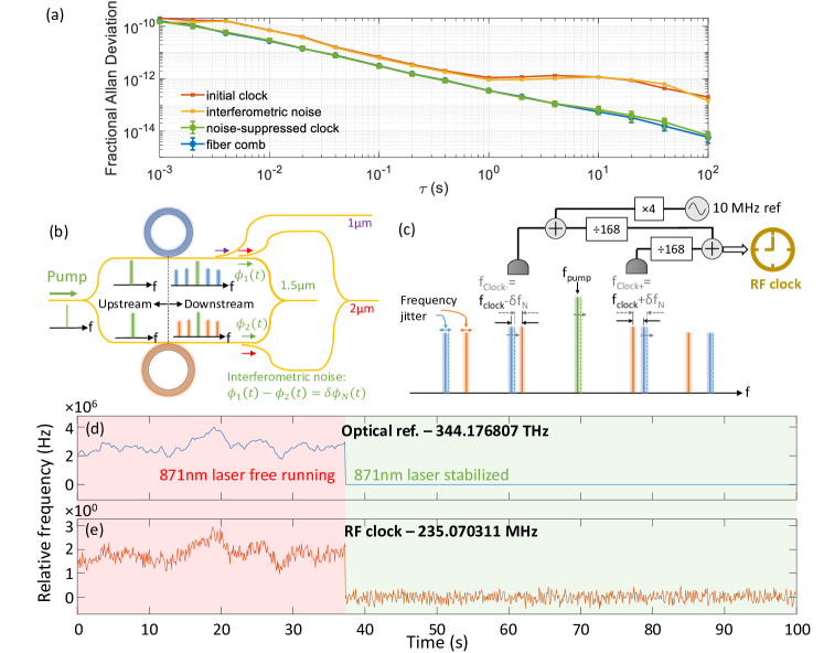
A simplified dual-comb configuration is sketched in Fig. 4b, where a single pump is split into two paths for generating both combs, and the comb lines from both combs are combined together to generate a heterodyne beat signal for the RF clock output. This structure resembles an interferometer, which is sensitive to phase perturbations in either of its arms. We represent the phase fluctuations in the upper and lower arms as and , respectively. is comprised of the time-varying phase experienced by the pump in the interferometer arm upstream of the main ring plus the phase picked up by the comb line of interest downstream from the main ring; is defined similarly but refers to the leads connecting the Vernier ring. The heterodyne beat can be generated by photodetecting the first sidebands at either side of the pump, as illustrated in Fig. 4c. We term these and , corresponding to the higher and lower frequency side of the pump, respectively:
| (8) |
| (9) |
where represents the time-derivative of . These expressions take into account the frequency fluctuations that arise in proportion to the derivative of the time-varying phases weiner2011ultrafast . Since and may be uncorrelated, they give rise to frequency noise on the clock signal. Critically, the frequency noise on and is equal and opposite in the expressions above. By summing and with an electronic mixer
| (10) |
we can ideally suppress the frequency noise completely. Note that the formulation above ignores any noise contributed by the electronics and approximates the phase shifts incurred by comb lines ±1 in the fiber leads downstream of the resonators as equal. Since the frequencies of the ±1 modes differ from the pump frequency by only a small fractional amount, the error involved in this approximation is small.
We implement this differential noise suppression scheme by detecting and on separate photodetectors in parallel and frequency-mixing the resulting heterodyne beats (see Fig. 4c). In practice, we mix a frequency-divided and a copy of upshifted by 40 MHz and subsequently frequency-divided by 168 (see Fig 4c - more details in Methods). The result is a noise-suppressed RF clock output at 235 MHz.
To demonstrate frequency division, we measure the frequency of the optical reference and the RF clock output as a function of time using two synchronized counters with the two repetition rate locks in place. The results are plotted in Figs. 4d,e. The y-axis span of the optical reference is exactly 1729284 times that of the RF clock, corresponding to the optical frequency division factor of 17292 (Eq. LABEL:eq_freqdiv) and the electronic division factor of 84 (= 168/2) for bringing down the clock frequency to within counter and electronic mixer ranges. The 871 nm LO laser is initially free-running, and we switch on the lock to the fiber comb midway through the measurement. The RF clock frequency follows that of the LO laser, both when the 871 nm laser is free-running and when it is locked. Further details, including a discussion of the fluctuations in the RF clock trace, can be found in the Supplement.
The fractional Allan deviation of our 235 MHz noise-suppressed RF clock output, measured using the PNTS, is plotted as part of Fig. 4a (green trace). The frequency instability is substantially reduced, now essentially overlaying with the estimated fractional Allan deviation of the frequency comb reference for the LO laser, which determines our measurement floor. These results signify that the frequency stability of the 344 THz LO laser has been successfully transferred to our 235 MHz RF clock. Our method also allows us to extract the differential-mode interferometric frequency noise directly (see Methods), which we also plot in Fig.4a (yellow trace). It roughly overlays with the red trace representing the fractional frequency instability of the initial clock output. This supports our attribution of the excess noise present in the clock prior to the suppression scheme to differential mode interferometric phase variations.
Discussion
We have demonstrated the use of a Vernier dual-microcomb system to frequency-divide a compact, ultra-narrow linewidth CW laser at 871 nm down to an RF output of 235 MHz using only two feedback servos, enabled in part by an interferometric noise suppression scheme. The CW laser at 871 nm is within a few GHz of being able to be frequency-doubled to a clock transition of a Ytterbium ion.
The Vernier dual-microcomb OFD platform used here is useful for detecting high-frequency and potentially for performing OFD on a variety of atomic species through a dual-comb sum-frequency process. With the continued advancement of microcomb system integration capabilities rao2021towards , in the future, our dual combs can potentially be integrated onto a single SiN chip, together with on-chip thermal heaters for spectral alignment and microcomb feedback, and spectral filtering for separation and routing of different wavelength bands. Furthermore, there has been exciting progress in heterogeneous integration of III-V xiang2021laser ; xiang2023three and thin-film lithium niobate churaev2023heterogeneously ; ruan2023high materials on the SiN platform. These may enable integration of III-V lasers for microcomb pumping and PPLN for second-order nonlinear frequency conversion towards a fully integrated dual-comb system in the future. Additionally, through the elimination of many of the fibers used in our current experiment, such a system should be much less sensitive to environmental perturbations.
With further advances in compact ion traps and optical lattices ivory2021integrated ; setzer2021fluorescence ; niffenegger2020integrated ; ropp2023integrating , we anticipate that our dual-microcomb system, paired with an integrated atomic reference and compact narrow linewidth laser, may one day enable a fully-integrated high-performance optical atomic clock.
Methods
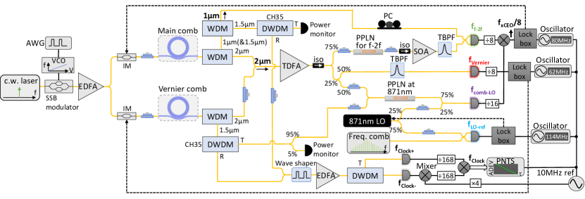
Experimental Setup. The experimental setup can be found in the Fig. 5. We use a single-sideband modulator to rapidly frequency-sweep stone2018thermal a 1550 nm external cavity diode laser (ECDL) (Toptica CTL 1550) pump into resonance for both microrings simultaneously, generating microcombs in each. The two resonators are frequency-aligned using thermo-electric temperature control units. After comb generation is initiated, the pump frequency is adjusted through piezoelectric control of the ECDL towards a longer wavelength to optimize the dispersive wave conditions of the microcombs, so that the short wavelength dispersive wave of the main comb falls within the conversion wavelength of our available fiber-pigtailed PPLN waveguide (HC Photonics). In this dispersive wave state, we also make use of the long wavelength dispersive wave of the main comb, which benefits the SFG process for f-2f. A network of fiber optical filters and couplers are employed to separate spectral bands at 1550 nm, 2000 nm, and 1000 nm and combine the dual-comb spectra at 1550 nm and 2000 nm. For the results shown in the main text, we have introduced foam partitions to cover most of our setup to reduce noise effects due to air currents and the like (further discussion in the Supplement).
The combined 2000nm spectral components are amplified using a thulium-doped fiber amplifier and then distributed in three arms for (a) the SFG process for f-2f, (b) the SFG process to hit 871nm via combining with the 1550nm residual pump from the Vernier comb, and (c) the Vernier beat detection. The SFG products for f-2f are subsequently amplified by a semiconductor optical amplifier (SOA, Innolume) and filtered by a 1nm-bandwidth bandpass filter (Photonwares) to suppress the broadband amplified spontaneous emission noise. It is then combined with the 1000 nm light from the main comb to generate the f-2f beat using a balanced photodetector (BPD). The SFG products at 871nm from the Vernier comb are combined with 25% of the 871nm LO laser using a 75:25 coupler to generate , with -36 dBm of SFG (spectrum shown in Fig. 2) and -4.5 dBm of laser power measured at the photodetector. 75% of the LO laser is combined with the fiber comb (bandpass-filtered at 871nm) using a 50:50 coupler and is detected on another BPD, with 3 dBm of LO power and -56 dBm power per fiber comb line at one arm of the BPD (where the laser and fiber comb spectra in Fig. 2(d) are measured). The clocks at both sides of the pump are selected by a programmable waveshaper (Finisar), optically amplified in the same EDFA, and separated with DWDM filters for detection on two distinct PDs.
The Vernier beat detected by an amplified PD is divided by 8 and sent to an offset phase lock servo (Vescent D2-135). The locked offset frequency is times the reference frequency generated by a stable oscillator (Agilent E8257D) synchronized to the 10 MHz GPS-disciplined oscillator (here, =16). We obtain by mixing divided by 8 and divided by 16. This beat is sent to another phase lock servo with set to 32. The reference signal is generated by another synchronized oscillator (Keysight 33220A). Finally, for our frequency instability measurements, we use frequency counters (Keysight 53230A) and a phase noise test set (Microsemi 5125A), which will be discussed in the next section.
Noise-Suppressed RF Clock. Our noise suppression scheme relies on mixing and to cancel differential-mode noise in the RF clock output. Due to the availability of components, we mix frequency-divided versions of these two signals in practice ( and ). Importantly, the sum of these two signals is almost exactly equal to the second harmonic of either (that is, ). This means it is impossible to filter out the undesirable second harmonics originating in the mixer and get the pure sum-frequency signal, thus still resulting in excess noise. To avoid this problem, we frequency shift one of the clocks by mixing with the 40 MHz signal (generated by twice-doubling the 10 MHz GPS-disciplined reference) to obtain , filtered by a 30 MHz-bandwidth Yttrium Iron Garnet (YIG) bandpass filter. This frequency-up-shifted clock is being divided and electronically mixed with the other divided clock to realize at the output. The desired sum-frequency output is then distinguishable from harmonics of either of the mixer inputs. Although the second harmonic and other products still exist and are spaced by a 238 kHz (40MHz/168), the desired noise-suppressed output is 20 dB higher than the other products and the PNTS can track the desired signal (see Supplementary for RF spectrum). Importantly, we note that the 10 MHz reference used here to shift one of the clock products should in principle be able to be derived from an optical reference if our system were to perform OFD on an atomic specimen (somewhat similar to diddams2001optical ). This would remove the need for a GPS-referenced 10 MHz sync signal in order to operate the OFD system.
For Fig. 4d we measure the frequency traces of the optical reference and the RF clock output simultaneously on two synchronized frequency counters running at 100 ms gate time with the same trigger signal and external gate. The optical reference frequency is obtained by recording and calculating using Eq. 6. We attribute the larger frequency fluctuations in the RF clock trace compared with the optical reference to the spurious frequency content in the output signal. Although the weak spurs cause no significant problem for the PNTS (see Fig. 4a), they do result in a few times increase in the frequency fluctuations reported by the frequency counter. See the Supplement for further discussion.
The Allan deviation for the RF clock output and the fiber comb reference were taken several times over multiple days. The symbols and error bars plotted in Fig. 4a represent the averages and standard deviations from multiple measurement results. The error bars are relatively tight, indicating good repeatability.
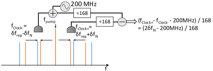
Interferometric noise extraction. The noise suppression scheme can be modified to extract the interferometric noise for direct measurement. As explained in the main text, by adding and the differential frequency noise can be made to cancel out. By measuring the difference between and , the clock term is cancelled and we obtain the frequency noise term . To implement the noise measurement, we frequency-up-shift one of the clocks by 200 MHz and divide it by 168, then frequency-mix with the other clock also divided by 168 (Fig. 6). This creates a frequency difference of 1.2 MHz out of the mixer, which is within the frequency range of our PNTS (1 - 400 MHz). The fractional instability of this signal filtered using a low-pass filter (normalized to the 235 MHz noise-suppressed clock frequency) is shown as the yellow curve in Fig. 4a and is similar to the curve for the clock output without noise suppression.
Data Availability
Data are available from the authors upon reasonable request.
References
- \bibcommenthead
- (1) Godun, R. et al. Frequency ratio of two optical clock transitions in yb+ 171 and constraints on the time variation of fundamental constants. Physical review letters 113 (21), 210801 (2014) .
- (2) Takano, T. et al. Geopotential measurements with synchronously linked optical lattice clocks. Nature Photonics 10 (10), 662–666 (2016) .
- (3) Riehle, F. Optical clock networks. Nature Photonics 11 (1), 25–31 (2017) .
- (4) Campbell, S. L. et al. A fermi-degenerate three-dimensional optical lattice clock. Science 358 (6359), 90–94 (2017) .
- (5) Boulder Atomic Clock Optical Network (BACON) Collaboration. Nature 591 (7851), 564–569 (2021) .
- (6) Brewer, S. M. et al. Al+ 27 quantum-logic clock with a systematic uncertainty below 10- 18. Physical review letters 123 (3), 033201 (2019) .
- (7) Ivory, M. et al. Integrated optical addressing of a trapped ytterbium ion. Physical Review X 11 (4), 041033 (2021) .
- (8) Ropp, C. et al. Integrating planar photonics for multi-beam generation and atomic clock packaging on chip. Light: Science & Applications 12 (1), 83 (2023) .
- (9) Papp, S. B. et al. Microresonator frequency comb optical clock. Optica 1 (1), 10–14 (2014) .
- (10) Newman, Z. L. et al. Architecture for the photonic integration of an optical atomic clock. Optica 6 (5), 680–685 (2019) .
- (11) Diddams, S. A., Vahala, K. & Udem, T. Optical frequency combs: Coherently uniting the electromagnetic spectrum. Science 369 (6501), eaay3676 (2020) .
- (12) Diddams, S. A. et al. An optical clock based on a single trapped 199hg+ ion. Science 293 (5531), 825–828 (2001) .
- (13) Ye, J., Ma, L. S. & Hall, J. L. Molecular iodine clock. Physical review letters 87 (27), 270801 (2001) .
- (14) Kippenberg, T. J., Gaeta, A. L., Lipson, M. & Gorodetsky, M. L. Dissipative kerr solitons in optical microresonators. Science 361 (6402), eaan8083 (2018) .
- (15) Yu, S.-P. et al. Tuning kerr-soliton frequency combs to atomic resonances. Physical Review Applied 11 (4), 044017 (2019) .
- (16) Moille, G., Westly, D., Orji, N. G. & Srinivasan, K. Tailoring broadband kerr soliton microcombs via post-fabrication tuning of the geometric dispersion. Applied Physics Letters 119 (12) (2021) .
- (17) Lai, Y.-H. et al. 871nm ultra-narrow-linewidth laser for yb+ clock. CLEO: Science and Innovations SF2P–3 (2021) .
- (18) Wu, K. et al. Vernier microcombs for high-frequency carrier envelope offset and repetition rate detection. Optica 10 (5), 626–633 (2023) .
- (19) Yang, K. Y. et al. Bridging ultrahigh-q devices and photonic circuits. Nature Photonics 12 (5), 297–302 (2018) .
- (20) Lai, Y.-H. et al. Ultra-narrow-linewidth lasers for quantum applications. CLEO: Science and Innovations STu5O–2 (2022) .
- (21) Wang, B., Yang, Z., Zhang, X. & Yi, X. Vernier frequency division with dual-microresonator solitons. Nature communications 11 (1), 3975 (2020) .
- (22) Ye, Z., Twayana, K., Andrekson, P. A. et al. High-q si3n4 microresonators based on a subtractive processing for kerr nonlinear optics. Optics express 27 (24), 35719–35727 (2019) .
- (23) O’Malley, N. P. et al. Vernier frequency combs for stabilization of rf/optical links. CLEO: Science and Innovations SW4O–2 (2022) .
- (24) Del’Haye, P. et al. Phase-coherent microwave-to-optical link with a self-referenced microcomb. Nature Photonics 10 (8), 516–520 (2016) .
- (25) Metcalf, A. J., Torres-Company, V., Leaird, D. E. & Weiner, A. M. High-power broadly tunable electrooptic frequency comb generator. IEEE Journal of Selected Topics in Quantum Electronics 19 (6), 231–236 (2013) .
- (26) Zang, J., Briles, T. C., Morgan, J. S., Beling, A. & Papp, S. Millimeter wave frequency synthesizer based on integrated photonics. 2020 International Topical Meeting on Microwave Photonics (MWP) 101–104 (2020) .
- (27) Drake, T. E. et al. Terahertz-rate kerr-microresonator optical clockwork. Physical Review X 9 (3), 031023 (2019) .
- (28) Foreman, S. M., Holman, K. W., Hudson, D. D., Jones, D. J. & Ye, J. Remote transfer of ultrastable frequency references via fiber networks. Review of scientific instruments 78 (2) (2007) .
- (29) Newbury, N. R., Williams, P. A. & Swann, W. C. Coherent transfer of an optical carrier over 251 km. Optics letters 32 (21), 3056–3058 (2007) .
- (30) Weiner, A. Ultrafast optics (John Wiley & Sons, 2011).
- (31) Rao, A. et al. Towards integrated photonic interposers for processing octave-spanning microresonator frequency combs. Light: Science & Applications 10 (1), 109 (2021) .
- (32) Xiang, C. et al. Laser soliton microcombs heterogeneously integrated on silicon. Science 373 (6550), 99–103 (2021) .
- (33) Xiang, C. et al. Three-dimensional integration enables ultra-low-noise, isolator-free si photonics. Preprint at https://arxiv.org/abs/2301.09989 (2023) .
- (34) Churaev, M. et al. A heterogeneously integrated lithium niobate-on-silicon nitride photonic platform. Nature Communications 14 (1), 3499 (2023) .
- (35) Ruan, Z. et al. High-performance electro-optic modulator on silicon nitride platform with heterogeneous integration of lithium niobate. Laser & Photonics Reviews 17 (4), 2200327 (2023) .
- (36) Setzer, W. et al. Fluorescence detection of a trapped ion with a monolithically integrated single-photon-counting avalanche diode. Applied Physics Letters 119 (15), 154002 (2021) .
- (37) Niffenegger, R. J. et al. Integrated multi-wavelength control of an ion qubit. Nature 586 (7830), 538–542 (2020) .
- (38) Stone, J. R. et al. Thermal and nonlinear dissipative-soliton dynamics in kerr-microresonator frequency combs. Physical review letters 121 (6), 063902 (2018) .
Funding
This work was funded in part by the DARPA APhI program, by AFOSR under grant FA9550-20-1-0283, and by the Swedish Research Council (VR 2020-00453). M.S.A. acknowledges support from the Researchers Supporting Project number (RSPD2023R613), King Saud University, Riyadh, Saudi Arabia.
Acknowledgements
The effort at Purdue under the DARPA APhI program was part of a project team lead by Sandia National Laboratories. The Si3N4 fabrication was done at Myfab Chalmers. The authors thank Scott Diddams, Scott Papp, Frank Quinlan, Xu Yi, and Beichen Wang for fruitful discussion. Jizhao Zang suggested the experiment shown in Supplementary Figure S2 for diagnosis of the phase noise issue. Mike Kickbush and Mohammed Abu Khater assisted in identifying appropriate YIG filters for our system. Hayden McGuinness kindly reviewed the manuscript prior to submission. Some of our earlier work on Vernier dual combs, such as dual-octave comb pairs, was presented at CLEO 2021 (SW2H.7), CLEO 2022 (SW4O.2), and CLEO 2023 (STh1J.4 and STh1J.5).
Author Contributions
A.M.W., M.S.A., and M.Q. devised the Vernier dual-comb scheme and initiated the project. K.W., N.P.O., and S.F. devised and conducted the experiments. C.W. designed the microring devices. M.G. and Z.Y. were responsible for fabrication of the microring devices, with oversight from V.T.-C.. D.E.L. was responsible for putting in place laboratory systems and advised on some of the experiments. A.M.W. supervised the project. A.M.W., K.W., N.P.O., and S.F. wrote the manuscript.
Conflicts of Interest
The authors declare no conflicts of interest.
Additional information
More experimental details and investigations can be found in the Supplemental document.