Present affiliation:]Miraex SA, Écublens, Switzerland
Unit cell of a Penning micro-trap quantum processor
Abstract
Trapped ions in radio-frequency traps are among the leading approaches for realizing quantum computers, due to high-fidelity quantum gates and long coherence times. However, the use of radio-frequencies presents a number of challenges to scaling, including requiring compatibility of chips with high voltages, managing power dissipation and restricting transport and placement of ions. By replacing the radio-frequency field with a 3 T magnetic field, we here realize a micro-fabricated Penning ion trap which removes these restrictions. We demonstrate full quantum control of an ion in this setting, as well as the ability to transport the ion arbitrarily in the trapping plane above the chip. This unique feature of the Penning micro-trap approach opens up a modification of the Quantum CCD architecture with improved connectivity and flexibility, facilitating the realization of large-scale trapped-ion quantum computing, quantum simulation and quantum sensing.
Trapped atomic ions are among the most advanced technologies for realizing quantum computation and quantum simulation, based on a combination of high-fidelity quantum gates [1, 2, 3] and long coherence times [4]. These have been used to realize small-scale quantum algorithms and quantum error correction protocols. However, scaling the system size to support orders-of-magnitude more qubits [5, 6] appears highly challenging [7, 8, 9, 10]. One of the primary paths to scaling is the Quantum CCD (QCCD) architecture, which involves arrays of trapping zones between which ions are shuttled during algorithms [11, 12, 10, 13]. However, challenges arise due to the intrinsic nature of the radio-frequency (rf) fields, which require specialized junctions for 2-dimensional (2-d) connectivity of different regions of the trap. Although successful demonstrations of junctions have been performed, these require dedicated large-footprint regions of the chip which limits trap density [14, 15, 16, 17, 18]. This adds to several other undesirable features of the rf drive which make micro-trap arrays difficult to operate [19], including significant power dissipation due to the currents flowing in the electrodes, and the need to co-align the rf and static potentials of the trap to minimize micromotion, which affects gate operations [20, 21]. Power dissipation is likely to be a very severe constraint in trap arrays of more than 100 sites [22, 21].
An alternative to rf electric fields for radial confinement is to use a Penning trap where only static electric and magnetic fields are employed, which is an extremely attractive feature for scaling due to the lack of power dissipation and geometrical restrictions on placement of ions [23, 21]. Penning traps are a well established tool for precision spectroscopy with small numbers of ions [24, 25, 26, 27], while quantum simulations and quantum control have been demonstrated in crystals of more than 100 ions [28, 29, 30]. However, the single trap site used in these approaches does not provide the flexibility and scalability necessary for large-scale quantum computing. Invoking the approach of the QCCD architecture, a scalable approach can be envisioned to be the Penning QCCD, in which a micro-fabricated electrode structure allows trapping of ions at many individual trapping sites, which can be actively reconfigured during the algorithm by changing the electric potential. Beyond the static arrays considered in previous work [21, 31], we here envisage that ions in separated sites are brought close to each other to utilize the Coulomb interaction for two-qubit gate protocols implemented through applied laser or microwave fields [32, 33], before being transported to additional locations for further operations. A major advantage of this approach is that transport of ions can be performed in three dimensions almost arbitrarily, allowing flexible reconfiguration of the array with low spatial overhead.
In this article, we demonstrate the fundamental building block of such an array by trapping a single ion in a cryogenic micro-fabricated surface-electrode Penning trap. We demonstrate quantum control of its spin and motional degrees of freedom, and measure a heating rate lower than in any comparably sized rf trap. We use this system to demonstrate flexible 2-d transport of ions above the electrode plane with negligible heating of the motional state. This provides the key ingredient for scaling based on the Penning ion-trap QCCD architecture.
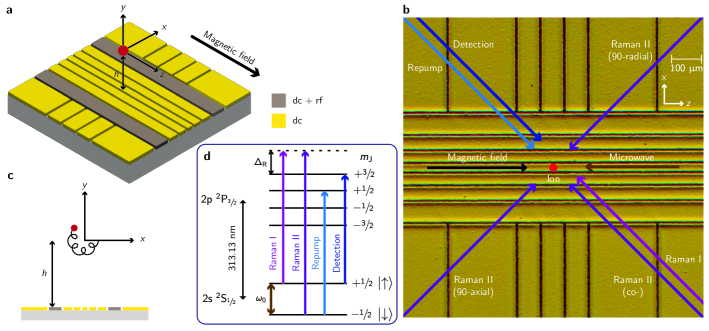
The experimental setup involves a single beryllium () ion confined using a static quadrupolar electric potential generated by applying voltages to the electrodes of a surface-electrode trap with geometry shown in (fig. 1 a-c). We use a radially symmetric potential , centred at a position m above the chip surface. The trap is embedded in a homogeneous magnetic field aligned along the -axis with a magnitude of T, supplied by a superconducting magnet. The trap assembly is placed in a cryogenic, ultra-high vacuum chamber which fits inside the magnet bore, with the aim of reducing background-gas collisions and motional heating. We load the trap by photo-ionization of beryllium atoms produced from either a resistively heated oven or an ablation source [34]. We regularly trap single ions for more than a day, with the primary loss mechanism being related to user interference. Further details about the apparatus can be found in the Supplementary Information.
The 3-d motion of an ion in a Penning trap can be described as a sum of three harmonic eigenmodes. The axial motion along is a simple harmonic oscillator at frequency . The radial motion is composed of modified-cyclotron () and magnetron () components, with frequencies where [35] and 5.12 MHz is the bare cyclotron frequency. Voltage control over the dc electrodes of the trap allows the axial frequency to be set to any value up to the stability limit, 3.62 MHz. This corresponds to a range MHz and MHz MHz for the magnetron and modified-cyclotron modes respectively. Doppler cooling of the magnetron mode, which has a negative total energy, is achieved using a weak axialization rf quadrupolar electric field ( 60 mV peak-to-peak voltage on the electrodes) at the bare cyclotron frequency, which resonantly couples the magnetron and modified-cyclotron motions [36, 37]. For the wiring configuration used in this work, the null of the rf field is produced at a height m above the electrode-plane. Aligning the null of the dc (trapping) field to the rf null is beneficial because it reduces driven radial motion at the axialization frequency; nevertheless, we find that Doppler cooling works with a relative displacement of tens of micrometres between the dc and rf nulls, albeit with lower efficiency. The rf field is required only during Doppler cooling, and not, for instance, during coherent operations on the spin or motion of the ion. All measurements in this work are taken at an axial frequency MHz, unless stated otherwise. The corresponding radial frequencies are MHz and MHz.
Fig. 1 d shows the electronic structure of the beryllium ion along with the transitions relevant to this work. We use an electron spin qubit (consisting of the and eigenstates within the ground-state manifold) which in the high field is almost decoupled from the nuclear spin. The qubit frequency is GHz. Doppler cooling is performed using the detection laser red-detuned from the (bright) cycling transition, while an additional repump laser optically pumps population from the (dark) level to the higher energy level via the fast-decaying excited state. State-dependent fluorescence with the detection laser allows for discrimination between the two qubit states based on photon counts collected on a photomultiplier tube using an imaging system which uses a 0.55 NA Schwarzschild objective. The fluorescence can also be sent to an electron-multiplying CCD (EMCCD) camera.
Coherent operations on the spin and motional degrees of freedom of the ion are performed either using stimulated Raman transitions with a pair of lasers tuned to GHz above the state, or using a microwave field. The former requires the use of two 313 nm lasers phase-locked at the qubit frequency which we achieve using the method outlined in reference [38]. By choosing different orientations of Raman laser paths, we can address the radial or axial motions, or implement single qubit rotations using a co-propagating Raman beam pair.
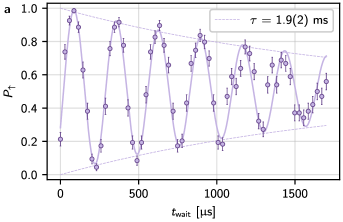
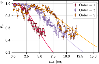
The qubit transition has a sensitivity of 28 GHz/T to the magnetic field, meaning the phase-coherence of our qubit is susceptible to temporal fluctuations or spatial gradients of the field across the extent of the ion’s motion. Using Ramsey spectroscopy, we measure a coherence time of 1.9(2) ms with the Raman beams. Similar values are measured with the microwave field, indicating that laser phase-noise from beam path fluctuations or imperfect phase-locking does not significantly contribute to dephasing. The nature of the noise appears to be slow on the timescale of a single experiment and the fringe contrast decay follows a Gaussian curve. We notice that the coherence is reduced if vibrations induced by the cryocoolers used to cool the magnet and the vacuum apparatus are not well decoupled from the experimental setup. Further characterization of the magnetic field noise is performed via applying different orders of the Uhrig dynamical decoupling sequence [39, 40], with resulting extracted coherence time from the measurements being 3.2(1) ms, 5.8(3) ms and 8.0(7) ms for orders 1, 3 and 5 respectively. Data on spin-dephasing is presented in the Supplementary Information.
A combination of the Doppler cooling and repump lasers prepares the ion in the electronic state and a thermal distribution of motional Fock states. After Doppler cooling using the axialization technique, we measure mean occupations of and via sideband spectroscopy on the first four red and blue sidebands [37].
Pulses of continuous sideband cooling [30, 37] are subsequently performed by alternatively driving the first and third blue (red) sidebands of a positive (negative) energy motional mode while simultaneously repumping the spin state to the bright state. The 3-d ground state can be prepared by applying this sequence for each of the three modes in succession. The use of the third sideband is motivated by the high Lamb-Dicke parameters of approximately 0.4 in our system [41, 42]. After a total time of 60 ms of cooling
we probe the temperature using sideband spectroscopy on the first blue and red sidebands [43]. Assuming thermal distributions, we measure . We have achieved similar performance of the ground-state cooling at all trap frequencies probed to date. The long duration of the sideband cooling sequence stems from the large (estimated as m) Gaussian beam radius of the Raman beams each with a power in the range 2 mW - 6 mW, leading to a Rabi frequency kHz, which corresponds to pi-times of approximately s, s and s for the ground state carrier, first and third sidebands respectively at MHz.
|
|
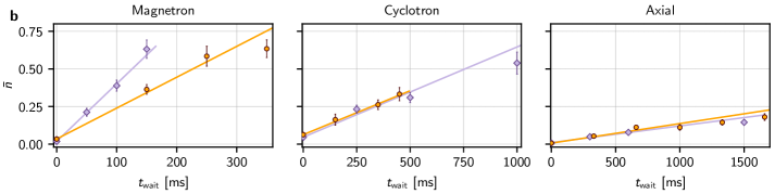
Trapped-ion quantum computing utilizes the collective motion of the ions for multi-qubit gates, and thus requires the motional degree of freedom to retain coherence over the timescale of the operation [44, 32]. One contribution to decoherence comes from motional heating due to fluctuations in the electric field at frequencies close to the oscillation frequencies of the ion. We measure this by inserting a variable-length delay between the end of sideband cooling and the temperature probe. As shown in figure 2, we observe motional heating rates . The corresponding electric-field spectral noise density for the axial mode, , is lower than any comparable measurement in a trap of similar size [45, 46]. As detailed in the Supplementary Information, we are able to trap ions in our setup with the trap electrodes detached from any external supply voltage except during Doppler cooling, which requires the axialization signal to pass to the trap. Using this method, we measure heating rates and for the axial and cyclotron modes respectively, while the rate for the lower-frequency magnetron mode drops to . This reduction suggests that external electrical noise contributes to the higher magnetron heating rate in the earlier measurements.
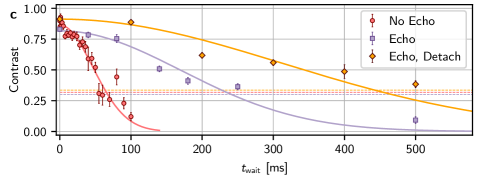
Motional state dephasing was measured using Ramsey spectroscopy, involving setting up a superposition of the first two Fock states of the axial mode (here MHz) using a combination of carrier and sideband pulses [47]. Following a variable wait time we reverse the preparation sequence with a shifted phase. The resulting decay of the Ramsey contrast shown in figure 2c is much faster than what would be expected from the heating rate. The decay is roughly Gaussian in form with a -coherence time of 66(5) ms. Inserting an echo pulse in the Ramsey sequence extends the coherence time to 240(20) ms, which indicates low-frequency noise components dominating the bare Ramsey coherence. Further improvement of the echo coherence time to 440(50) ms is observed when the trap electrodes are detached from external voltage sources between the conclusion of Doppler cooling and the start of the detection pulse, where again the axialization signal is beneficial. The data with the voltage sources detached is taken at MHz.
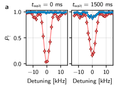
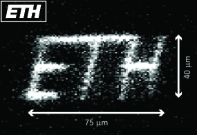
A critical component of the QCCD architecture [11] is ion transport. We demonstrate that the Penning trap approach allows us to perform this flexibly in two dimensions by adiabatically transporting a single ion. The ion is first Doppler cooled at the original location, and then transported in 4 ms to a second desired location. We then perform a detection pulse without applying axialization, and collect the ion fluorescence on an EMCCD camera. The exposure of the camera is limited to the time-window defined by the detection pulse. The lack of axialization is important when the ion is sufficiently far from the rf null in order to minimize radial excitation due to micromotion, and subsequently produce enough fluorescence during the detection window. The ion is then returned to the initial location. This procedure allows us to visualize the variety of positions to which we can shuttle the ion, as illustrated in Figure 3, where we have drawn out the first letters of the ETH Zürich logo. The image quality and maximum canvas size are only limited by the point-spread function and field of view of our imaging system, as well as the spatial extent of the detection laser beam, and not by any property of the transport. We have observed no evidence of motional excitation from transport that is significant compared to the natural heating expected over the duration of the transport.
This work marks a starting point for quantum computing and simulation in micro-scale Penning trap 2-d arrays. The major next steps are to operate with multiple sites of such an array, which will require optimization of the loading while keeping ions trapped in shallow potentials. This can be accomplished in the current trap with the appropriate wiring, but significant advantages could be gained by using a trap with a loading region and shuttling ions in to the micro-trap region. Increased spin coherence times could be achieved through improvements to mechanical stability of the magnet, or in the longer term through the use of decoherence-free-subspaces, which were envisioned in the original QCCD proposals [48, 11, 49]. For scaling to large numbers of sites, it is likely that scalable approaches to light delivery will be required, which might necessitate switching to an ion species which is more amenable to integrated optics [50, 51, 52, 53]. The use of advanced standard fabrication methods such as CMOS [54, 55] is facilitated compared to rf traps by the lack of high-voltage rf signals. Compatibility with these technologies demands an evaluation of how close to the surface ions could be operated for quantum computing and will require in-depth studies of heating - here an obvious next step is to sample electric field noise as a function of ion-electrode distance [46]. Unlike in rf traps, 3-d scans of electric field noise are possible in any Penning trap due to the flexibility of confinement from the uniform magnetic field. This flexibility of ion placement has advantages in many areas of ion trap physics, for instance in placing ions in anti-nodes of optical cavities [56], or sampling field noise from surfaces of interest [57, 58]. We therefore expect that our work will open new avenues in sensing, computation, simulation and networking, allowing ion trap physics to break out beyond its current constraints.
Acknowledgments
This project has received funding from ETH Zürich, the ERC under the EU’s Horizon 2020 research and innovation programme Grant agreement No. 818195, the EU Quantum Flagship H2020-FETFLAG-2018-03 (Grant Agreement No. 820495 AQTION), and the EU H2020 FET Open project PIEDMONS (Grant No. 801285). S. J. thanks Edgar Brucke for assistance in the cleanroom, and Joseba Alonso Otamendi for his involvements in work building up to the experiment assembly. T.S. thanks Peter Clements for designing the trap detachment PCB. A.B.-S. and C. O. thank the cleanroom staff in particular to T. Weimann, P. Hinze and O. Kerker and acknowledge funding from PTB, QUEST, LUH, and DFG through CRC 1227 DQ-mat, project A01. The authors express their gratitude towards Alfredo Ricci Vasquez and Matteo Simoni for careful reading and critical assessment of the manuscript.
Author Contributions
Data taking and analysis were performed by S. J., T. S. and P. H.. The apparatus was primarily built by T. S. and S. J. with contributions from P. H., C. T., C. A., R. O. and M. S.. The trap was fabricated by A. B-S. with input from C. O.. The manuscript was written by S. J., T. S., P. H and J. H. with input from all authors. The work was supervised by D. K. and J. H.
References
- Ballance et al. [2016] C. Ballance, T. Harty, N. Linke, M. Sepiol, and D. Lucas, High-fidelity quantum logic gates using trapped-ion hyperfine qubits, Physical Review Letters 117, 060504 (2016).
- Clark et al. [2021] C. R. Clark, H. N. Tinkey, B. C. Sawyer, A. M. Meier, K. A. Burkhardt, C. M. Seck, C. M. Shappert, N. D. Guise, C. E. Volin, S. D. Fallek, H. T. Hayden, W. G. Rellergert, and K. R. Brown, High-fidelity bell-state preparation with 40ca+ optical qubits, Physical Review Letters 127, 130505 (2021).
- Srinivas et al. [2021] R. Srinivas, S. C. Burd, H. M. Knaack, R. T. Sutherland, A. Kwiatkowski, S. Glancy, E. Knill, D. J. Wineland, D. Leibfried, A. C. Wilson, D. T. C. Allcock, and D. H. Slichter, High-fidelity laser-free universal control of trapped ion qubits, Nature 597, 209 (2021).
- Wang et al. [2021] P. Wang, C.-Y. Luan, M. Qiao, M. Um, J. Zhang, Y. Wang, X. Yuan, M. Gu, J. Zhang, and K. Kim, Single ion qubit with estimated coherence time exceeding one hour, Nature Communications 12, 233 (2021).
- Gidney and Ekerå [2021] C. Gidney and M. Ekerå, How to factor 2048 bit rsa integers in 8 hours using 20 million noisy qubits, Quantum 5, 433 (2021).
- Alexeev et al. [2021] Y. Alexeev, D. Bacon, K. R. Brown, R. Calderbank, L. D. Carr, F. T. Chong, B. DeMarco, D. Englund, E. Farhi, B. Fefferman, A. V. Gorshkov, A. Houck, J. Kim, S. Kimmel, M. Lange, S. Lloyd, M. D. Lukin, D. Maslov, P. Maunz, C. Monroe, J. Preskill, M. Roetteler, M. J. Savage, and J. Thompson, Quantum computer systems for scientific discovery, PRX Quantum 2, 017001 (2021).
- Pogorelov et al. [2021] I. Pogorelov, T. Feldker, C. D. Marciniak, L. Postler, G. Jacob, O. Krieglsteiner, V. Podlesnic, M. Meth, V. Negnevitsky, M. Stadler, B. Höfer, C. Wächter, K. Lakhmanskiy, R. Blatt, P. Schindler, and T. Monz, Compact ion-trap quantum computing demonstrator, PRX Quantum 2, 020343 (2021).
- Cetina et al. [2022] M. Cetina, L. Egan, C. Noel, M. Goldman, D. Biswas, A. Risinger, D. Zhu, and C. Monroe, Control of transverse motion for quantum gates on individually addressed atomic qubits, PRX Quantum 3, 010334 (2022).
- Kranzl et al. [2022] F. Kranzl, M. K. Joshi, C. Maier, T. Brydges, J. Franke, R. Blatt, and C. F. Roos, Controlling long ion strings for quantum simulation and precision measurements, Physical Review A 105, 052426 (2022).
- Pino et al. [2021] J. M. Pino, J. M. Dreiling, C. Figgatt, J. P. Gaebler, S. A. Moses, M. S. Allman, C. H. Baldwin, M. Foss-Feig, D. Hayes, K. Mayer, C. Ryan-Anderson, and B. Neyenhuis, Demonstration of the trapped-ion quantum ccd computer architecture, Nature 592, 209 (2021).
- Kielpinski et al. [2002] D. Kielpinski, C. Monroe, and D. J. Wineland, Architecture for a large-scale ion-trap quantum computer, Nature 417, 709 (2002).
- Home et al. [2009] J. P. Home, D. Hanneke, J. D. Jost, J. M. Amini, D. Leibfried, and D. J. Wineland, Complete Methods Set for Scalable Ion Trap Quantum Information Processing, Science 325, 1227 (2009).
- Ryan-Anderson et al. [2021] C. Ryan-Anderson, J. Bohnet, K. Lee, D. Gresh, A. Hankin, J. Gaebler, D. Francois, A. Chernoguzov, D. Lucchetti, N. Brown, T. Gatterman, S. Halit, K. Gilmore, J. Gerber, B. Neyenhuis, D. Hayes, and R. Stutz, Realization of real-time fault-tolerant quantum error correction, Physical Review X 11, 041058 (2021).
- Zhang et al. [2022] C. Zhang, K. K. Mehta, and J. P. Home, Optimization and implementation of a surface-electrode ion trap junction, New Journal of Physics 24, 073030 (2022).
- Blakestad et al. [2009] R. B. Blakestad, C. Ospelkaus, A. P. VanDevender, J. M. Amini, J. Britton, D. Leibfried, and D. J. Wineland, High-fidelity transport of trapped-ion qubits through an x-junction trap array, Physical Review Letters 102, 153002 (2009).
- Moehring et al. [2011] D. L. Moehring, C. Highstrete, D. Stick, K. M. Fortier, R. Haltli, C. Tigges, and M. G. Blain, Design, fabrication and experimental demonstration of junction surface ion traps, New Journal of Physics 13, 75018 (2011).
- Shu et al. [2014] G. Shu, G. Vittorini, A. Buikema, C. S. Nichols, C. Volin, D. Stick, and K. R. Brown, Heating rates and ion-motion control in a y-junction surface-electrode trap, Physical Review A 89, 062308 (2014).
- Burton et al. [2023] W. C. Burton, B. Estey, I. M. Hoffman, A. R. Perry, C. Volin, and G. Price, Transport of multispecies ion crystals through a junction in a radio-frequency paul trap, Physical Review Letters 130, 173202 (2023).
- Palani et al. [2023] D. Palani, F. Hasse, P. Kiefer, F. Boeckling, J.-P. Schroeder, U. Warring, and T. Schaetz, High-fidelity transport of trapped-ion qubits in a multilayer array, Physical Review A 107, L050601 (2023).
- Berkeland et al. [1998] D. J. Berkeland, J. D. Miller, J. C. Bergquist, W. M. Itano, and D. J. Wineland, Minimization of ion micromotion in a Paul trap, Journal of Applied Physics 83, 5025 (1998).
- Jain et al. [2020] S. Jain, J. Alonso, M. Grau, and J. Home, Scalable arrays of micro-penning traps for quantum computing and simulation, Physical Review X 10, 031027 (2020).
- Malinowski et al. [2023] M. Malinowski, D. T. C. Allcock, and C. J. Ballance, How to wire a 1000-qubit trapped ion quantum computer (2023), arXiv:2305.12773 .
- Hellwig et al. [2010] M. Hellwig, A. Bautista-Salvador, K. Singer, G. Werth, and F. Schmidt-Kaler, Fabrication of a planar micro penning trap and numerical investigations of versatile ion positioning protocols, New Journal of Physics 12, 065019 (2010).
- Ahmadi et al. [2017] M. Ahmadi, B. X. R. Alves, C. J. Baker, W. Bertsche, E. Butler, A. Capra, C. Carruth, C. L. Cesar, M. Charlton, S. Cohen, R. Collister, S. Eriksson, A. Evans, N. Evetts, J. Fajans, T. Friesen, M. C. Fujiwara, D. R. Gill, A. Gutierrez, J. S. Hangst, W. N. Hardy, M. E. Hayden, C. A. Isaac, A. Ishida, M. A. Johnson, S. A. Jones, S. Jonsell, L. Kurchaninov, N. Madsen, M. Mathers, D. Maxwell, J. T. K. McKenna, S. Menary, J. M. Michan, T. Momose, J. J. Munich, P. Nolan, K. Olchanski, A. Olin, P. Pusa, C. Ø. Rasmussen, F. Robicheaux, R. L. Sacramento, M. Sameed, E. Sarid, D. M. Silveira, S. Stracka, G. Stutter, C. So, T. D. Tharp, J. E. Thompson, R. I. Thompson, D. P. van der Werf, and J. S. Wurtele, Observation of the 1s–2s transition in trapped antihydrogen, Nature 541, 506 (2017).
- Ulmer et al. [2015] S. Ulmer, C. Smorra, A. Mooser, K. Franke, H. Nagahama, G. Schneider, T. Higuchi, S. V. Gorp, K. Blaum, Y. Matsuda, W. Quint, J. Walz, and Y. Yamazaki, High-precision comparison of the antiproton-to-proton charge-to-mass ratio, Nature 524, 196 (2015).
- Hanneke et al. [2008] D. Hanneke, S. Fogwell, and G. Gabrielse, New Measurement of the Electron Magnetic Moment and the Fine Structure Constant, Physical Review Letters 100, 120801 (2008), arXiv:0801.1134 .
- DiSciacca and Gabrielse [2012] J. DiSciacca and G. Gabrielse, Direct Measurement of the Proton Magnetic Moment, Physical Review Letters 108, 153001 (2012).
- Britton et al. [2012] J. W. Britton, B. C. Sawyer, A. C. Keith, C.-C. J. Wang, J. K. Freericks, H. Uys, M. J. Biercuk, and J. J. Bollinger, Engineered two-dimensional ising interactions in a trapped-ion quantum simulator with hundreds of spins, Nature 484, 489 (2012).
- Bohnet et al. [2016] J. G. Bohnet, B. C. Sawyer, J. W. Britton, M. L. Wall, A. M. Rey, M. Foss-Feig, and J. J. Bollinger, Quantum spin dynamics and entanglement generation with hundreds of trapped ions, Science 352, 1297 (2016).
- Stutter et al. [2018] G. Stutter, P. Hrmo, V. Jarlaud, M. K. Joshi, J. F. Goodwin, and R. C. Thompson, Sideband cooling of small ion coulomb crystals in a penning trap, Journal of Modern Optics 65, 549 (2018).
- Stahl et al. [2005] S. Stahl, F. Galve, J. Alonso, S. Djekic, W. Quint, T. Valenzuela, J. Verdu, M. Vogel, and G. Werth, A planar Penning trap, The European Physical Journal D 32, 139 (2005).
- Leibfried et al. [2003] D. Leibfried, B. DeMarco, V. Meyer, D. Lucas, M. Barrett, J. Britton, W. M. Itano, B. Jelenković, C. Langer, T. Rosenband, and D. J. Wineland, Experimental demonstration of a robust, high-fidelity geometric two ion-qubit phase gate, Nature 422, 412 (2003).
- Wilson et al. [2014] A. C. Wilson, Y. Colombe, K. R. Brown, E. Knill, D. Leibfried, and D. J. Wineland, Tunable spin–spin interactions and entanglement of ions in separate potential wells, Nature 512, 57 (2014).
- Lo et al. [2014] H.-Y. Lo, J. Alonso, D. Kienzler, B. C. Keitch, L. E. de Clercq, V. Negnevitsky, and J. P. Home, All-solid-state continuous-wave laser systems for ionization, cooling and quantum state manipulation of beryllium ions, Applied Physics B 114, 17 (2014), arXiv:1306.3780 .
- Brown and Gabrielse [1986] L. S. Brown and G. Gabrielse, Geonium theory: Physics of a single electron or ion in a penning trap, Reviews of Modern Physics 58, 233 (1986).
- Powell et al. [2002] H. F. Powell, D. M. Segal, and R. C. Thompson, Axialization of laser cooled magnesium ions in a penning trap, Physical Review Letters 89, 093003 (2002).
- Hrmo et al. [2019] P. Hrmo, M. K. Joshi, V. Jarlaud, O. Corfield, and R. C. Thompson, Sideband cooling of the radial modes of motion of a single ion in a penning trap, Physical Review A 100, 043414 (2019).
- Mielke et al. [2021] J. Mielke, J. Pick, J. A. Coenders, T. Meiners, M. Niemann, J. M. Cornejo, S. Ulmer, and C. Ospelkaus, 139 ghz uv phase-locked raman laser system for thermometry and sideband cooling of 9be+ ions in a penning trap, Journal of Physics B: Atomic, Molecular and Optical Physics 54, 195402 (2021).
- Uhrig [2007] G. S. Uhrig, Keeping a quantum bit alive by optimized -pulse sequences, Physical Review Letters 98, 100504 (2007).
- Biercuk et al. [2009] M. J. Biercuk, H. Uys, A. P. VanDevender, N. Shiga, W. M. Itano, and J. J. Bollinger, Optimized dynamical decoupling in a model quantum memory, Nature 458, 996 (2009).
- Chen et al. [2017] J. S. Chen, S. M. Brewer, C. W. Chou, D. J. Wineland, D. R. Leibrandt, and D. B. Hume, Sympathetic Ground State Cooling and Time-Dilation Shifts in an Al 27 + Optical Clock, Physical Review Letters 118, 1 (2017), arXiv:1608.05047 .
- Joshi et al. [2019] M. K. Joshi, P. Hrmo, V. Jarlaud, F. Oehl, and R. C. Thompson, Population dynamics in sideband cooling of trapped ions outside the lamb-dicke regime, Physical Review A 99, 013423 (2019).
- Monroe et al. [1995] C. Monroe, D. M. Meekhof, B. E. King, S. R. Jefferts, W. M. Itano, D. J. Wineland, and P. Gould, Resolved-Sideband Raman Cooling of a Bound Atom to the 3D Zero-Point Energy, Physical Review Letters 75, 4011 (1995).
- Sørensen and Mølmer [2000] A. Sørensen and K. Mølmer, Entanglement and quantum computation with ions in thermal motion, Physical Review A 62, 022311 (2000).
- Lakhmanskiy et al. [2019] K. Lakhmanskiy, P. C. Holz, D. Schärtl, B. Ames, R. Assouly, T. Monz, Y. Colombe, and R. Blatt, Observation of superconductivity and surface noise using a single trapped ion as a field probe, Physical Review A 99, 023405 (2019).
- Brownnutt et al. [2015] M. Brownnutt, M. Kumph, P. Rabl, and R. Blatt, Ion-trap measurements of electric-field noise near surfaces, Reviews of Modern Physics 87, 1419 (2015).
- Turchette et al. [2000] Q. A. Turchette, C. J. Myatt, B. E. King, C. A. Sackett, D. Kielpinski, W. M. Itano, C. Monroe, and D. J. Wineland, Decoherence and decay of motional quantum states of a trapped atom coupled to engineered reservoirs, Physical Review A 62, 053807 (2000).
- Wineland et al. [1998] D. Wineland, C. Monroe, W. Itano, D. Leibfried, B. King, and D. Meekhof, Experimental issues in coherent quantum-state manipulation of trapped atomic ions, Journal of Research of the National Institute of Standards and Technology 103, 259 (1998).
- Cirac and Zoller [2000] J. I. Cirac and P. Zoller, A scalable quantum computer with ions in an array of microtraps, Nature 404, 579 (2000).
- Mehta et al. [2020] K. K. Mehta, C. Zhang, M. Malinowski, T.-L. Nguyen, M. Stadler, and J. P. Home, Integrated optical multi-ion quantum logic, Nature 586, 533 (2020), arxiv:2002.02258 .
- Mehta et al. [2016] K. K. Mehta, C. D. Bruzewicz, R. McConnell, R. J. Ram, J. M. Sage, and J. Chiaverini, Integrated optical addressing of an ion qubit, Nature Nanotechnology 11, 1066 (2016).
- Niffenegger et al. [2020] R. J. Niffenegger, J. Stuart, C. Sorace-Agaskar, D. Kharas, S. Bramhavar, C. D. Bruzewicz, W. Loh, R. T. Maxson, R. McConnell, D. Reens, G. N. West, J. M. Sage, and J. Chiaverini, Integrated multi-wavelength control of an ion qubit, Nature 586, 538 (2020).
- Ivory et al. [2021] M. Ivory, W. J. Setzer, N. Karl, H. McGuinness, C. DeRose, M. Blain, D. Stick, M. Gehl, and L. P. Parazzoli, Integrated Optical Addressing of a Trapped Ytterbium Ion, Physical Review X 11, 041033 (2021).
- Mehta et al. [2014] K. K. Mehta, A. M. Eltony, C. D. Bruzewicz, I. L. Chuang, R. J. Ram, J. M. Sage, and J. Chiaverini, Ion traps fabricated in a CMOS foundry, Applied Physics Letters 105, 044103 (2014).
- Auchter et al. [2022] S. Auchter, C. Axline, C. Decaroli, M. Valentini, L. Purwin, R. Oswald, R. Matt, E. Aschauer, Y. Colombe, P. Holz, T. Monz, R. Blatt, P. Schindler, C. Rössler, and J. Home, Industrially microfabricated ion trap with 1 eV trap depth, Quantum Science and Technology 7, 035015 (2022).
- Schupp et al. [2021] J. Schupp, V. Krcmarsky, V. Krutyanskiy, M. Meraner, T. Northup, and B. Lanyon, Interface between trapped-ion qubits and traveling photons with close-to-optimal efficiency, PRX Quantum 2, 020331 (2021).
- Hite et al. [2021] D. A. Hite, K. S. McKay, and D. P. Pappas, Surface science motivated by heating of trapped ions from the quantum ground state, New Journal of Physics 23, 103028 (2021).
- McKay et al. [2021] K. S. McKay, D. A. Hite, P. D. Kent, S. Kotler, D. Leibfried, D. H. Slichter, A. C. Wilson, and D. P. Pappas, Measurement of electric-field noise from interchangeable samples with a trapped-ion sensor, Physical Review A 104, 052610 (2021).
- Tao et al. [2018] J. Tao, N. P. Chew, L. Guidoni, Y. D. Lim, P. Zhao, and C. S. Tan, Fabrication and characterization of surface electrode ion trap for quantum computing (IEEE, 2018) pp. 363–366.
- Chiaverini et al. [2005] J. Chiaverini, R. Blakestad, J. Britton, J. Jost, C. Langer, D. Leibfried, R. Ozeri, and D. Wineland, Surface-electrode architecture for ion-trap quantum information processing, Quantum Information and Computation 5, 419 (2005).
- Bautista-Salvador et al. [2019] A. Bautista-Salvador, G. Zarantonello, H. Hahn, A. Preciado-Grijalva, J. Morgner, M. Wahnschaffe, and C. Ospelkaus, Multilayer ion trap technology for scalable quantum computing and quantum simulation, New Journal of Physics 21, 043011 (2019).
- Stuart et al. [2019] J. Stuart, R. Panock, C. Bruzewicz, J. Sedlacek, R. McConnell, I. Chuang, J. Sage, and J. Chiaverini, Chip-integrated voltage sources for control of trapped ions, Phys. Rev. Appl. 11, 024010 (2019).
Supplementary Information
Spin-Coherence Data
The data for spin-dephasing measurements can be found in figure S1.
|
|
Trap design and fabrication
The design of our surface-electrode Penning trap is based on the traditional 4-wire or 5-wire traps widely used in the rf trapped-ion community [59, 60]. Two configurations of arranging ions were envisaged during the design phase - a) a single trapping site that can be placed at a variable height above the surface, and b) two trap sites separated along the in-plane radial axis. In total the trap consists of 25 electrodes laid out on a planar surface and surrounded by a conducting ground plane. All electrodes are supplied with static voltages, while an individual rf signal can be applied to each of the middle 7 electrodes running parallel to the magnetic field, such that they also potentially serve as axialization electrodes - see fig. 1 b in the main text. The static voltages applied to the electrodes allow us to control the elements of the Hessian matrix of the trapping potential. While typical rf traps might use two or three rf electrodes, the extra rf electrodes on our trap allow us to provide two nodal lines with variable separation in the rf axialization potential, or to produce a node at a variable height above the chip surface. Experiments included in this article have been restricted to ions in a single trap site m above the trap surface, with only the outermost rf electrodes used for axialization. This height is determined using an analytical calculation and confirmed via an independent simulation based on the boundary element method.
The trap was fabricated at PTB, Braunschweig, using a single layer processing method [61] depositing gold electrodes via electroplating on a sapphire substrate. The process yields an electrode thickness in the range m to m and approximately m-wide gaps between the electrodes, which provides excellent electrical shielding of the substrate.
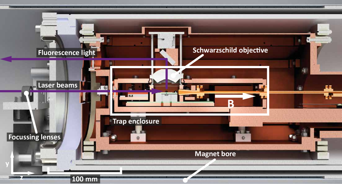
Cryogenic vacuum apparatus
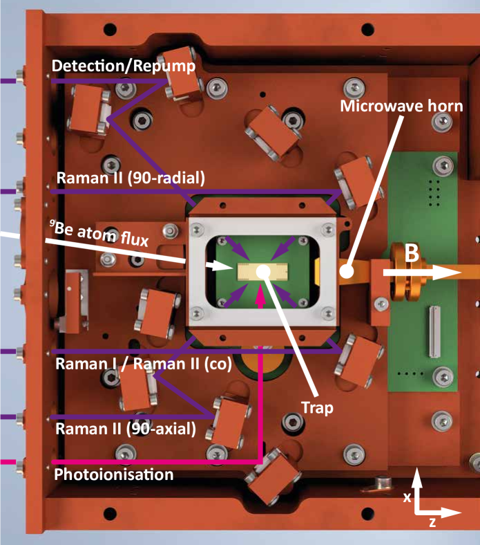
The trap is placed in a cryogenic vacuum apparatus which is inserted into the horizontal magnet bore (fig. S2). The trap enclosure (fig. S3) is surrounded by a vacuum chamber and heat shields, and is held at a temperature of . Laser beams for photoionization, Doppler cooling, repumping, state detection and stimulated Raman transitions are delivered along the magnet bore through a vacuum viewport and are directed across the trap by mirrors mounted within the cryogenic trap enclosure.
The detection laser beam is delivered at an angle of with respect to the magnetic field, such that it has an overlap with all the motional mode eigenvectors. Three configurations of the Raman beams are possible. The Raman I + Raman II (co) beams are co-propagating and produce a negligible wavevector difference, which causes negligible coupling to the motional modes, The other two beam pairs, Raman I + Raman II (90-axial) and Raman I + Raman II (90-radial) have wavevector differences along the axial and the radial motional modes respectively. Fluorescence from the ion is collected by a Schwarzschild objective and directed down the bore of the magnet by a further mirror. Microwave radiation is delivered through a hollow WR-10 waveguide and directed across the trap using a horn antenna. An effusive oven is placed on the room temperature stage of the apparatus and generates a flux of neutral atoms, which is directed at the centre of the trap chip.
Ultra-high vacuum at the trap is achieved by cryopumping. Additionally, an activated charcoal getter is added within the trap enclosure to improve the helium partial pressure. Vacuum levels in the room temperature stage of the apparatus are measured to be . While we cannot directly measure the vacuum pressure within the trap enclosure, we routinely keep ions for several days with primary loss mechanisms related to equipment malfunction or user error, indicating excellent vacuum.
Voltage-Source Detachment
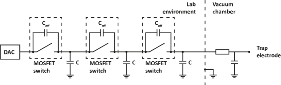
As confinement of an ion in a Penning trap requires only static electric and magnetic fields, it is possible to temporarily detach the trap electrodes from the voltage sources external to the Faraday cage formed by the vacuum chamber. In every line connecting a trap electrode to a digital-to-analog converter (DAC) and the lab environment, we place switches which can be actuated using a digital signal (fig. S4). In our experimental sequence, we detach the trap after Doppler cooling, which requires the axialization drive to pass to the trap.
The combined capacitance of the trap electrode and the in-vacuum RC filter will retain the voltage that was applied by the DAC before isolating the trap. Although discharging is observed over timescales of minutes, we find no measurable change of ion position or motional mode frequencies during up to of trap detachment.
To reach maximal isolation from noise present in the lab environment, we concatenate three MOSFET-based switches. The capacitor acts as a capacitive divider together with the switch capacitance to increase isolation performance over the full range of possible motional mode frequencies (dc - ). Simulating this circuit and including parasitic capacitances yields an estimated isolation of 83 dB at dc and 77 dB at .
The option to entirely isolate the trap from the lab environment during parts of the experimental sequence is exclusive to Penning traps. It may permit reduced filtering requirements, in turn enabling faster ion transport, while still allowing low noise levels when the ions are kept at static positions [62]. It may simplify the task of eliminating external noise sources that are hard to find, or hard to remove.