Accurate Eye Tracking from Dense 3D Surface Reconstructions using Single-Shot Deflectometry
Abstract
Eye-tracking plays a crucial role in the development of virtual reality devices, neuroscience research, and psychology. Despite its significance in numerous applications, achieving an accurate, robust, and fast eye-tracking solution remains a considerable challenge for current state-of-the-art methods. While existing reflection-based techniques (e.g., "glint tracking") are considered the most accurate, their performance is limited by their reliance on sparse 3D surface data acquired solely from the cornea surface.
In this paper, we rethink the way how specular reflections can be used for eye tracking: We propose a novel method for accurate and fast evaluation of the gaze direction that exploits teachings from single-shot phase-measuring-deflectometry (PMD). In contrast to state-of-the-art reflection-based methods, our method acquires dense 3D surface information of both cornea and sclera within only one single camera frame (single-shot). Improvements in acquired reflection surface points (“glints”) of factors are easily achievable. We show the feasibility of our approach with experimentally evaluated gaze errors of only , demonstrating a significant improvement over the current state-of-the-art.
1 Introduction
Eye tracking is an enabling technology that is widely involved in different fields of application. In virtual/augmented reality (VR/AR), it enables important functions, such as foveated rendering, compensation of the vergence-accommodation conflict, or interactions with the user interface virtual avatars[1]. In clinical applications, it helps with the diagnosis of disorders [2], or facilitates improved surgical training[3]. Moreover, eye tracking is frequently used in psychology research [4] and cognitive neuroscience [5]. Many of the applications mentioned above utilize commercially available eye-trackers. Although the reported error metrics for these devices vary, their best reported error margin mostly lies in the range [1]. While this number sounds impressive at first glance, it still leaves room for improvement for some applications. For example, as VR/AR headsets might reach the targeted “retinal resolution” in the future [6], a error would correspond to pix, which could still pose challenges when the navigation through the user interface should happen purely gaze-based with “mouse precision”. At larger standoff distances of e.g. , a gazing error leads to a lateral localization error of , which is already too large, e.g., to exactly determine a focused product in a supermarket shelf or to interact with a virtual avatar in a larger crowd.
Current state-of-the-art optical eye tracking approaches can be divided into two groups: image-based methods [7, 8, 9, 10, 11] and reflection-based methods[12, 13, 14, 15, 16, 17]. Image-based methods detect features such as the pupil, iris, veins, or limbus in 2D images of the eye and use them to estimate the gaze direction. This can be done, e.g., by exploiting geometrical relations in the captured eye image (iris center, pupil eccentricity, etc.)[10, 9, 18, 8], or via deep learning[11, 19, 20, 21]. The density of 2D image features is, however, relatively sparse for all cases, which potentially limits the quality of the reconstruction. Moreover, the transparent property of the cornea makes it difficult for image-based methods to extract accurate features in these regions (e.g., from the underlying iris) since the refraction of light at the cornea surface is different at different viewing angles[22].
In contrast, state-of-the-art reflection-based methods directly or indirectly measure the 3D coordinates of the cornea surface and use the respective information to calculate the gaze. ’Glint tracking’ is the most prominent method in this class[16, 12, 23, 14]: Around 2-12 infrared point light sources are spatially arranged in front of the eye (e.g., in a circle) to be reflected by the cornea surface. Combined with other measured 2D features, such as the pupil center, the gaze direction can be estimated. For those methods, it can be intuitively understood that more acquired 3D surface information about the eye generally leads to higher gaze reconstruction accuracy [14]. However, current methods do not acquire more than sparse surface points. This relatively low number of data points is caused by the conceptual design of the respective glint tracking method: Its susceptibility to ambiguities makes it difficult to increase the number of point sources.
In this paper, we improve the accuracy of reflection-based eye tracking by radically increasing the number of measured eye surface points from to over . We pair this significant increase in acquired information with novel sophisticated algorithms that calculate the gaze direction fast and computationally efficient. Our method to acquire 3D information about the eye surface is based on phase measuring deflectometry (PMD)[24]. PMD was originally invented as an optical metrology method for the dense 3D reconstruction of specular objects, like lenses or astronomical mirrors [25, 26, 27, 28, 29]. Modern well-calibrated PMD setups can reach sub-micron accuracy using only inexpensive off-the-shelf equipment (display and camera)[24, 27, 30, 31]. For that reason, PMD is well known in the metrology community as the big competitor to highly accurate optical interferometry systems. Recently PMD has been used, e.g., for cultural heritage analysis[32, 33], or to measure the topography of the human cornea[34] for medical diagnosis. Its special design for specular surfaces makes PMD an ideal technique for eye surface measurements which yields several advantages compared to techniques designed to measure matte surfaces, such as fringe projection profilometry[35].
In a PMD setup, an off-the-shelf display showing a sinusoidal pattern serves as the illumination source. The reflection of the display pattern over the object surface is observed with a camera. Each pixel on the display can be seen as an independent single-point light source that can be used to acquire information about a surface point. For example, a fairly "low resolution" display paired with a "low resolution" camera can, in theory, already acquire independent 3D surface points. Although these very high numbers are not achievable in practice due to geometrical constraints, our prototype setup experimentally demonstrates measurements with more than 40,000 acquired surface points. Compared to glint tracking with 12 points light sources, this is an improvement in acquired surface points of , which results in experimentally evaluated gaze errors between and at a precision below (see Tab 1).
Besides accuracy and precision, another important factor in eye tracking is speed. Standard PMD principles normally rely on temporal phase shifting, which requires a temporal sequence of multiple camera images to calculate a single 3D view [36]. For fast object movements (like those of human eyes), such a temporal phase-shifting procedure is commonly not motion-robust and would lead to motion artifacts in the final result. For this reason, we exploit a method to measure the complete 3D information about the human eye in single-shot. Our implemented approach is based on 2D continuous wavelet transforms for phase measurement [37]. Due to its single-shot character, it allows for fully motion-robust measurements, regardless of the moving speed of the eye. We summarize the contributions of our paper as follows:
-
•
We introduce a new reflection-based method for eye tracking that is fast, accurate, and precise. Our method exploits dense 3D surface information of the eye (such as surface shape and normals) to estimate the gaze. It does not rely on secondary eye features (such as pupil diameter or veins) and does not require a rendered "eye base model".
-
•
We develop a novel eye-tracking prototype setup based on single-shot stereo deflectometry [37] to capture dense and precise surface information within each camera frame. To the best of our knowledge, this is the first time that deflectometry has been used for eye tracking.
-
•
We introduce a novel calibration approach for our prototype system. The approach stands out by its flexibility and ease of use. Its potential to improve other deflectometry systems goes far beyond the application scope of this paper.
-
•
We demonstrate the feasibility of our approach with quantitative evaluations of real experiments and simulations. Our experiments showcase evaluated gaze errors with a precision of the calculated gaze . These results demonstrate a significant improvement over the current state of the art.
2 Methods
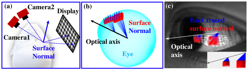
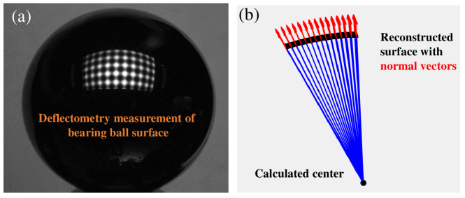
Our proposed eye-tracking method leverages accurate and dense 3D measurements of the eye surface. We employ a specifically tailored deflectometry setup to measure the shape and normal map of the eye surface: Instead of using sparse point lights ("glints"), we illuminate the eye with an extended display. Each pixel on the display serves as an individual point light source, and the observed reflection of the display over the eye surface covers both the cornea and sclera region of the eye (see Fig.1). To solve the inherent normal-depth ambiguity[24] and to further enlarge the measured surface area (see Fig.1), we implement a second camera ("stereo-deflectometry").
To facilitate the potential for low latency measurements, we use a single-shot deflectometry approach that exploits one single cross-sinusoid pattern (Fig.1.(a) and (c)) rather than classical phase-shifting deflectometry that requires multiple sequentially captured patterns. After retrieving the depth map and normal map of the eye surface, we calculate the gaze direction as follows: Given the assumption that the shape of the cornea and sclera can be represented by two spherical surfaces with different radii, one can back-trace the measured surface normals towards the center of the eye where they aggregate at two points: The center of the cornea sphere and the center of the sclera sphere. The gazing vector is the vector that connects these two points (see Fig.1.(b) and (c)).
In the following, we will provide a detailed explanation of our applied procedures outlined above. We will start with classical phase-shifting deflectometry and single-shot deflectometry, followed by our method for iterative eye surface reconstruction(section 2.1) and gaze estimation (section 2.2). Eventually, we will introduce a novel system calibration method that significantly improves the quality of our measurements and simplifies the calibration process (section 2.3).
2.1 Deflectometry: Sequential captures vs Single-shot
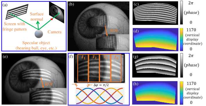
Deflectometry is an established reflection-based method to reconstruct the surface of specular objects. In a classical deflectometry setup (Fig.2.(a)), a camera observes a display over the specular object surface. Depending on the shape of the object surface, the image of the known display pattern is deformed in the camera image. From this deformation, 3D information about the object can be calculated. The deformation of the pattern is commonly quantified by identifying so-called corresponding points between the display image and the camera image. Eventually, rays are traced between a display pixel and its corresponding camera pixel to calculate the surface normals (and later the shape via integration). As each display pixel emits light in all directions, one single pair of corresponding points leads to many possible combinations of surface normal and surface height. A common solution to this “depth-normal ambiguity problem”[36] is to add a second camera and turn the system into a “stereo deflectometry” system[24].
A crucial step in the deflectometry process is to obtain the correspondence between the display and camera pixels. The common procedure is to encode the display pixel positions in a pattern, and eventually decode them on the camera chip by analyzing the pattern. This is commonly done over the phase of displayed sinusoidal intensity patterns of known frequency.
2.1.1 Correspondence evaluation in classical phase measuring deflectometry (PMD)
In PMD, the phase values for correspondence evaluation are obtained by temporally shifting vertical and horizontal sinusoidal patterns on the display. Patterns with horizontal stripes (as shown in Fig. 2.(e)) encode the vertical display coordinate , while patterns with vertical stripes encode the horizontal display coordinate . The reflection of the pattern over the object surface is imaged with the camera. The intensity in each camera pixel can be expressed as
| (1) |
and are terms that contain information about the unknown reflectivity of the respective surface point, the bias illumination, and the unknown background illumination at this point. is the vertical phase value that is needed to establish correspondence. In classical PMD, is retrieved via temporal phase shifting, e.g., by sequentially changing to and acquiring an image for each of those phase shifts (“four-phaseshift-method") (see Fig. 2.(e) and (f)) [24, 36]. Eventually, is calculated by
| (2) |
Figure 2.(g) shows the retrieved vertical phase map in the camera image, which uniquely encodes the corresponding vertical display coordinates (Fig.2.(h)) after unwrapping. The horizontal phase map and the horizontal display coordinates are retrieved in an analog fashion by phase-shifting vertical sinusoidal patterns. Eventually, the surface normal is calculated from the obtained correspondence between display pixels and camera pixels via ray tracing (see Fig. 2.(a)), where height-normal ambiguities are resolved by exploiting information from the second camera, as described in sec. 2.1.3.
Multi-phase shift procedures like the discussed four-phaseshift-method provide high-quality results but have one severe drawback for the purpose of this paper: Several sequentially captured camera images (8 in this example) are required to capture one single 3D model. During this sequence, the object is not allowed to move. As the human eye is in constant fast motion, this method is not feasible for our purpose in practice. For this reason, we utilize a procedure to facilitate high-quality deflectometry measurements in single-shot.
2.1.2 Correspondence evaluation via single-shot deflectometry
To obtain the display-camera correspondence information in single-shot, the unidirectional sinusoidal pattern on the display is replaced with a crossed sinusoidal pattern, i.e., one sinusoid in the horizontal direction, overlaid with a sinusoid in vertical direction (see Fig. 2.(b) or pattern schematic in Fig. 1.(a)). In analogy to Eq. 1, the intensity in each camera pixel can be expressed by the term
| (3) |
which now contains both the horizontal and vertical phase values , , needed to establish correspondence. A common method to retrieve these phase values in single-shot exploits single-sideband demodulation in Fourier space[38, 39, 34, 40]. However, as the frequency evaluation with a Fourier transform is a global operation, the respective method suffers limitations of the allowed maximal object bandwidth. A violation of these limitations leads to artifacts in the reconstruction. In our case, these artifacts are caused by the high surface frequencies at the limbus region of the eye. For this reason, we apply a recent method to locally retrieve the phase value in single-shot [37]. The approach is based on 2D continuous wavelet transforms, and is able to locally evaluate the phase of the crossed fringe pattern. This works by convolving the camera image with a morlet wavelet that can be varied in scale and translation:
| (4) |
Here is the scale parameter, are the translation parameters in both directions, is the center frequency of the wavelet and is the bandwidth. As the object shape does not only influence the local frequency of the pattern in the camera image, but also its direction, the wavelet additionally needs to be rotated to find the maximal wavelet modules:
| (5) |
Eventually, the horizontal phase value is determined by the phase angle of the complex valued wavelet transform. For the vertical phase value , the wavelet is rotated by and the process is repeated. The retrieved vertical phase map is shown in Fig.2(c) and the respective correspondence map is shown in Fig.2(d).
2.1.3 Surface normal and shape reconstruction
After the correspondence between camera image and display has been obtained, the eye surface can be reconstructed. As shown in Fig. 2.(a), the surface normal can be obtained by tracing rays between two corresponding points over the specular object surface. However, this mapping is not unique. If the object surface changes its distance to the camera along the ray of sight, the same pair of corresponding points would lead to a different surface normal. This problem is commonly referred to as the ‘depth-normal-ambiguity problem’ [36]. We solve this problem by exploiting information from a second camera that is added to the system (“stereo deflectometry”) [24]. The basic idea: Each camera has its own set of possible surface normal-height combinations, but both sets only match for one combination, which is the true height and normal of the surface.
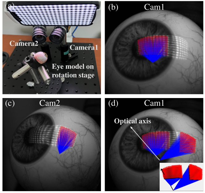
Calculating every single surface point via stereo deflectometry is computationally expensive, which could restrict the potential future real-time implementation of our system. Moreover, only those surface points can be reconstructed that reflect a display pixel back in both cameras, which limits the effective coverage (the total surface area that can be measured) of the method. To speed up the reconstruction and increase the effective coverage, we only use stereo deflectometry to reconstruct surface normal and height at a few sparse "anchor points" of the surface. Eventually, we obtain a dense surface reconstruction by iterative slope integration [41]: A first estimate of the surface height map is initialized as best fit surface through all anchor points. We calculate the first iteration of the surface normal map “with respect to” this initial surface height map. This means that the normal in each pixel is calculated by using the respective height value of the initial surface height map. Eventually, the next iteration of the surface height map is calculated by integrating the calculated normal map via zonal reconstruction (see Supplementary Material and [42] for more information). A second iteration of the normal map is then calculated with respect to the updated height map, and so on. This process is repeated until the calculated iterations of surface height map and normal map converge, which typically happens after 2-3 iterations. The result is a highly accurate representation of the measured eye surface (including surface normals), which only requires minimal overlap of measured surface points between both cameras. For example, the cornea surface can be reconstructed from camera 1, while the sclera surface can be reconstructed from camera 2 (see Fig.6.(b)(d)).
2.2 Gaze estimation
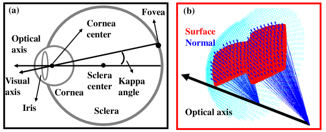
The gaze direction is estimated from the obtained dense eye surface 3D reconstruction. Our calculation is based on the common assumption that cornea and sclera can be approximated by two spheres with different radii (see Fig.3.(b))[16, 15, 43, 44]. The cornea center, sclera center, and pupil center are located on the optical axis of the eye. In each camera pixel of our effective measurement field, we have acquired information about the height and the normal vector of the respective surface point. We calculate the cornea center and sclera center by tracing the aquired surface normals back inside cornea and sclera. For a perfect measurement and for a perfectly spherical cornea and sclera, those normals intersect exactly at the center of cornea and sclera (see simulated measurement and evaluation in Fig. 1.(b) and Fig. 3.(b)). In practice, i.e., for real “imperfect” measurements, we detect the closest points of all backtraced normals to determine the center points and eventually interpolate the optical axis, while simultaneously rejecting outliers. Those outliers can be caused by noise on the captured data or may be connected to a normal that originates from a surface part with rapid slope variation, such as the limbus region (the region where the cornea meets the sclera). We emphasize that, strictly spoken, the retrieved optical axis of the eye is not the visual axis that defines the gazing direction. As the fovea is the spot on the retina that is responsible for the sharpest vision, the actual visual axis slightly differs from the optical axis by an angle . In real-world eye tracking applications, this angle can be easily calibrated, e.g., by observing a moving point on a computer display [15, 17, 23]. As such a -angle calibration process is outside the scope of this work, we here assume the angle to be a known constant angular offset for the remainder of this paper, meaning that we can directly calculate the gaze direction from the reconstructed optical axis. For this reason, we will further refer to “calculate the gazing direction” in our explanations; although strictly spoken, we calculate the optical axis of the eye.
2.3 Easy and flexible deflectometry system calibration method
The accuracy of deflectometry measurements heavily relies on a high quality system calibration [24, 36, 45, 46], which includes the intrinsic and extrinsic calibration of all involved cameras, as well as the extrinsic calibration of the entire camera-display system. Zhang’s method[47] is well-established for solving camera intrinsic and extrinsic calibration, where a fixed board with a known pattern (e.g., a checkerboard pattern) is utilized as calibration target. In practice, the manufacturing quality of the checkerboard highly impacts the calibration result, especially for small field-of-view (FoV) applications.
During the extrinsic calibration, the relative pose of both cameras and display is calibrated. As the cameras do not image the display directly, state-of-the-art deflectometry calibration methods use a planar mirror to reflect the display towards the camera (Fig.4.(a)). Each camera sees a virtual image of the display, that can be used to calculate the real display position. The required pose of the mirror can be obtained from markers that are placed on the mirror and observed by each camera. For a highly accurate pose estimation, the markers should be densely distributed across the mirror surface. However, this would occlude parts of the reflected display pattern, leaving specific regions of the display uncalibrated. For this reason, the markers are normally placed at the edge of the mirror, which leads to less accurate calibration results. Moreover, each marker still occupies space in the FoV of each camera which is lost for the actual surface measurement(see Fig. 4.(b)).
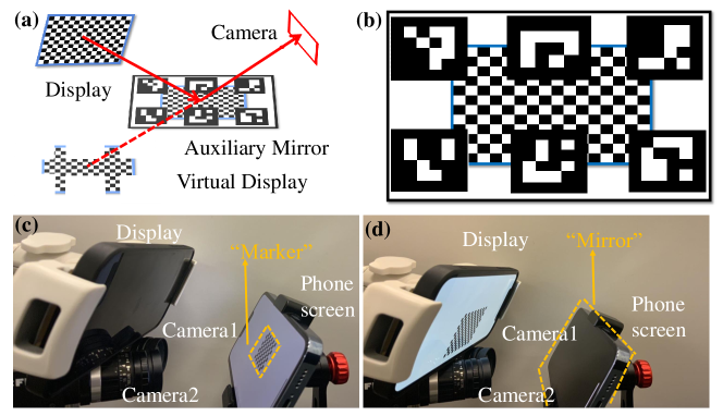
The key idea of our novel calibration method(see Fig 4.(c)(d)) is to replace the static marker-mirror by a switchable specular screen. In the “on-state”, the screen displays a known calibration pattern (e.g., a checkerboard pattern) that densely fills the entire FoV of both cameras. We evaluate the accurate pose of the screen in space from the respective camera images. Eventually, the screen switches to “off-state”: No pattern is displayed and the screen acts as mirror to observe the deflectometry display. This method allows to calibrate the display position without any marker occlusion while simultaneouly exploiting the camera’s FoV in a most efficient way, which ultimately leads to measurements at much higher accuracy compared to conventional calibration methods[46].
3 Results
We demonstrate the feasibility of our approach in real experiments. We first quantify the quality of our surface and normal reconstruction method by measuring a spherical bearing ball, which roughly has the same radius as a human eye. Eventually, we evaluate the mean relative gazing errors for fixed rotation positions of an realistic real-world eye model. The evaluated errors are all , with precision values . Moreover, we perform a qualitative gaze direction estimation with our method on a real human eye in-vivo. The following subsections describe our experiments and results in detail. A further evaluation of our method within the framework of a realistic simulation can be found in the supplementary material.
3.1 Quantitative evaluation of the surface reconstruction quality
As described above, our method relies on a high-quality deflectometric surface reconstruction for a reliable gaze estimation. For this reason, we first separately evaluate the quality of our surface reconstruction before evaluating the gaze estimation. As measurement object we use a metallic bearing ball with a well-defined radius that is subject to very little manufacturing tolerances (McMaster-Carr 1598K39, ). Our prototype setup to perform all measurements is shown in Fig. 6.(a). We use two machine vision cameras (Model: flea3 fl3-u3-13s2c) equipped with 9 mm objectives that face the object, which is illuminated by an iPhone 12 pro display (resolution pix). The system is calibrated using the novel calibration method described above.
We use the single-shot stereo-deflectometry method with iterative surface integration (detailed in section 2.1) to measure and reconstruct the spherical surface of the bearing ball. We capture a total of surface points and with respective surface normals in only one single-shot. An exemplary image from camera 1 is shown in Fig. 5.(a). The respective surface reconstruction (including normals) is shown in Fig. 5.(b). To quantify the quality of our reconstruction we calculate two metrics: The radius of the reconstructed surface and the precision at which the back-traced normals meet at one point (the center of the sphere). The radius of our reconstructed surface is calculated to , which deviates only from the specified radius of the bearing ball. To evaluate the precision of the calculated surface normals, we back-trace all surface normals towards the center of the sphere and estimate the sphere center by calculating their best-fit intersection point. Eventually the precision is calculated via the standard deviation of the absolute distance of the backtraced normals to the calculated center. We obtain a standard deviation of only .
3.2 Quantitative evaluation of the gaze estimation
| Rotation position | -4∘ | -2∘ | 0∘ | 2∘ | 4∘ |
|---|---|---|---|---|---|
| Mean relative error | 0.14∘ | 0.25∘ | 0∘ | 0.13∘ | 0.12∘ |
| Precision | 0.08∘ | 0.06∘ | 0.04∘ | 0.07∘ | 0.02∘ |
Quantifying the performance of our gaze estimation with high reliability requires the design of a systematic experiment. Evaluations of gazing directions using real human subjects can be too unreliable for our purposes, mainly for two reasons: (1) one possibility of such an evaluation might require a third-party eye tracker to deliver the ground truth for our measurement. The estimation error of this third-party eye tracker might be higher than the error of our method, which would lead to wrong conclusions. (2) another possible procedure requires the subject to look at a certain signal on the screen (e.g., a moving point) to calculate the ground truth gazing direction[15, 48]. Those methods require very accurate calibration and rely on the assumption that the human subject is not moving during the entire duration of the experiment and also really looks at the signal for most of the time, which introduces another source of error.
For these reasons, we designed an experiment that largely eliminates different sources of “third-party" errors, and focuses only on the accuracy of our system. Instead of a human subject, we use a realistic real-world eye model (with distinct cornea and sclera) that is mounted on a high-precision rotation stage. An image of our eye model mounted in our setup is shown in Fig. 6.(a). We rotate the eye model to several positions of our stage to accurately change the gazing direction by known angles. We emphasize that the ground truth gazing direction for the eye model on the stage is still unknown and can also not be evaluated in a reliable way (see above). For this reason, we define a “default” gazing direction by rotating the eye model to on the rotation stage, and eventually measure the gaze directions as relative angles w.r.t. the default gaze direction. For our evaluation, we rotate the stage to different rotation positions , comprised of , , , , and . We capture a single-shot measurement at one position and rotate to the next position until we have acquired a total of 20 measurements at each position. On average, we capture surface points with respective surface normals in each single-shot measurement at each rotation position. We emphasize that we never capture two consecutive measurements without having rotated the eye model. For each measurement at rotation position we calculate the relative gazing vector w.r.t. to the “default” position. Eventually, we calculate the mean relative error at each rotation angle as follows:
| (6) |
Here is the mean evaluated gazing angle of 20 performed measurements at rotation angle , and is the mean evaluated gazing angle of 20 performed measurements at rotation angle ( the “default” gazing angle). The results of this evaluation are summarized in Tab. 1. The mean relative gazing error is for all measurements with most errors even being below .
In a second step, we evaluate the precision of our method by calculating the standard deviation of our evaluated gazing angles at each rotation position :
| (7) |
is the measurement at rotation position , and in this experiment. As also shown in Tab. 1 the evaluated gazing precision is for all measurements.
We note again that it is generally hard to compare the quantitative evaluation of different eye tracking methods, as different papers use different error metrics and evaluation procedures. According to [1], it can be said in general that the best reported errors of current eye tracking methods vary within the range[1], which attests our method a significant improvement over the current state of the art.
3.3 Qualitative measurement on a real human eye in-vivo
In-vivo measurements on real human eyes differ from systematic measurements of a model eye under lab conditions: The human eye surface might be (partially) occluded by the eyelids or lashes. Also, the human sclera surface is, in reality, not as specular as the cornea surface and diffusely scatters parts of the incoming light, which leads to a contrast reduction in the imaged pattern[49]. Moreover, the sclera surface shows “little bumps” wherever a blood vessel is located close to the surface, which represents a significant deviation from its overall spherical shape.
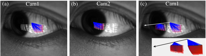
To demonstrate that our method can still work under these conditions, we perform a qualitative gaze evaluation on a real human eye in-vivo. The result is shown in Fig. 7. The pattern is clearly visible on both sclera and cornea and we can obtain a dense deflectometric surface and normal reconstruction. When tracing back the normals towards the sclera and cornea center, the “bumpy” sclera surface parts as well as the highly curved limbus region, produce normals that do not intersect cornea or sclera close to their center. As discussed, we treat those normals as “outliers” in our evaluation process, and reject them via a least square optimization process.
The reconstruction after outlier rejection is shown in Fig. 7.(a)and(b). The backtraced normals nicely intersect at two distinct center points (see Fig. 7.(c)). When plotting the reconstructed gazing vector in the coordinate system of camera 1 and overlaying both images (Fig. 7.(c)), it can be seen that the vector passes through the pupil center and points in the direction of the optical axis. This means that, within the boundaries of a qualitative evaluation, our method produces reasonable results on real human eyes in-vivo. As discussed above, a quantitative evaluation on real human eyes that is free from third-party error sources will require substantial experimental effort paired with extensive user studies on multiple human subjects, which is outside the scope of the contributions of this paper.
4 Summary, discussion, and outlook
This paper introduced a novel method for reflection-based eye racking that exploits dense 3D eye surface reconstructions from single-shot deflectometry measurements. State-of-the-art reflection-based methods (e.g., glint tracking) only sample the eye surface at points. In our real-world gaze evaluations shown in sec. 3.2, we acquire >40,000 points of the eye surface in each single-shot measurement, which leads to a calculated mean relative gaze error , at a precision . Moreover, we showed a first qualitative measurement on a real human eye in-vivo, which demonstrates the feasibility of our method for real-world applications.
Besides its single-shot ability and high accuracy, our method has additional interesting attributes that will potentially become important for future application scenarios: It does not rely on 2D eye texture features such as iris images or pupil center, whose exact position is prone to errors due to refraction of light rays at the cornea surface. Moreover, we only make minimal model assumptions about the eye shape. Although we motivate our method by the justified assumption that cornea and sclera are spherical in shape, this assumption is, strictly spoken, not required. It would already be sufficient for our method if the cornea and sclera are rotationally symmetric. In this case, all backtraced normals would meet along the optical axis of the eye, which can then be used to calculate the gaze.
Another interesting feature comes from the 3D imaging capability of deflectometry: The “byproduct” of our gaze estimation is a very accurate measurement of the eye surface. As described in[34], this surface measurement can be used to quantify vision impairments. In a potential VR/AR headset setting, this information can be used to correct vision impairments of the user ”on the fly", meaning that the user would not be required to wear contact lenses or glasses, and a previous calibration is not required.
In our future research, we will seek to further improve our method by replacing certain steps in our pipeline with data-driven approaches, and also by combining it with certain aspects of our inverse rendering-based technique[50, 51]. Moreover, we estimate that increasing the pattern coverage on the eye surface can also significantly contribute to the even higher accuracy of our method. We hope that our introduced method will become part of a new wave of accurate and fast eye-tracking methods that enable unprecedented features in VR/AR development and drastically improves prediction accuracy in clinical use and psychology research.
References
- [1] I. B. Adhanom, P. MacNeilage, and E. Folmer, “Eye tracking in virtual reality: a broad review of applications and challenges,” \JournalTitleVirtual Reality pp. 1–24 (2023).
- [2] R. Clark, J. Blundell, M. J. Dunn, J. T. Erichsen, M. E. Giardini, I. Gottlob, C. Harris, H. Lee, L. Mcilreavy, A. Olson et al., “The potential and value of objective eye tracking in the ophthalmology clinic,” \JournalTitleEye 33, 1200–1202 (2019).
- [3] N. Merali, D. Veeramootoo, and S. Singh, “Eye-tracking technology in surgical training,” \JournalTitleJournal of Investigative Surgery 32, 587–593 (2019).
- [4] R.-M. Rahal and S. Fiedler, “Understanding cognitive and affective mechanisms in social psychology through eye-tracking,” \JournalTitleJournal of Experimental Social Psychology 85, 103842 (2019).
- [5] R. S. Hessels and I. T. Hooge, “Eye tracking in developmental cognitive neuroscience–the good, the bad and the ugly,” \JournalTitleDevelopmental cognitive neuroscience 40, 100710 (2019).
- [6] Y. Zhao, D. Lindberg, B. Cleary, O. Mercier, R. Mcclelland, E. Penner, Y.-J. Lin, J. Majors, and D. Lanman, “Retinal-resolution varifocal vr,” in ACM SIGGRAPH 2023 Emerging Technologies, (2023), pp. 1–3.
- [7] K. Nishino and S. K. Nayar, “The world in an eye [eye image interpretation],” in Proceedings of the 2004 IEEE Computer Society Conference on Computer Vision and Pattern Recognition, 2004. CVPR 2004., vol. 1 (IEEE, 2004), pp. I–I.
- [8] F. Lu, T. Okabe, Y. Sugano, and Y. Sato, “A head pose-free approach for appearance-based gaze estimation.” in BMVC, (2011), pp. 1–11.
- [9] F. Lu, Y. Sugano, T. Okabe, and Y. Sato, “Inferring human gaze from appearance via adaptive linear regression,” in 2011 International Conference on Computer Vision, (IEEE, 2011), pp. 153–160.
- [10] J. Li and S. Li, “Gaze estimation from color image based on the eye model with known head pose,” \JournalTitleIEEE Transactions on Human-Machine Systems 46, 414–423 (2015).
- [11] N. Valliappan, N. Dai, E. Steinberg, J. He, K. Rogers, V. Ramachandran, P. Xu, M. Shojaeizadeh, L. Guo, K. Kohlhoff et al., “Accelerating eye movement research via accurate and affordable smartphone eye tracking,” \JournalTitleNature communications 11, 1–12 (2020).
- [12] F. L. Coutinho and C. H. Morimoto, “Free head motion eye gaze tracking using a single camera and multiple light sources,” in 2006 19th Brazilian Symposium on Computer Graphics and Image Processing, (IEEE, 2006), pp. 171–178.
- [13] C. A. Hennessey and P. D. Lawrence, “Improving the accuracy and reliability of remote system-calibration-free eye-gaze tracking,” \JournalTitleIEEE transactions on biomedical engineering 56, 1891–1900 (2009).
- [14] C. Mestre, J. Gautier, and J. Pujol, “Robust eye tracking based on multiple corneal reflections for clinical applications,” \JournalTitleJournal of biomedical optics 23, 035001 (2018).
- [15] J. Liu, J. Chi, and S. Fan, “A method for accurate 3d gaze estimation with a single camera and two collinear light sources,” \JournalTitleIEEE Transactions on Instrumentation and Measurement (2022).
- [16] D. Beymer and M. Flickner, “Eye gaze tracking using an active stereo head,” in 2003 IEEE Computer Society Conference on Computer Vision and Pattern Recognition, 2003. Proceedings., vol. 2 (IEEE, 2003), pp. II–451.
- [17] S.-W. Shih and J. Liu, “A novel approach to 3-d gaze tracking using stereo cameras,” \JournalTitleIEEE Transactions on Systems, Man, and Cybernetics, Part B (Cybernetics) 34, 234–245 (2004).
- [18] K.-H. Tan, D. J. Kriegman, and N. Ahuja, “Appearance-based eye gaze estimation,” in Sixth IEEE Workshop on Applications of Computer Vision, 2002.(WACV 2002). Proceedings., (IEEE, 2002), pp. 191–195.
- [19] S. Baluja and D. Pomerleau, “Non-intrusive gaze tracking using artificial neural networks,” \JournalTitleAdvances in Neural Information Processing Systems 6 (1993).
- [20] K. Krafka, A. Khosla, P. Kellnhofer, H. Kannan, S. Bhandarkar, W. Matusik, and A. Torralba, “Eye tracking for everyone,” in Proceedings of the IEEE conference on computer vision and pattern recognition, (2016), pp. 2176–2184.
- [21] W. Zhu and H. Deng, “Monocular free-head 3d gaze tracking with deep learning and geometry constraints,” in Proceedings of the IEEE International Conference on Computer Vision, (2017), pp. 3143–3152.
- [22] S. Patel and L. Tutchenko, “The refractive index of the human cornea: A review,” \JournalTitleContact Lens and Anterior Eye 42, 575–580 (2019).
- [23] Z. Zhu and Q. Ji, “Novel eye gaze tracking techniques under natural head movement,” \JournalTitleIEEE Transactions on biomedical engineering 54, 2246–2260 (2007).
- [24] M. C. Knauer, J. Kaminski, and G. Häusler, “Phase measuring deflectometry: a new approach to measure specular free-form surfaces,” in Optical Metrology in Production Engineering, vol. 5457 (SPIE, 2004), pp. 366–376.
- [25] M. C. Knauer, C. Richter, P. Vogt, and G. Häusler, “Measuring the refractive power with deflectometry in transmission,” \JournalTitleDGaO Proc (2008).
- [26] S. Höfer, J. Burke, and M. Heizmann, “Infrared deflectometry for the inspection of diffusely specular surfaces,” \JournalTitleAdvanced Optical Technologies 5, 377–387 (2016).
- [27] C. Faber, E. Olesch, R. Krobot, and G. Häusler, “Deflectometry challenges interferometry: the competition gets tougher!” in Interferometry XVI: techniques and analysis, vol. 8493 (SPIE, 2012), pp. 232–246.
- [28] E. Olesch, G. Häusler, A. Wörnlein, F. Stinzing, and C. van Eldik, “Deflectometric measurement of large mirrors,” \JournalTitleAdvanced Optical Technologies 3, 335–343 (2014).
- [29] G. Häusler, C. Faber, E. Olesch, and S. Ettl, “Deflectometry vs. interferometry,” in Optical measurement systems for industrial inspection VIII, vol. 8788 (SPIE, 2013), pp. 367–377.
- [30] P. Su, S. Wang, M. Khreishi, Y. Wang, T. Su, P. Zhou, R. E. Parks, K. Law, M. Rascon, T. Zobrist et al., “Scots: a reverse hartmann test with high dynamic range for giant magellan telescope primary mirror segments,” in Modern Technologies in Space-and Ground-based Telescopes and Instrumentation II, vol. 8450 (SPIE, 2012), pp. 332–340.
- [31] I. Trumper, H. Choi, and D. W. Kim, “Instantaneous phase shifting deflectometry,” \JournalTitleOptics express 24, 27993–28007 (2016).
- [32] F. Willomitzer, C.-K. Yeh, V. Gupta, W. Spies, F. Schiffers, A. Katsaggelos, M. Walton, and O. Cossairt, “Hand-guided qualitative deflectometry with a mobile device,” \JournalTitleOptics express 28, 9027–9038 (2020).
- [33] Y. Li, C.-K. Yeh, B. Xu, F. Schiffers, M. Walton, J. Tumblin, A. Katsaggelos, F. Willomitzer, and O. Cossairt, “A low-cost solution for 3d reconstruction of large-scale specular objects,” in Computational Optical Sensing and Imaging, (Optica Publishing Group, 2021), pp. CW4H–3.
- [34] H. Liang, E. Olesch, Z. Yang, and G. Häusler, “Single-shot phase-measuring deflectometry for cornea measurement,” \JournalTitleAdvanced Optical Technologies 5, 433–438 (2016).
- [35] Y. Zheng, Q. Chao, Y. An, S. Hirsh, and A. Fix, “Fringe projection-based single-shot 3d eye tracking using deep learning and computer graphics,” in Optical Architectures for Displays and Sensing in Augmented, Virtual, and Mixed Reality (AR, VR, MR) IV, vol. 12449 (SPIE, 2023), pp. 265–275.
- [36] L. Huang, M. Idir, C. Zuo, and A. Asundi, “Review of phase measuring deflectometry,” \JournalTitleOptics and Lasers in Engineering 107, 247–257 (2018).
- [37] H. Liang, T. Sauer, and C. Faber, “Using wavelet transform to evaluate single-shot phase measuring deflectometry data,” in Applications of Digital Image Processing XLIII, vol. 11510 (SPIE, 2020), pp. 404–410.
- [38] M. Takeda and K. Mutoh, “Fourier transform profilometry for the automatic measurement of 3-d object shapes,” \JournalTitleApplied optics 22, 3977–3982 (1983).
- [39] X. Su and W. Chen, “Fourier transform profilometry:: a review,” \JournalTitleOptics and lasers in Engineering 35, 263–284 (2001).
- [40] M. Ballester, H. Wang, J. Li, O. Cossairt, and F. Willomitzer, “Single-shot tof sensing with sub-mm precision using conventional cmos sensors,” \JournalTitlearXiv preprint arXiv:2212.00928 (2022).
- [41] E. Slogsnat and K.-H. Brenner, “Non-stereoscopic method for deflectometric measurement of reflecting surfaces,” \JournalTitleDGaO-Proceedings (Online-Zeitschrift der Deutschen Gesellschaft für angewandte Optik e. V.), ISSN pp. 1614–8436 (2009).
- [42] L. Huang, J. Xue, B. Gao, C. Zuo, and M. Idir, “Zonal wavefront reconstruction in quadrilateral geometry for phase measuring deflectometry,” \JournalTitleApplied optics 56, 5139–5144 (2017).
- [43] J. Wang, B. Xu, T. Wang, W. J. Lee, M. Walton, N. Matsuda, O. Cossairt, and F. Willomitzer, “Vr eye-tracking using deflectometry,” in Computational Optical Sensing and Imaging, (Optica Publishing Group, 2021), pp. CF2E–3.
- [44] J. Wang, T. Wang, B. Xu, O. Cossairt, and F. Willomitzer, “Accurate and fast vr eye-tracking using deflectometric information,” in Computational Optical Sensing and Imaging, (Optica Publishing Group, 2023), p. CTh2B.5.
- [45] H. Ren, F. Gao, and X. Jiang, “Iterative optimization calibration method for stereo deflectometry,” \JournalTitleOptics express 23, 22060–22068 (2015).
- [46] J. Wang, B. Xu, O. Cossairt, and F. Willomitzer, “Easy and flexible calibration approach for deflectometry-based vr eye-tracking systems,” in Computational Optical Sensing and Imaging, (Optica Publishing Group, 2022), pp. CTh5C–1.
- [47] Z. Zhang, “A flexible new technique for camera calibration,” \JournalTitleIEEE Transactions on pattern analysis and machine intelligence 22, 1330–1334 (2000).
- [48] A. N. Angelopoulos, J. N. Martel, A. P. Kohli, J. Conradt, and G. Wetzstein, “Event-based near-eye gaze tracking beyond 10,000 hz,” \JournalTitleIEEE Transactions on Visualization and Computer Graphics 27, 2577–2586 (2021).
- [49] T. Wang, F. Schiffers, F. Willomitzer, and O. Cossairt, “A mitsuba-based study on trade-offs between projection and reflection based systems in structured-light 3d imaging,” in OSA Imaging and Applied Optics Congress 2021 (3D, COSI, DH, ISA, pcAOP), (Optica Publishing Group, 2021), p. CW4H.2.
- [50] T. Wang, J. Wang, O. Cossairt, and F. Willomitzer, “Optimization-based eye tracking using deflectometric information,” \JournalTitlearXiv preprint arXiv:2303.04997 (2023).
- [51] O. Cossairt, F. Willomitzer, C.-K. Yeh, and M. Walton, “Low-budget 3d scanning and material estimation using pytorch3d,” in 2020 54th Asilomar Conference on Signals, Systems, and Computers, (IEEE, 2020), pp. 1316–1317.