Large-scale environment mapping and immersive human-robot interaction for agricultural mobile robot teleoperation
Abstract
Remote operation is a crucial solution to problems encountered in agricultural machinery operations. However, traditional video streaming control methods fall short in overcoming the challenges of single perspective views and the inability to obtain 3D information. In light of these issues, our research proposes a large-scale digital map reconstruction and immersive human-machine remote control framework for agricultural scenarios. In our methodology, a DJI unmanned aerial vehicle(UAV) was utilized for data collection, and a novel video segmentation approach based on feature points was introduced. To tackle texture richness variability, an enhanced Structure from Motion (SfM) using superpixel segmentation was implemented. This method integrates the open Multiple View Geometry (openMVG) framework along with Local Features from Transformers (LoFTR). The enhanced SfM results in a point cloud map, which is further processed through Multi-View Stereo (MVS) to generate a complete map model. For control, a closed-loop system utilizing TCP for VR control and positioning of agricultural machinery was introduced. Our system offers a fully visual-based immersive control method, where upon connection to the local area network, operators can utilize VR for immersive remote control. The proposed method enhances both the robustness and convenience of the reconstruction process, thereby significantly facilitating operators in acquiring more comprehensive on-site information and engaging in immersive remote control operations. The code is available at: https://github.com/LiuTao1126/Enhance-SFM
Index Terms:
Three-dimensional mapping, Remote control, VR, OpenMVG, LoFTR, Superpixel segmentation, Agricultural mobile robotsI Introduction
The advent of agricultural machinery has brought about a revolutionary change in agricultural production, with its widespread use significantly reducing the need for manual labor [1]. However, traditional agricultural machinery still requires on-site human operation, which not only increases the transportation costs for agricultural workers but also poses potential health risks to the operators. Emerging autonomous operation technologies have mitigated these issues to some extent, yet the unstructured and complex nature of agricultural environments—such as sudden changes caused by natural disasters, partial machine malfunctions, or instability in GPS navigation[1, 2]—could potentially affect the efficiency of autonomous operations in agricultural robots. Against this backdrop, remote operation technology provides an effective solution for both traditional agricultural machinery and as a supplement to autonomous operations. It effectively combines human intelligent decision-making with machine motion, providing real-time human intervention capability for agricultural robots. Integrating remote operation technology can minimize machinery downtime and enhance its operational capability in various environments.
Traditional teleoperation methods often involve placing cameras at the operation site to capture real-time visuals. These information are then displayed on a computer screen, guiding the operation of the robots [3, 4, 5]. However, these conventional methods based on video streams have significant limitations, including a single, limited viewpoint and an inabiity to provide operators with 3D information, which may impede efficient operation[6] .In order to overcome these constraints, Nielsen et al.[7] and Murakami et al.[8] have attempted to provide operators with 3D map information in addition to video feeds. Valiton [9] explored the use of two cameras to offer different crucial viewing angles, aiding operation. Experimental validation found that the use of multiple cameras to change perspectives can be beneficial for the operator’s work. However, this approach is not well-suited for outdoor agricultural scenarios.
As for advancements in display technology, more and more researchers have started turning to VR technology[10, 11, 12] . Bian et al. [13] introduced a three-dimensional visual feedback subsystem, built on VR technology, designed to provide a 3D perception to the operator. This system delivered immersive visual feedback to the operator, enhancing their spatial awareness during operation; Lipton et al. [14] and Su et al. [15] incorporated the operator into a VR control room, where the visual scenes captured from various camera perspectives were projected onto the VR headset. Sun et al. [15] advanced an innovative approach that integrates Mixed Reality (MR) with remote machine operation .This method involved the development of a sophisticated MR interface, which effectively amalgamates elements of the real and virtual environments. Multiple studies have demonstrated the potential of VR in teleoperation. VR can provide more immersive information about the operation site, compared to traditional displays[16, 17] . Building on these advancements, this study leverages VR technology to create comprehensive virtual representations of large-scale agricultural environments. The aim is to establish an immersive human-robot interaction methodology for teleoperating agricultural mobile robots within these simulated environments.
In the field of digital map reconstruction, Significant advancements have been made , thanks to improvements in computational capacity, algorithms, and image acquisition techniques. Lv et al. [18] , Zhang et al. [19] , and Sun et al. [20] have utilized Kinect cameras to capture RGB-D data, initiating active 3D reconstruction attempts in various fields. However, the depth acquisition range of depth cameras is relatively limited[21] , making it unsuitable for direct reconstruction of large outdoor agricultural scenarios. The data collection method employed in this study involves using drones for aerial photography. UAV, due to their superior viewpoint, have become an ideal means of obtaining visual information. Gonçalves et al.[22] , Berra & Peppa[23] , and Meinen & Robinson et al. [24] have used UAV to capture large-scale outdoor scene data, followed by 3D map reconstruction using the SfM-MVS method.
It is worth noting that 3D reconstruction remains a significant research field, having developed numerous effective algorithms, including the OpenMVS algorithm, the latest NERF algorithm, COLMAP, among others. Nevertheless, the quality of 3D reconstruction is influenced by several factors, such as the texture richness of the object and the shooting angle, among others [22] . Especially in low texture scenes, the reconstruction has been a challenging issue, which is significantly influenced by the extraction, description, and matching methods of feature points. In this regard, the SIFT method, commonly used in SfM, does not perform well, and an insufficient number of feature points will directly affect the reconstruction outcome [25] .In order to address this issue, Yang & Jiang [26] utilized films of spark patterns overlaid on the object’s surface to increase the feature points. Hoshi S et al [25] combined SuperPoint , SuperGlue, and LoFTR from deep learning, using SuperPoint +SuperGlue to process regular image areas and LoFTR to handle low texture areas. These research achievements have brought new possibilities for digital map reconstruction.
In the domain of Human-Robot Interaction (HRI), merging the virtual environment with the control of machines in the real world is an important area of research .The Robot Operating System (ROS) is commonly used on the machine side. Virtual environments have seen extensive application in gaming, giving rise to powerful game engines like Unity and Unreal Engine . Hussein et al. [27] proposed a framework that links Unity with ROS, using WebSocket for message decoding and encoding across different platforms. To develop an automatic delivery robot, Liu et al. [28] (2020)mapped the ROS robot’s virtual model in Unity to a real robot. This approach allows for a successful perception match between the real world where the robot is located and the virtual world. Mizuchi [28] incorporated Virtual Reality (VR) and proposed a new software architecture. This study provides a virtual identity for users in the virtual world, allowing interaction with the virtual environment through VR devices (headsets, controllers). Furthermore, a bridging mechanism between Unity and ROS was developed to support more rapid interactions. Meanwhile, Roldán et al. [30] took a unique approach to developing a Virtual Reality interface. He utilized multiple ROS packages along with Unity assets. The resulting interface, built on the combination of ROS and Unity, is capable of controlling multiple robots. Connecting the virtual world with machine control offers many benefits. When the virtual world effectively represents the real world, the operator can observe the world from any changed perspective without impacting the real world. This method of observation allows the operator to glean more information than from observing the real world directly.
Rooted in the goal of achieving immersive remote control, this research proposes a framework for the digital reconstruction of large-scale agricultural scenarios and immersive teleoperation .We utilize UAV for data collection. To accommodate the reconstruction of large-scale outdoor agricultural maps, We developed a video segmentation algorithm to minimize the data volume. Following this, to adapt to agricultural reconstruction, improved SfM algorithms and MVS are utilized for the process. The resulting digital agricultural map is then placed into VR for immersive viewing. Our system uses the TCP/IP to facilitate real-time control and location tracking of agricultural machinery in the VR setting. In my research, The position of the agricultural machinery is updated in real time through the VR head-mounted display, offers operators a powerful capability to gather on-site information. Our research not only provides a novel approach for the remote operation of agricultural robots but also makes a contribution to the field of three-dimensional reconstruction.
II Materials and methods
II-A Study Site
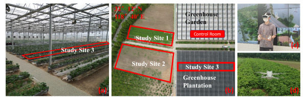
We conducted experiments in a total of four agricultural settings. The study sites were located in Ge Guan Ecological Park, Nanjing (32°12’N, 118°40’E). Study site 1 was an outdoor farmland cultivated with vegetables, while Study site 2 was an uncultivated area, as illustrated in Figure 1b. Study site 3 was part of the Greenhouse Plantation, where strawberries were grown as depicted in Figure 1a. The control room was situated within the Greenhouse Garden, where the operator remotely controlled the agricultural robots through a network. Figure 1c illustrates the operator’s control screen during remote operation.
DJI®Mini 3 Pro drone (SZ DJI Technology Co., Shenzhen, China) is used to shoot footage at 1080p and 30fps. The drone flies at a height of 5m(Study site1,2) and 1.5m(Study site3) and adjusts the angle of view between 90° and 60°. The entire shooting process is controlled by a remote controller. Due to hand instability, the flight speed is not stable but is maintained at a speed of approximately 1m/s to 2m/s. The drone follows a flight pattern resembling a series of connected ”L” shapes. It moves first from a close point to a distant point, then performs a lateral movement to the left or right. This sequence is then repeated.
II-B Feature-based video segmentation
For subsequent processing, it is necessary to split the captured video into images. If the video are directly divided at regular intervals, the unstable speed of the drone will cause the overlap rate between images to be inconsistent. Areas with slow flight will have too much overlap, increasing computational cost. In areas with fast flight, the degree of overlap will decrease, which may even lead to the inability to calculate the pose. In addressing the issue of variable drone speed, adopting fixed-distance shooting [22], segmentation based on overlap can also be viable solutions. However, when capturing irregular objects, the utilization of fixed-distance shooting and overlap-guided segmentation may yield suboptimal results. Certain complex textures, particularly in areas featuring intricate internal structures, such as congregations of concave surfaces, may be overlooked and not captured during the shooting process. However, utilizing feature points as a standard for overlap allows for segmentation based on the richness of these feature points. This approach is more robust compared to using the degree of image overlap as a standard. Following such processing, the shooting method can become more flexible, and the subsequent processing is simplified, making it more suitable for novices.
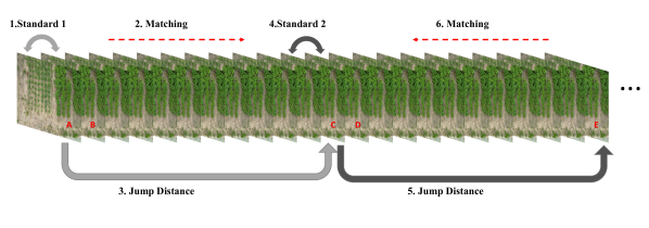
This method utilizes the SIFT algorithm to extract and match feature points between images. For each segmentation, we set an evaluation criterion based on the number of matched feature points between the saved frame and its adjacent frame. The subsequent images’ feature points are continuously extracted until the number of matching points between the new image and the first image falls within the range of 50% to 33.3% according to the evaluation criteria. This approach ensures that all segmented images meet the computational requirements for subsequent calculations, while simultaneously reducing computational costs. To further optimize the algorithm, we employ a strategy of determining the jump distance and conducting iterative searches to enhance segmentation efficiency. The specific process is shown in Figure 2. Image A, Image C, Image E will be retained, and other images will be deleted. The logarithms of matched feature points between images A and B and between images C and D will serve as criteria in their respective intervals. The working flow of the video segmentation algorithm is roughly shown as Algorithm 1.
II-C Three-dimensional Point Cloud Reconstruction based on an Enhanced SfM
Prior to performing reconstruction, camera calibration is a prerequisite step. This process is vital. It involves determining the camera’s intrinsic parameters, which subsequently enable a more accurate reconstruction. For this purpose, we created a calibration board with a 7x10 checkerboard pattern. This pattern allows for the accurate determination of spatial relationships between different parts of the field of view. We captured 25 images with varying degrees of rotation and translation to provide a robust and comprehensive calibration. These images were then used to compute the camera’s intrinsic parameters. The form of calculated camera intrinsic parameters is:
| (1) |
The parameters and represent the focal length of the camera, measured in pixels. They correspond to the focal length in the horizontal and vertical directions of the image, respectively. The parameters and denote the coordinates of the principal point, also measured in pixels.
In reconstruction, OpenMVG is employed as the primary pipeline. OpenMVG is a multi-view based method for camera pose estimation and sparse reconstruction[31]. It can directly handle multi-view images without requiring any additional image information. This reduces the reliance on GPS and makes it more suitable for complex agricultural environments. OpenMVG utilizes SIFT as its main feature matching technique, exhibiting strong robustness and outperforming the majority of current state-of-the-art algorithms. However, the performance of the SIFT algorithm is suboptimal in weakly textured areas. Due to the complexity of agricultural domains, which results in uneven texture distribution in scenes, the applicability of OpenMVG in agriculture is diminished.
In this study, OpenMVG 2.0 incremental reconstruction is utilized. Incremental reconstruction employs SIFT for feature extraction and matching. Features are extracted from all images, and for each feature point, a 128-dimensional descriptor (4×4×8) is formed. Feature matching is carried out so that each image is matched with every other image. In a set of n images, each image is matched n-1 times. This process consumes a considerable amount of time and computational resources. SIFT can more accurately link different frames together, but its matching quality may decrease for images with poor coverage and weak textures.
To enhance feature matching in areas with low texture, this study utilizes pre-trained LoFTR weights for deployment. LoFTR is a Transformer-based feature extraction algorithm [32] . It operates through a two-stage process: coarse-grained matching followed by fine-grained matching. The coarse-grained stage obtains the initial match locations, while the fine-grained stage refines these matches with more precision. The matching results are more accurate and robust after undergoing both coarse-grained and fine-grained steps. LoFTR’s end-to-end learnable design allows it to obtain more matching points in weakly textured areas.
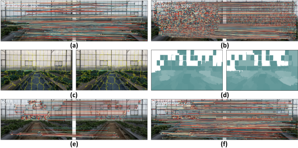
In this paper, we employ LoFTR trained by Megadepth [33] . We have integrated LoFTR into OpenMVG and applied it in conjunction with SIFT to achieve more effective feature matching in low-texture regions. Following SIFT processing, LoFTR will reprocess the feature points in the dataset. However, not all image pairs are subjected to LoFTR processing; we have set a fixed window matching with a window size of 5, and only image pairs within this window range are subjected to LoFTR. After obtaining the results from SIFT and LoFTR, the images are segmented into superpixels using the imple Linear Iterative Clustering (SLIC)[33] algorithm. The central formula of the SLIC algorithm calculates the distance between each pixel and the closest superpixel center. This distance computation enables the assignment of each pixel to its nearest superpixel center. The formula is represented as follows:
| (2) |
Here, represents the distance between a pixel and the center of the corresponding superpixel. , , and denote the Lab color values of the pixel, while , , and represent the Lab color values of the superpixel center. Additionally, and correspond to the spatial positions of the pixel, and denotes the compactness coefficient, which is utilized to balance the influences of color and spatial distances. In this study, the predefined number of superpixels (segments) is set to 100, accompanied by a compactness coefficient of 10 and a Gaussian filter with a sigma value of 1. Following superpixel segmentation, the feature point count within each superpixel and the average feature count per superpixel in the image are computed. As depicted in Figure 3d, distinct colors are employed to represent varying quantities of feature points, ranging from white to cyan, indicating increasing feature point abundance to scarcity. The standard is set as follows:
| (3) |
Here, refers to the Feature Count of the th superpixel. Feature points above this standard are considered to be in a feature-rich area, while those below the standard are classified as being in a weak texture area. Only the LoFTR feature values in the weak texture areas are preserved. This ensures that feature points in strong texture areas are from SIFT, while those in weak texture areas are from both SIFT and LoFTR. However, Lofrt solely provides the XY coordinates of feature points and does not generate scale and orientation values. In this context, a nearest-neighbor search based on the squared Euclidean distance is utilized, as Equation 4.
| (4) |
The algorithm identifies the SIFT feature points closest to the feature points obtained through Loftr and replicates their scale and orientation values.
The merged feature points are then filtered based on geometric consistency constraints, and incorrect matches from LoFTR and SIFT are removed. Finally, the algorithm starts from a single photograph and continually adds new images that have the most matching feature points with the current reconstruction. This involves solving the Perspective-n-Point (PnP) problem to estimate the new camera pose, and incrementally adding 3D points. During triangulation and camera positioning, Bundle Adjustment (BA) is used for optimization. While a significant amount of time is spent in BA, it effectively reduces errors and improves the accuracy of the reconstruction.
II-D Digital Agricultural Map Construction Using MVS Reconstruction
After obtaining a sparse point cloud, OpenMVS is utilized to process it. Firstly, preprocessing is performed on each of the images, addressing issues such as distortion and color correction. Next, depth estimation is conducted for every photo, assigning a depth value to each pixel. The depth estimation results from all images are fused to create a complete, dense point cloud map, and outlier values are processed. Subsequently, the dense point cloud map is converted into a 3D mesh.
During the 3D meshing process, a series of optimizations and improvements are carried out, including mesh simplification, denoising, smoothing, and hole filling. The processed 3D mesh is then assigned UV coordinates for texture mapping. Following this, a 2D texture atlas is generated. To ensure the quality of the model, color blending is performed on texture atlases created from different images. Finally, the texture is assigned to the 3D mesh to generate an accurate textured 3D model.
II-E Immersive Digital Map Viewing in VR
After obtaining the three-dimensional digital agricultural map, the map is used for immersive visualization display. Unity 3D is a powerful game development engine with strong capabilities in rendering and displaying 3D models, as well as processing and creating complex graphics. In addition, it supports cross-platform development on various operating systems, including Windows, Android, and Ubuntu. We utilize Unity for digital maps and VR application development. The digital agricultural map is imported into Unity at a scale approximating reality, and through Unity’s rendering and processing, it is presented with improved visualization.
In the display devices, ByteDance’s PICO 4 VR device is utilized. The PICO 4 is a powerful VR device capable of showcasing a 4K+ resolution, 20.6 PPD, and a 105° wide field of view. Notably, the PICO 4 supports a high refresh rate of 90Hz. As a recent outstanding VR device, it has undergone significant optimizations in terms of weight and wearing comfort, making it more suitable for remote operation and extended usage. Furthermore, the PICO 4 is equipped with a Qualcomm Snapdragon XR2 processor and an Android system, allowing for direct application development without the need for computer-side streaming. Due to its excellent performance and comfort, the PICO 4 serves as an ideal VR device, assisting operators in prolonged remote operations.
In the development process, the project requires the use of the XR Interaction Toolkit package available in Unity. The XR Interaction Toolkit is a cross-platform tool for VR/AR interaction development, featuring a range of functionalities that support VR devices. It helps us obtain input and output information from VR devices, particularly regarding controller input and head pose input. To accommodate the PICO 4, it is necessary to import the PICO Unity Integration SDK provided by PICO’s official source into the Unity project, ensuring compatibility with the PICO 4. Within the project, input from the left-hand controller is employed to control the movement of the virtual character’s position. Operators can utilize the controller to move forward, backward, and sideways. Additionally, virtual reality captures changes in head orientation, which are utilized to control the rotation of the viewpoint.
II-F TCP-based Closed-Loop Control for Remote Teleoperation
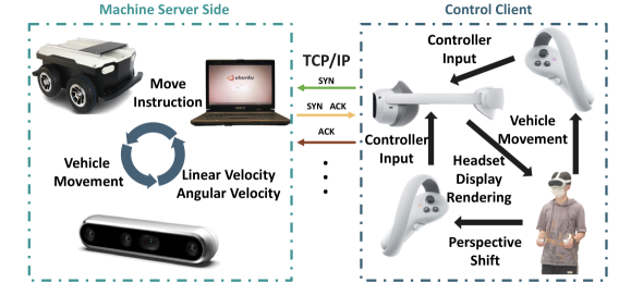
The control end and the machine end are connected using the TCP protocol to establish communication. The machine-end computer serves as the server, while the PICO 4 functions as the client. The left-hand controller of the PICO 4 is used to control the movement of the character’s viewpoint within the digital scene, while the input from the right-hand controller is directly collected and sent to the server end. TCP communication is facilitated through Unity’s .NET Framework. The StreamReader and StreamWriter classes are utilized to send and receive string messages. Upon receipt of control instructions from the PICO 4 at the robot end, the instructions are immediately forwarded to the server. The server’s ROS system receives these instructions through Python, which in turn controls the movement of the robot.
Upon receiving the instructions, the ROS robot publishes a Twist message type to the cmd_vel topic. The Twist message type includes linear and angular vectors, representing linear velocity and angular velocity, respectively. cmd_vel is a standard ROS topic that communicates with the underlying drive node of the ROS robot. The entire process is seamlessly controlled through a publish/subscribe model that interfaces with hardware drivers, enabling ROS control.
In open-loop control scenarios, it becomes increasingly difficult to accurately predict the position of the mobile robot due to the accumulation of errors during motion. To address this issue, we employ the RealSense D455 camera as a visual odometry system to determine the robot’s displacement and rotation angle. The RealSense D455 is a depth camera designed by Intel, capable of capturing both RGB and depth information. This camera is suitable for a shooting range of 0.6 to 6 meters, and its depth estimation error is controlled within 2% for objects within 4 meters.
In the project, the camera is mounted on the front of the mobile robot to calculate its movement by capturing depth changes on the ground in front of robot. Forward and backward motion primarily relies on the vertical changes in the depth image, while the rotation angle is determined by calculating the average distance on each side and the baseline distance. To reduce the impact of noise, the acquired depth information is processed through spatial and temporal filters. The filtered data is then used to compute average distances and rotation angles, enabling real-time estimation of the robot’s position and pose. The robot’s position and pose data are transmitted in real-time via TCP to the virtual reality (VR) environment. The robot’s position in VR is updated accordingly, providing the operator with a real-time understanding of the robot’s status.
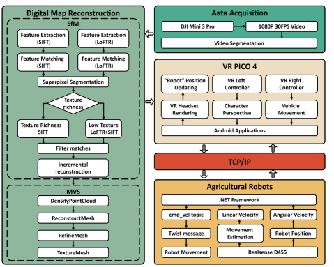
II-G Overall Framework
To achieve immersive teleoperation, we propose a system with an overall workflow as shown in the diagram. The entire system mainly consists of data acquisition, digital map reconstruction, VR visualization, and immersive closed-loop control. The drone captures video footage to obtain specific scene data, which is then matched and segmented frame-by-frame using feature points. The segmented data undergoes reconstruction using a multi-view geometry (OpenMVG) algorithm that integrates LOFTR, followed by the construction of a complete digital agricultural map using OpenMVS. The agricultural map, rendered with Unity, is then displayed immersively in VR. Teleoperation information exchange is facilitated by a direct connection between VR and the ROS robot. Through message communication, control messages are sent from VR to the robot, and the robot’s position is updated in real-time within VR, forming a closed-loop control framework.
III Results and Discussion
III-A Impact of Video Segmentation Algorithms
To reduce a large amount of redundant data, we have developed an algorithm that segregates data based on feature points. In order to ascertain the effectiveness of the algorithm proposed, four sets of experiments were conducted, with each set operating at different flight speeds. The first set operated at speeds ranging from 0 to 2 m/s. The second set functioned at speeds between 0 and 1 m/s, while the third set varied from 0 to 4 m/s. For the fourth set, we operated within a 0 to 4 m/s range, but each flight trajectory involved two accelerations and two decelerations, one within a 0 to 1 m/s range and another within a 0 to 4 m/s range.
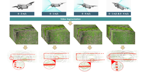
Due to the utilization of manual control during the experiment, our measurements might not have been absolutely precise, but they were sufficiently accurate to affirm the validity of the proposed algorithm. Results obtained from the experiments conducted at four different speeds were used to compute the camera pose. As can be seen in Figure 6, the number of images from the experiment was significantly reduced. Whether at straight line segments or corners, the overall distribution of images was relatively uniform. Especially at the corners, the drone’s speed was reduced to zero before making lateral movements. This process, owing to alterations in drone speed and pauses, can result in a considerable volume of redundant imagery, thus escalating data volume. Nevertheless, our algorithm exhibited extraordinary effectiveness in this context.
Moreover, there was no loss of images throughout the derivation of camera pose; all images underwent camera pose derivation. The distribution of images is anchored on these feature points; in regions with rich textures, the images are more densely accumulated, and the quantity increases, thereby facilitating the acquisition of more comprehensive data. Conversely, in low texture regions, images are more scattered, and their quantity is reduced, thus lowering computational costs.
| Data Acquisition Area | Video duration | Number of original images | Number of processed images |
|---|---|---|---|
| Test Area 1 | 188.6s | 5655 | 417 |
| Test Area 2 | 191.0s | 5726 | 452 |
| Test Area 3 | 62.0s | 1860 | 141 |
Table 1 presents the results obtained after segmenting the video footage captured from the three study sites employed in our subsequent experiments. Shooting at a rate of 30 frames per second resulted in abundant data acquisition with a high volume of images. However, the shooting process also generated a significant amount of redundant data. Following processing, a notable reduction in the volume of the resulting images was observed.
III-B The Performance of Reconstruction
A comparative study was conducted between the conventional SfM algorithm and our enhanced SfM method (SIFT+LoFTR) across various experimental sites. The experiments took place in three distinct testing areas: Test Area 1, Test Area 2, and Test Area 3. In each location, drones were utilized for filming purposes, following which our proposed video segmentation technique was applied to generate a respective count of 417, 452, and 141 images. Upon obtaining this data, a comparative analysis was performed.
In our point cloud reconstruction results, we utilized the SfM Scene Root Mean Square Error(RMSE) for estimating the performance. RMSE computes the error between the reconstructed 3D points and the actual 3D points. It is the square root of the average of squared re-projection errors across all images and is frequently employed for assessing errors in the field of three-dimensional reconstruction. RMSE is commonly employed as a measure to assess the accuracy of 3D structure reconstruction or camera pose estimation.
| Study site | Views | Method | RMSE | Number of Points produced by SfM | Points validated |
| Study site 1 | 417 | OpenMVG | 0.411572 | 630,342 | 0.736434 |
| 417 | OpenMVG+LoFTR | 0.373865 | 1,222,507 | 0.968 | |
| Study site 2 | 452 | OpenMVG | 0.335612 | 210,103 | 0.939655 |
| 452 | OpenMVG+LoFTR | 0.270256 | 1,606,487 | 1 | |
| Study site 3 | 141 | OpenMVG | 0.434822 | 37,358 | 0.928 |
| 141 | OpenMVG+LoFTR | 0.368285 | 211,771 | 0.967742 |
| (5) |
Here, , , and are the predicted , , and coordinates of a point, respectively, whereas , , represent the actual observed point locations.
To quantify the improvement, we conducted a statistical analysis on the ”Number of Points” for both traditional and enhanced algorithms, thus comprehending the contribution of LOFTR to algorithmic enhancement. The point cloud is capable of representing scene information and can reflect the algorithm’s performance in presenting the intricacies and complexity of the scene. Additionally, the determination of camera pose requires the participation of high-quality point clouds. To substantiate the validity of projected points during the 3D reconstruction process, we employ ’Points Validated’ as an evaluative measure. Verification is conducted for all projected points during the 3D reconstruction process. ’Points Validated’ represents the percentage of correctly matched point pairs within the total number of projected points.
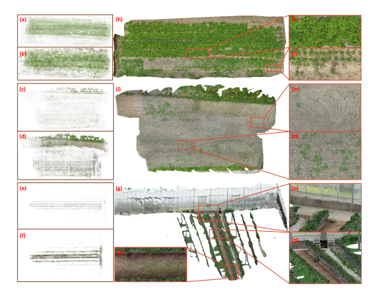
As illustrated in the table 2, the enhancements made to the SfM algorithm have resulted in an improvement in the RMSE. This implies that the modified algorithm possesses improved robustness. Furthermore, the data from the table signifies a considerable increase in the number of feature points identified by the modified algorithm. This observation is evident from Figure 7a-f, where the application of the enhanced SfM method demonstrates a notably improved overall presentation. A higher count of feature points can contribute to a more precise estimation of camera pose, which is a critical element for successful SfM implementations. Also, the increase in feature points enables the algorithm to capture more intricate and rich information from the scene, thereby enhancing the algorithm’s capability to manage complex environments and provide a more comprehensive representation of the 3D structure. The increment in ’Points Validated’ suggests that a higher percentage of identified points have been authenticated in the modified algorithm, further attesting to its effectiveness. The validation process discards inaccurately matched point pairs, ensuring that the remaining points make a positive contribution to the 3D reconstruction and camera pose estimation. Consequently, the elevated validation rate in the improved algorithm corroborates the claim that the refined algorithm offers more accurate feature point detection.
After the application of the Proposed Enhanced SfM and MVS, the digital maps for three study sites are presented in Figure 7h-g. Study site 1 and 2 depict a flat field, as evidenced by the enlarged maps, where even minute vegetation details have been accurately reconstructed. Figures 7k-l offer intricate views of ground-level vegetation, allowing for the discernment of individual leaves. Figures 7m-n showcase the texture of bare cultivated land and the presence of scattered weeds. Transitioning to Scene 3, which features a greenhouse environment, data acquisition was limited to three sides. Notably, Figures 7o-q vividly demonstrate the successful reconstruction of both corridor spaces and transparent glass surfaces.
III-C Immersive viewing and control
We integrated this digital agriculture map into a Virtual Reality (VR) Android application under the support of the Unity engine. Experiments were conducted in outdoor agricultural environments to validate the immersive display effects of the digital farm within the Virtual Reality (VR) setup. Once imported into Android, the scene undergoes rendering through Unity. The digital agriculture map not only replicates the appearance of an authentic agricultural landscape but can also present varying illumination effects under the rendering process.
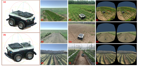
Within the VR device, operators find themselves immersed in a virtual farm environment. Figures 8c-e illustrate the results of map import into Unity. Regrettably, the maps undergo a simplification process upon being imported into Unity, leading to a decrease in map quality. However, the scene maintains a level of quality that meets the intended standards. The maps are presented to operators, enhancing their immersive understanding of the real-world scenario. Moreover, the VR headset will present distinct visuals to each eye, providing operators with additional 3D information due to the disparity in perspectives between the two images as Figures 8j-l. Traditional computer monitors only display the operational site’s conditions, and the exterior of the monitor often distracts the operator. Even if it’s possible to transmit information from multiple on-site cameras, thus gaining information from multiple viewpoints, the fixed nature of these viewpoints is not advantageous for outdoor environments.In contrast, our approach frees operators from physical restrictions in scene movement, enabling them to perform feats like ”walking through walls” or ”flying” in a virtual environment. By using the controller in their left hand, operators can identify the optimal viewpoint, enabling movements and perspectives that would be impossible to achieve in real-world scenarios.
To facilitate users in remote operations, the mobile robot has also undergone a 3D reconstruction, and its model has been imported into the VR Android application, as illustrated in Figure 8a-b depicting the 3D model of the robot. The VR right controller primarily manages the control of the robot. The gathered controller information is transmitted in real-time over the network to the robot end, directing the ROS (Robot Operating System) machine for operation. The robot’s movement information is acquired through the camera and then transmitted back to the VR environment via the network. This enables operators within the VR setup to observe real-time updates of the robot’s position, establishing a closed-loop system. We conducted tests at three distinct study site 1,2,3 and Figures 8f-l depict screenshots of vehicle movements in both the real-world environment and the VR environments. It is evident that VR enables the observation of optimal vehicle movement by allowing changes in perspective. This also validates the feasibility of the research framework.
IV 4. Conclusions
This study proposes a novel methodology for the reconstruction of agricultural digital maps and a Virtual Reality (VR) remote operation control system. In the realm of agricultural digital map reconstruction, we introduce a video segmentation technique that uses feature points as benchmarks. This method demonstrates significant adaptability, enabling transferability to any three-dimensional reconstruction algorithm, while concurrently achieving computational cost-effectiveness. Additionally, we have optimized SfM algorithm by integrating LoFTR and SIFT, thereby enabling the generation of more reliable and comprehensive reconstruction outcomes. From a control perspective, we present a closed-loop control mechanism that integrates VR Android software with ROS robots. This approach surpasses traditional display screen methods by proposing a superior remote control method that enhances the operator’s access to more comprehensive 3D scene information, ensuring immersive control. Moreover, the system framework does not excessively rely on robot hardware, facilitating its transferability to other machines for experimentation. This aspect provides a more effective solution for robot remote control, thereby facilitating farm management for agricultural administrators and the execution of activities that could potentially pose harm to human health.
References
- [1] Bechar, A., & Vigneault, C. (2016). Agricultural robots for field operations: Concepts and components. Biosystems Engineering, 149, 94-111.
- [2] Edan, Y., Han, S., & Kondo, N. (2009). Automation in agriculture. Springer handbook of automation, 1095-1128.
- [3] Hainsworth, D. W. (2001). Teleoperation user interfaces for mining robotics. Autonomous robots, 11(1), 19-28.
- [4] Adamides, G., Berenstein, R., Ben-Halevi, I., Hadzilacos, T., & Edan, Y. (2012, September). User interface design principles for robotics in agriculture: The case of telerobotic navigation and target selection for spraying. In Proceedings of the 8th Asian Conference for Information Technology in Agriculture, Taipei, Taiwan (Vol. 36).
- [5] Ersahin, G., & Sedef, H. (2015). Wireless mobile robot control with tablet computer. Procedia-Social and Behavioral Sciences, 195, 2874-2882.
- [6] Passenberg, C., Peer, A., & Buss, M. (2010). A survey of environment-, operator-, and task-adapted controllers for teleoperation systems. Mechatronics, 20(7), 787
- [7] Nielsen, C. W., Goodrich, M. A., & Ricks, R. W. (2007). Ecological interfaces for improving mobile robot teleoperation. IEEE Transactions on Robotics, 23(5), 927-941.
- [8] Murakami, N., Ito, A., Will, J. D., Steffen, M., Inoue, K., Kita, K., & Miyaura, S. (2008). Development of a teleoperation system for agricultural vehicles. Computers and Electronics in Agriculture, 63(1), 81-88.
- [9] Valiton, A., Baez, H., Harrison, N., Roy, J., & Li, Z. (2021, May). Active Telepresence Assistance for Supervisory Control: A User Study with a Multi-Camera Tele-Nursing Robot. In 2021 IEEE International Conference on Robotics and Automation (ICRA) (pp. 3722-3727). IEEE.
- [10] Stotko, P., Krumpen, S., Schwarz, M., Lenz, C., Behnke, S., Klein, R., & Weinmann, M. (2019, November). A VR system for immersive teleoperation and live exploration with a mobile robot. In 2019 IEEE/RSJ International Conference on Intelligent Robots and Systems (IROS) (pp. 3630-3637). IEEE.
- [11] Bazzano, F., Gentilini, F., Lamberti, F., Sanna, A., Paravati, G., Gatteschi, V., & Gaspardone, M. (2016). Immersive virtual reality-based simulation to support the design of natural human-robot interfaces for service robotic applications. In Augmented Reality, Virtual Reality, and Computer Graphics: Third International Conference, AVR 2016, Lecce, Italy, June 15-18, 2016. Proceedings, Part I 3 (pp. 33-51). Springer International Publishing.
- [12] Pérez, L., Diez, E., Usamentiaga, R., & García, D. F. (2019). Industrial robot control and operator training using virtual reality interfaces. Computers in Industry, 109, 114-120.
- [13] Bian, F., Li, R., Zhao, L., Liu, Y., & Liang, P. (2018, August). Interface design of a human-robot interaction system for dual-manipulators teleoperation based on virtual reality. In 2018 IEEE International Conference on Information and Automation (ICIA) (pp. 1361-1366). IEEE.
- [14] Lipton, J. I., Fay, A. J., & Rus, D. (2017). Baxter’s homunculus: Virtual reality spaces for teleoperation in manufacturing. IEEE Robotics and Automation Letters, 3(1), 179-186.
- [15] Su, Y., Chen, X., Zhou, T., Pretty, C., & Chase, G. (2022). Mixed reality-integrated 3D/2D vision mapping for intuitive teleoperation of mobile manipulator. Robotics and Computer-Integrated Manufacturing, 77, 102332.
- [16] Sun, D., Liao, Q., Kiselev, A., Stoyanov, T., & Loutfi, A. (2020). Shared mixed reality-bilateral telerobotic system. Robotics and Autonomous Systems, 134, 103648.
- [17] Opiyo, S., Zhou, J., Mwangi, E., Kai, W., & Sunusi, I. (2021). A review on teleoperation of mobile ground robots: Architecture and situation awareness. International Journal of Control, Automation and Systems, 19, 1384-1407.
- [18] Lv, Q., Lin, H., Wang, G., Wei, H., & Wang, Y. (2017, May). ORB-SLAM-based tracing and 3D reconstruction for robot using Kinect 2.0. In 2017 29th Chinese control and decision conference (CCDC) (pp. 3319-3324). IEEE.
- [19] Zhang, Y., Chen, C., Wu, Q., Lu, Q., Zhang, S., Zhang, G., & Yang, Y. (2018). A Kinect-based approach for 3D pavement surface reconstruction and cracking recognition. IEEE Transactions on Intelligent Transportation Systems, 19(12), 3935-3946.
- [20] Sun, G., & Wang, X. (2019). Three-dimensional point cloud reconstruction and morphology measurement method for greenhouse plants based on the kinect sensor self-calibration. Agronomy, 9(10), 596.
- [21] Zhang, Z. (2012). Microsoft kinect sensor and its effect. IEEE multimedia, 19(2), 4-10.
- [22] Gonçalves, G., Gonçalves, D., Gómez-Gutiérrez, Á., Andriolo, U., & Pérez-Alvárez, J. A. (2021). 3D reconstruction of coastal cliffs from fixed-wing and multi-rotor UAVs: Impact of SFM-MVS processing parameters, image redundancy and acquisition geometry. Remote Sensing, 13(6), 1222.
- [23] Berra, E. F., & Peppa, M. V. (2020, March). Advances and challenges of UAV SFM MVS photogrammetry and remote sensing: Short review. In 2020 IEEE Latin American GRSS & ISPRS Remote Sensing Conference (LAGIRS) (pp. 533-538). IEEE.
- [24] Meinen, B. U., & Robinson, D. T. (2020). Mapping erosion and deposition in an agricultural landscape: Optimization of UAV image acquisition schemes for SFM-MVS. Remote Sensing of Environment, 239, 111666.
- [25] Hoshi, S., Ito, K., & Aoki, T. (2022, October). Accurate and robust image correspondence for structure-from-motion and its application to multi-view stereo. In 2022 IEEE International Conference on Image Processing (ICIP) (pp. 2626-2630). IEEE.
- [26] Yang, X., & Jiang, G. (2021). A practical 3D reconstruction method for weak texture scenes. Remote Sensing, 13(16), 3103.
- [27] Hussein, A., García, F., & Olaverri-Monreal, C. (2018, September). ROS and Unity-based framework for intelligent vehicles control and simulation. In 2018 IEEE International Conference on Vehicular Electronics and Safety (ICVES) (pp. 1-6). IEEE.
- [28] Liu, Y., Novotny, G., Smirnov, N., Morales-Alvarez, W., & Olaverri-Monreal, C. (2020, October). Mobile delivery robots: Mixed reality-based simulation relying on ROS and Unity 3D. In 2020 IEEE Intelligent Vehicles Symposium (IV) (pp. 15-20). IEEE.
- [29] Mizuchi, Y., & Inamura, T. (2017, December). Cloud-based multimodal human-robot interaction simulator utilizing ROS and Unity frameworks. In 2017 IEEE/SICE International Symposium on System Integration (SII) (pp. 948-955). IEEE.
- [30] Roldán, J. J., Peña-Tapia, E., Garzón-Ramos, D., de León, J., Garzón, M., del Cerro, J., & Barrientos, A. (2019). Multi-robot systems, virtual reality and ROS: Developing a new generation of operator interfaces. Robot Operating System (ROS) The Complete Reference (Volume 3), 29-64.
- [31] Moulon, P., Monasse, P., Perrot, R., & Marlet, R. (2017). OpenMVG: Open multiple view geometry. In Reproducible Research in Pattern Recognition: First International Workshop, RRPR 2016, Cancún, Mexico, December 4, 2016, Revised Selected Papers 1 (pp. 60-74). Springer International Publishing.
- [32] Sun, J., Shen, Z., Wang, Y., Bao, H., & Zhou, X. (2021). LoFTR: Detector-free local feature matching with transformers. In Proceedings of the IEEE/CVF conference on computer vision and pattern recognition (pp. 8922-8931).
- [33] Li, Z., & Snavely, N. (2018). MegaDepth: Learning single-view depth prediction from internet photos. In Proceedings of the IEEE conference on computer vision and pattern recognition (pp. 2041-2050).
- [34] Achanta, R., Shaji, A., Smith, K., Lucchi, A., Fua, P., & Süsstrunk, S. (2012). SLIC superpixels compared to state-of-the-art superpixel methods. IEEE transactions on pattern analysis and machine intelligence, 34(11), 2274-2282.