Qibolab: an open-source hybrid quantum operating system
Abstract
We present Qibolab, an open-source software library for quantum hardware control integrated with the Qibo quantum computing middleware framework. Qibolab provides the software layer required to automatically execute circuit-based algorithms on custom self-hosted quantum hardware platforms. We introduce a set of objects designed to provide programmatic access to quantum control through pulses-oriented drivers for instruments, transpilers and optimization algorithms. Qibolab enables experimentalists and developers to delegate all complex aspects of hardware implementation to the library so they can standardize the deployment of quantum computing algorithms in a extensible hardware-agnostic way, using superconducting qubits as the first officially supported quantum technology. We first describe the status of all components of the library, then we show examples of control setup for superconducting qubits platforms. Finally, we present successful application results related to circuit-based algorithms.
1 Introduction
A successful deployment of quantum computing algorithms requires quantum hardware and middleware software dedicated to instrument control for specific quantum platform technologies.
The goal of middleware is to provide standardized software tools which abstract heterogeneous software interfaces from high-level applications. From quantum computing algorithms based on the quantum circuit paradigm, to low-level driver instructions dedicated to a specific experimental setup including instruments. A proper implementation of middleware software accelerates research from theory to experiments by reducing the amount of effort and expertise required to operate a quantum platform and develop novel quantum algorithms.
Nowadays, the major challenges of middleware, as a research accelerator, include the need of standard code procedures for quantum control algorithms, calibration and characterization, all extensively tested and reviewed. This software should be designed in such a way that it could be reused by similar experiments in multiple research laboratories dedicated to quantum hardware design and fabrication. Therefore, one of the expected positive side effects of the development of middleware is the generation of a database of algorithms and procedures built and maintained by a large research community. As an example, it is possible to find similar cases in other research fields such as data analysis tools [1] and Monte-Carlo event generators [2] for high-energy physics and artificial intelligence [3].
Since the beginning of 2020, despite the growing interest in quantum computing and the recent developments in quantum hardware platforms, we have observed the lack of a standard middleware open-source framework dedicated to self-hosted quantum platforms. There are software libraries dedicated to quantum computing such as Cirq [4] and TensorFlow Quantum [5] from Google, Qiskit [6] from IBM, PyQuil from Rigetti [7], among others [8, 9, 10, 11, 12, 13, 14, 15, 16, 17, 18, 19, 20, 21, 22, 23, 24, 25, 26, 27, 28, 29, 30]. However, many of these software libraries have been promoted just to grant users access to freeware and/or commercial cloud-based platforms, hence no full-stack open-source library for quantum algorithms, from simulation to quantum hardware control was available. Moreover, specialized quantum hardware solutions such as QCodes [31], PyCQed [32] or Labber [33] offer too rigid a structure to seamlessly incorporate all the other essential features that a full-stack solution requires. Therefore, we started developing Qibo [34, 35, 36, 37], an open-source middleware framework for quantum computing, by establishing an international collaboration network involving laboratories in universities and research institutions located in Europe, Asia and America.
In this manuscript we present for the first time Qibolab [38], a software library which unlocks Qibo’s potential to execute quantum algorithms on self-hosted quantum hardware platforms. We provide a dedicated application programming interface (API) for quantum circuit design, qubit calibration, instrument control through arbitrary pulses, driver operations including sweepers and transpilation into a given platform topology using its native gates. A successful implementation of Qibo will deliver to the research community a first prototype of extensible quantum hardware-agnostic open-source hybrid quantum operating system, fully tested and benchmarked on superconducting platforms.
The paper is organized as follows. In Sec. 2 we describe the project status, design and modules. Then, in Sec. 3 we present a detailed overview of the Qibolab library for version 0.1.0. In Sec. 4 we show examples of applications involving superconducting qubit platforms. Finally, in Sec. 5 we draw our conclusion and discuss about future development directions.
2 Project overview and specification
In this section we summarize the status of Qibo in the release 0.2.0 by describing the software design, the latest features implemented in modules and tools, including simulation, hardware control and calibration. The aim of this section is to provide an updated high-level description overview of the project, following up the previous releases documented in Refs. [34] and [35].
For an in depth technical description of the Qibolab library and its software features we invite the reader to proceed to Sec. 3 and 4.
2.1 Software design

In Fig. 1 we schematically show Qibo’s layout. The framework is divided into two blocks: the language API and the backends implementation for execution on various classical or quantum hardware.
The API contains a set of high-level interfaces for fast prototyping of quantum computing algorithms based on circuit and adiabatic paradigms adopting Python as programming language.
The quantum circuit API implements primitives for exact quantum state manipulation, circuit model initialization with single and two-qubit gates, as well as more complex operations such as Toffoli gates and gate fusion. This API also includes an exhaustive interface to perform final state measurements through shots. Furthermore, dedicated functions are available for noisy quantum simulation on classical hardware. The user has the possibility to build custom noise models through channels such as Kraus channel operators [39], a multi-qubit noise channel that applies Pauli operators with given probabilities, an -qubit depolarizing quantum error channel, single-qubit thermal relaxation error channels or readout and single-qubit reset channels. Error mitigation techniques for quantum circuits are also available with the following algorithms: Zero Noise Extrapolation (ZNE) [40], Clifford data regression (CDR) [41], randomized readout [42] and Variable Noise CDR (vnCDR) [41].
These circuit-based primitives are complemented by a database of circuit-based models such as the quantum fourier transform (QFT) [43], variational quantum eigensolver (VQE) [44], adiabatically assisted variational quantum eigensolver (AAVQE) [45], quantum approximate optimization algorithm (QAOA) [46], feedback-based algorithm for quantum optimization (FALQON) [47], style-based quantum generative adversarial networks (style-QGAN) [48], Grover’s algorithm [49] and the travelling salesman problem (TSP) [50]. In addition to these features, Qibo also provides a set of optimizers and callbacks for variational circuit optimization and a module with quantum information primitives.
Our annealing module API provides algorithms for time evolution of quantum states, symbolic and numeric matrix-based Hamiltonian allocation and adiabatic evolution [51]. In order to accelerate the initialization of Hamiltonians, Qibo provides a database of pre-coded models including the Heisenberg XXZ, the non-interacting Pauli-X/Y/Z, the transverse field Ising model (TFIM) and the max cut Hamiltonian.
In [34], practical examples illustrating the implementation of the aforementioned features of Qibo are provided. Additional examples are provided in the Qibo documentation [52].
From the implementation point of view Qibo provides multiple execution backends which are responsible for the conversion and execution of the primitives on different hardware. Each backend inherits from an abstract interface which determines the set of methods that must be implemented in order to execute the primitives of the language API.
At the current stage, we support simulation backends on classical hardware and, through Qibolab, the same high-level code can be executed directly on quantum hardware. In practical terms, we can consider Qibolab as an actual hardware backend, once a specific platform is selected by the user. Furthermore, this modularity opens the possibility to create further tools which rely on Qibo and its backends. For example, tools for quantum chemistry, multi-qubit calibration routines, benchmarking, machine learning inspired algorithms and others, as well as the addition of further backends for simulation or hardware execution.
2.2 Classical quantum simulation
Simulation is a crucial part of quantum computing research, particularly in the current Noisy Intermediate-Scale Quantum (NISQ) [53] era, where exact results from simulation can be used for validating algorithms or implementing error mitigation routines.
In Qibo, both gate-based and adiabatic quantum computation paradigms can be simulated on classical hardware. Thanks to its modularity, quantum algorithms can be deployed on three different simulation backends, which are designed to meet specific needs, as represented in Fig. 1. In this section we summarize the advantages and limitations of each backend currently available in Qibo: numpy, tensorflow and qibojit. We also highlight which backend is best suited depending on the application.
The numpy backend is based on NumPy’s primitives [54], as explained in more detail in [36]. It is a lightweight backend, which supports single-threaded CPU simulations with a moderate performance. This setup is usually recommended for circuits up to 20 qubits. The importance of this backend lies in its broad compatibility with many classical system architectures, including arm64, which makes it a safe and stable choice, especially in development contexts, e.g. in laboratories where quantum platforms are being installed and tested.
The second backend is based on TensorFlow [3] primitives. Similarly to the numpy backend, it can be used for tackling problems involving a limited number of qubits, although it allows to perform quantum simulation on multi-threading CPU and single-GPU. The tensorflow backend inherits TensorFlow’s optimization routines, including state-of-the-art gradient-based optimizers. This feature is particularly useful in the context of Quantum Machine Learning (QML), where automatic differentiation routines can be exploited for training hybrid quantum-classical machine learning models [48].
Within the optimization module of Qibo, we have implemented a function that uses the automatic differentiation provided by TensorFlow to execute gradient-based optimization strategies, namely qibo.optimizers.sgd. This function can be customized according to the developer needs on top the features offered by TensorFlow itself. To execute this function the usage of the tensorflow backend is required.
Typically, in Machine Learning, gradients are calculated through the Back-Propagation (BP) algorithm [55], which requires saving copies of matrices and vectors during the process. Since TensorFlow uses this method, the tensorflow backend requires copies of the state vector during simulation, which increases memory consumption and reduces performance.
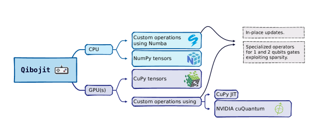
The third backend is qibojit [35], a high-performance simulation backend which combines Just-In-Time (JIT) compilation with the definition of custom operators for state vector manipulation. Here, the action of quantum gates is optimized, by considering matrix properties like sparsity and symmetries, and by avoiding allocating new copies of matrices and vectors, which are instead modified in-place. The qibojit structure is shown in Fig. 2, which shows the specific implementation adopted for CPU and GPU(s) environments.
Multi-threading CPU, GPU and multi-GPU configurations are supported by qibojit. Simulation on CPUs are based on NumPy tensors and accelerated with Numba [56], while for GPU and multi-GPUs executions, we adopt CuPy [57]. For GPUs two different acceleration strategies are implemented. First, we exploit the Cupy’s RawKernel method, thanks to which we can write custom CUDA kernels in C++ and seamlessly import them in Python. The second accelerated simulator is implemented using primitives from NVIDIA cuQuantum [58]. The qibojit backend is the suggested choice for simulating systems with a large number of qubits.
In Section 3.1 of [35], we have conducted benchmarking tests using Qibo on different classical hardware, focusing on significant quantum circuits like Quantum Fourier Transform [59] and Bernstein-Vazirani [60], as the number of qubits increases. These benchmarks also include comparisons of Qibo’s performance with other public quantum computing libraries.
Recognizing the importance of simulation, even as technology advances and the quality of quantum devices improves, we plan to improve Qibo from a simulation perspective. With this in mind, we are working on the development of new backends, supporting multi-node distribution of state vector simulation and, by changing simulation method completely, the construction of a tensor networks [61, 62, 63, 64, 65] backend.
2.3 Quantum hardware support
In the previous section we have shown how Qibo can be used for quantum circuit simulation. Although simulation is a useful tool for testing and profiling quantum algorithms, we are still mainly interested on deploying such algorithms on quantum processors to show the advantages of this technology [66].
Quantum computers can be implemented using several quantum systems, including superconducting circuits [67], trapped ions [68] or neutral atoms [69] among others. In this paper, we focus on superconducting devices, but Qibolab provides an extensible abstraction library to accommodate other quantum technologies, the only precondition is that the experimental setup should be composed by instruments that communicate with each other and the QPUs. As described broadly in Sect. 3.1, it is possible to mirror any experimental configuration by inheriting the Platform class, and deploying the suitable Instruments and Qubits methods, specifying all connections through Channels class. Transmons [70] are one possible implementation of qubits through superconducting devices, which are weakly anharmonic oscillators made using Josephson junctions [71]. To perform measurements, transmons are dispersively coupled to superconducting resonators which are in turn coupled to a microwave transmission line.
Gates are implemented by coupling qubits through microwave drive and flux [70] lines that carry control pulses with precise amplitude and duration.
As shown in Fig. 1, Qibolab includes all the necessary components to construct a backend for the deployment of quantum algorithms on self-hosted quantum processing units (QPUs). The addition of such backend is facilitated by Qibo’s modular layout [36] which enables users to create custom backends with minimum effort. For the particular case of a hardware backend this feature allows us to focus only on low-level components.
Qibolab provides an API to define Pulse objects, able to perform low-level manipulations such as executing a specific sequence of microwave pulses similarly to other libraries [72, 73, 74, 75]. Through this interface it is possible to code easily both experiments and calibration protocols. Such abstraction is quite practical given that instruments may have different definitions for specific waveforms.
Another key element listed in Fig. 1 is the presence of drivers to control and interface Qibo with different instruments. To generate the appropriate microwave pulses needed to perform quantum gates, a common approach is to use Arbitrary Waveform Generators (AWG), digital to analogue (DAC) and analogue to digital converters (ADC) which are nowadays available through Field Programmable Gate Arrays (FPGAs). All these devices usually provide libraries or packages to control them, e.g., Qblox Instruments [76], Qcodes [31] and LabOneQ [74]. Despite such heterogeneity, Qibolab defines a common interface to properly expose package methods required to control QPUs.
Finally Qibolab takes care of all the necessary operations to prepare the execution of quantum circuits on a fully characterized device. Among these, there is a transpilation step of circuits to the native gates supported by the quantum processor and a compilation step to convert these gates to pulses. Sect. 3.3 presents a more precise description of the transpilation step.
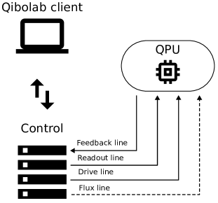
Fig. 3 shows a basic laboratory setup for controlling a QPU. Qibolab is running on a host computer, which communicates, typically via a network protocol, with the control electronics used for pulse generation. These electronics are connected to the QPU via different channels: the readout and feedback channels in a closed loop for measuring the qubit, the drive channel for applying gates and, for flux-tunable qubits, the flux channels for tuning their frequency.
For a more detailed description of the Qibolab backend, we invite the reader to check Sect. 3.1.
2.4 Hardware characterization
While the API provided by Qibolab enables full control over the electronics interacting with the qubits, this alone is not sufficient for operating a quantum computer. This is because the accurate fine-tuning and calibration of control waveform parameters are crucial requirements for quantum hardware to work successfully [77].
Within the Qibo environment, Qibocal [78, 79] offers the necessary tools for calibrating, characterizing, and validating QPUs through a collection of platform and instrument agnostic experiments, or routines.
Thanks to its modular design, it offers routines with different abstraction layers, from low-level characterization routines, including Rabi and Ramsey experiments, to gate-level characterization algorithms [80] such as randomized benchmarking [81, 82, 83, 84, 85].
With Qibocal, it is possible to deploy various calibration and characterization protocols and generate a comprehensive HTML report summarizing the results. Alongside the report, Qibocal also produces the new platform configuration containing the fine-tuned parameters found.
When executing multiple experiments, these parameters can be updated at runtime, allowing for complex routines with real time feedback. This feature unlocks Qibocal’s potential to perform automatized hardware calibration, which will be presented in a future manuscript in preparation [86].
3 Quantum computing drivers
Qibolab provides a unified framework for controlling the different electronics that are needed to operate a quantum computer. To achieve this, we provide software abstractions and patterns that can be followed by a laboratory in order to operate their self-hosted devices. As a use case, we support drivers for multiple commercial instruments, which we use to showcase the library and provide benchmarks in Sec. 4. In the following sections we describe the software abstractions and supported drivers in more detail.
3.1 Software abstractions
Qibolab provides two main interface objects: the Pulse object for defining arbitrary pulses to be played on qubits, and the Platform which is used to execute these pulses on a specific QPU.
Pulses constitute the building blocks of programs that are executed on quantum hardware. They can be used to read the state of a qubit, drive it to change its state, or flux a qubit to change its resonance frequency and probe two-qubit interactions. Qibolab provides pulse objects for each of these operation modes and each Pulse object holds information about the amplitude, frequency, phase, start and duration of the pulse, which are required for the generation of physical pulses. We also provide the functionality to generate waveforms of different shapes, such as Rectangular, Gaussian or DRAG [87].
Real experiments involve playing multiple pulses on different qubits. In Qibolab pulses can be aggregated in a PulseSequence. The Pulse API provides flexibility in scheduling such sequences by specifying when each individual pulse starts in time and allowing overlapping pulses, which are essential for features such as readout multiplexing [88].
Abstract sequences of pulses defined using the Pulse API can be deployed on hardware using a Platform. This core Qibolab object is used to orchestrate the different instruments for qubit control. Each Platform instance corresponds to a specific quantum chip controlled by a specific set of instruments. It allows users to execute a single sequence, a batch of sequences, or perform a sweep, in which one or more pulse parameters are being updated in real-time, within the control instrument. Real-time sweeps or executing sequences in batches, significantly speeds up qubit calibration and characterization procedures.
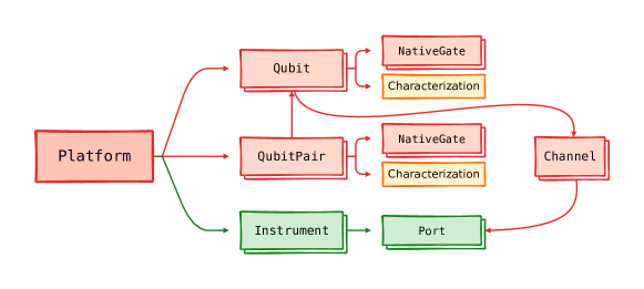
Platform is comprised of different objects as shown in Fig. 4. Qubit objects are representations of the physical qubits. They contain information about physical parameters associated to a qubit that are measured during calibration and characterization [89, 90], such as coherence times and , or the parameters of pulses and sequences needed for single-qubit native gates. Similarly, QubitPair objects contain information about the neighboring pairs of qubits in a chip and the corresponding two-qubit native gates. The topology of the chip is extracted from the available pairs and is used by the transpiler presented in Sec. 3.3.
Platform holds a collection of Instrument objects which contain the low-level drivers for operating the laboratory equipment. The abstract Instrument class contains the methods one needs to implement when interfacing Qibolab to the libraries provided by the instrument’s manufacturers, so that the instrument can be used as part of a larger instrument setup compatible with all functionalities provided by the Qibo framework. Controller is a subclass used by instruments that have arbitrary waveform generators and can play and acquire pulses. Qibolab provides pre-coded driver implementations for several commercial qubit control instruments, as described in Sec. 3.2.
Finally, Channel represents a connection from qubits to instruments. Through the Port object it also implements an interface for controlling instrument parameters. This connection is essential for playing pulses from the instrument port that targets the desired qubit. It also provides a qubit-centric interface for setting instrument parameters, which is useful in calibration routines.
To operate a real QPU, one needs to create a Platform that mirrors the channel and instrument configuration of the lab, following the example shown in Fig. 3. The procedure is outlined in the following steps:
-
1.
instantiate Instrument objects for all instruments in the lab setup;
-
2.
create Channel objects for all connections between instruments and qubits, and map them to the corresponding instrument ports. Auxiliary instruments such as local oscillators can also be mapped to a Channel;
-
3.
create a Qubit object for each qubit;
-
4.
assign all applicable channels (readout, feedback, drive, flux, twpa) to each Qubit. Note that a qubit may not have all of these channels and a channel may be shared among different qubits.
Some parameters involved in this procedure, such as qubit-channel and channel-instrument connections and instrument IP addresses are static, while others, such as the parameters of the pulses that are implementing the native gates, change dynamically during qubit calibration. It is important to distinguish these two categories and handle them separately in the code. Static parameters are typically hard-coded in the Platform generation, while dynamic parameters are loaded as external data. More details on how a custom Platform can be written for a specific lab setup can be found in the online documentation [91]. If the parameters of an existing platform are updated, for example through a calibration routine, it is possible to dump the new parameters on disk using serialization methods [92]. Parameters are uploaded to the respective devices using their specific API, which is abstracted by the Platform interface.
Executing a program on the created Platform is also a multi-step process. Users can write their programs using the Qibolab Pulse API or the Qibo Circuit API. The former is commonly used for low-level applications such as qubit calibration, while the latter is needed for executing quantum algorithms. Execution of circuits involves additional steps. First, they are transpiled (see Sec. 3.3) to new circuits that respect the QPU connectivity and native gates. Secondly, native gates are compiled to pulses following a set of rules which are held in the Compiler object of the Qibolab backend. Once a PulseSequence is available, either directly or from compilation of a circuit, it can be deployed using a Platform. The Platform will send each pulse to the appropriate instrument ports and acquire feedback associated to measurements. This will be returned to the user according to the specified format. The Qibolab port is an internal abstraction, that takes care of bridging the gap between the Qibolab compiled PulseSequence and the output format to the specific input and output defined by each device. Available formats are classified shots (0 or 1), integrated and demodulated voltage signals, or raw waveform signals. All formats can be obtained as single shots or averaged. More details on the different result formats can be found in the online documentation [93].
3.2 Supported drivers
Version 0.1.0 of the Qibolab package provides extensive support for various devices used in quantum hardware control. Specifically, it supports devices developed by Qblox [94], Quantum Machines [95], Zurich Instruments [96], as well as RFSoC (Radio Frequency System on Chip) FPGAs (Field Programmable Gate Arrays) supported by the Qick project [97] and by Qibosoq [98]. Each of these devices possesses distinct requirements and operational methods, necessitating meticulous attention to ensure seamless control through a unified interface. In more detail:
- Qblox
-
the Qblox Instruments cluster [99] where we tested Qibolab is composed of several modular devices controlled as one. The Qblox Cluster is the scalable 19” rack instrument that can be configured with a combination of up to 20 modules that can control and readout qubits over a wide frequency range (up to 18.5 GHz). Our setup to control 5 superconducting flux tunable qubits without coupler mediated interactions is composed by:
- QRM-RF
-
two Qubit Readout Modules [100] with one input channel and one output channel in the radio-frequency regime and 2 digital markers. The module provides all necessary capabilities for qubit readout without external up or down conversion for signals in the range of 2-18.5GHz.
- QCM-RF
-
three Qubit Control Modules [101] with two drive channels per module dedicated to the qubit control using parametrized pulses, that allows the user to control up to 5 qubits.
- QCM
-
two QCM modules [102] to control the DC voltage applied to the flux channels of the qubits and generate the flux pulses needed to implement two-qubit gates. The dynamic output range of the DACs (digital-to-analog converters) of the Quantum Control Modules is 5 Vpp, the difference between the highest and the lowest voltage values in a AC signal, with a 1Gsps sampling rate.
The system synchronization of the signals between the modules is made by the Qblox Cluster using SYNQ [103] protocols. The high-level interface for the devices comes from Qblox Instruments [76] and Qcodes [104] Python-based libraries, and the low-level communication with the sequencers is made using assembly code (Q1ASM) [105]. This setup allows control of 5+ flux tunable superconducting qubits.
- Quantum Machines
-
Qibolab has been tested in controlling a cluster of nine OPX+ controllers [106], and communicate with an all-to-all connectivity to support fast feedback operations between any pair of controllers. The synchronization and clock distribution is handled by OPT devices. Each OPX+ controller has ten analogue output ports, ten digital output ports and two input ports, making the cluster capable of controlling 25+ flux tunable capacitively coupled qubits. The main disadvantage of our OPX+ controllers, compared to other instruments used in this work, is that the IQ mixing and upconversion are not taken care internally and there is small bandwidth for the intermediate frequency (400MHz) and output voltage (0.5V). Due to these limitations, additional external instruments including local oscillators, mixers and sometimes amplifiers are needed to successfully drive and flux qubits. The Qibolab driver is controlling the whole cluster as a single instrument using the QUA library [75]. This library exposes many low-level operations to Python via an intuitive but rich set of commands, which expands beyond simple pulse scheduling and includes conditional logic, loops and complex mathematical operations.
- Zurich Instruments
-
the Zurich Instruments cluster where we tested Qibolab is composed of several modular devices controlled as one.
- SHFQC
-
a single SHFQC [107], that can control the drive and readout of up to 6 superconducting qubits connected to the same readout probe. The IQ mixing and upconversion are taken care of internally by using a proprietary cleaner signal upconversion and downconversion scheme [108] with an instantaneous bandwidth around 1.2 GHz without the need for calibration. They also provide an output voltage of 2 Vpp.
- HDAWG
-
two HDAWGs [109] to provide up to 8 DC-coupled single-ended analogue output channels each to control the flux pulses required to interact with qubits and couplers. Up to 5 Vpp output voltage.
- PQSC
-
A single PQSC [110], to synchronize the previous devices via the low-latency, real-time communication link ZSync. The PQSC comes with 18 ZSync ports to distribute the system clock and synchronize the instruments. Furthermore, the links provide a bidirectional data interface to send qubit readout results to the PQSC for central processing and send trigger signals to the slave instruments for feedback.
The high-level interface for the devices comes from the Python-based LabOneQ library [74]. This setup allows control of 5+ flux tunable superconducting qubits with tunable coupler-mediated interactions.
- RFSoCs
-
the RFSoCs supported by Qibolab currently include the RFSoC4x2 [111], the ZCU111 [112], and the ZCU216 [113] manufactured by Xilinx. These FPGAs possess a unique feature of offering direct RF synthesis capability up to GHz. This simplifies the experimental setup by eliminating the need for additional local oscillators and IQ mixers. To interact with the Qick firmware, the driver relies on a server that runs on board called Qibosoq. Both the Qibosoq server and the Qick firmware are open source, reducing costs for setting up a new laboratory. However, it is important to note that these boards have limitations in terms of the number of qubits they can control, can be challenging to synchronize in multi-board setups and, in general, the software supports less features than other devices.
In addition to the devices responsible for synthesizing pulses to control the qubits and acquiring signals for measurements, a comprehensive quantum control system relies on additional devices. Among these, local oscillators play a crucial role in up and down converting microwave signals for some of our devices and pumping the TWPAs. Integrating local oscillators within the same framework is essential since they need to be calibrated and turned on and off during the control process. Qibolab facilitates seamless integration of these devices and includes drivers for Erasynth and Rohde&Schwarz local oscillators in version 0.1.0.
| Device | Firmware | Software | |
|---|---|---|---|
| Qblox | 0.4.0 | qblox-instruments 0.9.0 | |
| QM | QOP213 | qm-qua 1.1.1 | |
| Zurich | Latest (July 2023)111See appendix [6.1] | LabOneQ 2.7.0 | |
| RFSoCs | Qick 0.2.135 | Qibosoq 0.0.3 | |
| Erasynth++ | - | - | |
|
- | QCoDeS 0.37.0 |
An outline of the supported instruments is presented in Table 1, while in Table 2 we present an overview of the primary features supported by the drivers included with Qibolab version 0.1.0. It is important to note that while some limitations and missing features are currently present, they are not necessarily inherent to the devices themselves and will be addressed in future versions of Qibolab.
| Feature | RFSoCs | Qblox | QM | Zhinst |
|---|---|---|---|---|
| Arbitrary pulse sequences | \usym1F5F8 | \usym1F5F8 | \usym1F5F8 | \usym1F5F8 |
| Arbitrary waveforms | \usym1F5F8 | \usym1F5F8 | \usym1F5F8 | \usym1F5F8222Sweeper capabilities may be reduced by using arbitrary pulses instead of driver defined ones. |
| Multiplexed readout | \usym1F5F8 | \usym1F5F8 | \usym1F5F8 | \usym1F5F8 |
| Hardware classification | \usym2613 | \usym1F5F8 | \usym1F5F8 | \usym1F5F8 |
| Fast reset | \usym1F4BB | \usym1F4BB | \usym1F4BB | \usym1F4BB |
| Device simulation | \usym2613 | \usym2613 | \usym1F5F8 | \usym1F4BB |
| RTS frequency | \usym1F5F8333RTS on the frequency of readout pulses not supported. | \usym1F5F8 | \usym1F5F8 | \usym1F5F8 |
| RTS amplitude | \usym1F5F8 | \usym1F5F8 | \usym1F5F8 | \usym1F5F8 |
| RTS duration | \usym2613 | \usym1F5F8 | \usym1F5F8 | \usym1F5F8 |
| RTS start | \usym1F5F8 | \usym1F5F8 | \usym1F5F8 | \usym1F5F8 |
| RTS relative phase | \usym1F5F8 | \usym1F5F8 | \usym1F5F8 | \usym1F5F8 |
| RTS 2D any combination | \usym1F5F8 | \usym1F5F8 | \usym1F5F8 | \usym1F5F8 |
| Sequence unrolling | \usym1F4BB | \usym1F4BB | \usym1F4BB | \usym1F4BB |
| Hardware averaging | \usym1F5F8 | \usym1F5F8 | \usym1F5F8 | \usym1F5F8 |
| Singleshot (No Averaging) | \usym1F5F8 | \usym1F5F8 | \usym1F5F8 | \usym1F5F8 |
| Integrated acquisition | \usym1F5F8 | \usym1F5F8 | \usym1F5F8 | \usym1F5F8 |
| Classified acquisition | \usym1F5F8 | \usym1F5F8 | \usym1F5F8 | \usym1F5F8 |
| Raw waveform acquisition | \usym1F5F8 | \usym1F5F8 | \usym1F5F8 | \usym1F5F8 |
The following is a description of the features presented in Table 2.
- Arbitrary pulse sequences
-
the capability of executing arbitrary pulse sequences defined in Qibolab, which is a fundamental requirement of a driver. This feature is not related to the execution of pulses with arbitrary waveform shapes.
- Arbitrary waveforms
-
the capability of executing pulse waveforms of arbitrary shape. For drivers that do not support this feature, rectangular, Gaussian and DRAG waveforms can still be synthesized.
- Multiplexed readout
-
allows playing and acquiring multiple multiplexed pulses through the same line. It is particularly useful for multi-qubit chips where the readout line is commonly shared among multiple qubits.
- Hardware classification
-
the capability of doing single shot measurement classification during the execution of a pulse sequence.
- Fast reset
-
the capability of actively resetting the state of a qubit to zero after a measurement. This feature requires hardware classification and enables faster executions of repeated pulse sequences.
- Device simulation
-
the possibility of simulating in advance the pulses to be executed, without directly using quantum hardware.
- RTS frequency
-
RTS (Real Time Sweeper) refers to the capability of executing a pulse sequence multiple times with different values of, in this case, the frequency of a pulse. This feature facilitates faster qubit characterization and experiments.
- RTS amplitude
-
real-time sweeping of the amplitude of a pulse.
- RTS duration
-
real-time sweeping of the duration of a pulse.
- RTS start
-
real-time sweeping of the start time of a pulse.
- RTS relative phase
-
real-time sweeping of the relative phase of a pulse.
- RTS 2D
-
the capability of combining two RTS scans on different parameters.
- Sequence unrolling
-
the capability of unrolling several smaller subsequences into a longer single sequence as in loop unrolling. It aims to decrease the overall time spent on compilation and communication steps by reducing its amount from once every subsequence to once every unrolled sequence.
- Hardware averaging
-
the capability of repeating the same experiment multiple times and obtain, directly from the device, averaged results.
- Singleshot (No Averaging)
-
the capability of obtaining from the devices all the non-averaged results.
- Integrated acquisition
-
the capability of acquiring complex signals [114] with ”in-phase” and ”quadrature” (IQ) components demodulated and integrated for the measuring time.
- Classified acquisition
-
the capability of performing 0-1 state classification after the integrated acquisition.
- Raw waveform acquisition
-
the capability of acquiring non-integrated IQ waveform values.
3.3 Transpiler
Logical quantum circuits for quantum algorithms are hardware agnostic. Usually an all-to-all qubit connectivity is assumed while most current hardware only allows the execution of two-qubit gates on a restricted subset of qubit pairs. Moreover, quantum devices are restricted to executing a subset of gates, referred to as native [115]. This means that, in order to execute circuits on a real quantum chip, they must be transformed into an equivalent, hardware specific, circuit. The transformation of the circuit is carried out by the transpiler through the resolution of two key steps: connectivity matching [116] and native gates decomposition [117]. In order to execute a gate between two qubits that are not directly connected SWAP gates [118] are required. This procedure is called routing. As on NISQ devices two-qubit gates are a large source of noise, this procedure generates an overall noisier circuit. Therefore, the goal of an efficient routing algorithm is to minimize the number of SWAP gates introduced. An important step to ease the connectivity problem, is finding an optimal initial mapping between logical and physical qubits. This step is called placement. The native gates decomposition in the transpiling procedure is performed by the unroller. An optimal decomposition uses the least amount of two-qubit native gates. It is also possible to reduce the number of gates of the resulting circuit by exploiting commutation relations [119], KAK decomposition [120] or machine learning techniques [121].
Qibolab implements a built-in transpiler with customizable options for each step. The main algorithms that can be used at each transpiler step are reported below with a short description. The initial placement can be found with one of the following procedures:
-
•
Trivial: logical-physical qubit mapping is an identity.
-
•
Custom: custom logical-physical qubit mapping.
-
•
Random greedy: the best mapping is found within a set of random layouts based on a greedy policy.
-
•
Subgraph isomorphism: the initial mapping is the one that guarantees the execution of most gates at the beginning of the circuit without introducing any SWAP.
-
•
Reverse traversal: this technique uses one or more reverse routing passes to find an optimal mapping by starting from a trivial layout [122].
The routing problem can be solved with the following algorithms:
-
•
Shortest paths: when unconnected logical qubits have to interact, they are moved on the chip on the shortest path connecting them. When multiple shortest paths are present, the one that also matches the largest number of the following two-qubit gates is chosen.
-
•
SABRE [122]: this heuristic routing technique uses a customizable cost function to add SWAP gates that reduce the distance between unconnected qubits involved in two-qubit gates.
Qibolab unroller applies recursively a set of hard-coded gates decompositions in order to translate any gate into single and two-qubit native gates. Single qubit gates are translated into U3, RX, RZ, X and Z gates. It is possible to fuse multiple single qubit gates acting on the same qubit into a single U3 gate. For the two-qubit native gates it is possible to use CZ and/or iSWAP. When both CZ and iSWAP gates are available the chosen decomposition is the one that minimizes the use of two-qubit gates.
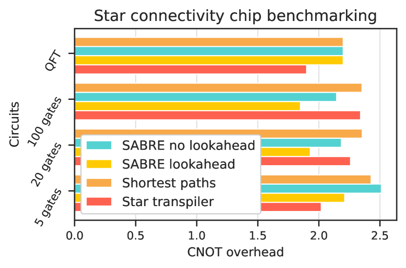
The benchmarking of a full transpiling pipeline can be complex, as the results may vary in different chip architectures and a trade-off between performance and execution time needs to be taken into account. We remand the general benchmarking problem to the specific literature [123] and we focus on a more specific use-case. Fig. 5 reports the performance of the routing pass algorithms implemented in Qibolab on a five qubit chip with a star connectivity. In this kind of chip five qubits are arranged with a central qubit connected to all the remaining four qubits. The algorithm performance has been evaluated as the CNOT overhead. That is the number of CNOT gates on the routed circuit divided by the number of CNOT gates in the original circuit. The algorithm performance has been tested on five qubit circuits composed of 10, 20 and 100 CNOT gates, taking an average over 50 random circuits. Moreover, we have tested the algorithms on a structured circuit: the five qubits QFT. The SABRE algorithm has been tested with and without the lookahead. The results have been compared with transpiler designed for that connectivity (star transpiler) that swaps the central qubit in the chip based on the successive gate. All the routing algorithms have been tested starting from an initial trivial layout except for the star transpiler that has a built-it placer, this explains the better performance of this algorithm on short circuits. Fig. 5 shows that SABRE with a lookahead reaches the best performance on the star connectivity chip. The execution time on this simple case is not significant as all algorithms perform in a fraction of second even for the longer circuits. However, other tests has shown that the scalability of SABRE is better than shortest paths as the number of possible shortest paths increases drastically with the number of qubits in highly connected chips. In summary, Qibolab transpiler shows good performance in making abstract quantum circuits executable on small NISQ devices. In the future we aim at developing new efficient and scalable algorithms for the next generation quantum chips with a high number of qubits.
4 Application results
4.1 Cross-platform benchmark
 |
 |
 |
 |
 |
 |
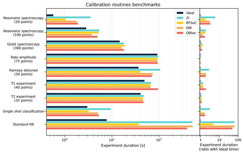
In this section, we present the results of a speed benchmark conducted using Qibolab. The benchmark involved various experiments deployed on the different control devices currently supported by the drivers implemented in Qibolab.
By utilizing Qibolab, assessing the performance and efficiency of each control device becomes a straightforward process, since all devices are exposed through the same interface. The results obtained not only offer valuable insights into the speed of the different instruments, offering data that can help researchers and developers to make informed decisions, but also demonstrate the comprehensive support these devices receive within Qibolab.
The experiments chosen for this benchmark represent the minimal set of routines required for the calibration of a single qubit. They also offer a view of the different execution modes supported by Qibolab: in particular the Single shot classification experiment executes fixed pulses sequences, while the Spectroscopies perform different sweeps over pulse parameters.
In Fig. 6 we present a comparison of execution times for different qubit calibration routines executed using different electronics. Additional details for each routine are provided in the Appendix 6.2. The black bar in this plot provides the time required for each routine, which, in most cases, is calculated as
| (1) |
where is the duration of the whole pulse sequence in the -th point of the sweep, the time we wait for the qubit to relax to its ground state between experiments, the number of shots in each experiment and the sum runs over all points in the sweep. The time denotes how long the qubit is really used during an experiment and provides the baseline for our benchmark. Real executions, shown with a different color for each instrument setup, are longer than , due to overhead coming from compilations and communication to the instruments. After profiling the code, we observe that the overhead coming from the Qibolab backend, , is negligible compared to that of the control instruments, . Therefore, we can approximate the real execution time as
| (2) |
There is a decisive factor regarding the performance of routines that involve sweeps. That is, whether the sweeps run in real-time in the processors embedded in the control electronics or the host computer. The latter approach requires a greater number of communication steps between control electronics and host and typically the programs need to be recompiled multiple times resulting in significant overhead. This can be seen in the Ramsey detuned and standard Randomized Benchmarking (RB) experiments, for which real time sweepers have not been implemented yet, resulting to a significant overhead over the ideal time. Randomized Benchmarking experiments, unlike the rest of routines used here, involve playing multiple random sequences instead of sweeping parameters and their performance is expected to increase when sequence unrolling will be implemented.
The second point affecting performance is the communication with the host computer. This usually involves two steps, the actual communication via network (ethernet) and a compilation step happening on the instrument side. We observe that RFSoC boards controlled using Qibosoq have an advantage in this, particularly from Ramsey detuned and Single shot classification where real-time sweepers are not used. This advantage may be due to the simplicity of our RFSoC configuration, which consists of a single board, in contrast to the other systems which are part of clusters with more controllers. More investigation is needed to confirm this point. As expected, the rest of electronics behave similarly in all performed benchmarks.
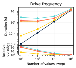
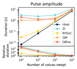
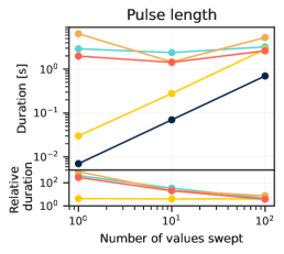
In Fig. 7 we demonstrate how execution time of different sweeps scales with the number of points used in the sweep. Similarly to above, we see that RFSoC is faster for short sweeps, due to smaller communication and compilation overhead, however the difference diminishes when we cross 100 points. Other instruments show similar behavior in most cases. Qick does not support real-time sweeping of readout frequency and pulse length, therefore these sweepers are slower when compared to other instruments for more than 100 points. Real-time sweepers are used in all cases presented in this plot, except in Circuits. We are currently implementing sequence unrolling methods, which will allow executing batches of circuits, reducing the communication overhead and thus improving runtime.
The code used for all benchmarks presented in this section is provided in a public repository [124].
4.2 Standard randomized benchmarking

The commonly used technique for assessing the accuracy of single qubit gate implementations is standard randomized benchmarking (RB) [81, 82, 83, 84, 85] with the Clifford group (see, e.g., Ref. [80] for a review). The RB protocol performs random sequences of Clifford unitaries of different lengths on a single qubit. Every sequence is concluded with the unitary gate that restores the initial state before measuring the qubit. In the absence of imperfections, the measurement, thus, is expected to be classified as (the initial state) with probability independent of the sequence or its length. Single qubit gate fidelities are defined as functions of the decay parameter of this average survival probability with the sequence length.
RB allows us to holistically test the entire software stack together with the quantum hardware. We define the RB protocol with the Circuit API of Qibo, using U3, RX, RY and RZ gates. Executing them with the Qibolab backend involves transpilation to native gates and compilation to PulseSequence objects that are then executed by a Platform. An example of an RB experiment on a -qubit IQM chip controlled using Qibolab’s Zurich Instruments drivers is depicted in Fig. 8.
4.3 CHSH Experiment
A quantum software solution should allow for the development and deployment of quantum experiments at different levels of abstraction and complexity. In order to showcase this, we prepare an experiment to measure the CHSH inequality [125] between two qubits by building the circuit using three distinct methods allowed by Qibo and Qibolab. Namely, one can build experiments by directly accessing the arbitrary pulse sequences of Qibolab, use the native gate interactions through Qibo, or use logical gate operations and rely on the transpiler for the decomposition. In addition, we incorporate a layer of Readout Error Mitigation [42] that is executed on hardware before the experiment takes place. This type of control is only possible with framework aware of all layers of abstraction such as Qibo.
The CHSH inequality was originally conceived in order to disprove a local hidden-variable description of quantum mechanics and used to prove Bell’s theorem [126]. The protocol consists of preparing a maximally entangled two-qubit state, and performing a simultaneous measurement on both qubits, with two possible measurement settings. Crucially, a qubit can be measured in two perpendicular basis (e.g. , ), and the measurement settings of both qubits have a relative angle . Then, the combination of the resulting expectation values
| (3) |
should be if there is a local hidden-variable theory of quantum mechanics, but go beyond, up to , if not.
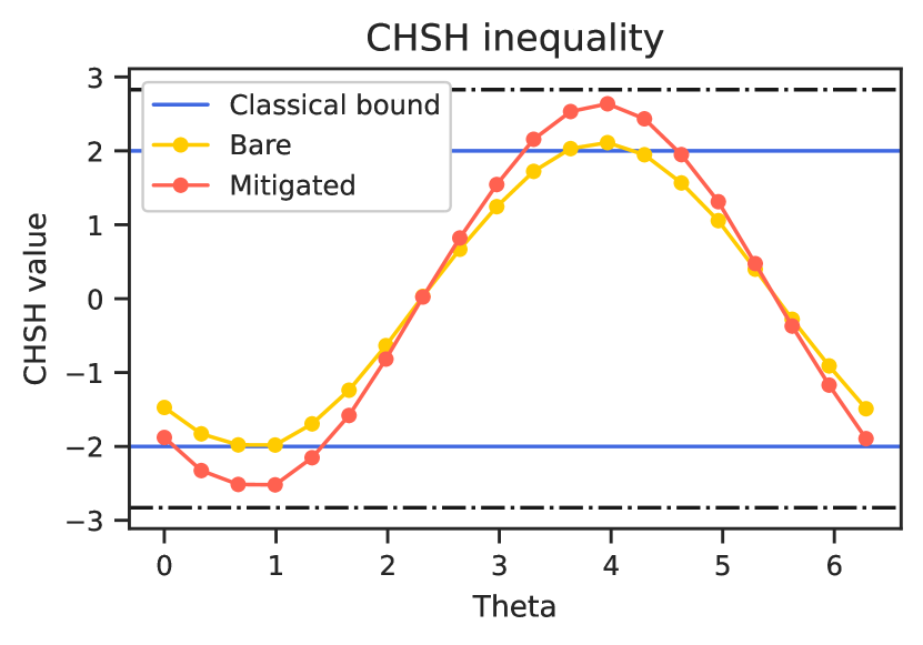
In this context, the CHSH experiment is used as validation of both the specifications of the machine and control electronics. Far from disproving local realism, we use this procedure to verify that the control of our chip is precise enough to violate the classical bound. We show in Fig. 9 the results of a CHSH experiment on two connected qubits of a 5-qubit QuantWare chip controlled using Qibolab’s Qblox drivers for different angles of the measurement setting. The bare values of the CHSH barely cross above the classical bound. However, when readout error mitigation is applied, the values confidently cross above . We infer from this figure that the most destructive source of error was in the readout of the measurement pulse, rather than on the control of the two-qubit gate pulse.
4.4 Full-stack quantum machine learning
Developing QML algorithms [127, 128, 129] is particularly challenging in the NISQ era [53]. Noise and long execution times are two of the most limiting problems while deploying a Variational Quantum Algorithm [130, 131] on a real quantum device. In this context, it is relevant to study how the different levels of computation, from the high-level coding of the algorithm to the low-level deployment on the real qubits, impact the results obtained on simple regression or classification tasks. For this reason, Qibo has become the perfect environment to study both hybdrid [132, 133, 48, 134] and full-stack [135] QML algorithms.
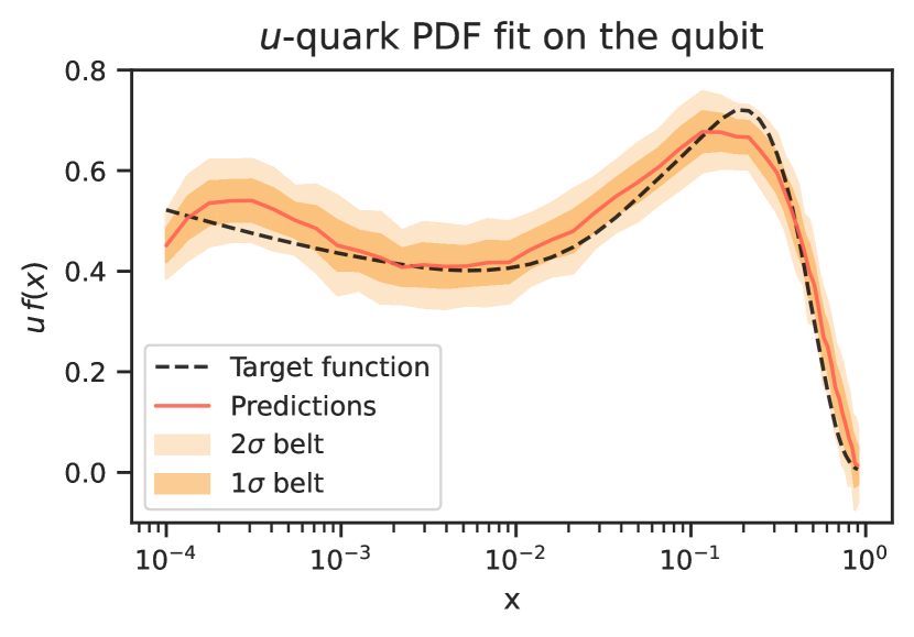
We define a QML model by building a Variational Quantum Circuit (VQC), in whose rotational gates we encode the -quark Parton Distribution Function (PDF) data picked up from the NNPDF4.0 [136] PDF grid. In particular, we consider as input data values of the momentum fraction , sampled logarithmically from the range . We use the model presented in [132], in which the embedding of the values is implemented following a data re-uploading ansatz [137].
The optimization strategy is then implemented by minimizing a target Mean-Squared Error loss function with respect to the model’s parameters. We select a hardware-compatible Adam [138] optimizer, in which we calculate the derivatives of the circuit using the Parameter Shift Rule [129, 139, 135]. Once obtained the optimized parameters vector , we inject them into the circuit and repeat the predictions times. With the mean and the standard deviation of these evaluations we calculate our final estimates and their errors. Finally, we quantify the accuracy of the model by computing the following test statistics:
| (4) |
where is the target PDF value provided by NNPDF4.0 and is the mean of the predicted values for a fixed data .
We perform an initial training in exact simulation using Qibo, followed by stochastic Adam descent iterations on a single superconducting qubit controlled by RFSoC via Qibosoq [98]. After completing the training, those corresponding to the epoch in which we recorded the lowest loss function value are chosen as the final parameters. Each prediction during the gradient descent is obtained by executing the circuit times and we set a learning rate equal to . Adam’s parameters are set to be , and .
In Fig. 10 we show the obtained results after repeating the PDF predictions times for each data: the solid orange line is drawn using the means of the predictions , while the two confidence intervals are obtained one and two standard deviations from the means. The test statistic value presented in Eq. (4) and calculated with our predictions is . These results show the entire ecosystem can be used to successfully fit the target function even without any error mitigation technique.
5 Outlook
In this paper we extend the Qibo quantum computing middleware framework by introducing Qibolab, an open-source software library for quantum hardware control. Qibo is designed as a full-stack software framework which provides primitives to define circuit-based quantum algorithms through custom backends, i.e. dedicated plugin software libraries which deploy algorithms on specific hardware. The release of Qibolab unlocks Qibo’s potential to execute quantum algorithms on hardware platforms and therefore grant to research institutions and laboratories the possibility to operate self-hosted quantum hardware platforms easily.
We have described the current status of the project structure with the major features implemented in release 0.1.0. The software abstractions, supported drivers and transpiler are at the stage of allowing applications related to cross-platform control instrument performance benchmarks through arbitrary pulse control and physics experiments based on the quantum circuit representation.
Furthermore, we have demonstrated successfully three practical-cases in which Qibolab could be useful for quantum technology research: randomized benchmarking, validation algorithms for qubit entanglement (CHSH experiment) and quantum machine learning applications. Therefore, circuit-based models available in Qibo can be deployed seamlessly on quantum hardware through Qibolab.
In the future releases of Qibolab, we plan to extend its capabilities by interfacing new drivers from more commercial and open-source control system vendors. Thanks to the design of the library, we have the possibility to adapt and scale the API for new electronics including large-scale systems for real-time acquisition and error correction. On the other hand, in this paper we have focused on superconducting chips due to its availability in our affiliated institution labs, however we plan to extend Qibolab to other quantum technologies such as trapped ions, neutral atoms and photonics among others. In fact, there are multiple software similarities among these technologies, e.g. for trapped ions we can already define in Qibolab a custom platform which allocates the relevant pulse sequence to modulate optical lasers with its native gates representation for unitary gate preparation. We plan to have access to this and other quantum hardware technologies in the next years through research collaborations and extend Qibolab accordingly. Finally, we believe that with the inclusion of Qibolab, Qibo has grown into a powerful tool for the quantum computing community, by reducing the effort of software development for researchers in simulation, hardware calibration and operation.
The code implementing the Qibolab module is available at:
References
- Brun and Rademakers [1997] R. Brun and F. Rademakers, Nuclear Instruments and Methods in Physics Research Section A: Accelerators, Spectrometers, Detectors and Associated Equipment 389, 81 (1997), new Computing Techniques in Physics Research V.
- Alwall et al. [2014] J. Alwall, R. Frederix, S. Frixione, V. Hirschi, F. Maltoni, O. Mattelaer, H.-S. Shao, T. Stelzer, P. Torrielli, and M. Zaro, Journal of High Energy Physics 2014, 10.1007/jhep07(2014)079 (2014).
- Abadi et al. [2015] M. Abadi, A. Agarwal, P. Barham, E. Brevdo, Z. Chen, C. Citro, G. S. Corrado, A. Davis, J. Dean, M. Devin, S. Ghemawat, I. Goodfellow, A. Harp, G. Irving, M. Isard, Y. Jia, R. Jozefowicz, L. Kaiser, M. Kudlur, J. Levenberg, D. Mané, R. Monga, S. Moore, D. Murray, C. Olah, M. Schuster, J. Shlens, B. Steiner, I. Sutskever, K. Talwar, P. Tucker, V. Vanhoucke, V. Vasudevan, F. Viégas, O. Vinyals, P. Warden, M. Wattenberg, M. Wicke, Y. Yu, and X. Zheng, TensorFlow: Large-scale machine learning on heterogeneous systems (2015), software available from tensorflow.org.
- cir [2018] Cirq, a python framework for creating, editing, and invoking Noisy Intermediate Scale Quantum (NISQ) circuits (2018).
- Broughton and et al. [2020] M. Broughton and et al., Tensorflow quantum: A software framework for quantum machine learning (2020).
- Abraham and et al. [2019] H. Abraham and et al., Qiskit: An open-source framework for quantum computing (2019).
- Smith et al. [2016] R. S. Smith, M. J. Curtis, and W. J. Zeng, A practical quantum instruction set architecture (2016).
- Guerreschi et al. [2020] G. G. Guerreschi, J. Hogaboam, F. Baruffa, and N. P. D. Sawaya, Quantum Science and Technology 5, pp. 034007 (2020).
- Kelly [2018] A. Kelly, Simulating quantum computers using opencl (2018).
- The Qulacs developers [2018] The Qulacs developers, Qulacs (2018).
- Jones et al. [2019] T. Jones, A. Brown, I. Bush, and S. C. Benjamin, Scientific Reports 9, 10.1038/s41598-019-47174-9 (2019).
- Zhang et al. [2015] P. Zhang, J. Yuan, and X. Lu, in Algorithms and Architectures for Parallel Processing, edited by G. Wang, A. Zomaya, G. Martinez, and K. Li (Springer International Publishing, Cham, 2015) pp. 241–256.
- Steiger et al. [2018] D. S. Steiger, T. Häner, and M. Troyer, Quantum 2, 49 (2018).
- qsh [2017] The Q# programming language (2017).
- Zulehner and Wille [2017] A. Zulehner and R. Wille, Advanced simulation of quantum computations (2017).
- Pednault and et al. [2017] E. Pednault and et al., Pareto-efficient quantum circuit simulation using tensor contraction deferral (2017).
- Bravyi and Gosset [2016] S. Bravyi and D. Gosset, Physical Review Letters 116, pp. 250501 (2016).
- De Raedt and et al. [2007] K. De Raedt and et al., Computer Physics Communications 176, pp. 121 (2007).
- Fried and et al. [2018] E. S. Fried and et al., PLOS ONE 13, e0208510 (2018).
- Villalonga and et al. [2019] B. Villalonga and et al., npj Quantum Information 5, 10.1038/s41534-019-0196-1 (2019).
- Luo et al. [2019] X.-Z. Luo, J.-G. Liu, P. Zhang, and L. Wang, Yao.jl: Extensible, efficient framework for quantum algorithm design (2019), arXiv:1912.10877 [quant-ph] .
- Bergholm and et al. [2018] V. Bergholm and et al., Pennylane: Automatic differentiation of hybrid quantum-classical computations (2018), arXiv:1811.04968 [quant-ph] .
- Doi and et al. [2019] J. Doi and et al., in Proceedings of the 16th ACM International Conference on Computing Frontiers, CF ’19 (Association for Computing Machinery, New York, NY, USA, 2019) p. 85–93.
- Möller and Schalkers [2020] M. Möller and M. Schalkers, in Computational Science – ICCS 2020, edited by V. V. Krzhizhanovskaya, G. Závodszky, M. H. Lees, J. J. Dongarra, P. M. A. Sloot, S. Brissos, and J. Teixeira (Springer International Publishing, Cham, 2020) pp. 451–464.
- Jones and Benjamin [2020] T. Jones and S. Benjamin, Quantum Science and Technology 5, 034012 (2020).
- Chen and et al. [2018] Z.-Y. Chen and et al., Science Bulletin 63, pp. 964–971 (2018).
- Bian et al. [2020] H. Bian, J. Huang, R. Dong, Y. Guo, and X. Wang, in Algorithms and Architectures for Parallel Processing, edited by M. Qiu (Springer International Publishing, 2020) pp. 111–125.
- Meyerov et al. [2020] I. Meyerov, A. Liniov, M. Ivanchenko, and S. Denisov, Simulating quantum dynamics: Evolution of algorithms in the hpc context (2020), arXiv:2005.04681 [quant-ph] .
- Moueddene et al. [2020] A. A. Moueddene, N. Khammassi, K. Bertels, and C. G. Almudever, Realistic simulation of quantum computation using unitary and measurement channels (2020), arXiv:2005.06337 [quant-ph] .
- Wang and et al. [2020] Z. Wang and et al., A quantum circuit simulator and its applications on sunway taihulight supercomputer (2020).
- Nielsen et al. [2024] J. H. Nielsen, M. Astafev, W. H. Nielsen, D. Vogel, lakhotiaharshit, A. Johnson, A. Hardal, Akshita, sohail chatoor, F. Bonabi, Liang, G. Ungaretti, S. Pauka, T. Morgan, Adriaan, P. Eendebak, B. Nijholt, qSaevar, P. Eendebak, S. Droege, Samantha, J. Darulova, R. van Gulik, N. Pearson, ThorvaldLarsen, and A. Corna, Qcodes/qcodes: Qcodes 0.43.0 (2024).
- Rol et al. [2016] M. Rol, C. Dickel, S.Asaad, N. Langford, C. Bultink, R. Sagastizabal, N. Langford, G. de Lange, X. Fu, S. de Jong, F. Luthi, and W. Vlothuizen, DiCarloLab-Delft/PycQED_py3: Initial public release (2016).
- Keysight [2022] Keysight, Labber, https://www.keysight.com/us/en/lib/software-detail/instrument-firmware-software/labber-3113052.html (2022).
- Efthymiou et al. [2021] S. Efthymiou, S. Ramos-Calderer, C. Bravo-Prieto, A. Pérez-Salinas, a.-M. . í, . Diego Garcí, A. Garcia-Saez, J. I. Latorre, and S. Carrazza, Quantum Science and Technology 7, 015018 (2021).
- Efthymiou et al. [2022] S. Efthymiou, M. Lazzarin, A. Pasquale, and S. Carrazza, Quantum 6, 814 (2022).
- Carrazza et al. [2023] S. Carrazza, S. Efthymiou, M. Lazzarin, and A. Pasquale, Journal of Physics: Conference Series 2438, 012148 (2023).
- Efthymiou et al. [2023a] S. Efthymiou et al., qiboteam/qibo: Qibo 0.1.12 (2023a).
- Efthymiou et al. [2023b] S. Efthymiou et al., qiboteam/qibolab: Qibolab 0.0.2 (2023b).
- Preskill [2018a] J. Preskill, (2018a).
- He et al. [2020] A. He, B. Nachman, W. A. de Jong, and C. W. Bauer, Phys. Rev. A 102, 012426 (2020).
- Sopena et al. [2021] A. Sopena, M. H. Gordon, G. Sierra, and E. López, Quantum Science and Technology 6, 045003 (2021).
- van den Berg et al. [2022] E. van den Berg, Z. K. Minev, and K. Temme, Physical Review A 105, 10.1103/physreva.105.032620 (2022).
- Coppersmith [2002a] D. Coppersmith, An approximate fourier transform useful in quantum factoring (2002a).
- Peruzzo and et al. [2014] A. Peruzzo and et al., Nature communications 5, pp. 4213 (2014).
- Garcia-Saez and Latorre [2018] A. Garcia-Saez and J. I. Latorre, Addressing hard classical problems with adiabatically assisted variational quantum eigensolvers (2018).
- Farhi et al. [2014] E. Farhi, J. Goldstone, and S. Gutmann, A quantum approximate optimization algorithm (2014).
- Magann et al. [2022] A. B. Magann, K. M. Rudinger, M. D. Grace, and M. Sarovar, Physical Review Letters 129, 10.1103/physrevlett.129.250502 (2022).
- Bravo-Prieto et al. [2022] C. Bravo-Prieto, J. Baglio, M. Cè, A. Francis, D. M. Grabowska, and S. Carrazza, Quantum 6, 777 (2022).
- Grover [1996] L. K. Grover, A fast quantum mechanical algorithm for database search (1996).
- Hadfield et al. [2019] S. Hadfield, Z. Wang, B. O. Gorman, E. Rieffel, D. Venturelli, and R. Biswas, Algorithms 12, 34 (2019).
- Farhi et al. [2000] E. Farhi, J. Goldstone, S. Gutmann, and M. Sipser, Quantum computation by adiabatic evolution (2000).
- [52] Qibo: API documentation examples, https://qibo.science/qibo/stable/api-reference/index.html.
- Preskill [2018b] J. Preskill, Quantum 2, 79 (2018b).
- Oliphant [2006] T. E. Oliphant, Guide to NumPy (Trelgol, 2006).
- Rumelhart et al. [1986] D. E. Rumelhart, G. E. Hinton, and R. J. Williams, Nature 323, 533 (1986).
- Lam et al. [2015] S. K. Lam, A. Pitrou, and S. Seibert, in Proceedings of the Second Workshop on the LLVM Compiler Infrastructure in HPC (2015) pp. 1–6.
- Okuta et al. [2017] R. Okuta, Y. Unno, D. Nishino, S. Hido, and C. Loomis, in Proceedings of Workshop on Machine Learning Systems (LearningSys) in The Thirty-first Annual Conference on Neural Information Processing Systems (NIPS) (2017).
- cuQuantum development team [2023] T. cuQuantum development team, cuquantum (2023), if you use this software, please cite it as below.
- Coppersmith [2002b] D. Coppersmith, An approximate fourier transform useful in quantum factoring (2002b).
- Bernstein and Vazirani [1997] E. Bernstein and U. Vazirani, SIAM Journal on Computing 26, 1411 (1997).
- Biamonte and Bergholm [2017] J. Biamonte and V. Bergholm, Tensor networks in a nutshell (2017).
- Yuan et al. [2021] X. Yuan, J. Sun, J. Liu, Q. Zhao, and Y. Zhou, Physical Review Letters 127, 10.1103/physrevlett.127.040501 (2021).
- Huggins et al. [2019] W. Huggins, P. Patil, B. Mitchell, K. B. Whaley, and E. M. Stoudenmire, Quantum Science and Technology 4, 024001 (2019).
- Orús [2014] R. Orús, Annals of Physics 349, 117 (2014).
- Biamonte [2020] J. Biamonte, Lectures on quantum tensor networks (2020).
- Arute et al. [2019] F. Arute, K. Arya, R. Babbush, D. Bacon, J. Bardin, R. Barends, R. Biswas, S. Boixo, F. Brandao, D. Buell, B. Burkett, Y. Chen, J. Chen, B. Chiaro, R. Collins, W. Courtney, A. Dunsworth, E. Farhi, B. Foxen, A. Fowler, C. M. Gidney, M. Giustina, R. Graff, K. Guerin, S. Habegger, M. Harrigan, M. Hartmann, A. Ho, M. R. Hoffmann, T. Huang, T. Humble, S. Isakov, E. Jeffrey, Z. Jiang, D. Kafri, K. Kechedzhi, J. Kelly, P. Klimov, S. Knysh, A. Korotkov, F. Kostritsa, D. Landhuis, M. Lindmark, E. Lucero, D. Lyakh, S. Mandrà, J. R. McClean, M. McEwen, A. Megrant, X. Mi, K. Michielsen, M. Mohseni, J. Mutus, O. Naaman, M. Neeley, C. Neill, M. Y. Niu, E. Ostby, A. Petukhov, J. Platt, C. Quintana, E. G. Rieffel, P. Roushan, N. Rubin, D. Sank, K. J. Satzinger, V. Smelyanskiy, K. J. Sung, M. Trevithick, A. Vainsencher, B. Villalonga, T. White, Z. J. Yao, P. Yeh, A. Zalcman, H. Neven, and J. Martinis, Nature 574, 505–510 (2019).
- Gao et al. [2021] Y. Y. Gao, M. A. Rol, S. Touzard, and C. Wang, PRX Quantum 2, 040202 (2021).
- Leibfried et al. [2003] D. Leibfried, R. Blatt, C. Monroe, and D. Wineland, Rev. Mod. Phys. 75, 281 (2003).
- Henriet et al. [2020] L. Henriet, L. Beguin, A. Signoles, T. Lahaye, A. Browaeys, G.-O. Reymond, and C. Jurczak, Quantum 4, 327 (2020).
- Koch et al. [2007] J. Koch, T. M. Yu, J. Gambetta, A. A. Houck, D. I. Schuster, J. Majer, A. Blais, M. H. Devoret, S. M. Girvin, and R. J. Schoelkopf, Physical Review A 76, 10.1103/physreva.76.042319 (2007).
- Josephson [1962] B. D. Josephson, Phys. Lett. 1, 251 (1962).
- Alexander et al. [2020] T. Alexander, N. Kanazawa, D. J. Egger, L. Capelluto, C. J. Wood, A. Javadi-Abhari, and D. C McKay, Quantum Science and Technology 5, 044006 (2020).
- Silvério et al. [2022] H. Silvério, S. Grijalva, C. Dalyac, L. Leclerc, P. J. Karalekas, N. Shammah, M. Beji, L.-P. Henry, and L. Henriet, Quantum 6, 629 (2022).
- ZurichInstruments [2023a] ZurichInstruments, https://www.zhinst.com/others/en/quantum-computing-systems/labone-q (2023a).
- Ella et al. [2023] L. Ella, L. Leandro, O. Wertheim, Y. Romach, R. Szmuk, Y. Knol, N. Ofek, I. Sivan, and Y. Cohen, Quantum-classical processing and benchmarking at the pulse-level (2023).
- Qblox [2023a] Qblox, https://qblox-qblox-instruments.readthedocs-hosted.com/en/master/ (2023a).
- Naghiloo [2019] M. Naghiloo, Introduction to experimental quantum measurement with superconducting qubits (2019).
- Pasquale et al. [2023a] A. Pasquale et al., qiboteam/qibocal: Qibocal 0.0.1 (2023a).
- Pasquale et al. [2023b] A. Pasquale, S. Efthymiou, S. Ramos-Calderer, J. Wilkens, I. Roth, and S. Carrazza, Towards an open-source framework to perform quantum calibration and characterization (2023b).
- Kliesch and Roth [2021] M. Kliesch and I. Roth, PRX Quantum 2, 010201 (2021).
- Emerson et al. [2005] J. Emerson, R. Alicki, and K. Zyczkowski, J. Opt. B 7, S347 (2005).
- Knill et al. [2008] E. Knill, D. Leibfried, R. Reichle, J. Britton, R. B. Blakestad, J. D. Jost, C. Langer, R. Ozeri, S. Seidelin, and D. J. Wineland, Physical Review A 77, 10.1103/physreva.77.012307 (2008).
- Lévi et al. [2007] B. Lévi, C. C. López, J. Emerson, and D. G. Cory, Phys. Rev. A 75, 022314 (2007).
- Dankert et al. [2009] C. Dankert, R. Cleve, J. Emerson, and E. Livine, Phys. Rev. A 80, 012304 (2009).
- Helsen et al. [2022] J. Helsen, I. Roth, E. Onorati, A. H. Werner, and J. Eisert, arXiv:2010.07974 3, 020357 (2022).
- et al [2023] A. P. et al, In preparation (2023).
- Motzoi et al. [2009] F. Motzoi, J. M. Gambetta, P. Rebentrost, and F. K. Wilhelm, Phys. Rev. Lett. 103, 110501 (2009).
- Heinsoo et al. [2018] J. Heinsoo, C. K. Andersen, A. Remm, S. Krinner, T. Walter, Y. Salathé, S. Gasparinetti, J.-C. Besse, A. Poto čnik, A. Wallraff, and C. Eichler, Phys. Rev. Appl. 10, 034040 (2018).
- Xu et al. [2022] Y. Xu, G. Huang, J. Balewski, A. Morvan, K. Nowrouzi, D. I. Santiago, R. K. Naik, B. Mitchell, and I. Siddiqi, ACM Transactions on Quantum Computing 4, 10.1145/3529397 (2022).
- Kelly et al. [2018] J. Kelly, P. O’Malley, M. Neeley, H. Neven, and J. M. Martinis, Physical qubit calibration on a directed acyclic graph (2018).
- [91] Qibolab: Platform creation, https://qibo.science/qibolab/stable/tutorials/lab.html.
- [92] Qibolab: Platform serialization, https://qibo.science/qibolab/stable/api-reference/qibolab.html#module-qibolab.serialize.
- [93] Qibolab: Result formats, https://qibo.science/qibolab/stable/main-documentation/qibolab.html#results.
- [94] Qblox, https://www.qblox.com.
- [95] QuantumMachines, https://www.quantum-machines.co/.
- ZurichInstruments [2023b] ZurichInstruments, %****␣paper.bbl␣Line␣1200␣****https://www.zhinst.com/others/en/quantum-computing-systems/qccs (2023b).
- Stefanazzi et al. [2022] L. Stefanazzi, K. Treptow, N. Wilcer, C. Stoughton, C. Bradford, S. Uemura, S. Zorzetti, S. Montella, G. Cancelo, S. Sussman, A. Houck, S. Saxena, H. Arnaldi, A. Agrawal, H. Zhang, C. Ding, and D. I. Schuster, Review of Scientific Instruments 93, 10.1063/5.0076249 (2022).
- Carobene et al. [2023] R. Carobene et al., qiboteam/qibosoq: Qibosoq 0.0.3 (2023).
- [99] Qblox, https://qblox-qblox-instruments.readthedocs-hosted.com/en/master/getting_started/product_overview.html#cluster.
- Qblox [2023b] Qblox, https://qblox-qblox-instruments.readthedocs-hosted.com/en/master/cluster/qrm_rf.html (2023b).
- Qblox [2023c] Qblox, https://qblox-qblox-instruments.readthedocs-hosted.com/en/master/cluster/qcm_rf.html (2023c).
- Qblox [2023d] Qblox, https://qblox-qblox-instruments.readthedocs-hosted.com/en/master/cluster/qcm.html (2023d).
- [103] Qblox, https://qblox-qblox-instruments.readthedocs-hosted.com/en/master/cluster/synchronization.html#synq.
- Qcodes [2023] Qcodes, https://qcodes.github.io/Qcodes/ (2023).
- Qblox [2023e] Qblox, https://qblox-qblox-instruments.readthedocs-hosted.com/en/master/tutorials/q1asm_tutorials.html (2023e).
- [106] OPX+, https://www.quantum-machines.co/products/opx/.
- ZurichInstruments [2023c] ZurichInstruments, https://www.zhinst.com/others/en/products/shfqc-qubit-controller (2023c).
- Herrmann et al. [2022] J. Herrmann, C. Hellings, S. Lazar, F. Pfäffli, F. Haupt, T. Thiele, D. C. Zanuz, G. J. Norris, F. Heer, C. Eichler, and A. Wallraff, Frequency up-conversion schemes for controlling superconducting qubits (2022).
- ZurichInstruments [2023d] ZurichInstruments, https://www.zhinst.com/others/en/products/hdawg-arbitrary-waveform-generator (2023d).
- ZurichInstruments [2023e] ZurichInstruments, https://www.zhinst.com/others/en/products/pqsc-programmable-quantum-system-controller (2023e).
- Xilinx- [AMD] Xilinx-(AMD), Rfsoc 4x2 specifications, %****␣paper.bbl␣Line␣1325␣****https://www.xilinx.com/support/university/xup-boards/RFSoC4x2.html (2022a).
- Xilinx- [AMD] Xilinx-(AMD), Zcu111 specifications, https://www.xilinx.com/products/boards-and-kits/zcu111.html (2022b).
- Xilinx- [AMD] Xilinx-(AMD), Zcu216 specifications, https://www.xilinx.com/products/boards-and-kits/zcu216.html (2022c).
- Naidu [2003] P. S. V. Naidu, Modern Digital Signal Processing (Alpha Science International, 2003).
- Barenco et al. [1995] A. Barenco, C. H. Bennett, R. Cleve, D. P. DiVincenzo, N. Margolus, P. Shor, T. Sleator, J. A. Smolin, and H. Weinfurter, Physical Review A 52, 3457 (1995).
- Ito et al. [2023] T. Ito, N. Kakimura, N. Kamiyama, Y. Kobayashi, and Y. Okamoto, Algorithmic theory of qubit routing (2023).
- Heng et al. [2022] S. Heng, D. Kim, S. Heng, and Y. Han, in 2022 37th International Technical Conference on Circuits/Systems, Computers and Communications (ITC-CSCC) (2022) pp. 1–3.
- Zhu et al. [2022] P. Zhu, S. Zheng, L. Wei, C. Xueyun, Z. Guan, and S. Feng, Quantum Information Processing 21 (2022).
- Itoko et al. [2019] T. Itoko, R. Raymond, T. Imamichi, and A. Matsuo, Optimization of quantum circuit mapping using gate transformation and commutation (2019).
- Vidal and Dawson [2004] G. Vidal and C. M. Dawson, Physical Review A 69, 10.1103/physreva.69.010301 (2004).
- Fösel et al. [2021] T. Fösel, M. Y. Niu, F. Marquardt, and L. Li, Quantum circuit optimization with deep reinforcement learning (2021).
- Li et al. [2019] G. Li, Y. Ding, and Y. Xie, Tackling the qubit mapping problem for nisq-era quantum devices (2019).
- Kharkov et al. [2022] Y. Kharkov, A. Ivanova, E. Mikhantiev, and A. Kotelnikov, Arline benchmarks: Automated benchmarking platform for quantum compilers (2022).
- [124] Qibolab benchmarks, https://github.com/qiboteam/qibolab-benchmarks/tree/v0.1.0.
- Clauser et al. [1969] J. F. Clauser, M. A. Horne, A. Shimony, and R. A. Holt, Phys. Rev. Lett. 23, 880 (1969).
- Bell [1964] J. S. Bell, Physics Physique Fizika 1, 195 (1964).
- Schuld et al. [2014] M. Schuld, I. Sinayskiy, and F. Petruccione, Contemporary Physics 56, 172 (2014).
- Biamonte et al. [2017] J. Biamonte, P. Wittek, N. Pancotti, P. Rebentrost, N. Wiebe, and S. Lloyd, Nature 549, 195 (2017).
- Mitarai et al. [2018] K. Mitarai, M. Negoro, M. Kitagawa, and K. Fujii, Physical Review A 98, 10.1103/physreva.98.032309 (2018).
- Cerezo et al. [2021] M. Cerezo, A. Arrasmith, R. Babbush, S. C. Benjamin, S. Endo, K. Fujii, J. R. McClean, K. Mitarai, X. Yuan, L. Cincio, and P. J. Coles, Nature Reviews Physics 3, 625 (2021).
- Wang et al. [2021] S. Wang, E. Fontana, M. Cerezo, K. Sharma, A. Sone, L. Cincio, and P. J. Coles, Nature Communications 12, 10.1038/s41467-021-27045-6 (2021).
- Pérez-Salinas et al. [2021] A. Pérez-Salinas, J. Cruz-Martinez, A. A. Alhajri, and S. Carrazza, Physical Review D 103, 10.1103/physrevd.103.034027 (2021).
- Robbiati et al. [2023] M. Robbiati, J. M. Cruz-Martinez, and S. Carrazza, Determining probability density functions with adiabatic quantum computing (2023).
- Bordoni et al. [2023] S. Bordoni, D. Stanev, T. Santantonio, and S. Giagu, Particles 6, 297 (2023).
- Robbiati et al. [2022] M. Robbiati, S. Efthymiou, A. Pasquale, and S. Carrazza, A quantum analytical adam descent through parameter shift rule using qibo (2022).
- Ball et al. [2022] R. D. Ball, S. Carrazza, J. Cruz-Martinez, L. D. Debbio, S. Forte, T. Giani, S. Iranipour, Z. Kassabov, J. I. Latorre, E. R. Nocera, R. L. Pearson, J. Rojo, R. Stegeman, C. Schwan, M. Ubiali, C. Voisey, and M. Wilson, The European Physical Journal C 82, 10.1140/epjc/s10052-022-10328-7 (2022).
- Pérez-Salinas et al. [2020] A. Pérez-Salinas, A. Cervera-Lierta, E. Gil-Fuster, and J. I. Latorre, Quantum 4, 226 (2020).
- Kingma and Ba [2017] D. P. Kingma and J. Ba, Adam: A method for stochastic optimization (2017).
- Schuld et al. [2019] M. Schuld, V. Bergholm, C. Gogolin, J. Izaac, and N. Killoran, Physical Review A 99, 10.1103/physreva.99.032331 (2019).
6 Appendix
6.1 Zurich Instruments firmware
Table 3 shows the firmware version of each Zurich Instruments device used in this work.
| Device | Firmware | HDL | |
|---|---|---|---|
| HDAWG Control | 69121 | 69120 | |
| HDAWG Processing | 69121 | 69080 | |
| PQSC | 69076 | 69076 | |
| SHFQC | 69120 | 69098 |
6.2 Cross-platform benchmark
In this section we provide some more details on the experiments performed for the performance benchmark presented in Sec. 4.1. A more detailed description of these routines is given by [67, 77, 66]. All these experiments were repeated for shots. For spectroscopies, a relaxation time of s was used, while for the other experiments it was set at s. Relaxation time is the waiting time between consecutive shots to let the qubit relax back to the ground state before the next shot is started.
- Resonator spectroscopy
-
consists of a single-tone spectroscopy where a pulse is sent through the readout line and acquired through the feedback line. The frequency of the pulse is swept in a specific range, in our case probing or different frequencies. In the calibration of a 3D (2D) resonator, the amplitudes acquired present a positive (negative) peak at the resonance frequency of the resonator.
- Qubit spectroscopy
-
consists of a two-tone spectroscopy where a first pulse is sent to the drive line and a measurement (a readout pulse and an acquisition) is performed right after. The frequency of the drive pulse is swept in a specific range. In the example used for the benchmark, frequencies were analyzed. As per the resonator spectroscopy, the amplitude acquired presents a peak for a specific frequency that, in this case, will be used as the drive pulse frequency.
- Rabi amplitude
-
first a drive pulse, at the frequency identified with qubit spectroscopy, is sent through the drive line and a measurement is performed right after. The amplitude of the first pulse is swept in a range composed of, in this case, points. This experiment is used to calibrate the amplitude of the pi-pulse (Pauli-X gate) which rotates the qubits from the state to .
- Ramsey detuned
-
a first pulse is sent through the drive line. Then, after a delay, a new drive pulse is sent with a delay dependent phase and finally a measurement is performed. The delay between the two drive pulses, and therefore the phase, are swept. This experiment is used to fine tune the drive pulse frequency.
- T1 experiment
-
the qubit is excited using a calibrated pi-pulse, then measured after a variable time. The characteristic decay shown by this experiment is used to measure the relaxation time T1 of the qubit.
- T2 experiment
-
this experiment is almost identical to the Ramsey detuned experiment, but no additional phase is introduced in the second drive pulse. This enables to compute the characteristic dephasing time T2.
- Single shot classification
-
The qubit is first just measured at the initial state, and then excited and measured in the state. The results are used to calibrate the classification between measured states.
- Standard RB
-
First, a certain number (iterations) of circuits composed of Clifford gates is randomly generated. These circuits are executed and an average fidelity is computed. Then, new circuits are generated with increased depth and the procedure is repeated. The fidelity is supposed to decrease exponentially with the number of gates per circuit, leading to an estimation of the average error per gate.