Review of Contemporary Energy Harvesting Techniques and their Feasibility in Wireless Geophones
Abstract
Energy harvesting converts ambient energy to electrical energy providing numerous opportunities to realize wireless sensors. Seismic exploration is a prime avenue to benefit from it as energy harvesting equipped geophones would relieve the burden of cables which account for the biggest chunk of exploration cost and equipment weight. Since numerous energies are abundantly available in seismic fields, these can be harvested to power up geophones. However, due to the random and intermittent nature of the harvested energy, it is important that geophones must be equipped to tap from several energy sources for a stable operation. It may involve some initial installation cost but in the long run, it is cost-effective and beneficial as the sources for energy harvesting are available naturally. Extensive research has been carried out in recent years to harvest energies from various sources. However, there has not been a thorough investigation of utilizing these developments in the seismic context. In this survey, a comprehensive literature review is provided on the research progress in energy harvesting methods suitable for direct adaptation in geophones. Specifically, the focus is on small form factor energy harvesting circuits and systems capable of harvesting energy from wind, sun, vibrations, temperature difference, and radio frequencies. Furthermore, case studies are presented to assess the suitability of the studied energy harvesting methods. Finally, a design of energy harvesting equipped geophone is also proposed.
1 Introduction
For decades, oil and gas companies have been relying on cable-based network architectures for transmitting data from geophones to the on-site data collection center. For seismic surveys, cables are accountable for almost of the total cost and of the total equipment weight [1]. Data is usually collected by a large number of geophones distributed over a region of more than km2 [2, 3]. There has recently been a growing interest in deploying wireless geophone networks for seismic acquisition, especially in large-scale land surveys [4, 5, 6]. The network proposed by aforementioned references consists of wireless geophones sending data to the data center directly or via gateways. However, these studies ignore the fact that connecting wires also supply power to geophones. Hence, removing the wires means that each geophone needs to be equipped with an external power supply.
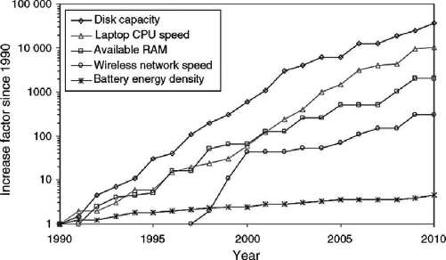
A commercial product available in the market [7] has a cable-less -component geophone that weighs lbs whereas its battery weights lbs. This means that weight has been cut-off by using the cable-free geophones, however, battery weight is added to the geophone weight. Hence, batteries also account for a substantial proportion of the overall weight and size of the seismic acquisition systems negating the benefit of going cable-free. This proportion is expected to increase more as the technology scales down. More importantly, batteries must always be recharged/replaced, and ultimately disposed of. This is a serious limitation to acquisition paradigms in which dozens or hundreds of battery-powered geophones are to be maintained. Replacement of batteries can be cumbersome and time-consuming, which may affect the seismic acquisition process. In addition, batteries can hinder the scalability of geophone networks. The main impediments in geophone advancements are the battery’s limited energy capacity and erratic lifetime efficiency. According to Moore’s Law, transistors double per one or two years [8]. However, the power density and life span of the batteries are limited and battery technology evolved very slowly (see Fig. 1). Wireless geophones make it necessary to have a provision for self-powered operation.
One of the most significant trends in electronic equipment technology since its inception has been the diminution in size and the boost in functionality. These days, small yet very powerful devices with wireless communication functionalities are commercially available. Over the past few decades, the size of the electronic circuit and the energy required for a single (binary) operation have been dramatically reduced. According to Moore’s law, integrated circuit technology evolves following a transistor size shrinking trend. Along with this trend, the supply voltage is also reduced due to reliability reasons. The ultimate result is a decrease in energy consumption owing to the size reduction of parasitic components. For a reduction of the scale with a factor (), the energy consumed by a particular shrunk circuit performing a specific task is decreased by [10]. Advances in low-power design, therefore, open up the possibility of using energy from the environment to power electronic circuits. Therefore, to meet the energy needs of the wireless geophone systems, new sources of long-lasting and regenerative power need to be developed. Energy harvesting is a very appealing choice for driving the geophones, as a node’s lifetime would be limited only by the failure of its own components.
Energy harvesting is a mechanism of deriving energy from natural sources. This usually involves extracting some residual energy which could be a by-product of an automated process or a natural phenomenon and, therefore considered as free energy [11]. Using the energy available in seismic fields would make it possible for wireless geophones to be fully self-sustaining, so that battery maintenance will eventually be eliminated.
In this context, this work presents approaches that could be used to harvest energy in seismic fields to power geophones. To the best of the authors’ knowledge, this is the first work that addresses energy harvesting techniques with regard to geophones. The electrical energy for operating a geophone can be obtained by tapping the energy from the electromagnetic field (using radio frequency (RF)), vibrations, sunlight, wind, and temperature gradients. These various sources of energies are abundantly available in seismic fields and can be advantageous. Hence, the harvested energy can be used to power up a geophone directly and/or charge a small battery (or a supercapacitor, see [12]) connected to it. Various energy sources and the duration of their availability is highlighted in Table 1. It can be noticed here that energies obtained using RF and temperature gradients (thermal) are available all day, so even if there is no seismic recording, these energies are still available and can be used to recharge the geophone batteries. Wind energy depends on the speed of the wind but in general, it is also available all the time. The huge vibroseis truck (used to produce seismic waveform) generates a tremendous amount of vibration energy that can be harvested. Vibration energy is available during the seismic shooting phases only. Therefore, the batteries may continue to charge all the time using available energy harvesting source(s), and the stored energy is then used for seismic recording and data transmission. Hence, the usual operation mode of an energy harvesting system in the seismic field implies harvesting during the peak time slots of energy availability, while the storage devices must meet the demand and supply in specified periods.
| Energy source | Availability |
|---|---|
| Solar | During day time |
| Vibration | During seismic shooting time |
| RF | hours a day |
| Thermal | hours a day |
| Wind | Depends on wind speed |
The benefits of energy harvesting with regards to the seismic acquisition networks are multifold and include: long-lasting operability, no chemical disposal (avoids the environmental contamination), cost saving, safety, maintenance-free, no charging points, inaccessible sites operability, flexibility, scalability, ease of installation, increase lifetime, and complete removal of supply wires.
In brief, this paper brings the following novel contributions:
-
•
The detailed energy requirement analysis by the wireless geophone is provided in Section 2. The analysis incorporates all the battery-dependent tasks, e.g., sensing/recording, processing, and wireless communication. The analysis provides a baseline idea about the minimum energy to be harvested to enable continuous sensing, processing, and communication tasks.
-
•
Various possible energy harvesting mechanisms, that can be utilized by wireless geophones, are provided in Sections 3-7. Particularly, the solar energy harvesting method with its implementation and feasibility details is discussed in Section 3. Vibration energy harvesting method with different types of such energy harvesters and their operation, design plus adequacy details are outlined in Section 4. Next, Section 5 is devoted to providing different means of energy harvesting through the wind. Various wind energy harvesters are discussed and their applicability for self-powered geophones is studied. A brief survey of the thermal energy harvesting method and its workability in seismic fields is elaborated in Section 6. Finally, Section 7 considers the RF energy harvesting method along with highlighting its usefulness and implementation requirements for wireless geophone applications.
-
•
A novel design of a multi-source wireless energy harvesting geophone is proposed in Section 8, which incorporates solar cell, antenna, piezoelectric, electromagnetic/electrostatic system, and thermoelectric generator to exploit all means of energy harvesting, i.e., solar, RF, wind, vibration, and thermal energy harvesting. It is important to mention here that the proposed design of a multi-source energy harvesting geophone can be easily modified to devise a multi-source energy harvesting based green wireless sensor networks, which can prolong the operating life of various IoT based sensor networks in the areas such as agriculture, smart cities, smart building, transportation systems, healthcare, and manufacturing.
2 Energy Requirement of a Geophone
Wireless geophones must be equipped with sensing (recording), processing, and communicating abilities. Therefore, geophones should have four key units: a sensing unit, a processing unit, a communication unit, and a power unit. The power consumed by sensing and processing units is used for data collection and data processing. Commercial geophones require an adequate amount of power to operate. For example, the geophone produced by a leading manufacturer [7] requires Wh battery for continuous recording for days ( hours per day). Here the power consumption is around mW for sensing and processing. For computing the power consumed by the communication unit, the following approach is adopted:
The transmitted signal from the wireless geophones experience certain path-loss. Since geophones are deployed in an open-field or rural environment, the path-loss (in dB) can be modeled as follows [13]:
| (1) |
where is the breakpoint distance, is the ground distance between the geophone and the base station (BS) either gateway or data center, is the BS antenna height, is the height of the geophone antenna above the ground, is the carrier frequency, and is the speed of light,
| (2) | |||||
| (3) |
and is the 3D distance between the geophone and the BS.
Considering the above path-loss and certain transmit power at the geophone, the received power at the BS is given by
| (4) |
m and m.
m and m.
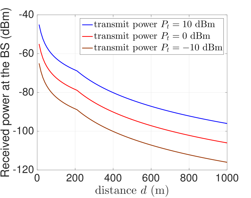
Considering typical values of carrier frequency GHz, BS antenna height m and geophone antenna height m, Fig. 3 depicts the BS received power as a function of distance for different values of the geophone transmit power . As expected, the received power decreases with the increase in the distance due to the increase in the path-loss. Considering typical noise power desnity of dBm/Hz, the noise power is given by
where is the transmission bandwidth (BW).
The above analysis can assist to calculate the signal-to-noise-ratio (SNR) at the BS for decoding the wireless geophone signal, which is given by
Remark 1
Fig. 3 shows that if we consider the transmit power, dBm ( mW) and the ground distance of km, the received power at the BS is dBm. This will lead to the received SNR of dB under the transmission BW of KHz (enough for achieving the data rate of kbps). This SNR is adequate to decode the signal with low bit-error rate. This implies that even assuming the quite far distance of km, we can achieve acceptable SNR of dB to decode the received signal at the BS.
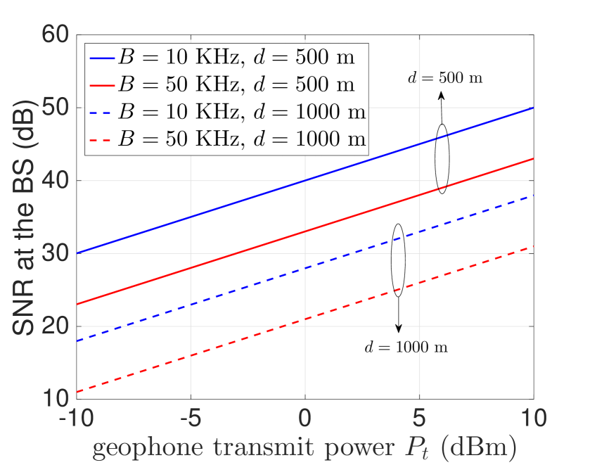
Fig. 3 plots the received SNR at the BS against different possible values of transmit power . This figure shows that at an extreme distance of km, the transmit power should be at least dBm to ensure SNR of dB under transmission BW of kHz. It is clear from Fig. 3 that the typical value of dBm, which is equal to mW, is enough to ensure adequate SNR with sufficient coverage.
Remark 2
Now it remains how to harvest sufficient energy from different means that can allow continuous sensing and processing (power consumption of around 159 mW), and communication (transmit power requirement of around mW from the geophone to cover up to km distance). The following sections elaborate on different means that can be employed to harvest energy at the geophone.
In the ensuing, various energy harvesting mechanisms are discussed and their feasibility in geophones are highlighted.
3 Solar Energy Harvesting
The presence of a significant amount of sunlight in outdoor environments makes it a vital energy source for geophones. A solar cell, or a photovoltaic cell, converts light energy into electricity by the photovoltaic effect. A solar cell is a tiny device made of semiconductor material. The first useful solar cell was developed in 1954 by the scientists at Bell Labs. Since then the field of harvesting solar energy has grown steadily. A number of solar power harvesting facilities are generating hundreds of megawatts of energy exist across the world [14].
Solar power is considered the most feasible form of renewable energy. This is because the Sun provides the highest energy density [15] as compared to other green energy sources such as wind, vibrations, etc. Outdoor solar panels can deliver energy densities in the range of 7.5 mW/cm2 [16]. Only a few wind energy harvesting methods have shown to outperform this number at very high wind speeds [17]. A number of different semiconductor materials/technologies have been used to develop solar cells. These are broadly divided into three generations as follows:
-
•
First generation: made of crystalline silicon cells
-
•
Second generation: made of thin-film cells
-
•
Third generation: made of organic, dye-sensitized, Perovskite, and multijunction cells.
The most popular of these solar/photovoltaic cells belonging to different generations and their efficiencies are listed in Table 2.
| Generation | Solar Cell Type | Efficiency | Power Density ()111These values are based on the power generated by a solar module under optimal operating conditions. | Ref. |
|---|---|---|---|---|
| First | Mono-crystalline | [18] | ||
| First | Poly-crystalline | [19] | ||
| Second | Amorphous Silicon | [20] | ||
| Second | Copper Indium di-Selenide | [21] | ||
| Second | Cadmium Telluride | [20] | ||
| Third | Nano-crystal/Quantum Dot | - | [22] | |
| Third | Polymer | - | [23] | |
| Third | Dye Sensitized | - | [24] | |
| Third | Concentrated | - | [25] | |
| Third | Perovskite | - | [26, 27] |
The solar cells based on the latest technology of concentrated and Perovskite material offer the highest efficiency as well as the highest energy density among all existing technologies according to lab experiments [26]. However, these technologies are still in their nascence and, therefore, have several stability limitations [28, 29]. These technologies hold a huge potential in generating high energy but are not commercially viable. Therefore, upon their commercialization in the future, these must be considered for the application of geophones.
3.1 Commercial Solar Cells
Commercial solar products use either the first generation or the second generation solar cells. The solar cells belonging to the third generation are still far from being commercialized due to stability issues highlighted in the previous section. Therefore, to harvest solar power for our application of geophones, the products that are available in the market are surveyed. A number of well-known solar manufacturers currently develop solar cells having maximum efficiencies in the range of 19% - 23%. Some of these are listed in Table 3 [30].
| Manufacturer | Min. Efficiency (%) | Max. Efficiency (%) | Avg. Efficiency (%) |
|---|---|---|---|
| SunPower | |||
| LG | |||
| REC Group | |||
| China Sunergy | |||
| Solaria | |||
| Panasonic | |||
| Silfab | |||
| Canadian Solar | |||
| CertainTeed Solar | |||
| Solartech Universal | |||
| JinkoSolar | |||
| JA Solar | |||
| Hanwha Q CELLS | |||
| Risen | |||
| Talesun Energy |
Any solar cell used with geophones should be resilient/robust against rugged environments. Most often the geophones are exposed to extreme conditions such as high temperatures, moisture, rain, sandstorms, snow, hail, wind, etc. which may result in corrosion, significant efficiency loss, and in some cases breakdown of solar cells. Therefore, for a commercially viable solar harvesting solution, different characteristics in addition to the solar cell efficiency need to be compared. Most notably, the following characteristics are important.
3.1.1 Power Tolerance
The power tolerance metric indicates the variation in the power output that could happen due to some unavoidable circumstances. These variations are measured as a percentage of the product’s power rating. Most manufacturers listed in Table 3 have a 0 W negative power tolerance which means that the actual power output will always be equal to or greater than the specified output. Any product that has a non-zero negative tolerance will result in reduced power output as compared to its rating and, therefore, may not be a good choice.
3.1.2 Temperature Coefficient
Solar panels rely solely on the light from the Sun which is also a source of heat. Interestingly, solar panels are also sensitive to high temperatures. The output of solar panels may reduce significantly at high temperatures. The temperature coefficient indicates the rate at which the efficiency of solar panels drops for every C above C. The temperature of C is used as a reference point as all solar panel characteristics are tested at this temperature. The temperature coefficients of the solar panels from some top manufacturers are listed in Table 4.
| Solar Manufacturer | Temperature Coefficient Range |
|---|---|
| China Sunergy | to |
| Hanwha Q CELLS | to |
| Hyundai | to |
| LG | to |
| SunPower | to |
| Panasonic | to |
3.1.3 Durability - Snow, Hail, and Wind Load Ratings
Our survey of several commercial products showed that when it comes to robustness against snow, hail, and wind, almost all solar panels are certified to withstand extreme conditions. We summarize the corresponding ratings in Table 5.
| Snow | Hail | Wind |
|---|---|---|
| Pa ( kg/m2) | mm at speed of kph | Pa (225 kph) |
International Electrotechnical Commission (IEC) has proposed two standards (IEC 61215 and IEC 61646) to evaluate the reliability of solar panels. Tests are designed following the guidelines of these standards to assess the wear and tear that solar panels will experience during their lifetime. Therefore, only those panels that are certified by IEC should be selected as they are guaranteed to withstand harsh environmental conditions.
While performing the survey, we found that the solar panels based on Maxeon technology (manufactured by SunPower) stood out among all other solar panels. This is mainly due to the structural difference between Maxeon and other conventional solar cells [32, 33]. Conventional cells use busbars that run through the face of the cell to capture electrical energy created by the cell. However, Maxeon cells are backed with solid copper to capture the electrical energy as shown in Fig. 4. This allows more surface area for the cell to capture energy which results in higher efficiency as evident from Table 3. Moreover, the use of copper at the back of the cell makes it resilient to corrosion and daily wear and tear from thermal expansion, etc.
In light of the detailed review and the discussion presented above, we conclude that the solar cells based on Maxeon technology are highly efficient and at the same time robust to the harmful effects of the environment. Therefore, we propose to equip geophones with solar cells based on Maxeon technology.

3.2 Photodiodes
A photodiode is also made of semiconductor material that converts light into an electric current. A photodiode is smaller than a solar cell. Its output is much lower as compared to a solar cell and is therefore mainly used as a sensor to detect light. Photodiodes have also been used to power up small electronics [35]. These include mainly wearable medical sensors. However, it is not used for larger electronic devices as the generated power is not sufficient for such devices. It is due to these reasons, we have not considered photodiodes as possible sunlight energy harvesting mechanisms.
3.3 Discussion
The solar energy harvesting infrastructure is low cost, and noise-free. The sunlight is available to every geophone and, therefore, solar energy can be harvested by any geophone, anywhere in the world. Despite these advantages, there are some limitations. For example, sunlight is not available at night. Similarly, different weather conditions may result in limited availability of energy. Furthermore, since geophones are placed on the ground, there is a risk that solar panels would be covered by dust, and hence lowering the efficiency. Therefore, a reliable green system must not rely solely on solar energy. This implies that any reliable green solution must be hybrid, i.e., it is designed to harness different forms of energies that are available throughout the year.
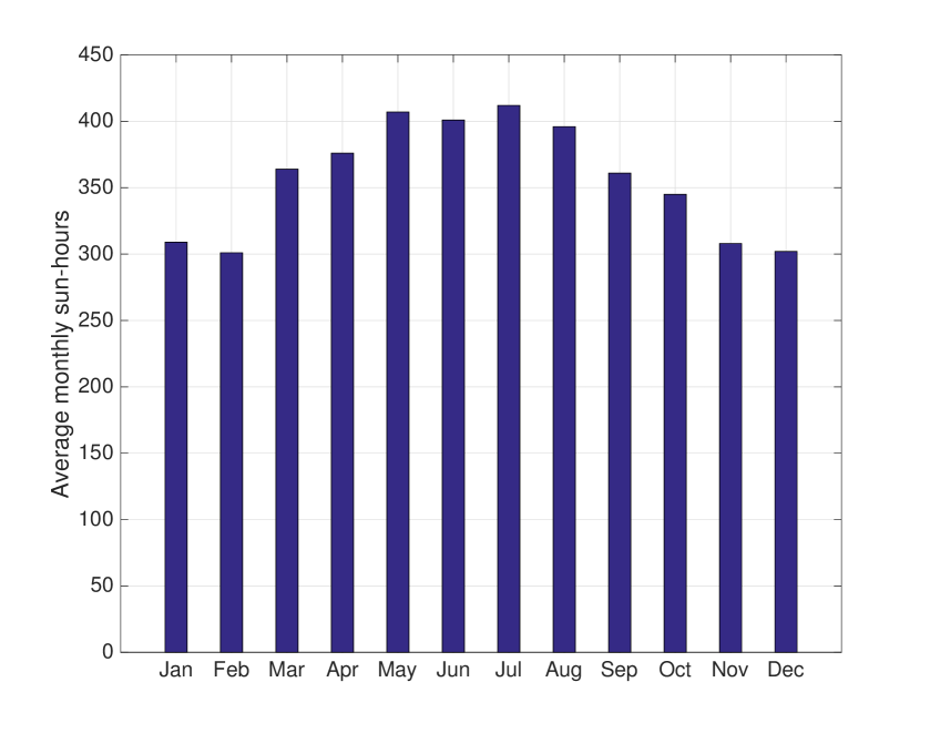
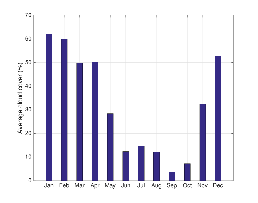
As a case study, we demonstrate the viability of energy harvesting by solar energy in one of the major city (Dammam) in the Eastern region of Saudi Arabia. Note that Saudi Arabia is chosen for the feasibility study of solar-powered wireless geophones as it is currently the largest oil producer and thus the largest consumer of geophones. The amount of harvested energy depends on the availability of the sunlight and the sky condition (whether it is clear or covered by the clouds). In this regard, Fig. 6 plots the average number of sun hours per month and Fig. 6 plots the average cloud coverage (in percentage) during different months in Dammam, Saudi Arabia [36]. It can be observed from Fig. 6 that sun is easily available around 12 hours per day. Fig. 6 shows that the cloud coverage is also in an acceptable range. Particularly, the cloud coverage is around or even less during summer (June-October), which shows that solar energy harvesting is very much suitable during summer days. However, the weather is hot for most part of the year and the temperature can reach up to ∘C in Summer, which reduces the output of solar panels.
It is, therefore, concluded that the presence of sunlight across the world and the availability of high energy density solar cells make it feasible to equip geophones with solar cells. These solar cells could be placed around the geophone body. The surface area of geophones exposed to sunlight might be small; however, the high energy density of the cells means a sizeable amount of energy could be harvested for the successful realization of wireless geophones. Furthermore, weather is often windy in the Eastern region of Saudi Arabia and the maximum speed is m/s ( km/h). It can be seen in Table 5 that solar panels can withstand these harsh environmental conditions.
4 Vibration Energy Harvesting
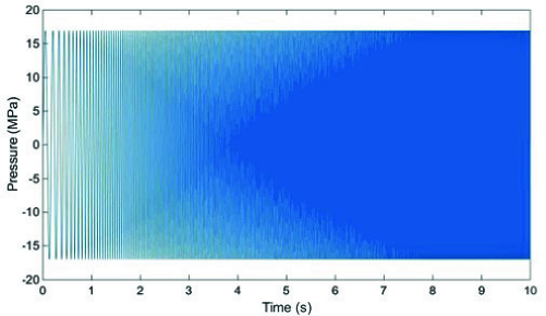
Vibration energy harvesting has been a subject of interest over the last decade. Vibration energy can be transformed into electric energy through various mechanisms, e.g., electromagnetic induction, electrostatic mechanism, or piezoelectric approach. Wireless geophones can harvest the tremendous amount of vibration energy that is generated by huge vibroseis trucks. These trucks generate vibration energy at regular intervals and thus provide a reliable source of energy to geophone. Vibroseis trucks inject a sweep (around to sec duration) of low frequencies into earth typically in the range of Hz and, therefore, it is critical to tune the energy harvesters resonant frequency accordingly. A slight deviation could drastically reduce the amount of energy being harvested [37]. An example of a linear sweep is shown in Fig. 7. Since the range of vibration frequency is known in our seismic scenario, the energy harvester can be designed with high efficiency.
Recently, new design approaches have been exploited based on the fact that a harvesting device’s power generation performance is confined to the resonance excitation. In numerous applications, ambient vibration is often broadband and random, and this type of excitation must be taken into account when designing energy harvesting devices. In order words, the operating frequency bandwidth of the harvester is usually confined to a specific range that cannot cover the random vibration frequencies of external sources. Recently, researchers have explored the concept of broadband energy harvesting, and many nonlinear power generators have been proposed in the literature [39, 40, 41, 42, 43, 44, 45, 46]. Table 6 shows a comparison of various mechanisms that are used to convert vibration energy to electrical energy. In the sequel, various vibration energy harvesting mechanisms are briefly discussed.
4.1 Piezoelectric-based Vibration Energy Harvester
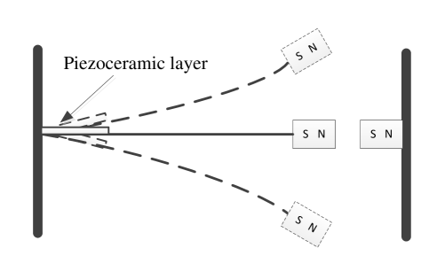
Piezoelectric generates an electric charge from mechanical strain. This phenomenon is known as the direct piezoelectric effect. In the case of vibration energy harvesting, ambient vibration around the energy harvesting unit/device induces the mechanical strain. Usually, the piezoelectric energy harvesters of the cantilever type are developed with a proof mass located at the free end of the beam. The electric energy can be generated from bending vibrations under excitation at the root of the beam. Among various energy harvesting structures, piezoelectric transducers are one of the widely known with nonlinear characteristics, and permanent magnets are often attached to the accompanying structures to reproduce the effect of external vibration forces. Piezoelectric energy harvester investigated in the literature using a magnetic oscillator [40, 47, 48, 49, 50, 51] is depicted in a schematic diagram (Fig. 8).
The authors in [52] discovered that harvester’s resonant frequency range is influenced by the geometric nonlinearity (in the presence or absence of the external magnets) and distance between the magnets. It has been demonstrated in [53] that the hybrid vibration energy harvesters (consisting of electromagnetic and piezoelectric generators) with nonlinear magnetic forces can effectively boost output performance under random excitation.
| Electrostatic | Electromagnetic | Piezoelectric | ||||||||||
|---|---|---|---|---|---|---|---|---|---|---|---|---|
| Material | Conductive capacitor | Neodymium iron boron | Lead zirconate titanate | |||||||||
| Advantages |
|
|
|
|||||||||
| Disadvantages |
|
|
|
Piezoelectric transducers are usually manufactured using aluminum nitride, lead zirconate titanate (PZT), quartz, and berlinite [54]. New lead-free piezoelectric transducers are developed to make it more environmentally friendly, e.g., piezoelectric nanogenerators that contain zinc nanowires (ZnO) [55, 56].
The piezoelectric materials are available in four types, namely thin films, single crystals, ceramics, and polymers. The piezoceramic materials, PZT-5A, PZT-5J, and PZT-5H are used for low power applications, while for high power applications PZT-8 and PZT-4 are used [57]. Porous PZT material has the benefits of stiffness control and good capacitance. Piezoelectric polymers provide high power density, as do piezoelectric ceramics. However, polymer-like polyvinylidene fluoride (PVDF) has poor adhesion to the material and a low electromechanical coupling coefficient. On the other hand, PZT is brittle and difficult to process, making it unsuitable for flexible application devices despite its high coupling coefficient [37, 58].
The piezoelectric generation has received a great deal of attention due to the simple structure of the piezoelectric transducer, its compact size, and power generation efficiency. The piezo patch size is very thin, and therefore the entire system is simpler and smaller than other energy harvesters [59]. Small-scale piezoelectric transducers are also more robust and most effective when compared to electromagnetic transducers, and hence are suitable for a compact structure such as airflow [60] and wind turbine energy harvester [61], sound wave energy harvester [62], and energy harvester based on the raindrop impact [63, 64, 65]. In order to improve the output obtained from piezoelectric, the authors in [65] utilized the voltage multiplier circuit in the energy harvester system. One of the issues, however, is achieving maximum power generation efficiency [66]. Several works [67, 68, 69] focused on frequency bandwidth extension to maximize the efficiency. The surveyed piezoelectric energy harvesters are listed in Table 7.
4.2 Electromagnetic-based Vibration Energy Harvesters
In an electromagnetic-based energy harvester, electrical energy is produced from the mechanical energy obtained by relative motion between a coil and conductive magnetized body. The design of an electromagnetic energy harvester consists of pick-up coil, magnet, mechanical barrier arm, and cantilever beam and is used for low-frequency range applications, i.e., Hz. Downsizing of the electromagnetic harvesters with optimum power output to be adequate for low power micro-system applications is the main challenge [89]. A major limitation of the micro-systems is the limited number of turns of the coil. Performance improvement is achieved by adjusting the external excitation frequency [90].
The effective harvesting bandwidth can be increased by using an excitation structure having multi-degrees of freedom system [91]. Another way of making bandwidth wider is to introduce nonlinearity in an energy harvesting system. The performance is enhanced when compared to the linear system. Coupling between tuning modes, hybrid transduction, and multi-modal arrays are several strategies used to improve efficiency through the incorporation of nonlinearity into the system [67, 92]. The authors in [93] propose a novel electromagnetic harvester designed to improve the operating frequency range using the dual resonator technique. The study alluded comprised of two separate resonator systems. Due to multi-vibration mode, multiple frequencies of various modes are tuned to a specific spectrum resulting in a wider bandwidth [94, 95].
Electromagnetic energy harvesters generate a good amount of power from weak vibration. Since power generated is proportional to the operating frequency, the frequency-up conversion can be used in order to obtain the desired amount of average power [96, 97]. In addition, magnetoelectric transducer together with a rotary pendulum has shown to have frequency-doubling characteristics, hence more power is produced from low frequency [98]. Conversely, the resonant frequency may be altered by introducing switching damping at the expense of some power loss [99]. Optimal performance is observed by Kluger et al. [100] for small value of electromagnetic damping in the case of linear systems and large damping value in the case of nonlinear systems. Electromagnetic energy harvesting systems typically occupy a comparatively larger space in the devices and suffer from magnetic deterioration and windage loss. Due to the size issue, the fabrication of magnetic coils on micro-and nano-scales is a challenging area. Hence, the authors in [101, 102, 103] proposed the design based on the fact that power increases substantially with the input amplitude, particularly with low-frequency vibrations. In a realistic scenario, an electromagnetic energy harvester is used to produce mW of power from bus vibration [104]. Electromagnetic energy harvesters perform better with larger size and periodic excitation, however, in the case of random vibration performance is weak [105, 106]. Various electromagnetic energy harvesters present in the literature are listed in Table 8.
4.3 Electrostatic-based Vibration Energy Harvesters
In electrostatic energy harvesters, charges are created by relative motion between two charged capacitor plates. This results in a potential difference in the capacitor and thus static electricity. Triboelectrification refers to the transfer of the charge between two surfaces in contact. Triboelectric nanogenerators based on electrostatic induction and triboelectrification effect are invented by Fan et al. [119] in order to harvest mechanical energy from the ambient environment.
Recently, Sequeira et al.[120] discovered the optimized capacitor plate pattern by utilizing the topological optimization method in order to enhance the average output power. In [121], the authors designed a single electrode mode nanogenerator for wearable products, in which silicon rubber and conductive thread are used as a negative dielectric material and an electrode, respectively. The electrical energy is produced by interaction of the silicon layer and human skin. However, the output energy is observed to be very low. Improved efficiency is shown in the freestanding triboelectric setup [122, 123]. In this setup, one dielectric material is free while another pair of dielectric material is fixed and attached to electrodes. Lateral sliding occurs between free and paired electrodes in this configuration. Research has been carried out in recent years to achieve optimum power output by hybridizing triboelectric materials with electromagnetic and piezoelectric materials [124, 125]. The authors in [126] have succeeded in generating energy that can supply power to LED bulbs and supercapacitors.
Electrostatic energy harvesters require an external voltage source. The key benefit is the production of extremely high voltage due to high internal impedance as compared to other energy harvesters [127]. Due to the absence of smart materials like optoelectronics, piezo patches, shape memory alloy, and magnetostrictive, triboelectric energy harvesters are long-lasting with adjustable coupling coefficient and low system cost. These harvesters are mostly used for small-scale purposes. Table 9 depicts various electrostatic energy harvesters present in the literature.
4.4 Discussion
For a geophone, a hybrid vibration energy harvester can be designed. The surface area and the internal space in geophone allow us to use piezoelectric, electromagnetic, and electrostatic energy harvesters altogether. A schematic diagram of a geophone is shown in Section 8 with various types of energy harvesters. However, it should be noted that geophones close to the vibroseis truck get the maximum vibration as compared to the ones that are far away. Hence, nearby geophones benefit more from the vibration energy harvesters for a particular shot. It is also worth mentioning that vibroseis truck moves within the seismic field and shots are carried out at various locations to cover all the area. Roughly, we can say that every geophone gets approximately the same amount of vibration energy per day.
Various commercial piezoelectric harvesters are available in the market to be suitable for the geophones [137]. Among them, PPA-2011, PPA-2014, and PPA-4011 are best suited for the application at hand (see Table 10 for PPA-4011 specifications). Furthermore, multiple piezo can be connected together for more power [138].
|
|
|
|
|
|
|
||||||||||||||
|---|---|---|---|---|---|---|---|---|---|---|---|---|---|---|---|---|---|---|---|---|
5 Wind Energy Harvesting
The presence of natural wind in outdoor environments makes it an important energy source for geophones. Wind energy has been used for centuries to perform different tasks. However, it is only recently that, with the advent of wireless sensor networks and the IoT, attention has been focused on miniature wind energy harvesting devices. In the past decade, the area of small-scale wind energy harvesting has gained attention and a number of designs have emerged.
Small-scale wind energy harvesters can help achieve the goal of self-powered sensors and/or tiny devices. Therefore, these harvesters are of huge interest to realize the idea of wireless geophones.
Wind energy can be harvested using two different mechanisms. These include:
-
•
the rotary movement of windmills/wind turbines, and
-
•
the aeroelastic behavior of materials
Most of the windmills and wind turbines work on the principle of electromagnetic induction to generate electricity. However, the rotary movement can be converted to electrical energy using other induction mechanisms as well. On the other hand, the harvesters utilizing the aeroelastic behavior of materials are mainly based on piezoelectric induction. In this section, we discuss some of the most important innovations/designs of miniature wind energy harvesters that could be successfully adopted to power geophones.
5.1 Windmills and Wind Turbines
Windmills and wind turbines are used to convert the kinetic energy of wind into mechanical energy. The mechanical energy can then be converted to electrical energy using any of the three induction mechanisms (piezoelectric, electromagnetic or electrostatic).
Table 11 lists the major developments in the area of harvesting wind energy using wind turbines. It can be observed that all of these designs are of large dimensions (several cms) and their power density is extremely low to be useful for geophones. The design proposed in [139] is an exception with a power density of 9.38 mW/cm2. However, the efficiency of this design reduces significantly at low wind speeds.
Actually, the efficiency of all harvesters based on rotary motion reduces drastically at lower wind speeds [140]. Designs shown in Table 11 have cut-in wind speeds in the range of 2 - 4.5 m/s with the exception of [141]. This indicates clearly that high wind speeds are needed to take advantage of the windmills and wind turbines. However, high wind speeds are not always available. Let us take an example of oil-rich Saudi Arabia where geophones find most of their usage. The average wind speed in Saudi Arabia, in general, is 6.73 m/s at a height of 100 m [142]. However, specifically, in the oil-rich region of Saudi Arabia (Dammam), the wind speeds vary from 0.2 - 5.5 m/s [143]. As geophones are placed on ground level, they will experience wind speeds that are much lower than the cut-in speeds.
Thus operating small-scale devices such as geophones and other sensors using such small-scale wind turbines is not a viable solution. However, other (non-rotary) designs for wind energy harvesting exist. Their merits and demerits are discussed from the point-of-view of geophones in the next sub-section.
| Dimension (cm) |
|
|
|
|
Induction Method | Ref. | ||||||||
|---|---|---|---|---|---|---|---|---|---|---|---|---|---|---|
| 4.2 | 9.38 | 130 | 11.8 | - | electromagnetic | [139] | ||||||||
| 2 | 1.368 | 4.3 | 10 | 4.5 | electromagnetic | [144] | ||||||||
| 4.5 | 3.9 | 62.5 | 15 | - | tribolelectric | [145]∗ | ||||||||
| 4 | 0.04377 | 0.55 | 20 | 4 | tribolelectric | [146] | ||||||||
| 4 | 0.0159 | 0.2 | 10 | - | electrostatic | [147] | ||||||||
|
0.0663 | 7.5 | 4.5 | 2.1 | piezoelectric | [148] | ||||||||
| cm3 | 0.0134 | 1.2 | 5.4 | 2.1 | piezoelectric | [149] | ||||||||
| cm3 | 0.0388 | 5 | 4.5 | 2.4 | piezoelectric | [150] | ||||||||
| cm3 | 0.00318 | 1.2 | 4.0 | 0.9 | piezoelectric | [141] | ||||||||
| cm3 | 0.0286 | 4 | 10 | 2 | piezoelectric | [61] |
∗ open-circuit measurements
5.2 Wind Energy Harvesters Utilizing Aeroelasticity
Wind energy can be harvested by taking advantage of the aeroelastic behavior of different materials. Aeroelasticity refers to the tendency of an elastic body to vibrate when it is exposed to a fluid flow (flow of wind/air in our case). These vibrations may be induced due to various aerodynamic phenomena such as flutter, vortex-induced vibrations, galloping, and buffeting. These phenomena are undesired in most of the applications such as in aircraft wings, bridges, transmission lines, etc. However, these phenomena can be used to generate power.
In this case, a wind energy harvester is exposed to a flow field which results in large limit-cycle oscillations. The kinetic energy of these oscillations may then be converted to electrical energy using either of the three transduction mechanisms. However, in almost all designs proposed in the literature, piezoelectric transduction is used due to the flexibility and efficiency that this method offers.
In the following, we list different types of harvesters that utilize various methods to take advantage of aeroelasticity. Each of these methods has been used in the literature to propose a number of harvester designs to efficiently harvest wind energy. These harvester types are:
-
•
Vortex-induced vibration (VIV) wind energy harvester
-
•
Galloping energy harvester
-
•
Wake Galloping energy harvester
-
•
Flutter-based energy harvester
-
•
Turbulence-induced vibration (TIV) wind energy harvester
The harvester designs that hold the potential to be most effective for our application of geophones are presented briefly in the following.
5.2.1 Vortex-induced Vibration (VIV) Wind Energy Harvester
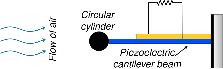
VIV is a phenomenon in which periodic vortices are shed by a bluff body when exposed to wind. These periodic vortices cause the body to oscillate [151, 152]. Therefore, VIV can be used to harvest wind energy by converting the oscillations into electrical energy. Piezoelectric transduction mechanism is usually used to convert oscillations into electrical energy. The design concept is shown in Fig. 9(a). Using piezoelectric material could allow VIV-based harvesters to be miniaturized without losing their capability to harvest energy at low wind speeds. Therefore, recently a microchip level energy harvester has been reported in the literature [153]. The VIV energy harvesters suitable for small-scale wind energy harvesting are listed in Table 12.
|
|
|
|
|
|
Ref. | ||||||||||||
|---|---|---|---|---|---|---|---|---|---|---|---|---|---|---|---|---|---|---|
| 2.91 cm, 3.6 cm | cm3 | 1.25 | 0.03 | 5 | 3.1 | [154] | ||||||||||||
| 2.5 cm, 11 cm | cm3 | 0.0918 | 5 | 5.5 | 2 | [155] | ||||||||||||
| 1.98 cm, 20.3 cm | cm3 | 1.47 | 0.1 | 1.192 | - | [156] | ||||||||||||
| 2 mm, 10 mm | mm3 | 5.66 | 1.6 | 4.48 | - | [153] |
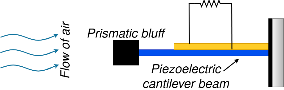
5.2.2 Galloping Vibrations Wind Energy Harvester
Galloping vibrations could be induced by replacing the smooth cylindrical bluff body in the schematic of Fig. 9(a) with a prismatic body as shown in Fig. 9(b). The prisms used to generate galloping vibrations could be of different shapes; for example, rectangular, triangular, D-shape, hexagonal, rectangular with a V-shape groove, etc. The galloping-induced vibrations have large amplitudes as compared to VIV and lend themselves for the stable acquisition of energy [157]. Galloping vibrations can be harvested using methods similar to those for VIV. Table 13 summarizes the performance of some prominent harvesters with different types and dimensions of the prismatic bluff bodies. It can be observed that galloping vibrations-based wind energy harvesters feature low cut-in speeds and are, therefore, useful in environments with slow wind.
|
|
|
|
|
|
|
Ref. | ||||||||||||||
|---|---|---|---|---|---|---|---|---|---|---|---|---|---|---|---|---|---|---|---|---|---|
|
cm, cm | 1.25 | [158] | ||||||||||||||||||
| Triangle |
|
- | [159] | ||||||||||||||||||
| Triangle | cm, cm | [160] | |||||||||||||||||||
| D-shape | cm, cm | [161] | |||||||||||||||||||
| Square | cm, cm |
|
[162] | ||||||||||||||||||
| Square | cm, cm | [163, 164] |
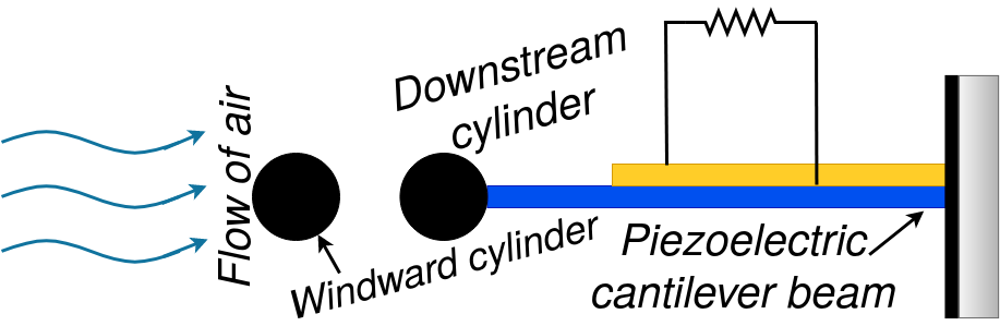
5.2.3 Wake Galloping Vibrations Wind Energy Harvester
Among various aerodynamic phenomena, wake galloping is the most suitable for a wind energy harvesting system. Such systems have low cut-in speeds and can operate on a wide range of wind speeds [165]. Wake galloping occurs when a fixed cylinder is placed in front of another cylinder with a flexible base. Due to the wakes from the windward cylinder, the flexible base cylinder vibrates significantly. The vibrations of the downstream cylinder are called wake galloping. These vibrations are significantly higher than those occurring due to the galloping phenomenon discussed earlier. Fig. 9(c) shows the schematic of a wake galloping-based wind energy harvesting system. Some prominent wake galloping-based harvesting designs are summarized in Table 14.
|
|
Spacing |
|
|
|
|
Ref. | ||||||||||||
|---|---|---|---|---|---|---|---|---|---|---|---|---|---|---|---|---|---|---|---|
|
|
cm | [165] | ||||||||||||||||
|
|
cm | [166] | ||||||||||||||||
|
|
cm | - | - | - | 4 | [167] |
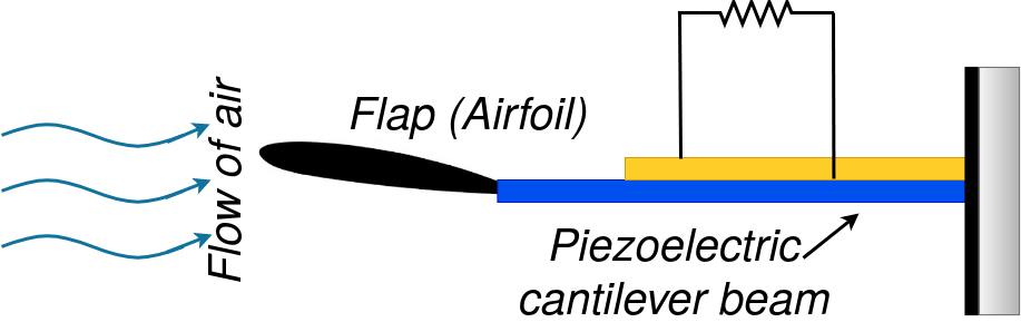
5.2.4 Flutter-induced Vibration Wind Energy Harvester
The schematic of Fig. 9(d) shows a typical system to harness wind energy using the aerodynamic phenomenon of flutter. In this system, a flap (airfoil) is connected at the end of a cantilever. The flow of air causes the flap to flutter and the resulting vibrations can be converted to electrical energy.
The cut-in wind speeds of flutter-based systems are usually high ( m/s). Therefore, these systems are suitable for high-wind regimes in general. However, some designs having normal cut-in wind speeds (2 - 4 m/s) exist and are summarized in Table 15.
|
|
Dimensions |
|
|
|
|
Ref. | ||||||||||||
|---|---|---|---|---|---|---|---|---|---|---|---|---|---|---|---|---|---|---|---|
| Airfoil |
|
|
[168] | ||||||||||||||||
| Flat plate |
|
|
[169] | ||||||||||||||||
| Flat plate |
|
|
[170] |
5.2.5 Turbulence-induced Vibration (TIV) Wind Energy Harvester
Turbulence-induced vibrations-based wind energy harvesters are one of the most practical small-scale solutions. Almost all of the above-mentioned designs work in laminar flow conditions. In other words, if the airflow is turbulent then these harvesters will become extremely inefficient and most often seize to harvest energy. Therefore, it is natural to design harvesters that can still work in turbulent winds. Another limitation of the harvesters mentioned earlier is that they generate vibrations (and generate electricity) only if the wind speed is above a minimum limit (cut-in speed). However, interestingly, turbulence-induced vibrations (TIVs) occur even if the wind speed is very low. This phenomenon can be used to design efficient turbulence-induced vibration wind energy harvesters [171, 172, 173, 174, 175, 176]. Some of the prominent efforts in this direction are summarized in Table 16.
| Dimensions |
|
|
|
|
Ref. | ||||||||
|---|---|---|---|---|---|---|---|---|---|---|---|---|---|
|
0.0184 | 4 | [171] | ||||||||||
|
[173] | ||||||||||||
| whole body: mm3 | 28.5 | 38.7 | [174] | ||||||||||
| PZT beam: mm3 | - | [175] | |||||||||||
|
- | [176] |
5.3 Discussion
It is important to note that, during this survey, we could not find any small/tiny-scale commercial solution for wind energy harvesting. However, the survey gives an interesting glimpse into the flurry of activity happening towards achieving tiny-scale wind energy harvesting solutions. These solutions are mainly targeted towards IoT sensors. We believe that the application of seismic energy harvesting provides a great incentive to the industry to seriously look into commercializing some of these wind energy harvesting ideas.
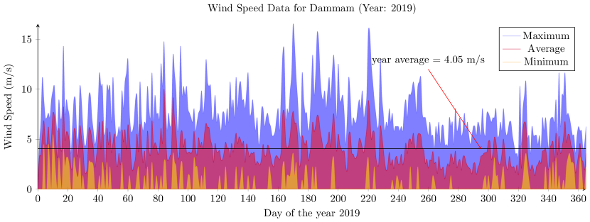
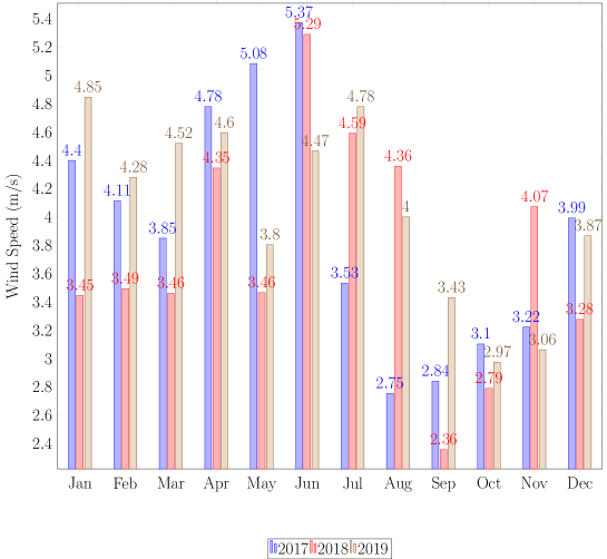
Further, the results of the survey show that most of the wind energy harvesting methods do not perform efficiently at low wind speeds. Thus such techniques are not suitable for regions with low average wind speeds. As an example, the wind speed data of Dammam city in Saudi Arabia is presented. Figure 10 shows the maximum, minimum, and average wind speeds in Dammam for each day of the year 2019. It could be easily noted that while maximum wind speeds are as high as 15 m/s, the average speed every day is around 4 m/s. Similarly, Fig. 11 provides a snapshot of the average wind speeds over the period of three years (2017-2019) again for Dammam city. With this data, it is obvious that for a wind energy harvesting system to be effective for Dammam city, the cut-in wind speed must be less than 4 m/s. All wind data has been acquired from the Weather Underground website [177].
Moreover, as the amount of energy generated by green energy harvesting solutions is not sufficient for the sustainable operation of a geophone, it is important to devise a hybrid system. Therefore, wind energy harvesting could be used along with other energy harvesting methods discussed in this paper to provide a sustainable solution.
6 Thermal Energy Harvesting
Another possible solution to power geophones is through energy harvesting from the temperature gradient that exists between the part of a geophone inserted inside the ground and the part that is exposed to the open environment in the seismic field. Thermal energy harvesting is coined as the reliable conversion of thermal energy to electricity with no moving parts. There are various strategies of thermal energy harvesting reported in the literature [178, 179, 180, 181, 182, 183, 184, 185]. However, the most notable are pyroelectric and thermoelectric generators. The first type, called pyroelectric generator, converts the temperature fluctuations in material to usable electrical energy. On the other hand, the thermoelectric generators, do not require temperature fluctuations; rather they rely on the temperature differences. In this mode of energy generation, the thermal gradient is converted into useful electrical energy utilizing the phenomenon termed as Seebeck effect which is summarized as follows.
When two dissimilar electrical conductors are joined together, a thermocouple is formed. An electromotive force is developed when the temperature difference is maintained between the two joining junctions. The induced voltage is proportional to the temperature gradient. The heat source provides an elevated temperature where the heat flows through a thermoelectric converter to a heat sink, which is maintained at a temperature well below that of the source. Hence, the flow of charge carriers between the hot and cold bodies creates voltage difference, leading to power generation.
The thermoelectric generators offer unique characteristics, such as; small footprint, lightweight, solid-state with no moving parts, free from noise, resistant to mechanical damage which means less maintenance, and long-term use in harsh environments. Table 17 shows applications where thermal energy is utilized for powering up different devices. It is apparent from Table 17 that a harvesting power in the range of hundreds of milliwatts is possible using thermal sources and could be potentially used for various applications.
| Applications | Heat utilized | Harvested Energy | Ref. | ||
|---|---|---|---|---|---|
| Seiko Thermic watch | Wrist and the environment at room temperature | µW | [178] | ||
| Nuclear Power Plant | Heat pipes | - | [179] | ||
| ThermaWatt | The heat of candle and room temperature | mW | [180] | ||
| DW-DF-10W Camp Stove | The heat of Propane stove | - | [181] | ||
| Radiator | Radiator ∘K & Air Voltage Current Power ∘K | mW | [182] | ||
| Pavement |
|
mW | [183] | ||
| Aircraft | Cargo skin and Cargo primary insulation | mW | [184] |
The thermoelectric generators are generally manufactured from either inorganic or polymer materials. The inorganic materials are mostly based on Bi-Te compounds. The thermoelectric generator consists of inorganic bulk materials embedded in a flexible polymer. The flexible thermoelectric generator can be attached to a curved surface as well. Table 18 shows the conversion efficiency for different thermoelectric generator materials. It is well known that the conversion efficiency of thermoelectric generators is very low, making them unsuitable for various standalone applications.
The performance of thermoelectric material is usually measured using a dimensionless figure of merit known as ZT value. The ZT value is directly proportional to the Seebeck coefficient and electrical conductivity. In order to improve the conversion efficiency of thermoelectric generators, a high value of ZT at room temperature is desired. The maximum conversion efficiency of is achieved when the ZT of the material is at oK as indicated in Table 18.
| Material | ZT (at ∘K) | T | Conversion efficiency () | Ref. |
|---|---|---|---|---|
| Bi2Te3 | [186] | |||
| Bi2Te3, Sb2Te3 | - | [187] | ||
| (BiSb)2Te3, Sb2Te3 | - | [188] | ||
| Bi2(Te,Se)3 | [189] | |||
| (Bi,Sb)2 Te3 | [189] | |||
| Bi2Te3 super-lattices | [189] |
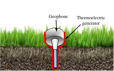
Thermoelectric generators generally require a temperature gradient of around ∘K to generate electrical power in the milliwatt range [186]. Here, we propose to use thermoelectric generators to be placed on the outer surface of the geophones installed in the seismic field. As shown in Fig. 12, a part of the geophone is under the ground. This creates a temperature gradient due to the temperature difference between the ground and the subsurface. Usually, a significant temperature difference exists between the upper surface of the seismic field and few centimeters below it. The harvested energy from the thermoelectric generator can be utilized to provide power to geophones installed in seismic fields. A closely related scenario has been recently studied by Sigrist et.al. [185]. The authors in the aforementioned work developed an end-to-end thermoelectric energy harvesting system to harvest energy from temperature gradients found at the natural ground-to-air boundary on the earth’s surface. Table 19 lists various thermoelectric generators that generate power using ground-to-air temperature gradient.
6.1 Discussion
In order to demonstrate the feasibility of thermal energy harvesters in seismic fields, we have recorded the temperature during the month of November in Dammam, Saudi Arabia (see Table 20) and found out the temperature difference of about ∘K exists cm below the surface. We strongly believe that this temperature difference will generate significant power to contribute to the energy required by geophones. This energy harvesting source is readily available for hours a day and can account for the significant portion of energy harvested from various sources. Moreover, the thermal energy harvesters are also robust to high temperatures and dust.
|
|
Power type | Ref. | ||||||
|---|---|---|---|---|---|---|---|---|---|
| Area of cm2 | Average | [190] | |||||||
|
Average | [191] | |||||||
|
Average | [192] | |||||||
| Area of cm2 | Average | [193] | |||||||
| Only Simulations setup |
|
- | [194] | ||||||
|
|
|
[195] |
| Time |
|
|
|
|
|||||||||||
|---|---|---|---|---|---|---|---|---|---|---|---|---|---|---|---|
| Morning | ∘K | ∘K | ∘K | ∘K | |||||||||||
| Noon | ∘K | ∘K | ∘K | ∘K | |||||||||||
| Evening | ∘K | ∘K | ∘K | ∘K | |||||||||||
| Night | ∘K | ∘K | ∘K | ∘K |
7 RF Energy Harvesting
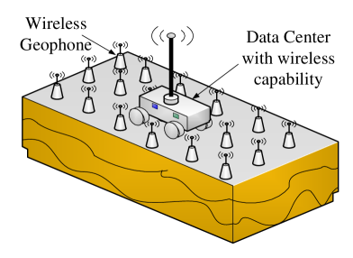
Harvesting energy from RF sources, also known as wireless energy harvesting, has found a lot of interest in recent years due to their wide applications as a substitute power source for various applications. Some interesting applications include battery-less power sources, RF tags, biomedical devices, and smart wireless sensor networks which require nanowatt to microwatt input power. We believe that wireless geophones can also take advantage of this technology. Specifically, the presence of an on-site data center provides an opportunity to power wireless geophones through RF energy. A typical layout of geophones in the field and an on-site data center is shown in Fig. 13. Power is readily available at the data centers and can be used to transmit energy to geophones using a wireless link.
7.1 RF Energy Sources
In general, a wireless geophone can harvest RF energy from various different sources. Any device emitting radio waves can be considered as a source for wireless energy harvesting. The frequency range of such sources depends on the type of transmitter. The most common radio sources are radio/TV broadcasting stations, satellites, wireless fidelity (Wi-Fi), global system for mobile communications (GSM), universal mobile telecommunications system (UMTS), and long term evolution (LTE) base stations. These sources cover a broad range of frequencies starting from kHz to all the way up to GHz of the electromagnetic spectrum. These RF energy sources are ubiquitous and are even available in the most inaccessible places.
A typical RF energy harvesting system consists of an antenna that receives the incident power, a matching network for maximizing the power transfer and minimizing the signal reflection, and an RF to DC rectifier [196]. RF energy harvesting can also be used along with data transfer in a communication system. Table 21 shows the power density of different RF sources. The power densities of these sources vary from nW/cm2 for GSM900 mobile terminal to nW/cm2 for GSM1800 base station.
| Band | Range (MHz) | Power Density (nW/cm2) |
|---|---|---|
| DTV | ||
| GSM900 (MT) | ||
| GSM900 (BT) | ||
| GSM1800 (MT) | ||
| GSM1800 (BT) | ||
| 3G(MT) | ||
| 3G(BT) | ||
| WiFi |
|
|
|
|
Load () |
|
Ref. | ||||||||||
|---|---|---|---|---|---|---|---|---|---|---|---|---|---|---|---|---|
|
[197] | |||||||||||||||
| Patch | [198] | |||||||||||||||
| Dipole | [199] | |||||||||||||||
| Patch | [200] | |||||||||||||||
|
[201] | |||||||||||||||
| Patch | [202] | |||||||||||||||
| Microstrip | [203] |
Table 22 shows the reported conversion efficiencies of different RF schemes with various antenna types. In [197] an RF energy harvester is reported where there is no antenna and a uniform transmission line was used for impedance matching. It is evident that dipole and microstrip antenna offered the best conversion efficiency followed by schemes based on patch antennas.
7.2 Optimal Signal Design for RF energy harvesting
The signal waveform design also plays an important role in efficient RF energy harvesting. Various waveform designs based on single or multiple antenna transmissions are reported in the literature [204, 205]. It has been shown that the design of an appropriate signal generation method that adapts as a function of the channel condition, significantly boosts the amount of harvested energy [205]. Particularly, the transmitted RF signal has been proposed to be the superposition of multiple sine-waves of unique amplitudes and phases, where the number of sine-waves depends upon the number of channel subbands.
Consider a general multiple-antenna transmitter with transmit antennas and assume channel subbands for a general frequency-selective channel. The transmit vector signal can be expressed as [205]
| (5) |
where is a vector of transmitted signal from antennas, with expresses the amplitude and phase of the subband signal on frequency and transmit antenna at time . If the frequency response of the multipath channel is given by , the optimal design of is given by [205]
| (6) |
where , and is a scaling factor whose optimal value is chosen to be [205], and is the transmit power budget. Under a single-antenna transmitter, the optimal design can be expressed as
| (7) |
7.3 Discussion
In the seismic exploration environment, we propose that wireless geophones tap the RF energy generated by the data center. In the seismic acquisition, geophones transmit the acquired data to the data center, which in turn sends acknowledgments [4] usually in the form of small frames. The fact that only small frames are sent in the downlink, makes it a perfect scenario to harvest energy from the RF signals. Since the downlink channel is idle most of the time, special signals (as discussed in Section 7.2) meant for energy harvesting can be sent over it. Moreover, geophones can be powered up using RF signals during both the shooting interval and the non-shooting periods. It means that RF signals can be used to power up geophones at any time.
In [4], the authors proposed a scheme for seismic data transmission utilizing wireless network based on IEEE802.11af standard. Usually the ambient energy from this RF source is not sufficient for powering the geophonesss and, therefore, other sources need to be added to the system. Nevertheless, we still believe that it can be utilized with other energy harvesting modes in a hybrid fashion. Furthermore, in the wireless sensor network literature, there is a growing trend of using unmanned aerial vehicles (UAV) to power up sensor nodes through RF signals [206, 207, 208]. The same concept can be applied to power up geophones located far away from the data center where RF energy harvesting is not feasible. In such large distance scenarios as geophone cannot transmit the recorded data to data centers directly, UAVs are sent to collect the data [209]. Thus the UAVs can be used to simultaneously receive data from and transmit power to the geophones.
As mentioned above that downlink contains only acknowledgments. The almost idle channel can be leveraged to intelligently design waveforms that are friendly for RF energy harvesting operation. Thus the amount of energy being harvested can be improved for the geophones. Another interesting design strategy could be to use these special waveforms that can maximize the RF energy harvesting efficiency as acknowledgments (positive or negative) for a geophone. Finally, the waveform design in (7) suggests multiple antennas at the data center and a single antenna at a geophone. This is perfect for a typical wireless seismic acquisition setup since it relieves a limited-power geophone while shifting heavy processing to the data center where power requirements are relaxed.
8 Proposed Design of Energy Harvesting Geophone
Figure 14 illustrates the proposed design of an energy harvesting geophone. It consists of solar cells on the top surface, piezoelectric and electromagnetic/electrostatic harvesters on the sides/edges and inside, respectively, coating of thermoelectric material on the whole body and antenna for RF energy harvesting.
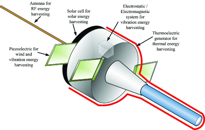
Based on this design, the average energy harvested per day can be approximated using the appropriate harvester designs highlighted in the above Sections 3-7. We have selected a suitable harvester per energy source based on the latest design, practicality, size, feasibility to geophones, maximum efficiency, and output power. From the Table 23, it can be concluded that the average harvested energy from multi-source can be used to meet the power requirements of a geophone. Furthermore, RF energy harvester is the least effective in this case, while solar energy harvesters contribute to most of the harvested energy. Although RF energy harvester adds very little to the overall harvested energy, we strongly believe that it can still be useful as geophones can be powered up by RF energy (transmitted from the data center) for hours a day especially during the evening/night when geophones are in sleep mode (no recording). In addition, recently, there are considerable improvements in the conversion efficiency of RF circuits (e.g. see [210, 211]) which could improve their performance in the future. The proposed design is a collective solution to harvest energy through various possible means. One can easily adapt to pick and choose some and drop others, depending upon the actual environmental situation. The hardware implementation and extensive comparison of various harvester designs in the real scenario is the focus of our future research.
| Energy source | Harvester design | Description |
|
|
|||||
|---|---|---|---|---|---|---|---|---|---|
| Solar | [20] |
|
4 hours | J | |||||
| Vibration | PPA-4011 |
|
|
J | |||||
| RF | WiFi Band |
|
24 hours | J | |||||
| Thermal | [195] | Available hours | 24 hours | J | |||||
| Wind | [170] | Available hours with average speed of m/s | 24 hours | J |
9 Conclusion
This paper has presented a comprehensive survey of the promising energy harvesting technologies for realizing self-powered geophones for seismic exploration. First, an overview of a typical wireless geophone with a focus on its energy requirements is provided. Next, detailed discussions about the state-of-the-art research contributions in various small-scale energy harvesting techniques suitable for geophones are presented. These included solar, vibration, wind, thermal, and RF energy harvesting methods. To this end, characteristics and design of different energy harvesting methods, their limitations, amount of harvested energy, comparisons, and various research challenges are discussed along with some real case studies. Finally, we have outlined the proposed design of a geophone equipped with the discussed energy harvesting mechanisms. It is concluded that energy harvesting and storage systems are to be planned based on the combination of more than one alternative energy source. It paves the way for a paradigm shift from traditional wired geophones to a truly autonomous and sustainable geophone energy harvesting network. The hardware design and implementation issues were identified as future research directions. We believe these insights will motivate further research towards the use of energy harvesting in geophones.
References
- [1] S. Savazzi and U. Spagnolini, “Wireless geophone networks for high-density land acquisition: Technologies and future potential,” Lead. Edge, vol. 27, pp. 882–886, July 2008.
- [2] N. Iqbal, A. Zerguine, and S. Khan, “OFDMA-TDMA-based seismic data transmission over TV white space,” IEEE Commun. Lett., vol. 25, pp. 1720–1724, May 2021.
- [3] S. Savazzi and U. Spagnolin, “Synchronous ultra-wide band wireless sensors networks for oil and gas exploration,” in 2009 IEEE Symp. Comput. Commun., pp. 907–912, July 2009.
- [4] N. Iqbal, S. Al-Dharrab, A. Muqaibel, W. Mesbah, and G. Stuber, “Analysis of wireless seismic data acquisition networks using Markov chain models,” in 2018 IEEE 29th Annu. Int. Symp. Pers. Indoor Mob. Radio Commun., pp. 1–5, 2018.
- [5] N. Iqbal, S. I. Al-Dharrab, A. H. Muqaibel, W. Mesbah, and G. L. Stuber, “Cross-layer design and analysis of wireless geophone networks utilizing TV white space,” IEEE Access, vol. 8, pp. 118542–118558, 2020.
- [6] V. A. Reddy, G. L. Stuber, S. Al-Dharrab, W. Mesbah, and A. H. Muqaibel, “Energy-efficient mm-wave backhauling via frame aggregation in wide area networks,” IEEE Trans. Wirel. Commun., pp. 1–17, 2021.
- [7] “Geospace technologies.” Available at: https://www.geospace.com/, [Accessed 20 Sept. 2020].
- [8] R. Schaller, “Moore’s law: past, present and future,” IEEE Spectrum, vol. 34, no. 6, pp. 52–59, 1997.
- [9] M. Niroomand and H. R. Foroughi, “A rotary electromagnetic microgenerator for energy harvesting from human motions,” J. Appl. Res. Technol., vol. 14, pp. 259–267, Aug. 2016.
- [10] J. L. GONZÁLEZ, A. Rubio, and F. Moll, “Human powered piezoelectric batteries to supply power to wearable electronic devices,” Int. J. Soc. Mater. Eng. Resour., vol. 10, no. 1, pp. 34–40, 2002.
- [11] M. Grossi, “Energy harvesting strategies for wireless sensor networks and mobile devices: A review,” Electronics, vol. 10, no. 6, p. 661, 2021.
- [12] S. Akbari, “Energy harvesting for wireless sensor networks review,” in 2014 Fed. Conf. Comput. Sci. Inf. Syst., pp. 987–992, IEEE, 2014.
- [13] “5G; Study on channel model for frequencies from 0.5 to 100 GHz (3GPP TR 38.901, version 14.3.0, Release 14),” ETSI Technical Report 138 901, 2018.
- [14] “Top 19 biggest solar farms in the world — solarfeeds marketplace.” Available at: https://solarfeeds.com/solar-farms-in-the-world/, [Accessed 20 Sept. 2020].
- [15] M. E. Mackay, Solar energy : An Introduction. Oxford University Press, 2015.
- [16] C. Ó. Mathúna, T. O’Donnell, R. V. Martinez-Catala, J. Rohan, and B. O’Flynn, “Energy scavenging for long-term deployable wireless sensor networks,” Talanta, vol. 75, pp. 613–623, May 2008.
- [17] “The future of energy: Why power density matters.” Available at: https://energycentral.com/c/ec/future-energy-why-power-density-matters, [Accessed 13 Nov. 2020].
- [18] S. Sharma, K. K. Jain, and A. Sharma, “Solar cells: In research and applications—a review,” Materials Sciences and Applications, vol. 06, no. 12, pp. 1145–1155, 2015.
- [19] P. Jayakumar, Solar Energy Resource Assessment Handbook. Renewable Energy Corporation Network for the Asia Pacific. 2009.
- [20] J. Luceño-Sánchez, A. Díez-Pascual, and R. Peña Capilla, “Materials for photovoltaics: State of art and recent developments,” Int. J. Mol. Sci., vol. 20, p. 976, Feb. 2019.
- [21] “Solar frontier achieves world record thin-film solar cell efficiency of 22.9.” Available at: http://www.solar-frontier.com/eng/news/2017/1220$\_$press.html, [Accessed 20 Sept. 2020].
- [22] D. Bozyigit, W. M. Lin, N. Yazdani, O. Yarema, and V. Wood, “A quantitative model for charge carrier transport, trapping and recombination in nanocrystal-based solar cells,” Nature Communications, vol. 6, p. 6180, 2015.
- [23] H. Yao, F. Bai, H. Hu, L. Arunagiri, J. Zhang, Y. Chen, H. Yu, S. Chen, T. Liu, J. Y. L. Lai, Y. Zou, H. Ade, and H. Yan, “Efficient all-polymer solar cells based on a new polymer acceptor achieving 10.3% power conversion efficiency,” ACS Energy Letters, vol. 4, pp. 417–422, feb 2019.
- [24] K. Sharma, V. Sharma, and S. S. Sharma, “Dye-sensitized solar cells: Fundamentals and current status,” vol. 13, p. 381, 2018.
- [25] G. S. Kinsey, W. Bagienski, A. Nayak, M. Liu, R. Gordon, and V. Garboushian, “Advancing efficiency and scale in CPV arrays,” IEEE Journal of Photovoltaics, vol. 3, no. 2, pp. 873–878, 2013.
- [26] “Best research-cell efficiencies.” Available at: https://www.nrel.gov/pv/assets/pdfs/best-research-cell-efficiencies.20190802.pdf, [Accessed 20 Sept. 2020].
- [27] Q. Zhao, A. Hazarika, X. Chen, S. P. Harvey, B. W. Larson, G. R. Teeter, J. Liu, T. Song, C. Xiao, L. Shaw, M. Zhang, G. Li, M. C. Beard, and J. M. Luther, “High efficiency perovskite quantum dot solar cells with charge separating heterostructure,” Nature Communications, vol. 10, p. 2842, Dec. 2019.
- [28] F. Matteocci, L. Cinà, E. Lamanna, S. Cacovich, G. Divitini, P. A. Midgley, C. Ducati, and A. Di Carlo, “Encapsulation for long-term stability enhancement of perovskite solar cells,” Nano Energy, vol. 30, pp. 162–172, Dec. 2016.
- [29] E. J. Juarez-Perez, L. K. Ono, M. Maeda, Y. Jiang, Z. Hawash, and Y. Qi, “Photodecomposition and thermal decomposition in methylammonium halide lead perovskites and inferred design principles to increase photovoltaic device stability,” Journal of Materials Chemistry A, vol. 6, no. 20, pp. 9604–9612, 2018.
- [30] “Solar panel efficiency: What panels are most efficient? — energysage.” Available at: https://news.energysage.com/what-are-the-most-efficient-solar-panels-on-the-market/, [Accessed 20 Sept. 2020].
- [31] “Does solar panel temperature coefficient matter? — solar.com.” Available at: https://www.solar.com/learn/does-solar-panel-temperature-coefficient-matter/, [Accessed 20 Sept. 2020].
- [32] “MAXEON GEN III SOLAR CELLS.” Available at: https://us.sunpower.com/sites/default/files/media-library/spec-sheets/sp-sunpower-maxeon-solar-cells-gen3.pdf, [Accessed 20 Sept. 2020].
- [33] “Why maxeon cells are far superior than conventional solar cells.” Available at: https://suncurves.com/en/v/19845/, [Accessed 20 Sept. 2020].
- [34] “Solar panels based on maxeon solar cell technology — sunpower.” Available at: https://us.sunpower.com/why-sunpower/maxeon-solar-cells, [Accessed 20 Sept. 2020].
- [35] A. Satharasinghe, T. Hughes-Riley, and T. Dias, “Photodiodes embedded within electronic textiles,” Scientific Reports, vol. 8, p. 16205, Dec. 2018.
- [36] “Sunrise and sunset times: Dammam, saudi arabia.” Available at: https://nyssf.com/sunpower-difference-maxeon-cells/, [Accessed 20 Sept. 2020].
- [37] C. Wei and X. Jing, “A comprehensive review on vibration energy harvesting: Modelling and realization,” Renew. Sustain. Energy Rev., vol. 74, pp. 1–18, July 2017.
- [38] Z. Huang, G. Li, and L. Hao, “Study on dynamics of vibrator baseplate at low and high frequencies,” J. Vibroengineering, vol. 19, pp. 2413–2426, June 2017.
- [39] D. A. W. Barton, S. G. Burrow, and L. R. Clare, “Energy harvesting from vibrations with a nonlinear oscillator,” J. Vib. Acoust., vol. 132, p. 021009, Apr. 2010.
- [40] M. Ferrari, V. Ferrari, M. Guizzetti, and D. Marioli, “A single-magnet nonlinear piezoelectric converter for enhanced energy harvesting from random vibrations,” Procedia Eng., vol. 5, pp. 1156–1159, 2010.
- [41] B. Mann and B. Owens, “Investigations of a nonlinear energy harvester with a bistable potential well,” J. Sound Vib., vol. 329, pp. 1215–1226, Apr. 2010.
- [42] C. Liu and X. Jing, “Vibration energy harvesting with a nonlinear structure,” Nonlinear Dyn., vol. 84, pp. 2079–2098, June 2016.
- [43] A. Triplett and D. D. Quinn, “The effect of non-linear piezoelectric coupling on vibration-based energy harvesting,” J. Intell. Mater. Syst. Struct., vol. 20, pp. 1959–1967, Nov. 2009.
- [44] L. Gammaitoni, I. Neri, and H. Vocca, “Nonlinear oscillators for vibration energy harvesting,” Appl. Phys. Lett., vol. 94, p. 164102, Apr. 2009.
- [45] F. Cottone, H. Vocca, and L. Gammaitoni, “Nonlinear energy harvesting,” Phys. Rev. Lett., vol. 102, p. 080601, Feb. 2009.
- [46] K. Vijayan, M. Friswell, H. Haddad Khodaparast, and S. Adhikari, “Non-linear energy harvesting from coupled impacting beams,” Int. J. Mech. Sci., vol. 96-97, pp. 101–109, June 2015.
- [47] M. Ferrari, V. Ferrari, M. Guizzetti, B. Andò, S. Baglio, and C. Trigona, “Improved energy harvesting from wideband vibrations by nonlinear piezoelectric converters,” Sensors Actuators A Phys., vol. 162, pp. 425–431, Aug. 2010.
- [48] A. S. De Paula, D. J. Inman, and M. A. Savi, “Energy harvesting in a nonlinear piezomagnetoelastic beam subjected to random excitation,” Mech. Syst. Signal Process., vol. 54-55, pp. 405–416, Mar. 2015.
- [49] L. Tang and Y. Yang, “A nonlinear piezoelectric energy harvester with magnetic oscillator,” Appl. Phys. Lett., vol. 101, p. 094102, Aug. 2012.
- [50] H. Vocca, I. Neri, F. Travasso, and L. Gammaitoni, “Kinetic energy harvesting with bistable oscillators,” Appl. Energy, vol. 97, pp. 771–776, Sept. 2012.
- [51] N. Cohen, I. Bucher, and M. Feldman, “Slow-fast response decomposition of a bi-stable energy harvester,” Mech. Syst. Signal Process., vol. 31, pp. 29–39, Aug. 2012.
- [52] P. Firoozy, S. E. Khadem, and S. M. Pourkiaee, “Broadband energy harvesting using nonlinear vibrations of a magnetopiezoelastic cantilever beam,” Int. J. Eng. Sci., vol. 111, pp. 113–133, Feb. 2017.
- [53] X. Zhou, S. Gao, H. Liu, and Y. Guan, “Effects of introducing nonlinear components for a random excited hybrid energy harvester,” Smart Mater. Struct., vol. 26, p. 015008, Jan. 2017.
- [54] C. R. Bowen, V. Y. Topolov, and H. A. Kim, Modern piezoelectric energy-harvesting materials, vol. 238 of Springer Series in Materials Science. Cham: Springer International Publishing, 2016.
- [55] Y. Qiu, H. Zhang, L. Hu, D. Yang, L. Wang, B. Wang, J. Ji, G. Liu, X. Liu, J. Lin, F. Li, and S. Han, “Flexible piezoelectric nanogenerators based on ZnO nanorods grown on common paper substrates,” Nanoscale, vol. 4, no. 20, p. 6568, 2012.
- [56] Q. Liao, Z. Zhang, X. Zhang, M. Mohr, Y. Zhang, and H.-J. Fecht, “Flexible piezoelectric nanogenerators based on a fiber/Zno nanowires/paper hybrid structure for energy harvesting,” Nano Res., vol. 7, pp. 917–928, June 2014.
- [57] X. Xu, D. Cao, H. Yang, and M. He, “Application of piezoelectric transducer in energy harvesting in pavement,” Int. J. Pavement Res. Technol., vol. 11, pp. 388–395, July 2018.
- [58] I. Jung, Y.-H. Shin, S. Kim, J.-y. Choi, and C.-Y. Kang, “Flexible piezoelectric polymer-based energy harvesting system for roadway applications,” Appl. Energy, vol. 197, pp. 222–229, July 2017.
- [59] C. M. A. Lopes and C. A. Gallo, “A review of piezoelectrical energy harvesting and applications,” in 2014 IEEE 23rd Int. Symp. Ind. Electron., pp. 1284–1288, IEEE, June 2014.
- [60] Y. Tsujiura, E. Suwa, T. Nishi, F. Kurokawa, H. Hida, and I. Kanno, “Airflow energy harvester of piezoelectric thin-film bimorph using self-excited vibration,” Sensors Actuators A Phys., vol. 261, pp. 295–301, July 2017.
- [61] M. A. Karami, J. R. Farmer, and D. J. Inman, “Parametrically excited nonlinear piezoelectric compact wind turbine,” Renew. Energy, vol. 50, pp. 977–987, Feb. 2013.
- [62] L. H. Fang, S. I. S. Hassan, R. A. Rahim, M. Isa, and B. bin Ismail, “Exploring piezoelectric for sound wave as energy harvester,” Energy Procedia, vol. 105, pp. 459–466, May 2017.
- [63] M. A. Ilyas and J. Swingler, “Piezoelectric energy harvesting from raindrop impacts,” Energy, vol. 90, pp. 796–806, Oct. 2015.
- [64] M. A. Ilyas and J. Swingler, “Towards a prototype module for piezoelectric energy harvesting from raindrop impacts,” Energy, vol. 125, pp. 716–725, Apr. 2017.
- [65] N. A. K. Z. Abidin, N. M. Nayan, M. M. Azizan, and A. Ali, “Analysis of voltage multiplier circuit simulation for rain energy harvesting using circular piezoelectric,” Mech. Syst. Signal Process., vol. 101, pp. 211–218, Feb. 2018.
- [66] Z. Yang, A. Erturk, and J. Zu, “On the efficiency of piezoelectric energy harvesters,” Extrem. Mech. Lett., vol. 15, pp. 26–37, 2017.
- [67] W. Yang and S. Towfighian, “A hybrid nonlinear vibration energy harvester,” Mech. Syst. Signal Process., vol. 90, pp. 317–333, June 2017.
- [68] L. Dhakar, H. Liu, F. Tay, and C. Lee, “A new energy harvester design for high power output at low frequencies,” Sensors Actuators A Phys., vol. 199, pp. 344–352, Sept. 2013.
- [69] K. A. Cook-Chennault, N. Thambi, and A. M. Sastry, “Powering MEMS portable devices—a review of non-regenerative and regenerative power supply systems with special emphasis on piezoelectric energy harvesting systems,” Smart Mater. Struct., vol. 17, p. 043001, Aug. 2008.
- [70] K. Morimoto, I. Kanno, K. Wasa, and H. Kotera, “High-efficiency piezoelectric energy harvesters of c-axis-oriented epitaxial PZT films transferred onto stainless steel cantilevers,” Sensors Actuators A Phys., vol. 163, pp. 428–432, Sept. 2010.
- [71] G. Chen, Q. Meng, H. Fu, and J. Bao, “Development and experiments of a micro piezoelectric vibration energy storage device,” Mech. Syst. Signal Process., vol. 40, pp. 377–384, Oct. 2013.
- [72] E. K. Reilly and P. K. Wright, “Modeling, fabrication and stress compensation of an epitaxial thin film piezoelectric microscale energy scavenging device,” J. Micromechanics Microengineering, vol. 19, p. 095014, Sept. 2009.
- [73] Y. Jeon, R. Sood, J.-h. Jeong, and S.-G. Kim, “MEMS power generator with transverse mode thin film PZT,” Sensors Actuators A Phys., vol. 122, pp. 16–22, July 2005.
- [74] B. S. Lee, S. C. Lin, W. J. Wu, X. Y. Wang, P. Z. Chang, and C. K. Lee, “Piezoelectric MEMS generators fabricated with an aerosol deposition PZT thin film,” J. Micromechanics Microengineering, vol. 19, p. 065014, June 2009.
- [75] P. Muralt, M. Marzencki, B. Belgacem, F. Calame, and S. Basrour, “Vibration energy harvesting with PZT micro device,” Procedia Chem., vol. 1, pp. 1191–1194, Sept. 2009.
- [76] R. Elfrink, T. M. Kamel, M. Goedbloed, S. Matova, D. Hohlfeld, Y. van Andel, and R. van Schaijk, “Vibration energy harvesting with aluminum nitride-based piezoelectric devices,” J. Micromechanics Microengineering, vol. 19, p. 094005, Sept. 2009.
- [77] W. Wang, T. Yang, X. Chen, X. Yao, and Qifa Zhou, “Vibration energy harvesting using piezoelectric circular diaphragm array,” in 2011 Int. Symp. Appl. Ferroelectr. 2011 Int. Symp. Piezoresponse Force Microsc. Nanoscale Phenom. Polar Mater., pp. 1–4, IEEE, July 2011.
- [78] D. Shen, J.-H. Park, J. Ajitsaria, S.-Y. Choe, H. C. Wikle, and D.-J. Kim, “The design, fabrication and evaluation of a MEMS PZT cantilever with an integrated si proof mass for vibration energy harvesting,” J. Micromechanics Microengineering, vol. 18, p. 055017, May 2008.
- [79] K. Tao, J. Miao, S. W. Lye, and X. Hu, “Sandwich-structured two-dimensional MEMS electret power generator for low-level ambient vibrational energy harvesting,” Sensors Actuators A Phys., vol. 228, pp. 95–103, June 2015.
- [80] D. Shen, J.-H. Park, J. H. Noh, S.-Y. Choe, S.-H. Kim, H. C. Wikle, and D.-J. Kim, “Micromachined PZT cantilever based on SOI structure for low frequency vibration energy harvesting,” Sensors Actuators A Phys., vol. 154, pp. 103–108, Aug. 2009.
- [81] E. Minazara, D. Vasic, F. Costa, and G. Poulin, “Piezoelectric diaphragm for vibration energy harvesting,” Ultrasonics, vol. 44, pp. e699–e703, Dec. 2006.
- [82] M. Rezaeisaray, M. E. Gowini, D. Sameoto, D. Raboud, and W. Moussa, “Low frequency piezoelectric energy harvesting at multi vibration mode shapes,” Sensors Actuators A Phys., vol. 228, pp. 104–111, June 2015.
- [83] H.-B. Fang, J.-Q. Liu, Z.-Y. Xu, L. Dong, L. Wang, D. Chen, B.-C. Cai, and Y. Liu, “Fabrication and performance of MEMS-based piezoelectric power generator for vibration energy harvesting,” Microelectronics J., vol. 37, pp. 1280–1284, Nov. 2006.
- [84] N. E. DuToit and B. L. Wardle, “Experimental verification of models for microfabricated piezoelectric vibration energy harvesters,” AIAA J., vol. 45, pp. 1126–1137, May 2007.
- [85] W. J. Choi, Y. Jeon, J.-H. Jeong, R. Sood, and S. G. Kim, “Energy harvesting MEMS device based on thin film piezoelectric cantilevers,” J. Electroceramics, vol. 17, pp. 543–548, Dec. 2006.
- [86] M. Ericka, D. Vasic, F. Costa, G. Poulin, and S. Tliba, “Energy harvesting from vibration using a piezoelectric membrane,” J. Phys. IV, vol. 128, pp. 187–193, Sept. 2005.
- [87] S. Roundy and P. K. Wright, “A piezoelectric vibration based generator for wireless electronics,” Smart Mater. Struct., vol. 13, pp. 1131–1142, Oct. 2004.
- [88] J.-Q. Liu, H.-B. Fang, Z.-Y. Xu, X.-H. Mao, X.-C. Shen, D. Chen, H. Liao, and B.-C. Cai, “A MEMS-based piezoelectric power generator array for vibration energy harvesting,” Microelectronics J., vol. 39, pp. 802–806, May 2008.
- [89] S. D. Moss, O. R. Payne, G. A. Hart, and C. Ung, “Scaling and power density metrics of electromagnetic vibration energy harvesting devices,” Smart Mater. Struct., vol. 24, p. 023001, Feb. 2015.
- [90] J. Seo, J.-S. Kim, U.-C. Jeong, Y.-D. Kim, Y.-C. Kim, H. Lee, and J.-E. Oh, “Optimization and performance improvement of an electromagnetic-type energy harvester with consideration of human walking vibration,” J. Korean Phys. Soc., vol. 68, pp. 431–442, Feb. 2016.
- [91] S.-J. Chen and J.-Y. Wu, “Fabrication of a 2-DOF electromagnetic energy harvester with in-phase vibrational bandwidth broadening,” Smart Mater. Struct., vol. 25, p. 095047, Sept. 2016.
- [92] N. Tran, M. H. Ghayesh, and M. Arjomandi, “Ambient vibration energy harvesters: A review on nonlinear techniques for performance enhancement,” Int. J. Eng. Sci., vol. 127, pp. 162–185, June 2018.
- [93] B. Ooi and J. Gilbert, “Design of wideband vibration-based electromagnetic generator by means of dual-resonator,” Sensors Actuators A Phys., vol. 213, pp. 9–18, July 2014.
- [94] K. Tao, S. Liu, S. W. Lye, J. Miao, and X. Hu, “A three-dimensional electret-based micro power generator for low-level ambient vibrational energy harvesting,” J. Micromechanics Microengineering, vol. 24, p. 065022, June 2014.
- [95] K. Tao, J. Wu, L. Tang, X. Xia, S. W. Lye, J. Miao, and X. Hu, “A novel two-degree-of-freedom MEMS electromagnetic vibration energy harvester,” J. Micromechanics Microengineering, vol. 26, p. 035020, Mar. 2016.
- [96] M. A. Halim, H. Cho, and J. Y. Park, “Design and experiment of a human-limb driven, frequency up-converted electromagnetic energy harvester,” Energy Convers. Manag., vol. 106, pp. 393–404, Dec. 2015.
- [97] M. A. Halim and J. Y. Park, “Modeling and experiment of a handy motion driven, frequency up-converting electromagnetic energy harvester using transverse impact by spherical ball,” Sensors Actuators A Phys., vol. 229, pp. 50–58, June 2015.
- [98] X. Dai, “An vibration energy harvester with broadband and frequency-doubling characteristics based on rotary pendulums,” Sensors Actuators A Phys., vol. 241, pp. 161–168, Apr. 2016.
- [99] B. Ooi, J. Gilbert, and A. R. A. Aziz, “Switching damping for a frequency-tunable electromagnetic energy harvester,” Sensors Actuators A Phys., vol. 234, pp. 311–320, Oct. 2015.
- [100] J. M. Kluger, T. P. Sapsis, and A. H. Slocum, “Robust energy harvesting from walking vibrations by means of nonlinear cantilever beams,” J. Sound Vib., vol. 341, pp. 174–194, Apr. 2015.
- [101] A. R. M. Siddique, S. Mahmud, and B. Van Heyst, “Energy conversion by ‘T-shaped’ cantilever type electromagnetic vibration based micro power generator from low frequency vibration sources,” Energy Convers. Manag., vol. 133, pp. 399–410, Feb. 2017.
- [102] A. Haroun, I. Yamada, and S. Warisawa, “Study of electromagnetic vibration energy harvesting with free/impact motion for low frequency operation,” J. Sound Vib., vol. 349, pp. 389–402, Aug. 2015.
- [103] A. Haroun, I. Yamada, and S. Warisawa, “Micro electromagnetic vibration energy harvester based on free/impact motion for low frequency–large amplitude operation,” Sensors Actuators A Phys., vol. 224, pp. 87–98, Apr. 2015.
- [104] N. Zhao, H. Luo, P. Liang, and M. Zhou, “The design and implementation of electromagnetic vibration energy acquisition system,” Energy Procedia, vol. 136, pp. 34–40, Oct. 2017.
- [105] W. Wang, J. Cao, N. Zhang, J. Lin, and W.-H. Liao, “Magnetic-spring based energy harvesting from human motions: Design, modeling and experiments,” Energy Convers. Manag., vol. 132, pp. 189–197, Jan. 2017.
- [106] M. A. Halim, H. Cho, M. Salauddin, and J. Y. Park, “A miniaturized electromagnetic vibration energy harvester using flux-guided magnet stacks for human-body-induced motion,” Sensors Actuators A Phys., vol. 249, pp. 23–31, Oct. 2016.
- [107] P. Glynne-Jones, M. Tudor, S. Beeby, and N. White, “An electromagnetic, vibration-powered generator for intelligent sensor systems,” Sensors Actuators A Phys., vol. 110, pp. 344–349, Feb. 2004.
- [108] X. Bai, Y. Wen, P. Li, J. Yang, X. Peng, and X. Yue, “Multi-modal vibration energy harvesting utilizing spiral cantilever with magnetic coupling,” Sensors Actuators A Phys., vol. 209, pp. 78–86, Mar. 2014.
- [109] R. Torah, P. Glynne-Jones, M. Tudor, T. O’Donnell, S. Roy, and S. Beeby, “Self-powered autonomous wireless sensor node using vibration energy sting,” Meas. Sci. Technol., vol. 19, p. 125202, Dec. 2008.
- [110] X. Wu and D.-W. Lee, “Magnetic coupling between folded cantilevers for high-efficiency broadband energy harvesting,” Sensors Actuators A Phys., vol. 234, pp. 17–22, Oct. 2015.
- [111] E. Arroyo, A. Badel, and F. Formosa, “Energy harvesting from ambient vibrations: Electromagnetic device and synchronous extraction circuit,” J. Intell. Mater. Syst. Struct., vol. 24, pp. 2023–2035, Nov. 2013.
- [112] S. H. Chae, S. Ju, Y. Choi, S. Jun, S. M. Park, S. Lee, H. W. Lee, and C.-H. Ji, “Electromagnetic vibration energy harvester using springless proof mass and ferrofluid as a lubricant,” J. Phys. Conf. Ser., vol. 476, p. 012013, Dec. 2013.
- [113] B. Yang, C. Lee, W. Xiang, J. Xie, J. Han He, R. K. Kotlanka, S. P. Low, and H. Feng, “Electromagnetic energy harvesting from vibrations of multiple frequencies,” J. Micromechanics Microengineering, vol. 19, p. 035001, Mar. 2009.
- [114] D.-A. Wang, C.-Y. Chiu, and H.-T. Pham, “Electromagnetic energy harvesting from vibrations induced by kármán vortex street,” Mechatronics, vol. 22, pp. 746–756, Sept. 2012.
- [115] D.-A. Wang and K.-H. Chang, “Electromagnetic energy harvesting from flow induced vibration,” Microelectronics J., vol. 41, pp. 356–364, June 2010.
- [116] E. Sardini and M. Serpelloni, “An efficient electromagnetic power harvesting device for low-frequency applications,” Sensors Actuators A Phys., vol. 172, pp. 475–482, Dec. 2011.
- [117] S. P. Beeby, R. N. Torah, M. J. Tudor, P. Glynne-Jones, T. O’Donnell, C. R. Saha, and S. Roy, “A micro electromagnetic generator for vibration energy harvesting,” J. Micromechanics Microengineering, vol. 17, pp. 1257–1265, July 2007.
- [118] E. Bouendeu, A. Greiner, P. J. Smith, and J. G. Korvink, “A low-cost electromagnetic generator for vibration energy harvesting,” IEEE Sens. J., vol. 11, pp. 107–113, Jan. 2011.
- [119] F.-R. Fan, Z.-Q. Tian, and Z. Lin Wang, “Flexible triboelectric generator,” Nano Energy, vol. 1, pp. 328–334, Mar. 2012.
- [120] D. Sequeira, K. Coonley, and B. Mann, “Topological optimization of variable area plate capacitors for coupled electromechanical energy harvesters,” J. Intell. Mater. Syst. Struct., vol. 30, pp. 2198–2211, Sept. 2019.
- [121] J. Park, A. Y. Choi, C. J. Lee, D. Kim, and Y. T. Kim, “Highly stretchable fiber-based single-electrode triboelectric nanogenerator for wearable devices,” RSC Adv., vol. 7, no. 86, pp. 54829–54834, 2017.
- [122] Y. Su, G. Xie, T. Xie, H. Zhang, Z. Ye, Q. Jing, H. Tai, X. Du, and Y. Jiang, “Wind energy harvesting and self-powered flow rate sensor enabled by contact electrification,” J. Phys. D. Appl. Phys., vol. 49, p. 215601, June 2016.
- [123] G. Zhu, C. Pan, W. Guo, C.-Y. Chen, Y. Zhou, R. Yu, and Z. L. Wang, “Triboelectric-generator-driven pulse electrodeposition for micropatterning,” Nano Lett., vol. 12, pp. 4960–4965, Sept. 2012.
- [124] H. Askari, E. Asadi, Z. Saadatnia, A. Khajepour, M. B. Khamesee, and J. Zu, “A hybridized electromagnetic-triboelectric self-powered sensor for traffic monitoring: concept, modelling, and optimization,” Nano Energy, vol. 32, pp. 105–116, Feb. 2017.
- [125] J. He, T. Wen, S. Qian, Z. Zhang, Z. Tian, J. Zhu, J. Mu, X. Hou, W. Geng, J. Cho, J. Han, X. Chou, and C. Xue, “Triboelectric-piezoelectric-electromagnetic hybrid nanogenerator for high-efficient vibration energy harvesting and self-powered wireless monitoring system,” Nano Energy, vol. 43, pp. 326–339, Jan. 2018.
- [126] H. Shao, Z. Wen, P. Cheng, N. Sun, Q. Shen, C. Zhou, M. Peng, Y. Yang, X. Xie, and X. Sun, “Multifunctional power unit by hybridizing contact-separate triboelectric nanogenerator, electromagnetic generator and solar cell for harvesting blue energy,” Nano Energy, vol. 39, pp. 608–615, Sept. 2017.
- [127] R. T. Aljadiri, L. Y. Taha, and P. Ivey, “Electrostatic energy harvesting systems: A better understanding of their sustainabilityelectrostatic energy harvesting systems: A better understanding of their sustainability,” J. Clean Energy Technol., vol. 5, pp. 409–416, Sept. 2017.
- [128] T. Tsutsumino, Y. Suzuki, N. Kasagi, and Y. Sakane, “Seismic power generator using high-performance polymer electret,” in 19th IEEE Int. Conf. Micro Electro Mech. Syst., pp. 98–101, IEEE, 2006.
- [129] M. Miyazaki, H. Tanaka, G. Ono, T. Nagano, N. Ohkubo, T. Kawahara, and K. Yano, “Electric-energy generation using variable-capacitive resonator for power-free LSI: efficiency analysis and fundamental experiment,” in Proc. 2003 Int. Symp. Low Power Electron. Des. 2003. ISLPED ’03., pp. 193–198, ACM, 2003.
- [130] S. Roundy, P. K. Wright, and K. S. J. Pister, “Micro-electrostatic vibration-to-electricity converters,” in Microelectromechanical Syst., pp. 487–496, ASMEDC, Jan. 2002.
- [131] Y. Naruse, N. Matsubara, K. Mabuchi, M. Izumi, and S. Suzuki, “Electrostatic micro power generation from low-frequency vibration such as human motion,” J. Micromechanics Microengineering, vol. 19, p. 094002, Sept. 2009.
- [132] E. Torres and G. Rincon-Mora, “Electrostatic energy-harvesting and battery-charging CMOS system prototype,” IEEE Trans. Circuits Syst. I Regul. Pap., vol. 56, pp. 1938–1948, Sept. 2009.
- [133] F. Wang and O. Hansen, “Electrostatic energy harvesting device with out-of-the-plane gap closing scheme,” Sensors Actuators A Phys., vol. 211, pp. 131–137, May 2014.
- [134] R. Tashiro, N. Kabei, K. Katayama, Y. Ishizuka, F. Tsubol, and K. Tsuchiya, “Development of an electrostatic generator that harnesses the motion of a living body. use of a resonant phenomenon.,” JSME Int. J. Ser. C, vol. 43, no. 4, pp. 916–922, 2000.
- [135] R. Tashiro, N. Kabei, K. Katayama, E. Tsuboi, and K. Tsuchiya, “Development of an electrostatic generator for a cardiac pacemaker that harnesses the ventricular wall motion,” J. Artif. Organs, vol. 5, pp. 239–245, Dec. 2002.
- [136] Y. Suzuki, D. Miki, M. Edamoto, and M. Honzumi, “A MEMS electret generator with electrostatic levitation for vibration-driven energy-harvesting applications,” J. Micromechanics Microengineering, vol. 20, p. 104002, Oct. 2010.
- [137] “Your piezo experts.” Available at: https://piezo.com, [Accessed 20 Sept. 2020].
- [138] “Piezo systems manuals.” Available at: https://support.piezo.com/article/63-previous-manuals-datasheets, [Accessed 20 Sept. 2020].
- [139] D. Rancourt, A. Tabesh, and L. G. Fréchette, “Evaluation of centimeter-scale micro windmills: aerodynamics and electromagnetic power generation,” in Power MEMS, vol. 9, pp. 93–96, 2007.
- [140] S. Ragunath V, J. K. Pandey, A. K. Mondal, and A. Karn, “Wind turbines for electricity generation operating in the low wind velocity regime,” SSRN Electronic Journal, May 2019.
- [141] S. Bressers, D. Avirovik, M. Lallart, D. J. Inman, and S. Priya, “Contact-less wind turbine utilizing piezoelectric bimorphs with magnetic actuation,” in Proceedings of the 28th IMAC, A Conference on Structural Dynamics, pp. 233–243, 2010.
- [142] “Average annual wind speed at 100 m/s in 2016 — general authority for statistics.” Available at: https://www.stats.gov.sa/en/indicators/225, [Accessed 20 Sept. 2020].
- [143] “earth :: a global map of wind, weather, and ocean conditions.” Available at: https://earth.nullschool.net/\#current/wind/surface/level/, [Accessed 20 Sept. 2020].
- [144] A. Bansal, D. A. Howey, and A. S. Holmes, “CM-scale air turbine and generator for energy harvesting from low-speed flows,” in TRANSDUCERS 2009 - 2009 International Solid-State Sensors, Actuators and Microsystems Conference, pp. 529–532, 2009.
- [145] Y. Xie, S. Wang, L. Lin, Q. Jing, Z. H. Lin, S. Niu, Z. Wu, and Z. L. Wang, “Rotary triboelectric nanogenerator based on a hybridized mechanism for harvesting wind energy,” ACS Nano, vol. 7, no. 8, pp. 7119–7125, 2013.
- [146] M. Perez, S. Boisseau, M. Geisler, G. Despesse, and J. L. Reboud, “A triboelectric wind turbine for small-scale energy harvesting,” Journal of Physics: Conference Series, vol. 773, no. 1, p. 012118, 2016.
- [147] M. Perez, S. Boisseau, and J. L. Reboud, “Design and performance of a small-scale wind turbine exploiting an electret-based electrostatic conversion,” Journal of Physics: Conference Series, vol. 646, no. 1, p. 012009, 2015.
- [148] S. Priya, “Modeling of electric energy harvesting using piezoelectric windmill,” Applied Physics Letters, vol. 87, no. 18, p. 184101, 2005.
- [149] Z. Chen and R. Stewart, “A multi-window algorithm for real-time automatic detection and picking of p-phases of seismic events,” CREWES Res. Rep., vol. 18, pp. 15.1–15.9, 2006.
- [150] R. Myers, M. Vickers, H. Kim, and S. Priya, “Small scale windmill,” Applied Physics Letters, vol. 90, no. 5, p. 054106, 2007.
- [151] T. Sarpkaya, “A critical review of the intrinsic nature of vortex-induced vibrations,” Journal of Fluids and Structures, vol. 19, pp. 389–447, May 2004.
- [152] C. Williamson and R. Govardhan, “Vortex-induced vibrations,” Annual Review of Fluid Mechanics, vol. 36, pp. 413–455, Jan. 2004.
- [153] Y. J. Lee, Y. Qi, G. Zhou, and K. B. Lua, “Vortex-induced vibration wind energy harvesting by piezoelectric MEMS device in formation,” Scientific Reports, vol. 9, no. 1, pp. 1–11, 2019.
- [154] X. Gao, W. H. Shih, and W. Y. Shih, “Flow energy harvesting using piezoelectric cantilevers with cylindrical extension,” IEEE Transactions on Industrial Electronics, vol. 60, no. 3, pp. 1116–1118, 2013.
- [155] L. A. Weinstein, M. R. Cacan, P. M. So, and P. K. Wright, “Vortex shedding induced energy harvesting from piezoelectric materials in heating, ventilation and air conditioning flows,” Smart Materials and Structures, vol. 21, p. 045003, Apr. 2012.
- [156] H. D. Akaydin, N. Elvin, and Y. Andreopoulos, “The performance of a self-excited fluidic energy harvester,” Smart Materials and Structures, vol. 21, p. 025007, Feb. 2012.
- [157] D. Li, Y. Wu, A. Da Ronch, and J. Xiang, “Energy harvesting by means of flow-induced vibrations on aerospace vehicles,” vol. 86, pp. 28–62, Oct. 2016.
- [158] K. Zhao, Q. Zhang, and W. Wang, “Optimization of galloping piezoelectric energy harvester with V-shaped groove in low wind speed,” Energies, vol. 12, p. 4619, Dec. 2019.
- [159] T. Tan, X. Hu, Z. Yan, and W. Zhang, “Enhanced low-velocity wind energy harvesting from transverse galloping with super capacitor,” Energy, vol. 187, p. 115915, Nov. 2019.
- [160] J. Sirohi and R. Mahadik, “Piezoelectric wind energy harvester for low-power sensors,” Journal of Intelligent Material Systems and Structures, vol. 22, pp. 2215–2228, Dec. 2011.
- [161] J. Sirohi and R. Mahadik, “Harvesting wind energy using a galloping piezoelectric beam,” Journal of Vibration and Acoustics, Transactions of the ASME, vol. 134, no. 1, 2012.
- [162] J. Zhao and Z. You, “A shoe-embedded piezoelectric energy harvester for wearable sensors,” Sensors, vol. 14, pp. 12497–12510, July 2014.
- [163] L. Zhao, J. Liang, L. Tang, Y. Yang, and H. Liu, “Enhancement of galloping-based wind energy harvesting by synchronized switching interface circuits,” in 2015 SPIE Smart Struct. Mater. + Nondestruct. Eval. Heal. Monit., vol. 187, p. 94310E, Apr. 2015.
- [164] L. Zhao, L. Tang, J. Liang, and Y. Yang, “Synergy of wind energy harvesting and synchronized switch harvesting interface circuit,” IEEE/ASME Transactions on Mechatronics, vol. 22, pp. 1093–1103, Apr. 2017.
- [165] H. J. Jung and S. W. Lee, “The experimental validation of a new energy harvesting system based on the wake galloping phenomenon,” Smart Materials and Structures, vol. 20, p. 055022, May 2011.
- [166] A. Abdelkefi, J. M. Scanlon, E. McDowell, and M. R. Hajj, “Performance enhancement of piezoelectric energy harvesters from wake galloping,” Applied Physics Letters, vol. 103, p. 033903, July 2013.
- [167] M. Usman, A. Hanif, I. H. Kim, and H. J. Jung, “Experimental validation of a novel piezoelectric energy harvesting system employing wake galloping phenomenon for a broad wind spectrum,” Energy, vol. 153, pp. 882–889, June 2018.
- [168] M. Bryant and E. Garcia, “Modeling and testing of a novel aeroelastic flutter energy harvester,” Journal of Vibration and Acoustics, Transactions of the ASME, vol. 133, no. 1, p. 011010, 2011.
- [169] S. D. Kwon, “A T-shaped piezoelectric cantilever for fluid energy harvesting,” Applied Physics Letters, vol. 97, p. 164102, Oct. 2010.
- [170] J. Park, G. Morgenthal, K. Kim, S.-D. Kwon, and K. H. Law, “Power evaluation of flutter-based electromagnetic energy harvesters using computational fluid dynamics simulations,” Journal of Intelligent Material Systems and Structures, vol. 25, pp. 1800–1812, Sept. 2014.
- [171] J. D. Hobeck and D. J. Inman, “Artificial piezoelectric grass for energy harvesting from turbulence-induced vibration,” Smart Materials and Structures, vol. 21, p. 105024, Oct. 2012.
- [172] J. D. Hobeck and D. J. Inman, “A distributed parameter electromechanical and statistical model for energy harvesting from turbulence-induced vibration,” Smart Materials and Structures, vol. 23, p. 115003, Nov. 2014.
- [173] H. D. Akaydin, N. Elvin, and Y. Andreopoulos, “Energy harvesting from highly unsteady fluid flows using piezoelectric materials,” Journal of Intelligent Material Systems and Structures, vol. 21, pp. 1263–1278, Sept. 2010.
- [174] H. Liu, S. Zhang, T. Kobayashi, T. Chen, and C. Lee, “Flow sensing and energy harvesting characteristics of a wind-driven piezoelectric pb(zr0.52, ti0.48)o3 microcantilever,” Micro and Nano Letters, vol. 9, no. 4, pp. 286–289, 2014.
- [175] H. Liu, S. Zhang, R. Kathiresan, T. Kobayashi, and C. Lee, “Development of piezoelectric microcantilever flow sensor with wind-driven energy harvesting capability,” Applied Physics Letters, vol. 100, p. 223905, May 2012.
- [176] X. He, Z. Shang, Y. Cheng, and Y. Zhu, “A micromachined low-frequency piezoelectric harvester for vibration and wind energy scavenging,” Journal of Micromechanics and Microengineering, vol. 23, p. 125009, Dec. 2013.
- [177] “Local weather forecast, news and conditions — weather underground.” Available at: https://www.wunderground.com/, [Accessed 20 Sept. 2020].
- [178] Xin Lu and Shuang-Hua Yang, “Thermal energy harvesting for WSNs,” in 2010 IEEE Int. Conf. Syst. Man Cybern., pp. 3045–3052, IEEE, Oct. 2010.
- [179] J. Chen, J. Klein, Y. Wu, S. Xing, R. Flammang, M. Heibel, and L. Zuo, “A thermoelectric energy harvesting system for powering wireless sensors in nuclear power plants,” IEEE Trans. Nucl. Sci., vol. 63, pp. 2738–2746, Oct. 2016.
- [180] “Thermawatt, a candle powered TEG.” Available at: http://www.tegmart.com/diy-teg-kits/diy-candlepowered-teg-with-led-options/, [Accessed 20 Sept. 2020].
- [181] “DW-DF-10W Camp Stove TEG.” Available at: http://www.tegpower.com/pro2.htm, [Accessed 20 Sept. 2020].
- [182] B. Franciscatto, “Design and implementation of a new low-power consumption dsrc transponder,” Ph.D. Diss. Univ. Grenoble Alpes, 2014.
- [183] G. Wu and X. Yu, “Thermal energy harvesting across pavement structure,” in 2012 Transp. Res. board 91st Annu. Meet., pp. 311–316, 2012.
- [184] M. R. Pearson, M. J. Eaton, R. Pullin, C. A. Featherston, and K. M. Holford, “Energy harvesting for aerospace structural health monitoring systems,” J. Phys. Conf. Ser., vol. 382, p. 012025, Aug. 2012.
- [185] L. Sigrist, N. Stricker, D. Bernath, J. Beutel, and L. Thiele, “Thermoelectric energy harvesting from gradients in the earth surface,” IEEE Trans. Ind. Electron., vol. 67, pp. 9460–9470, Nov. 2020.
- [186] W.-H. Chen, S.-R. Huang, and Y.-L. Lin, “Performance analysis and optimum operation of a thermoelectric generator by taguchi method,” Appl. Energy, vol. 158, pp. 44–54, Nov. 2015.
- [187] B. Jang, S. Han, and J.-Y. Kim, “Optimal design for micro-thermoelectric generators using finite element analysis,” Microelectron. Eng., vol. 88, pp. 775–778, May 2011.
- [188] M. Barma, M. Riaz, R. Saidur, and B. Long, “Estimation of thermoelectric power generation by recovering waste heat from biomass fired thermal oil heater,” Energy Convers. Manag., vol. 98, pp. 303–313, July 2015.
- [189] W.-H. Chen, P.-H. Wu, X.-D. Wang, and Y.-L. Lin, “Power output and efficiency of a thermoelectric generator under temperature control,” Energy Convers. Manag., vol. 127, pp. 404–415, Nov. 2016.
- [190] S. A. Whalen and R. C. Dykhuizen, “Thermoelectric energy harvesting from diurnal heat flow in the upper soil layer,” Energy Convers. Manag., vol. 64, pp. 397–402, Dec. 2012.
- [191] A. Moser, M. Erd, M. Kostic, K. Cobry, M. Kroener, and P. Woias, “Thermoelectric energy harvesting from transient ambient temperature gradients,” J. Electron. Mater., vol. 41, pp. 1653–1661, June 2012.
- [192] J. W. Stevens, “Performance factors for ground-air thermoelectric power generators,” Energy Convers. Manag., vol. 68, pp. 114–123, Apr. 2013.
- [193] U. Datta, S. Dessouky, and A. T. Papagiannakis, “Thermal energy harvesting from asphalt roadway pavement,” in Adv. Des. Perform. Sustain. Asph. Pavements, pp. 272–286, Springer International Publishing, May 2018.
- [194] S. Pullwitt, U. Kulau, R. Hartung, and L. C. Wolf, “A feasibility study on energy harvesting from soil temperature differences,” in Proc. 7th Int. Work. Real-World Embed. Wirel. Syst. Networks - RealWSN’18, (New York, New York, USA), pp. 1–6, ACM Press, 2018.
- [195] L. Sigrist, N. Stricker, D. Bernath, J. Beutel, and L. Thiele, “Thermoelectric energy harvesting from gradients in the earth surface,” IEEE Trans. Ind. Electron., vol. 67, pp. 9460–9470, Nov. 2020.
- [196] M. Pareja Aparicio, A. Bakkali, J. Pelegri-Sebastia, T. Sogorb, V. Llario, and A. Bou, “Radio frequency energy harvesting - sources and techniques,” in Renew. Energy - Util. Syst. Integr., InTech, May 2016.
- [197] F. Bolos, D. Belo, and A. Georgiadis, “A UHF rectifier with one octave bandwidth based on a non-uniform transmission line,” in 2016 IEEE MTT-S Int. Microw. Symp., IEEE, May 2016.
- [198] V. Marian, B. Allard, C. Vollaire, and J. Verdier, “Strategy for microwave energy harvesting from ambient field or a feeding source,” IEEE Trans. Power Electron., vol. 27, pp. 4481–4491, Nov. 2012.
- [199] V. Kuhn, C. Lahuec, F. Seguin, and C. Person, “A multi-band stacked rf energy harvester with RF-to-DC efficiency up to 84,” IEEE Trans. Microw. Theory Tech., vol. 63, pp. 1768–1778, May 2015.
- [200] S. Keyrouz, H. J. Visser, and T. A. G., “Multi-band simultaneous radio frequency energy harvesting,” in 2013 7th Eur. Conf. Antennas Propag., 2013.
- [201] T. Oka, T. Ogata, K. Saito, and S. Tanaka, “Triple-band single-diode microwave rectifier using CRLH transmission line,” in 2014 Asia-Pacific Microw. Conf., 2014.
- [202] A. Collado and A. Georgiadis, “Conformal hybrid solar and electromagnetic (EM) energy harvesting rectenna,” IEEE Trans. Circuits Syst. I Regul. Pap., vol. 60, pp. 2225–2234, Aug. 2013.
- [203] Hucheng Sun, Yong-xin Guo, Miao He, and Zheng Zhong, “Design of a high-efficiency 2.45-GHz rectenna for low-input-power energy harvesting,” IEEE Antennas Wirel. Propag. Lett., vol. 11, pp. 929–932, 2012.
- [204] B. Clerckx and E. Bayguzina, “Waveform design for wireless power transfer,” IEEE Trans. Signal Process., vol. 64, pp. 6313–6328, Dec. 2016.
- [205] J. Kim, B. Clerckx, and P. D. Mitcheson, “Signal and system design for wireless power transfer : Prototype, experiment and validation,” Jan. 2019.
- [206] S. Suman, S. Kumar, and S. De, “UAV-assisted RF energy transfer,” in 2018 IEEE International Conference on Communications (ICC), pp. 1–6, 2018.
- [207] S. Suman and S. De, “Performance analysis of UAV-aided RF energy transfer,” in 2020 International Conference on Communication Systems & Networks (COMSNETS), pp. 575–578, 2020.
- [208] Q. Wu, G. Zhang, D. W. K. Ng, W. Chen, and R. Schober, “Generalized wireless-powered communications: When to activate wireless power transfer?,” IEEE Transactions on Vehicular Technology, vol. 68, no. 8, pp. 8243–8248, 2019.
- [209] J. Stephenson and S. Strong, “Drones as a support tool for seismic acquisition,” ASEG Ext. Abstr., vol. 2019, pp. 1–4, Dec. 2019.
- [210] M. Cansiz, D. Altinel, and G. K. Kurt, “Efficiency in RF energy harvesting systems: A comprehensive review,” Energy, vol. 174, pp. 292–309, May 2019.
- [211] O. Assogba, A. K. Mbodji, and A. Karim Diallo, “Efficiency in RF energy harvesting systems: A comprehensive review,” in 2020 IEEE Int. Conf Nat. Eng. Sci. Sahel. Sustain. Dev. - Impact Big Data Appl. Soc. Environ., pp. 1–10, IEEE, Feb. 2020.