S. G. and M. R. contributed equally]
Two-Dimensional Planck Spectroscopy
Abstract
Quantum state tomography of weak microwave signals is an important part of many protocols in the field of quantum information processing with superconducting circuits. This step typically relies on an accurate in-situ estimation of signal losses in the experimental set-up and requires a careful photon number calibration. Here, we present an improved method for the microwave loss estimation inside of a closed cryogenic system. Our approach is based on Planck’s law and makes use of independent temperature sweeps of individual parts of the cryogenic set-up. Using this technique, we can experimentally resolve changes in microwave losses of less than 0.1 dB in the cryogenic environment. We discuss potential applications of this approach for precise characterization of quantum-limited superconducting amplifiers and in other prominent experimental settings.
I Introduction
Detection and analysis of microwave quantum signals belong to fundamental tasks in the modern field of superconducting quantum technologies [1]. The comparatively low energy of microwave photons requires cooling to millikelvin temperatures to suppress thermal noise at GHz frequencies and to preserve quantum properties of the related systems. Moreover, in order to experimentally extract information from these quantum signals in the microwave regime, one has to apply sophisticated amplification and detection schemes for quantum state tomography [2, 3, 4]. This state tomography is a crucial building block in all experimental protocols with propagating microwaves or quantum bits, such as entanglement generation [2, 5, 6], quantum state transfer [7, 8, 9], remote state preparation of squeezed states [10], quantum teleportation [11], and readout of superconducting quantum circuits [12, 13, 14].
A particular challenge for the quantum state tomography in cryogenic experiments is to establish a connection between classical quantities (voltages, currents, etc.) measured at room temperature with conventional receivers to their quantum counterparts (photon numbers, probability amplitudes, etc.) inside of a closed cryogenic set-up. Here, the difficulty lies in the fact that it is impossible to directly access various parts of the experimental set-up during the operation of cryogenic systems at millikelvin temperatures. Therefore, a precise, in-situ, characterization procedure of the detection chain is required. A calibration by sending classical probe signals through the measurement input-output chain is usually not sufficiently precise. This is due to the inaccessibility of an accurate estimation of actual transmission losses of numerous cryogenic microwave components, susceptible to change at cryogenic temperatures [15, 16, 17, 18]. A well established approach to this problem is to embed a reference photon source in the experimental set-up. Many existing calibration techniques rely on quasi black-body radiators emitting well-defined thermal radiation following Planck’s law [19, 20, 21, 22], voltage-biased tunnel junctions generating shot noise [23, 24], or qubit-based approaches [25, 26, 27]. Similarly, these calibration techniques are employed for characterization of the noise performance of cryogenic amplifiers, where a full knowledge of a signal at the amplifier input is needed [28, 21, 29, 30, 31]. Here, an accurate characterization of near quantum-limited amplifiers lays the foundation for many experiments that rely on efficient detection of weak microwave signals, such as qubit readout [12, 32] or detection of dark matter axions [31, 33].
Typically, the process of quantum state tomography refers to a specific reconstruction point along the signal path [11, 10]. This reconstruction point is characterized by the transmissivity value between the reference photon source and the point itself. This nonideal transmissivity, , stems from various microwave components along the signal path which typically introduce finite microwave losses. The precise knowledge of is crucial for the accurate reconstruction of the quantum states. Therefore, it is of paramount importance to reduce any uncertainty in to a minimum. Often, this goal can be achieved by connecting the calibrated photon source to the device under test by a low-loss superconducting coaxial cable. However, in more complex experiments, this approach may become impractical. There, one has to connect several lossy components following the photon source and rely on an approximate estimation of their microwave losses, based on datasheet values or previous characterization measurements, which are usually carried out at or at room temperature. This approach has been actively used in past complex experiments [11, 10, 31], which always raises concerns about its impact on experimental results and conclusions.
In this paper we report on an experimental approach aimed at removing the loss estimation step from the quantum state tomography procedure and, thus, achieving a fully self-consistent photon number calibration procedure. Our calibration method is based on the conventional Planck spectroscopy [19], which is extended by introducing two independent temperature sweeps of different parts of the cryogenic set-up. By doing so, we are able to obtain a reliable photon number calibration of the detection chain while simultaneously precisely measuring the microwave losses between the black-body radiator and a given reference point. In order to test the accuracy of this method, we employ a flux-tunable superconducting metamaterial and investigate the corresponding change of its transmissivity due to its flux-variable impedance properties. Finally, we probe the temperature dependence of the losses introduced by microwave components at cryogenic temperatures.
II Methods
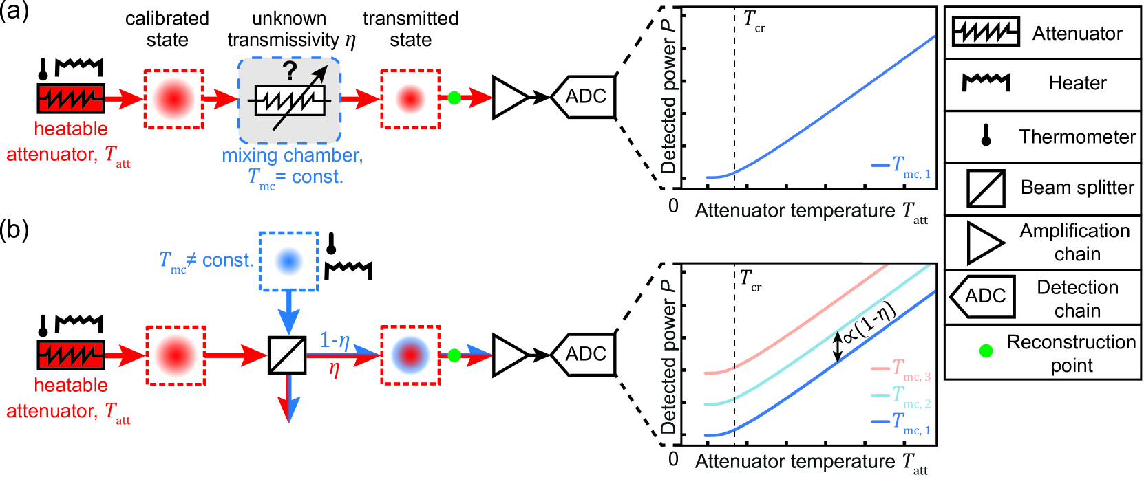
Figure 1(a) shows the experimental scheme for the conventional Planck spectroscopy, which is based on a reference black-body radiator as calibrated photon source embedded into the cryogenic system. In our experiments, we use a heatable cryogenic microwave attenuator as a self-calibrated photon source. Compared to other approaches, the use of a black-body radiator is experimentally advantageous, as it is very robust to imperfections and requires only a minimal number of additional experimental elements, such as a heater and calibrated thermometer. The microwave power emitted by the attenuator stabilized at a temperature follows Planck’s law
| (1) |
where is the Planck constant, is the Boltzmann constant, is the carrier frequency, and is the full detection bandwidth. For high attenuator temperatures, this expression reduces to the classical Johnson-Nyquist relation for the thermal noise power, . To quantify the onset of this linear regime, we introduce the cross-over temperature [34]. It marks the intersection between the constant asymptotic behavior of Eq. (1) in the low temperature limit and the linear asymptotic dependence in the high temperature limit. For a carrier frequency of , we have .
In many experiments, it is essential to reconstruct quantum states at a particular location within the experimental set-up rather than directly at the heatable attenuator output, as illustrated in Fig. 1(a). This requires a careful calibration of the detection chain relative to a specific reconstruction point, as states at the reconstruction point are related to those at the heatable attenuator via the power transmissivity . The conventional Planck spectroscopy lacks the ability to simultaneously calibrate both the detection chain and transmissivity . While one can estimate the transmissivity value from individual datasheets of the respective microwave components, or rely on reflectometry measurements at room temperature to estimate impedance mismatches, an accurate prediction of the resulting losses at millikelvin temperatures is generally challenging due to different temperature dependencies of the properties of various components.
In order to experimentally determine the transmissivity , we introduce the two-dimensional Planck spectroscopy by sweeping two independent temperatures, namely the environmental temperature, which is provided by the mixing chamber temperature of the commercial dilution croystat housing the experiment, and the heatable attenuator temperature . The corresponding experimental scheme is shown in Fig. 1(b). Here, we consider all lossy microwave components as 4-port devices and describe signal losses using a single, asymmetric beam splitter with associated power transmissivity . Thus, signals incident at the input of this fictitious beam splitter are attenuated and a thermal state, with a mean photon number corresponding to the environmental temperature , couples to the microwave channel. Respectively, the microwave power measured at room temperature at the end of the amplification chain is given by
| (2) |
where is the photon number conversion factor (PNCF). This proportionality factor relates the power measured at room temperature to the photon number at the desired reference point in the cryogenic set-up and depends on the bandwidth, the carrier frequency and the amplification gain. Furthermore, is the number of noise photons added by our amplification chain, stemming to a large extent from a cryogenic high-electron mobility transistor (HEMT) amplifier during initial amplification of the signal. Due to typically high gain values of the microwave HEMT amplifiers (), we can neglect the noise contribution from the cascaded room temperature amplifiers [35]. Lastly, corresponds to the characteristic impedance of our microwave circuits. The quantity can be interpreted as the detected power per microwave photon.
Analysis of the structure of Eq. (2) immediately provides an intuition for the working principle of the two-dimensional Planck spectroscopy. It becomes apparent that one can change the microwave power measured at room temperature, , in-situ by two means, namely by either changing the attenuator temperature, , or the temperature of the environment, . We first analyze the power difference, , measured at room temperature at the end of the amplification chain for two different temperature values of the mixing chamber, , while we stabilize the heatable attenuator at a constant temperature. For environment temperatures well above the cross-over temperature , the noise power can be substituted in good approximation with the linear Johnson-Nyquist dependence. In this case, we find
| (3) |
where . Equation (3) illustrates the fact that we can accurately estimate the unknown transmissivity by measuring vertical spacing between different conventional Planck spectroscopy curves shown in Fig. 1(b). By extending this method to, at least, three different mixing chamber temperatures we can additionally investigate a potential temperature dependence of .
III Experimental results
III.1 Experimental set-up
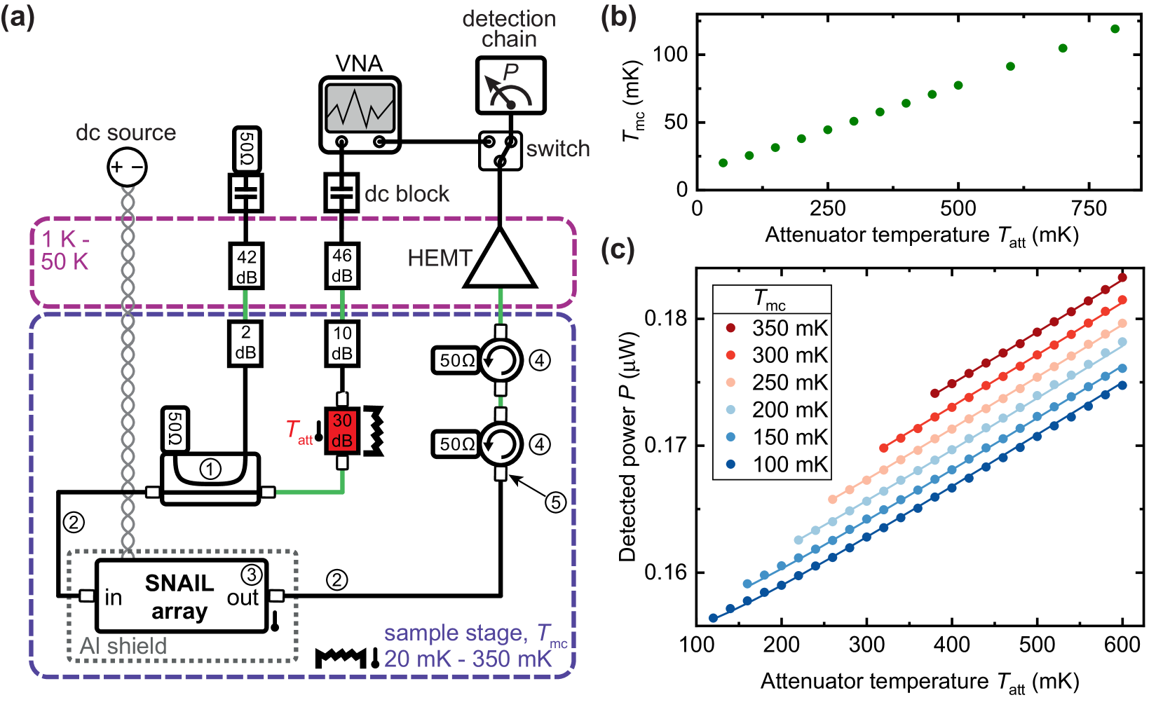
Our experimental set-up consists of a flux-tunable superconducting circuit serially connected to a cryogenic HEMT amplifier (Low Noise Factory LNF-LNC4_8C). The superconducting circuit is made from a coplanar transmission line with an array of SNAILs (Superconducting Nonlinear Asymmetric Inductive eLement) which forms a flux-tunable microwave waveguide [36, 20]. We use this system to vary the overall attenuation through the microwave channel. At the carrier frequency of , the metamaterial introduces around of internal losses [20]. A detailed scheme of the experimental set-up is shown in Fig. 2(a). Except for the HEMT amplifier, all of the cryogenic microwave components are thermally coupled to the mixing chamber plate of the dilution cryostat using high purity, annealed silver wires. The heatable attenuator is located at the input of the sample stage. A resistor, serving as a heater, and a RuO2 thermometer attached to this attenuator allow for stabilization of its temperature using a PID control loop realized with an external Picowatt AVS-48SI Picobridge resistance bridge. We use a stainless steel input cable and a superconducting NbTi/NbTi coaxial cable after the heatable attenuator. At a temperature of , the thermal conductivity of NbTi and stainless steel are [37] and [15], respectively. Both coaxial cables are based on polytetrafluoroethylene (PTFE) as the dielectric material. In this temperature regime, the contribution to the thermal conductivity stemming from the PTFE amounts to [38, 17]. Due to the low overall thermal conductivity of both coaxial microwave cables, we use an additional thinned silver ribbon to weakly couple the heatable attenuator to the mixing chamber plate. This allows us to balance a heat load applied to the dilution fridge during temperature sweeps. While the thermal conductivity of this silver ribbon sensitively depends on the purity of the material and the annealing process [15], we conservatively estimate . Consequently, the thermalization of the heatable attenuator is determined by the heat conductivity of the silver ribbon. The temperature of the mixing chamber plate is stabilized using a second PID control loop based on a Lakeshore Model 372 AC Resistance Bridge. A thermometer mounted to the sample holder containing the SNAIL metamaterial allows us to verify a homogeneous temperature distribution between the mixing chamber plate and the sample holder. We use a heterodyne microwave receiver at room temperature as well as a subsequent digital data processing set-up, similar to the one described in Ref. [11]. Here, the signal is filtered around the carrier frequency of and down-converted to an intermediate frequency (IF) of using an image rejection mixer. Before and after the down-conversion process, the signal is amplified with multiple amplifiers at room temperature. The signal is digitized with an analog-to-digital converter, digitally down-converted and filtered within a full bandwidth of around the desired carrier frequency using a finite-impulse response (FIR) filter. For the last step, the second order quadrature moments and , quantifying the signal power, are calculated. All of the aforementioned digital data processing steps are performed with a field-programmable gate array (FPGA).
III.2 Measurement results
First, we measure the dependence of on the attenuator temperature . Here, we sweep the temperature of the heatable attenuator, , and measure the steady-state temperatures of the mixing chamber plate, . The result of this measurement is shown in Fig. 2(b). We conclude that the attenuator can only be heated up to , as long as we want to stabilize the mixing chamber plate at . For the two-dimensional Planck spectroscopy we perform six consecutive sweeps of the attenuator temperature, while increasing the mixing chamber temperature in steps of , starting from . For each step, the lowest heatable attenuator temperature is set 20- higher than the present mixing chamber temperature to ensure sufficient temperature stabilization within of the desired value. Figure 2(c) shows the resulting experimental data. All six experimental Planck curves are simultaneously fitted with a weighted least-square fit, according to Eq. (2). The weights for each Planck curve are chosen inversely proportional to the respective number of data points. Furthermore, the aforementioned calibration procedure enables us to treat and as independent control quantities. The measured data shows an approximately equidistant spacing between the different mixing chamber temperatures, as expected from Eq. (3). This indicates a constant transmissivity in the temperature range up to . For this fit, we employ , , and as fit parameters and observe a good agreement between the measured and fitted data for , , and microwave losses . The number of HEMT amplifier noise photons measured with the two-dimensional Planck spectroscopy is in good agreement with the datasheet value of . At the carrier frequency of , we can also estimate the signal losses based on the datasheet values of individual components. The contributions of respective microwave components are listed in the caption of Fig. 2(a) and we obtain . We observe that the path loss obtained with the two-dimensional Planck spectroscopy is roughly larger than the value estimated from the datasheet numbers.
The PNCF is a fundamental quantity for reconstruction of quantum states [28, 39, 11, 10] and slight deviations in its value might have a drastic impact on the properties of the reconstructed quantum states. In order to investigate the effect of underestimating losses, as it is the case when using the values provided by the datasheets, we can compare the PNCF obtained from the two-dimensional Planck spectroscopy, , to the one derived from a conventional, one-dimensional, Planck spectroscopy, . To this end, we can evaluate the data measured at the fixed mixing chamber temperature of and use the fitting routine according to Eq. (2), but with a fixed bath temperature, corresponding to the conventional Planck calibration. In this way, we do not obtain any information about the unknown transmissivity, , present in the propagation path of the signal and have to rely on the datasheet value of . This underestimation of losses, as compared to the two-dimensional Planck spectroscopy, directly leads to an overestimation of both and . Specifically, we obtain values of and . Here, it is important to note that we only measure an effective noise photon number which is scaled by the inverse transmissivity.
Now, we can consider a hypothetical reconstruction experiment of a squeezed vacuum state, a quantum state commonly used in many experiments [39, 11, 40, 3, 41, 5], based on the PNCF values obtained with both methods. Quantum state parameters, which are often used to describe the properties of these states, are the squeezing level , defined as a suppression of the squeezed signal quadrature variance below the vacuum level, [42], and the purity , which quantifies deviation from the Heisenberg limit and thus an amount of classical noise (mixedness) in the reconstructed quantum state [11]. Assuming the hypothetical squeezed state with a squeezing level of and purity of obtained with the help of the two-dimensional Planck spectroscopy, the same state will be reconstructed with the squeezing level and purity of , when using the the PNCF from the conventional Planck spectroscopy. This highlights the difference between the two calibration methods as well as the importance of precise knowledge of both the PNCF and losses present in the system for the precise quantum state tomography.
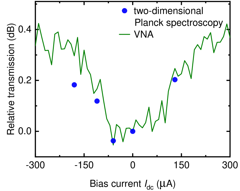
We can further explore the potential of in-situ loss measurement via the two-dimensional Planck spectroscopy by utilizing the Josephson metamaterial as a flux-tunable attenuator. To this end, we vary the SNAIL flux bias by changing the current, , through the on-chip bias line. First, we measure the transmitted power through the system using a vector network analyzer (VNA). Such measurements cannot be used to estimate the absolute losses in individual subsystems, but provide useful information about a relative change of losses. To this end, we start by performing an amplitude reference measurement at zero flux bias and the carrier frequency of , , with an IF bandwidth of . Then, we calculate the change of losses as a function of bias current, . Subsequently, we perform multiple two-dimensional Planck measurements at different flux biases and use the fitting routine according to Eq. (2) to extract the loss values . As before, we take the result at zero flux bias, as a reference and only consider the change of loss with respect to this value. Figure 3 shows the result of this procedure. We observe good agreement between both methods. The two-dimensional Planck spectroscopy is able to resolve loss changes smaller than in our experimental set-up. For SNAIL bias currents below , the change in attenuation is smaller than expected from the VNA measurements. This deviation may be a result of substantially different measurement bandwidths used in the two methods: while the VNA probes a narrow bandwidth of , the two-dimensional Planck spectroscopy bandwidth is defined by a digital FPGA filter with a bandwidth of . Respectively, many microwave components, such as circulators or the SNAIL metamaterial, may have a weakly frequency-dependent power loss spectrum [20]. Consequently, this frequency dispersion may lead to deviations of estimated losses when using measurements with different effective bandwidths.
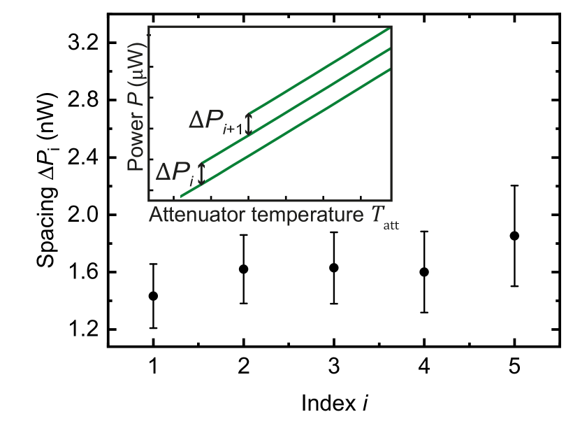
Next, we take a closer look at the temperature dependence of the channel transmissivity, , obtained with the two-dimensional Planck spectroscopy. Figure 4 shows the spacing between the Planck curves measured at two adjacent mixing chamber temperatures, extracted from Fig. 2(c). The index corresponds to the spacing between Planck curves measured at mixing chamber temperatures of and . According to Eq.(3), this spacing allows to investigate a temperature dependence of the channel transmissivity. We observe that the curves corresponding to the highest mixing chamber plate temperatures, and , show a spacing that is slightly increased in comparison to the lower temperatures. Consequently, these results indicate an approximately constant transmissivity up to a mixing chamber temperature of 300 mK, followed by a subsequent decrease in transmissivity. We attribute this decrease in transmissivity to the temperature-dependent resistance in normal conducting materials in cryogenic circulators [43] or to a possible formation of quasiparticles in the superconducting sample [44, 45]. We note that the two-dimensional Planck spectroscopy enables the distinction between temperature-dependent and temperature-independent losses. Furthermore, we can quantify this temperature dependence and take it into account for the reconstruction of quantum states at elevated temperatures. For future experiments, one could also apply the two-dimensional Planck spectroscopy as a tool to investigate a genuine noise temperature of a device, as for many systems, an actual electronic temperature may differ from a phononic temperature. This effect is related to microwave dissipation and excitation of the so-called ‘hot electrons’ and the weak coupling of the electronic to the phononic system at low temperatures [46, 47, 48].
IV Conclusion
We have demonstrated an experimental implementation of the two-dimensional Planck spectroscopy allowing for an in-situ calibration of microwave losses, as well as for an accurate estimation of photon conversion coefficients in a cryogenic set-up. To this end, we have extended the conventional Planck spectroscopy approach [19] by adding the second degree of freedom in the form of variable temperature of the whole cryogenic environment (the mixing chamber temperature). We have employed a beam splitter loss model to describe and extract an unknown transmissivity (losses) from the two-dimensional Planck spectroscopy measurements, and thus, improve the calibration accuracy. Furthermore, our approach has enabled us to directly assess the temperature dependence of microwave losses. In our experiments, we have observed a good agreement between the measured data and fitted theory model. Moreover, we have employed a Josephson metamaterial sample as a flux-tunable attenuator to benchmark the accuracy of the two-dimensional Planck spectroscopy and demonstrated that we are able to resolve microwave loss changes down to .
Our calibration technique relies on using heatable attenuators as broadband black-body photon sources and can be used in a large variety of modern cryogenic experiments, including the characterization of cryogenic HEMT amplifiers, quantum-limited parametric amplifiers, and other superconducting devices. Its inherent ability to determine internal signal losses allows for a more precise estimation of the noise performance of the aforementioned devices. We envision important applications of this method in experiments that rely on the efficient detection of signal amplitudes, such as the search for dark matter axions [31], where the precise knowledge of noise figures is a key prerequisite. Furthermore, it can also serve as an important tool for characterization of various qubit readout schemes.
V Acknowledgments
We acknowledge support by the German Research Foundation via Germany’s Excellence Strategy (EXC2111-390814868), the German Federal Ministry of Education and Research via the project QUARATE (Grant No.13N15380). This research is part of the Munich Quantum Valley, which is supported by the Bavarian state government with funds from the Hightech Agenda Bayern Plus. We acknowledge Joonas Govenius and VTT Technical Research Centre of Finland Ltd. for providing the SNAIL-based superconducting metamaterial sample.
References
- Clerk et al. [2010] A. A. Clerk, M. H. Devoret, S. M. Girvin, F. Marquardt, and R. J. Schoelkopf, Introduction to quantum noise, measurement, and amplification, Rev. Mod. Phys. 82, 1155 (2010).
- Menzel et al. [2012] E. P. Menzel, R. Di Candia, F. Deppe, P. Eder, L. Zhong, M. Ihmig, M. Haeberlein, A. Baust, E. Hoffmann, D. Ballester, K. Inomata, T. Yamamoto, Y. Nakamura, E. Solano, A. Marx, and R. Gross, Path entanglement of continuous-variable quantum microwaves, Phys. Rev. Lett. 109, 250502 (2012).
- Eichler et al. [2011] C. Eichler, D. Bozyigit, C. Lang, M. Baur, L. Steffen, J. M. Fink, S. Filipp, and A. Wallraff, Observation of two-mode squeezing in the microwave frequency domain, Phys. Rev. Lett. 107, 113601 (2011).
- Di Candia et al. [2014] R. Di Candia, E. P. Menzel, L. Zhong, F. Deppe, A. Marx, R. Gross, and E. Solano, Dual-path methods for propagating quantum microwaves, New J. Phys. 16, 015001 (2014).
- Flurin et al. [2012] E. Flurin, N. Roch, F. Mallet, M. H. Devoret, and B. Huard, Generating entangled microwave radiation over two transmission lines, Phys. Rev. Lett. 109, 183901 (2012).
- Schneider et al. [2020] B. H. Schneider, A. Bengtsson, I. M. Svensson, T. Aref, G. Johansson, J. Bylander, and P. Delsing, Observation of roadband ntanglement in icrowave adiation from a ingle ime-arying oundary ondition, Phys. Rev. Lett. 124, 140503 (2020).
- Kurpiers et al. [2018] P. Kurpiers, P. Magnard, T. Walter, B. Royer, M. Pechal, J. Heinsoo, Y. Salathé, A. Akin, S. Storz, J.-C. Besse, S. Gasparinetti, A. Blais, and A. Wallraff, Deterministic quantum state transfer and remote entanglement using microwave photons, Nature 558, 264 (2018).
- Bienfait et al. [2019] A. Bienfait, K. J. Satzinger, Y. P. Zhong, H.-S. Chang, M.-H. Chou, C. R. Conner, É. Dumur, J. Grebel, G. A. Peairs, R. G. Povey, and A. N. Cleland, Phonon-mediated quantum state transfer and remote qubit entanglement, Science 364, 368 (2019).
- Magnard et al. [2020] P. Magnard, S. Storz, P. Kurpiers, J. Schär, F. Marxer, J. Lütolf, T. Walter, J.-C. Besse, M. Gabureac, K. Reuer, A. Akin, B. Royer, A. Blais, and A. Wallraff, Microwave uantum ink between uperconducting ircuits oused in patially eparated ryogenic ystems, Phys. Rev. Lett. 125, 260502 (2020).
- Pogorzalek et al. [2019] S. Pogorzalek, K. G. Fedorov, M. Xu, A. Parra-Rodriguez, M. Sanz, M. Fischer, E. Xie, K. Inomata, Y. Nakamura, E. Solano, A. Marx, F. Deppe, and R. Gross, Secure quantum remote state preparation of squeezed microwave states, Nat. Commun. 10, 2604 (2019).
- Fedorov et al. [2021] K. G. Fedorov, M. Renger, S. Pogorzalek, R. Di Candia, Q. Chen, Y. Nojiri, K. Inomata, Y. Nakamura, M. Partanen, A. Marx, R. Gross, and F. Deppe, Experimental quantum teleportation of propagating microwaves, Sci. Adv. 7, eabk0891 (2021).
- Blais et al. [2004] A. Blais, R.-S. Huang, A. Wallraff, S. M. Girvin, and R. J. Schoelkopf, Cavity quantum electrodynamics for superconducting electrical circuits: n architecture for quantum computation, Phys. Rev. A 69, 062320 (2004).
- Krantz et al. [2019] P. Krantz, M. Kjaergaard, F. Yan, T. P. Orlando, S. Gustavsson, and W. D. Oliver, A quantum engineer’s guide to superconducting qubits, Appl. Phys. Rev. 6, 021318 (2019).
- Schoelkopf et al. [2003] R. J. Schoelkopf, A. A. Clerk, S. M. Girvin, K. W. Lehnert, and M. H. Devoret, Qubits as pectrometers of uantum oise, in Quantum Noise in Mesoscopic Physics, edited by Y. V. Nazarov (Springer Netherlands, Dordrecht, 2003) pp. 175–203.
- Pobell [1996] F. Pobell, Matter and methods at low temperatures, 2nd ed. (Springer-Verlag, Berlin, 1996).
- Giordano et al. [1975] S. Giordano, H. Hahn, H. Halama, T. Luhman, and W. Bauer, Investigation of microwave properties of superconducting 0.40.6, IEEE Trans. Magn. 11, 437 (1975).
- Kushino et al. [2008] A. Kushino, S. Kasai, S. Kohjiro, S. Shiki, and M. Ohkubo, Development of uperconducting oaxial ables for ryogenic etectors, J. Low Temp. Phys. 151, 650 (2008).
- Kurpiers et al. [2017] P. Kurpiers, T. Walter, P. Magnard, Y. Salathe, and A. Wallraff, Characterizing the attenuation of coaxial and rectangular microwave-frequency waveguides at cryogenic temperatures, EPJ Quantum Technol. 4, 8 (2017).
- Mariantoni et al. [2010] M. Mariantoni, E. P. Menzel, F. Deppe, M. A. Araque Caballero, A. Baust, T. Niemczyk, E. Hoffmann, E. Solano, A. Marx, and R. Gross, Planck spectroscopy and quantum noise of microwave beam splitters, Phys. Rev. Lett. 105, 133601 (2010).
- Perelshtein et al. [2022] M. R. Perelshtein, K. V. Petrovnin, V. Vesterinen, S. Hamedani Raja, I. Lilja, M. Will, A. Savin, S. Simbierowicz, R. N. Jabdaraghi, J. S. Lehtinen, L. Grönberg, J. Hassel, M. P. Prunnila, J. Govenius, G. S. Paraoanu, and P. J. Hakonen, Broadband ontinuous-ariable ntanglement eneration sing a err-ree osephson etamaterial, Phys. Rev. Appl. 18, 024063 (2022).
- Simbierowicz et al. [2021] S. Simbierowicz, V. Vesterinen, J. Milem, A. Lintunen, M. Oksanen, L. Roschier, L. Grönberg, J. Hassel, D. Gunnarsson, and R. E. Lake, Characterizing cryogenic amplifiers with a matched temperature-variable noise source, Rev. Sci. Instrum. 92, 034708 (2021).
- Jebari et al. [2018] S. Jebari, F. Blanchet, A. Grimm, D. Hazra, R. Albert, P. Joyez, D. Vion, D. Estève, F. Portier, and M. Hofheinz, Near-quantum-limited amplification from inelastic ooper-pair tunnelling, Nat. Electron. 1, 223 (2018).
- Spietz et al. [2003] L. Spietz, K. W. Lehnert, I. Siddiqi, and R. J. Schoelkopf, Primary electronic thermometry using the shot noise of a tunnel junction, Science 300, 1929 (2003).
- Roy and Devoret [2018] A. Roy and M. Devoret, Quantum-limited parametric amplification with osephson circuits in the regime of pump depletion, Phys. Rev. B 98, 045405 (2018).
- Qiu et al. [2023] J. Y. Qiu, A. Grimsmo, K. Peng, B. Kannan, B. Lienhard, Y. Sung, P. Krantz, V. Bolkhovsky, G. Calusine, D. Kim, A. Melville, B. M. Niedzielski, J. Yoder, M. E. Schwartz, T. P. Orlando, I. Siddiqi, S. Gustavsson, K. P. O’Brien, and W. D. Oliver, Broadband squeezed microwaves and amplification with a osephson travelling-wave parametric amplifier, Nat. Phys 19, 706–713 (2023).
- Macklin et al. [2015] C. Macklin, K. O’Brien, D. Hover, M. E. Schwartz, V. Bolkhovsky, X. Zhang, W. D. Oliver, and I. Siddiqi, A near-quantum-limited osephson traveling-wave parametric amplifier, Science 350, 307 (2015).
- Hönigl-Decrinis et al. [2020] T. Hönigl-Decrinis, R. Shaikhaidarov, S. de Graaf, V. Antonov, and O. Astafiev, Two-evel ystem as a uantum ensor for bsolute alibration of ower, Phys. Rev. Appl. 13, 024066 (2020).
- Renger et al. [2021] M. Renger, S. Pogorzalek, Q. Chen, Y. Nojiri, K. Inomata, Y. Nakamura, M. Partanen, A. Marx, R. Gross, F. Deppe, and K. G. Fedorov, Beyond the standard quantum limit for parametric amplification of broadband signals, NPJ Quantum Inf. 7, 160 (2021).
- Pozar [2012] D. M. Pozar, Microwave engineering, 4th ed. (New York and John Wiley and Sons Ltd, 2012).
- Heinz et al. [2022] F. Heinz, F. Thome, A. Leuther, and O. Ambacher, A ryogenic n-hip oise easurement rocedure ith ±1.4 easurement ncertainty, in 2022 IEEE MTT-S Int. Microw. Symp Dig. (2022) pp. 233–236.
- Bartram et al. [2023] C. Bartram, T. Braine, R. Cervantes, N. Crisosto, N. Du, G. Leum, P. Mohapatra, T. Nitta, L. J. Rosenberg, G. Rybka, J. Yang, J. Clarke, I. Siddiqi, A. Agrawal, A. V. Dixit, M. H. Awida, A. S. Chou, M. Hollister, S. Knirck, A. Sonnenschein, W. Wester, J. R. Gleason, A. T. Hipp, S. Jois, P. Sikivie, N. S. Sullivan, D. B. Tanner, E. Lentz, R. Khatiwada, G. Carosi, C. Cisneros, N. Robertson, N. Woollett, L. D. Duffy, C. Boutan, M. Jones, B. H. LaRoque, N. S. Oblath, M. S. Taubman, E. J. Daw, M. G. Perry, J. H. Buckley, C. Gaikwad, J. Hoffman, K. Murch, M. Goryachev, B. T. McAllister, A. Quiskamp, C. Thomson, M. E. Tobar, V. Bolkhovsky, G. Calusine, W. Oliver, and K. Serniak, Dark matter axion search using a osephson raveling wave parametric amplifier, Rev. Sci. Instrum. 94, 044703 (2023).
- Eddins et al. [2019] A. Eddins, J. M. Kreikebaum, D. M. Toyli, E. M. Levenson-Falk, A. Dove, W. P. Livingston, B. A. Levitan, L. C. G. Govia, A. A. Clerk, and I. Siddiqi, High-efficiency easurement of an rtificial tom mbedded in a arametric mplifier, Phys. Rev. X 9, 011004 (2019).
- Lasenby [2020] R. Lasenby, Microwave cavity searches for low-frequency axion dark matter, Phys. Rev. D 102, 015008 (2020).
- Mariantoni [2009] M. Mariantoni, New trends in superconducting circuit quantum electrodynamics: two amplifiers, two resonators, and two photons, Ph.. thesis, Technische Universität München (2009).
- Friis [1944] H. T. Friis, Noise igures of adio eceivers, Proc. IRE 32, 419 (1944).
- Frattini et al. [2017] N. E. Frattini, U. Vool, S. Shankar, A. Narla, K. M. Sliwa, and M. H. Devoret, 3-wave mixing osephson dipole element, Appl. Phys. Lett. 110, 222603 (2017).
- Olson [1993] J. Olson, Thermal conductivity of some common cryostat materials between 0.05 and K, Cryogenics 33, 729 (1993).
- Drobizhev et al. [2017] A. Drobizhev, J. Reiten, V. Singh, and Y. G. Kolomensky, Thermal conductivity measurements of and 23 ceramic at sub-kelvin temperatures, Cryogenics 85, 63 (2017).
- Fedorov et al. [2016] K. G. Fedorov, L. Zhong, S. Pogorzalek, P. Eder, M. Fischer, J. Goetz, E. Xie, F. Wulschner, K. Inomata, T. Yamamoto, Y. Nakamura, R. Di Candia, U. Las Heras, M. Sanz, E. Solano, E. P. Menzel, F. Deppe, A. Marx, and R. Gross, Displacement of propagating squeezed microwave states, Phys. Rev. Lett. 117, 020502 (2016).
- Malnou et al. [2018] M. Malnou, D. A. Palken, L. R. Vale, G. C. Hilton, and K. W. Lehnert, Optimal peration of a osephson arametric mplifier for acuum queezing, Phys. Rev. Appl. 9, 044023 (2018).
- Mallet et al. [2011] F. Mallet, M. A. Castellanos-Beltran, H. S. Ku, S. Glancy, E. Knill, K. D. Irwin, G. C. Hilton, L. R. Vale, and K. W. Lehnert, Quantum state tomography of an itinerant squeezed microwave field, Phys. Rev. Lett. 106, 220502 (2011).
- Zhong et al. [2013] L. Zhong, E. P. Menzel, R. Di Candia, P. Eder, M. Ihmig, A. Baust, M. Haeberlein, E. Hoffmann, K. Inomata, T. Yamamoto, Y. Nakamura, E. Solano, F. Deppe, A. Marx, and R. Gross, Squeezing with a flux-driven osephson parametric amplifier, New J. Phys. 15, 125013 (2013).
- Allen [1956] P. J. Allen, The urnstile irculator, IEEE Trans. Microw. Theory Tech. 4, 223 (1956).
- Aumentado et al. [2004] J. Aumentado, M. W. Keller, J. M. Martinis, and M. H. Devoret, Nonequilibrium quasiparticles and 2e periodicity in single-ooper-pair transistors, Phys. Rev. Lett. 92, 066802 (2004).
- Wilson and Prober [2004] C. M. Wilson and D. E. Prober, Quasiparticle number fluctuations in superconductors, Phys. Rev. B 69, 094524 (2004).
- Roukes et al. [1985] M. L. Roukes, Freeman, R. S. Germain, R. C. Richardson, and M. B. Ketchen, Hot electrons and energy transport in metals at millikelvin temperatures, Phys. Rev. Lett. 55, 422 (1985).
- Wellstood et al. [1994] F. C. Wellstood, C. Urbina, and J. Clarke, Hot-electron effects in metals, Phys. Rev. B 49, 5942 (1994).
- Yeh et al. [2019] J.-H. Yeh, Y. Huang, R. Zhang, S. Premaratne, J. LeFebvre, F. C. Wellstood, and B. S. Palmer, Hot electron heatsinks for microwave attenuators below mK, Appl. Phys. Lett. 114, 152602 (2019).