A Compliant Robotic Leg Based on
Fibre Jamming
Abstract
Humans possess a remarkable ability to react to sudden and unpredictable perturbations through immediate mechanical responses, which harness the visco-elastic properties of muscles to perform auto-corrective movements to maintain balance. In this paper, we propose a novel design of a robotic leg inspired by this mechanism. We develop multi-material fibre jammed tendons, and demonstrate their use as passive compliant mechanisms to achieve variable joint stiffness and improve stability. Through numerical simulations and extensive experimentation, we demonstrate the ability for our system to achieve a wide range of potentially beneficial compliance regimes. We show the role and contribution of each tendon quantitatively by evaluating their individual force contribution in resisting rotational perturbations. We also perform walking experiments with programmed bioinspired gaits that varying the stiffness of the tendons throughout the gait cycle, demonstrating a stable and consistent behaviour. We show the potential of such systems when integrated into legged robots, where compliance and shock absorption can be provided entirely through the morphological properties of the leg.
Index Terms:
Soft robotics, compliant mechanisms, mechanism design, fibre jamming, legged robotics.I Introduction
Legged robotics is a rapidly evolving field, with recent applications ranging from search-and-rescue operations [1] to the exploration of complex and unstructured environments[2, 3]. However, despite significant advances in the research of legged robotics, developing a closed-loop control system that involves feedback from sensors to actively control the trajectory of the leg remains a challenge for researchers. This is largely due to the unpredictability and varying nature of real-world terrains, which cannot be wholly accounted for or pre-planned in the control design of a robotic system. Hence, there is a push for robots to be able to handle unexpected events with minimal sensory feedback and control. One approach to addressing these challenges is to implement morphologically intelligent structures, which allow robotic legs to passively adapt to changing terrains and unexpected perturbations through its material makeup, similarly to how humans are able to perform ”preflexes”, an auto-corrective movement response, provided by the passive tension of the muscles. Preflexes play an important role in the dynamic stability of both humans and animals, and this is enabled by the intrinsic mechanical properties in the muscles [4, 5]. Muscles, are visco-elastic in nature and are able to passively perform perturbation rejection almost instantly when there is a change in length[6]. This is especially useful in unforeseeable situations such as falling into a hole or tripping on a curb, where the foot in unexpectedly stretched up or down.
Robotic legs are typically comprised of rigid elements connected by stiff joints. However, in reality, nature’s design tends to favour more soft materials and yet, they are able to perform robustly in the harshest of environments. Even stiff structures such as bones, are surrounded by soft tissues like muscles and tendons. While rigid structures offer more precise control and have greater load bearing, and force transmission capabilities, soft structures allow passive adaptation to the environment and protect the system from mechanical damage. By harnessing the benefits of soft robotics, we could enable rigid systems with capabilities that cannot be attained through traditional rigid elements. Hence, this resulted in the emergence of articulated soft systems, which combines the controllability of rigid structures with the flexibility of compliant structures [7]. Researchers have long exploited this paradigm to create robotic systems that can better adapt and perform in various environments. By bridging the gap between rigid and soft robotics, we open up new possibilities for more morphologically intelligent and versatile designs.
Compliance in legged robots can be achieved through various techniques, including Pneumatic Artificial Muscles (PAM)[8, 9, 10, 11, 12], Series Elastic Actuators (SEA) [13, 14] and by integrating passive elastic elements into the leg’s mechanism [15, 16, 17]. PAMs have been commonly used by researchers in the past due to their high strength-to-weight ratio [8]. However, non-linearities within the structure presents a perennial challenge to researchers trying to control this dynamic behaviour via pressure [8]. Elastic elements or mechanical springs, on the other hand, are a much more popular choice due to their ease of implementation and modelling. However, these springs have limited tunability due to their fixed linear stiffness and consequently, are unlikely to be able to handle a variety of different loading conditions, as one would experience when traversing diverse natural environments. Furthermore, selection of these springs were traditionally based on designers intuition or by estimations from experimental human locomotion data [18].
In this work we focus on a third promising technique, jamming [19, 20], and study its role in the creation of compliant robotic legs. Jamming has to date been relatively understudied for this application. Due to the potential for rapid, high-range stiffness variation, jammed structures have shown promise in related works, e.g., to achieve variable stiffness in wearables, such as exoskletons [21] or as a friction based locking mechanisms for revolute joints[22]. There are three main jamming technologies available to us; granular, layer, and fibre jamming. Granular jamming, which consists of grains sealed in an air-tight membrane, is by far the most popular method used to achieve a variable stiffness structure[19]. Under compression, a large variation in stiffness can be achieved and hence, researchers in the past have exploited this mechanical property to improve foot adaptability in various terrains [23, 24, 25]. However, these adaptive feet are often made from delicate soft materials, such as latex or textile membranes filled with granular material, which are prone to wear in rough environments. Furthermore, when a torsional or bending force is applied, grains tend to slip and can result in unfavourable configurations, making it less appropriate to be used in revolute joints, as it may inhibit their motion. The non-homogeneous distribution of grains can lead to variable mechanical properties across the structure and consequently, making it difficult for researchers to quantify the structural stiffness. As well as granular jamming, recent years have seen developments in alternate jamming mechanisms including layer and fibre jamming. Layer jamming structures are by far the least deformable [19] and their stiffness is highly dependent on planar orientation of the layers. This limits the number of DOF on a joint and any motion that is out of plane may introduce unwanted stiffness or result in buckling, which is undesirable in legged locomotion.
Fibre jamming, on the other hand, offers a low bending stiffness in the two orthogonal directions to the axis of the fibres (the radial direction) is ideal to allow freedom-of-movement of the rotational joints in the leg [26]. Fibre Jammed Structures (FJS) utilise bundles of longitudinal fibres fixed at both ends in a system enclosed within a sealed membrane[27, 28, 26, 29, 30]. These flexible fibres are free to slide across each other and thus, allowing low bending stiffness in all directions[28], which cannot be achieved by traditional granular and layer jamming methods. In their unjammed state, these fibres are free to rearrange against each other within the membrane. However, once vacuum pressure is applied, these fibres are constricted by the membrane and the structure becomes rigid.
Our previous work [31] introduced the 3D printed fibre jammed tendon unit, together with numerical and analytical methods to analyse its stiffness variability. In this paper, we significantly expand this fundamental work by (i) designing and fabricating a bespoke articulated soft robot leg that harnesses antagonistic tendon pairs for stable walking, (ii) performed a full characterisation of a multitude of aspects of performance in both FEA and experimentation, drawing links back to biology, and (iii) implemented a bioinspired walking strategy showing the potential of such articulated soft legs.
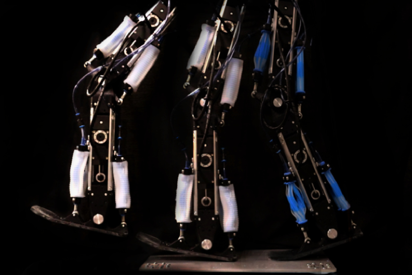
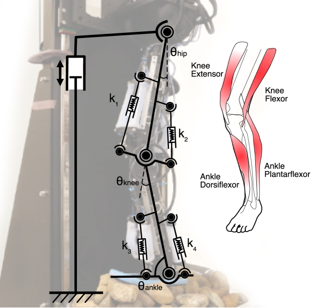
To the authors’ knowledge, the implementation of fibre jammed structures to achieve joint stiffness variability in legged robots have not thoroughly been investigated in literature, and previous focus was mainly in compliant jammed feet [32, 23, 24, 25]. This is largely due to the complexity in understanding the behaviour of these soft structures under constantly changing loading conditions, such as walking. To address this problem, we introduce a novel multibody compliant robotic leg, JEG (Jammed Leg) which incorporates fibre jammed tendons in an antagonistic arrangement to vary the stiffness of the knee and ankle joints (Fig.1). We mainly focus on introducing fibre jammed structures to mainly the knee and ankle, as they are known to be the primary shock absorbers during rapid loading of the leg[33, 34]. In contrast to traditional PAM robotic legs, which have to be actively controlled by varying pressure to the PAMs units, fibre jamming offers a simpler ‘two-state’ stiffness, allowing a base ‘unjammed’ stiffness when no vacuum is applied and a second stiffer ‘jammed’ stiffness when the tendons are jammed under a constant pressure. We demonstrate that by unjamming and jamming different combination of tendons, we can change and improve the leg’s resistive behaviour towards different perturbations. The JEG uses four monoarticular tendon bundles, with two sets of tendons placed in an antagonistic arrangement on each side of the knee joint and another two sets on each side of the ankle joint. The tendons are placed in this position to simulate major muscle-tendon groups, such as the hamstrings, quadriceps, shin and calve muscles.
The rest of the paper is organised as follows: Section II details the design of the fibre jammed leg—JEG. We first introduce the mechanical design of the robotic leg, followed by the integration of the fibre jammed tendons to the knee and ankle joints. We also provide details of the fabrication and characterisation of the multi-material tendons of varying fibre diameters and layers. In Section III, experimental data obtained from the tendon tensile characterisation tests were used in a multibody numerical Finite Element Model (FEM) to visualise the effects of jamming different tendons, and consequently the joint stiffness, on the kinematics and dynamics of the leg. This is followed by Section IV, which evaluates the role and contribution of each tendon pair towards attenuation of a rotational pitch perturbation. Section V assesses the walking performance of the JEG empirically by analysing the Ground Reaction Forces (GRF) for different jamming patterns using a force plate. In Section VI, we explore the results obtained in the experiments. Finally, we conclude the paper in Section VII with proposed future work and a discussion on limitations.
| Fibre Diameter (mm) | Layers | Mean Unjammed Force (SE) [N] | Mean Jammed Force (SE) [N] | Stiffness Change () |
| 1.5 | 3 | 13.1 (1.51) | 16.0 (2.85) | 1.22 |
| 4 | 23.6 (4.36) | 31.3 (2.74) | 1.32 | |
| 5 | 48.0 (2.58) | 68.0 (4.34) | 1.41 | |
| 2.0 | 3 | 20.5 (1.33) | 28.8 (2.04) | 1.40 |
| 4 | 46.9 (0.90) | 57.8 (2.63) | 1.23 | |
| 5 | 85.7 (2.26) | 106.7 (2.84) | 1.25 | |
| 2.5 | 3 | 34.7 (3.37) | 46.2 (3.43) | 1.33 |
| 4 | 67.4 (7.25) | 88.5 (10.24) | 1.31 | |
| 3.0 | 3 | 45.4 (4.18) | 64.7 (9.76) | 1.43 |
| 4 | 88.4 (7.84) | 102.7 (10.35) | 1.16 |
II Design of Fibre Jammed Leg
II-A Mechanical Design of the JEG
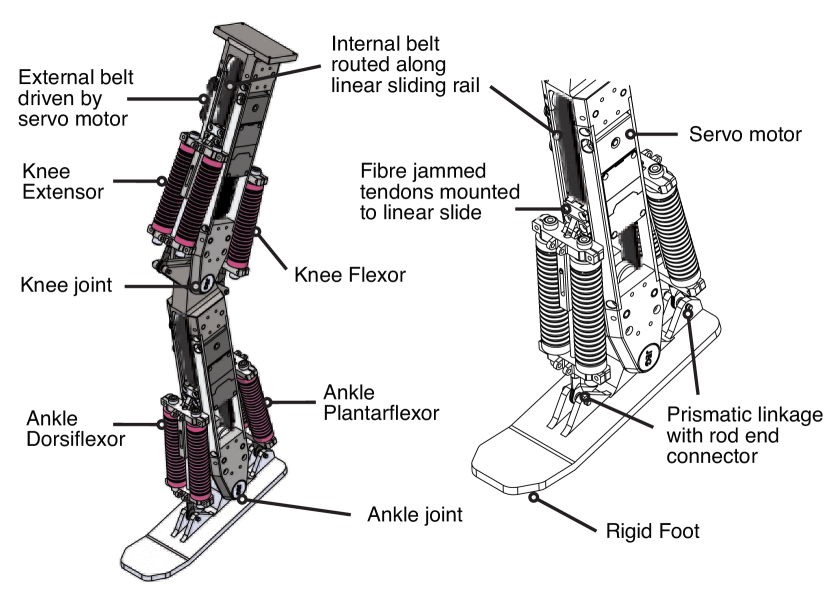
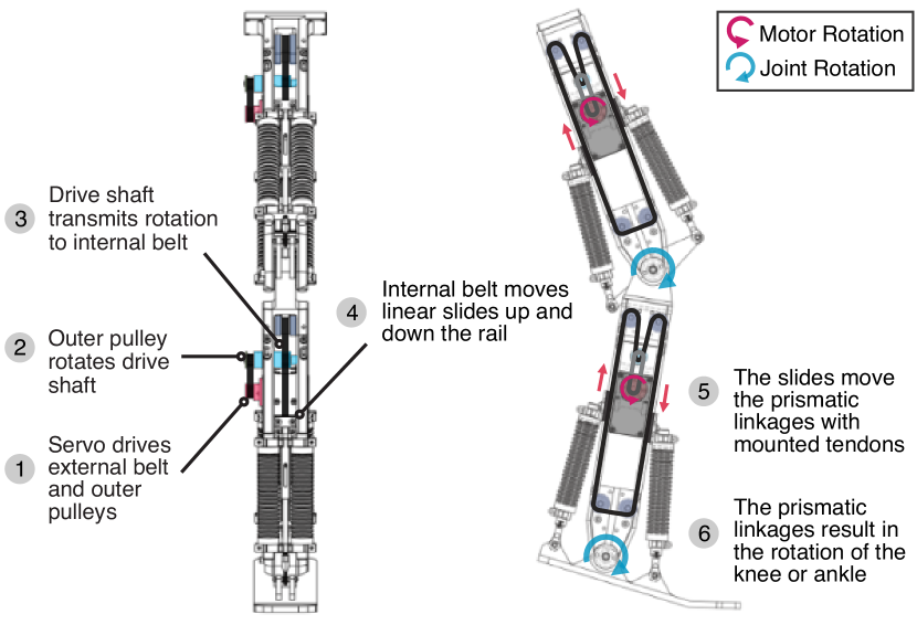
The JEG consists of three single Degree-Of-Freedom (DOF) rotational joints whose motion is constrained to the sagittal plane, as shown in Fig.2. The JEG has a hip joint for flexion-extension, knee joint for flexion-extension, and ankle joint for plantarflexion-dorsiflexion. The main body of the femur and tibia were constructed using aluminium frames, which act as linear rails, held together by 3D printed Acrylonitrile Styrene Acrylate (ASA) brackets. These brackets also act as revolute joints for the knee and ankle. The hip joint is actuated with a servo motor (ROBOTIS Dynamixel Pro H42-20-S300-R), while the knee and ankle joints are actuated using a timing belt transmission system with servo motors (ROBOTIS Dynamixel XM540-W270-T/R), which can produce torques of up to 12.9 Nm (stall torque at 14.8 V). Each servo drives an external belt connected to an outer-pulley, which is connected to the drive-shaft. The drive-shaft rotates the internal-pulley, which drives the internal belt. The design of the belt transmission system, along with routing path of the belt is shown in Fig.3.
Rotation of the knee and ankle joints are enabled by the prismatic motion of the telescopic shafts mounted in parallel to the joints, as demonstrated in Fig.3. Each of the four prismatic joints were constructed out of a machined shaft, which slides along a rigid cylindrical sleeve. One end of the prismatic joint (the sleeve) was mounted to a linear slider, while the other end (the machined shaft with tie-rod end) was mounted to the neighbouring section of the JEG. A small aluminium plate was used to fix the internal belt onto the linear slide. Hence, movement of the belt results in equal displacement of the slides in the opposite direction along the length of the aluminium frame, which also acts as a guiding rail. When the servo motors are idle, the slides are fixed in place due to the frictional resistance and tension of the belt. Turning on the motors will prevent back-drivability of the belt. An adjustable belt tensioner was also used to ensure that spring forces from the tendons do not cause the belt to slip.
Four pairs of fibre jammed tendons are mounted on the JEG, which can be categorised as:
-
1.
Knee Extensors or the quadriceps muscles, which include the rectus femoris and vasti. Their role include decelerating flexion of the knee as a result of the ground reaction forces during the heel-strike or loading response phase. The knee extensors also function to stabilise the knee after the push-off or pre-swing phase, due to the residual activity of the ankle plantarflexors.
-
2.
Knee Flexors, which are the hamstring muscles and antagonist muscles of the quadriceps. The muscles include the semimembranosus, semitendinosus, and biceps femoris. These muscles perform an important role in decelerating the extension of the knee and forward motion of the tibia after the midstance.
-
3.
Ankle Dorsiflexors, which include shin muscles such as the tibialis anterior. The role of the dorsiflexors is to provide foot clearance during the swing face and to control the plantarflexion of the foot during heel-strike, as a result of transfer of the body weight.
-
4.
Ankle Plantarflexors are the calf muscles. The gastrocnemius and soleus are the major muscles in this group and are attached to the Achilles tendon. They function as a shock absorber during running and walking, as well as to generate thrust during the push-off phase.
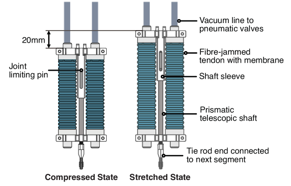
The tendons are mounted to the prismatic joints in pairs, as shown in Fig.4. The pairs of tendons on one side of the joint work antagonistically with the opposite pair, and collectively define the joint stiffness. The knee extensor and knee flexor work antagonistically to impose a stiffness on the knee joint, while ankle dorsiflexor and ankle plantarflexor together impose a stiffness to the ankle joint. Each joint, and hence, each tendon, affects the mechanical impedance on the movement of the leg. Stretching in one tendon will result in compression of the opposite tendon in response to an external force, such as the ground reaction or when the leg collides with an obstacle. The tendons, along with the prismatic joints behave as buffers or passive decoupling mechanisms between the belt transmission and neighbouring sections, such as the femur from the tibia and the foot from the tibia. The tendons provide mechanical damping and compliance, due to their hyperelastic material properties, allowing the foot to passively adapt to an obstacle during collision without resulting in damage to the timing belt or motors. The tendons can then be subsequently stiffened through jamming to improve traction of the leg and generate thrust. When the obstacle or load is removed, the tendons will relax and guide the leg back to its original trajectory. On the other hand, when the leg is air-borne, the prismatic joints are free to move with the linear slides with minimal resistance from the tendons. This is because the tendons are only stretched or compressed when the leg is in contact with the ground or when loaded with an external force (e.g during the stance phase of locomotion). The prismatic joints were also designed to limit the extension of the tendons to 20 mm, to ensure they are within operational loading conditions. A Rocker 500 vacuum pump and pressure regulator were used to jam the tendons. Each tendon mechanism had a separate vacuum line running from the master point to the mounting point on the tendon holder. All tendons were jammed to 50 kPa, as there was little force increase with an increase beyond that pressure.
| Description | Value | Unit | |
| Touchdown Hip Angle | 14 | [∘] | |
| Touchdown Knee Angle | 17.5 | [∘] | |
| Touchdown Ankle Angle | 80 | [∘] | |
| Gravity | 9.8066 | [] | |
| Foot-ground Friction Coefficient | 0.4 | ||
| Knee Extensor Prismatic Joint Displacement | -10 to 10 | [mm] | |
| Knee Flexor Prismatic Joint Displacement | -10 to 10 | [mm] | |
| Ankle Dorsiflexor Prismatic Joint Displacement | -10 to 10 | [mm] | |
| Ankle Plantarflexor Prismatic Joint Displacement | -10 to 10 | [mm] | |
| Knee Extensor Stiffness | = | [N/m] | |
| Knee Flexor Stiffness | = | [N/m] | |
| Ankle Dorsiflexor Stiffness | = | [N/m] | |
| Ankle Plantarflexor Stiffness | = | [N/m] |
II-B Tendon Fabrication and Characterisation
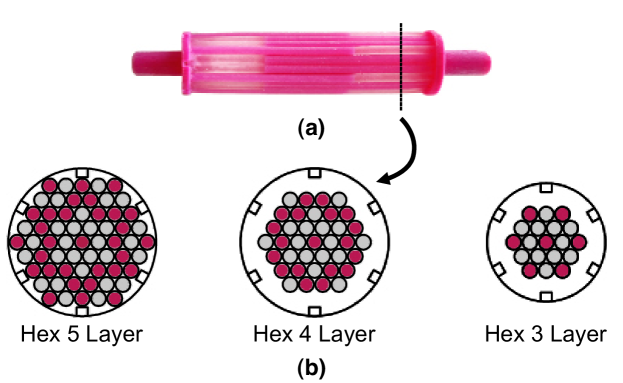
The multi-material fibres were placed in a hexagonal arrangement for higher packing density, as it enabled a greater area of contact between the surface of the fibres and consequently produces a higher jamming force[31]. The tendons were fabricated using a Stratasys Connex3 Objet500 PolyJet 3D printer with a combination of Vero (rigid Shore D) and Agilus30 (flexible Shore A 30) material. By selecting different proportions of these resins as a mixture, materials of various stiffness could be produced. The overall length of the tendons including the end caps is 120 mm, while the fibres are 80 mm length with material distribution ratio of 2/3 Shore A 85 (55 mm) and 1/3 Shore A 30 (30 mm). Tendons of varying number of fibre layers (3,4, and 5) and fibre diameter (1.5 mm, 2.0 mm, 2.5 mm, and 3.0 mm) were produced. The fibres are fixed together at each end in a Fixed-Bundle Type (FBT) configuration with rigid Vero end plates. One end of the end plates was designed with a bore that attaches to a vacuum line, as shown in Fig.4. The use of a multi-material printer is advantageous because these end plates and fibres can be printed as a single object. Hence, no assembly or handling of these intricate fibres were required. A silicone rubber (Smooth-on Ecoflex 00-30) cast concertina membrane was then stretched over the fibre bundle to create an enclosed space for the vacuum. When negative pressure was applied, the membrane forces the fibres together and create a jamming effect.
When the tendons are unjammed, stretching of the tendon results in an initial elongation of the softer sections (Shore A 30). Hence, the tensile stiffness of the fibre was modelled as a pair of springs in series, representing the Shore A 30 and Shore A 85 segments of the fibre. When a vacuum is applied, the interfibre friction forces adjacent fibres to adhere together, resulting in a more evenly distributed deformation along the length of the tendon. Thus, the jammed tendon can be better characterised as a three-series spring, consisting of the middle and two end sections. Details on the analytical and numerical modelling of the tendon are provided[31].
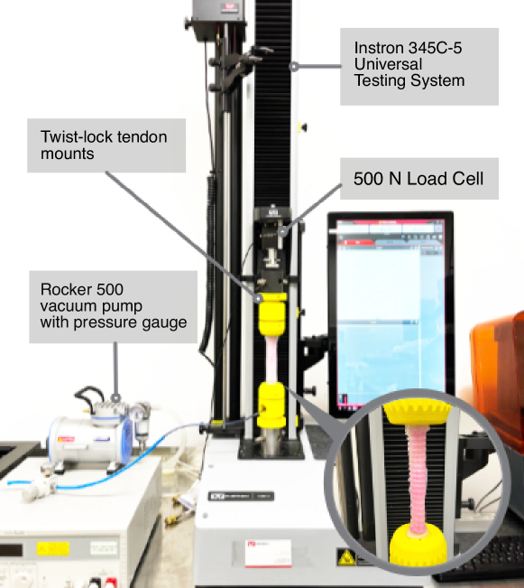
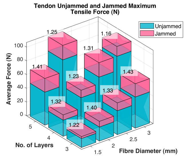
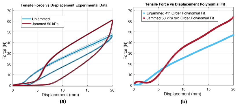
An Instron (Model 34SC-5 Single Column Table) universal testing machine was used to perform the tensile testing for tendons of various fibre diameters and layers. This helps us to tune the morphology of each tendon to its specific use case. For each tendon type, five samples were produced and the unjammed and jammed force-displacement data of these individual samples were collected using the experimental setup in Fig.6. The silicone membranes were used during the entire tensile testing experiments, as our previous work has shown that it does not have an effect towards the measured stiffness [31]. Initially, no vacuum pressure was applied and each sample was stretched up to 20 mm at a rate of 5 mm/s before it was allowed to return to its relaxed state. This step was repeated for 5 cycles. Following this, the vacuum is then turned and a negative pressure of 50 kPA was applied. The same sample was then stretched for another 5 cycles to collect the jammed force-displacement data, as plotted in Fig.8. Results of our tendon characterisation tests for different fibre and layer configurations is shown in Fig.7 and Table.I, which describes the mean maximum unjammed and jammed tensile forces. The stiffness change was calculated using the percentage difference (%) between the jammed and unjammed tensile forces.
III Numerical Model and Design of the Fibre Jammed Leg
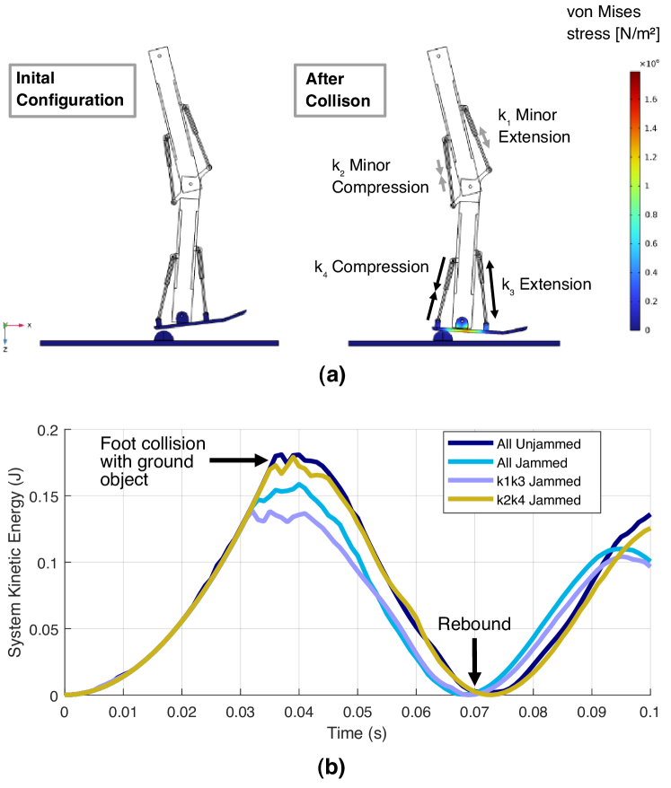
A recent study have found that humans are able to tune the preflex properties, hence, the stiffness of their muscles by either performing eccentric (lengthening) or concentric contraction (shortening) in response to changes in ground conditions [35]. This latent capability of the human musculoskeletal system, could be beneficial in improving the passive adaptation of robotic systems to the environment. The aim of the numerical study is to investigate the effects of jamming different tendons on the dynamic response of the JEG and its ability to absorb impact energy during limb loading. This was done by analysing the change in total kinetic energy of the multibody system when the leg collides with an unexpected obstacle upon touchdown, forcing the tendons to stretch and create a damping moment about the joints. A simplified model of the JEG was designed in CAD and imported into COMSOL Multiphysics to perform a time-dependent multibody dynamics 3D Finite Element Analysis (FEA) simulation, with variables and parameters shown in II. The FEA model’s materials were set based on the JEG prototype, with the femur and tibia modelled as aluminium, the prismatic joints as steel, the plastic foot as ASA, and the ground with the obstacle object as aluminium. To reduce computational expense, only the foot and the ground were modelled as linear elastic, while the rest of the domains were considered rigid with inertial terms considered. The hip, knee, and ankle joints were modelled as 1-DOF revolute joints, as shown in Fig.9. The belt transmission system was simplified to only include the linear slides, which are locked in position to simulate the non-backdrivability of the belt. The tendons and their telescopic shafts were modelled as prismatic joints with a virtual spring elements between their shaft and the sleeve domains. The virtual spring stiffness’ were expressed as force-extension equations, to simulate the hyperelastic behaviour of the tendons, in both their jammed and unjammed states. This was done by utilising real tendon characterisation force-extension data and performing a low-order polynomial regression fitting, as shown in Fig.8. As the tendons only provide a spring force during extension, stiffness was only implemented when there is a positive displacement (extension) of the prismatic joints. When the prismatic joints undergo a negative displacement (compression), the compressive force will cause the fibres to move and rearrange themselves and lead to buckling on the tendon. From the tendon characterisation experiments, the compressive forces produced by the tendons were observed to be significantly lower than their tensile forces (less than 5% for the largest tendon sample, the 3.0mm diameter Hex 4 Layer tendon). Therefore, the stiffness of the tendon during compression could be assumed to be negligible. For ease of reference, the knee extensor was denoted as , the knee flexor as , the ankle dorsiflexor as , and ankle plantarflexor as , as shown in Fig.9.
The obstacle object was modelled as a hemisphere of 40 mm diameter, to create a spherical contact upon collision with the foot. Contact pairs were defined between the bottom surface of the foot and the top surfaces of both the obstacle and ground, with a friction coefficient of 0.4 using the Coulomb friction model. The dynamic penalty method was selected due to its stability and robustness for complex dynamic impact problems. The collision with obstacle object will induce a rotational perturbation on the leg, resulting in the stretch of different tendons depending on the direction (clockwise or anti-clockwise) of rotation. As the JEG is symmetrical about the sagittal plane, we focused mainly on perturbations which resulted in movement of the leg in the anterior-posterior direction. In the simulation, two studies were performed, a (1) toe-down collision, where the obstacle object was located before the ankle and impact would occur around the heel, and a (2) toe-up collision, where contact with the obstacle would occur in front of the foot. As the entire geometry of the leg is symmetrical about the sagittal plane, the centre axis of the hemispherical obstacle was only displaced in the horizontal x-direction. A parametric sweep for each of the two studies were performed, with the stiffness of the prismatic joints set to either the unjammed or jammed stiffness. The change in total kinetic energy of the whole system was measured in the simulation before and after impact with the obstacle object. Total kinetic energy was computed through the integration and summation of kinetic energy densities of the entire physics model. The mesh of the 3D FEA model for the toe-down and toe-up dynamic study consist of 213089 elements and 213313 elements respectively. To improve accuracy of the computed forces, mesh refinement was carried out in the regions where contact occurs, namely the underside of the foot and top of the obstacle object. Each parametric sweep took approximately 150 minutes and computations were carried out using a 3.10GHz Intel Core i9-9960X X-series processor with 64GB RAM.
Upon collision with an object at the heel, the ground reaction force results in an ankle plantarflexion or toe-down motion of the foot, accompanied by a knee flexion, as seen in Fig.10 (a). This results in the extension of the knee extensor and ankle dorsiflexor. Hence by increasing the stiffness of the extending prismatic joints or the tendons in tension, seen in the Jammed configuration, the kinetic energy of the system can be effectively dissipated by 23% upon impact, when compared to the All Unjammed configuration, where all four prismatic joints were set with an unjammed stiffness. Conversely, when only the prismatic joints in compression were stiffened, the Jammed configuration, kinetic energy of the system was found to be the highest upon collision and after rebound of the system. The energy profile was found to be almost identical to the All Unjammed configuration, which indicates that jamming the tendons in compression plays a little to no role in improving the damping ability of the leg. These results show that the jamming of different tendons could affect the energy dissipation of the system, which could be beneficial for disturbance rejection and consequently, improving locomotion stability in complex environments.
| Toe-down Mean Force (SD) [N] | Toe-up Mean Force (SD) [N] | |||||
| 48.7 (0.597) | 11.4 (0.394) | |||||
| 50.0 (1.496) | 19.1 (1.371) | |||||
| 48.8 (0.470) | 16.8 (0.433) | |||||
| 54.1 (0.404) | 21.2 (1.264) | |||||
| 50.1 (0.472) | 29.1 (0.440) | |||||
| 60.4 (0.210) | 18.8 (0.997) | |||||
| 74.8 (0.759) | 16.2 (0.950) | |||||
| 62.0 (1.234) | 29.9 (0.840) | |||||
| 66.6 (2.340) | 22.5 (1.551) | |||||
| 58.0 (2.349) | 29.2 (0.527) | |||||
| 62.0 (1.055) | 32.5 (0.437) | |||||
| 69.7 (1.102) | 25.0 (0.422) | |||||
| 62.7 (0.708) | 32.4 (0.532) | |||||
| 66.3 (0.344) | 32.6 (0.512) | |||||
| 58.9 (2.3076) | 30.2 (0.584) | |||||
| 85.6 (2.270) | 36.4 (0.784) |
*Values highlighted in bold indicate the configuration with the highest mean force for the same number of tendons jammed.
| Unjammed | ||
|
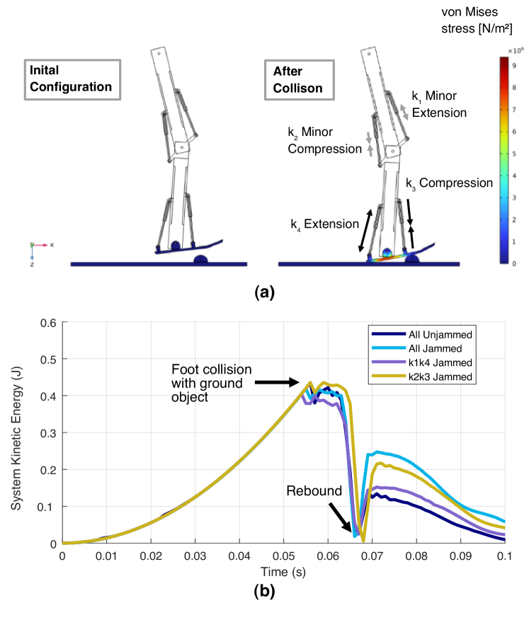
In humans, it is known that the muscle force production, is highly dependent on the instantaneous length of the muscle at which the perturbation is encountered [36]. Hence, the lengthening of the muscles depend on the initial conditions of the limb contact with the ground. In our previous, toe-down collision study, it was observed that the knee extensor and ankle dorsiflexor were the main tendons in extension. However, when the nature of the perturbation or location of the perturbator is changed, the limb and joint dynamics were found to change as well in simulation. When the leg collides with an object in front of the foot, an ankle dorsiflexion or toe-up motion occurs, followed by a knee flexion, as shown in Fig.11. This results in the extension of the knee extensor and ankle plantarflexor. Similarly to the previous study, when these prismatic joints in extension were jammed, the Jammed configuration, the overall kinetic energy of the system upon impact was lowered by 7%, when compared to the All Unjammed configuration. The All Jammed configuration showed the greatest increase in kinetic energy after rebound, and this is followed by Jammed, where only the prismatic joints in compression were jammed. Once again, this result shows that jamming tendons in compression does not further improve the damping ability of the leg and hence, only jamming the tendons in tension should be considered.
Based on the findings of both studies, it becomes evident that employing a fully unjammed or fully jammed leg does not yield improved damping performance. Specifically, during the toe-down collision, the All Unjammed configuration performed the worst, while for a toe-up collision, the All Jammed configuration demonstrated the greatest rebound energy. Hence, it may be summarised that during walking, where loading conditions are continuously changing, an entirely ’soft or entirely stiff leg may not be able to effectively counteract the varying perturbations. Instead, the implementation of directional jamming proves critical in effectively reducing the overall kinetic energy and thus mitigating sudden motions within the perturbed system.
IV JEG Rotational Perturbation Experiment
The role of each tendon pair towards the leg’s perturbation response is difficult to identify at first glance. After a sudden perturbation is encountered, musculoskeletal system is able to automatically perform postural correction responses through preflexes, to keep the body stable and upright. These responses can be adapted to different intensities and types of perturbation to maintain joint stability and prevent falling. However, there is uncertainty in how this behaviour can be transferred into the design of a robotic leg. In this experiment we recreate the occurrence whereby the leg touches down on an obstacle either before or after the ankle, similar to our simulation, to exert opposing reaction moments in the leg. The first experiment is a toe-down rotational perturbation, followed by a toe-up rotational perturbation. In both cases, the JEG’s foot behaves as a lever, with the point of contact with the obstacle or object being the fulcrum. As the leg lowers itself onto the obstacle object, the body weight creates a moment arm about the fulcrum. In order to reduce the joint’s angular acceleration and the kinetic energy of the system as a whole, the fibre jammed tendons must perform work in the form of strain energy and create an ‘effort arm’ in the lever system. Through the contraction of muscles, muscle-tendon complexes in humans function in a similar way, they are able to generate moment arms about the joint to control its motion [37, 38]. The goal of the perturbation experiment is to ascertain and quantify the individual contribution of each tendon pair towards mitigation of a directional perturbation. Furthermore, the experiment aims to validate the outcomes of our simulation.
IV-A Perturbation Experimental Setup
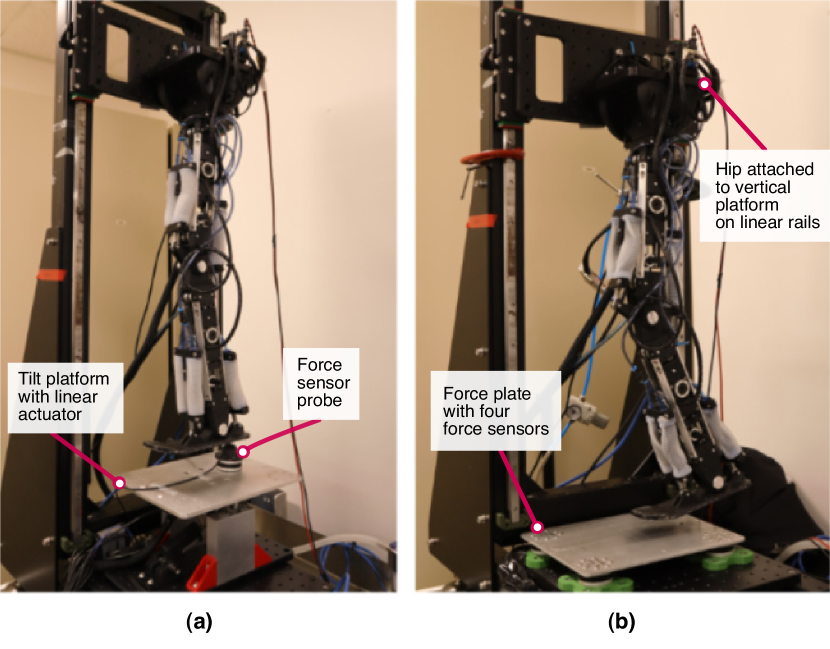
A tilting support surface actuated by a linear actuator with potentiometer feedback (Actuonix Micro Linear Actuator P16-50-64-12-P) was used to create the pitch plane perturbations, as shown in Fig.12. The tilting platform utilises a ’see-saw’ mechanism, in which a rigid aluminium plate rotates about a bearing supported shaft located at the centre. A 3-axis force sensor (OptoForce OMD-45-FH-2000N) with a dome of diameter 30 mm and height 20 mm was mounted on the plate to simulate a point load upon contact with the foot. Measurements obtained from the force sensor will indicate the ’opposing force’ produced by the JEG against the loading dome object, which acts as the perturbator. The dome will ensure that forces are transmitted through the centre of the force sensor. To minimise slip and consequently, the loss of force information due to displacement of the foot, a 3D printed sock of Shore A 60 was used.
The JEG was initially configured to a touchdown or heel-strike pose. The servo motors were left powered on but are unactuated to ensure there was no back-driving belt transmission upon loading of the leg. The same types of tendons were used (2.0 mm fibre diameter 4 Hex layer) for the knee extensors, knee flexors, ankle dorsiflexors, and ankle plantarflexors. The four pairs of tendons were jammed in different configurations, to achieve varying levels of stiffness. As each tendon pair has two states, either (1) unjammed or (2) jammed at 50 kPA, there are hence, possible combinations in the permutation space. For each of the 16 possible permutations, two rotational perturbation experiments were performed and repeated five times, resulting in a total of 160 loading cycles. Between each loading cycle, the vacuum is switched off and atmospheric pressure is allowed to return into the membranes. A waiting period of 5 minutes was allowed to ensure that the tendons return to their original configurations, to avoid bias in the data. The setup of the rotational perturbation experiments are as follows:
-
1.
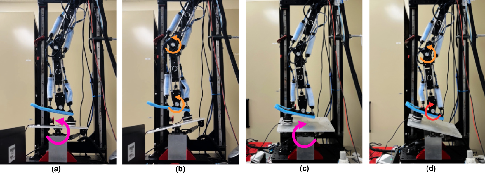
Toe-down Perturbation: The force probe was mounted 60 mm distance from centre of plate before the ankle. The tilting surface rotates in the anti-clockwise direction up to 15∘, resulting in an increasing load applied to the heel, as shown in Fig.13 (a)(b).
-
2.
Toe-up Perturbation: The force probe was mounted 80 mm distance from centre of plate after the ankle. The tilting surface rotates in the clockwise direction up to 15∘, resulting in an increasing load applied to the front of the foot, as shown in Fig.13 (c)(d).
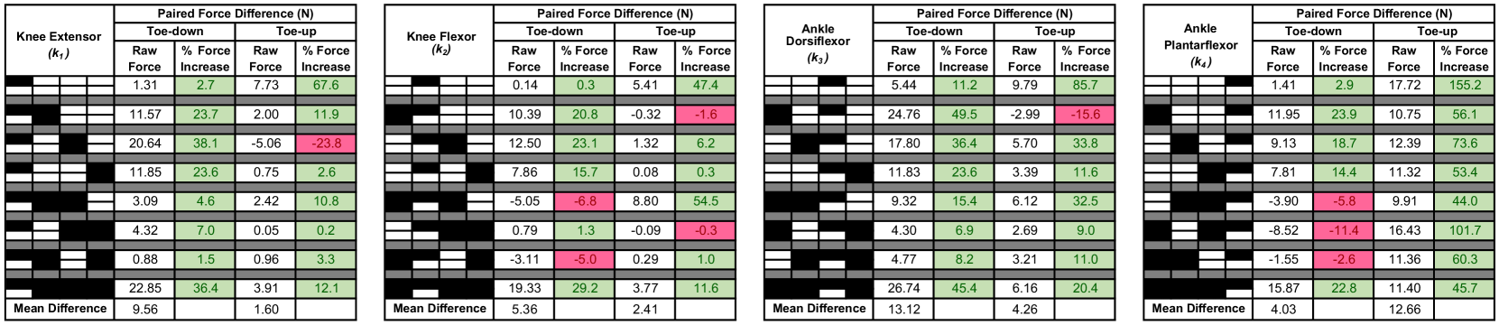
The highest recorded resultant force during leg loading was obtained, and the mean was calculated from the five performed cycles, with results shown in Table.III. In both the toe-down and toe-up experiments, the mean force computed was the lowest when all tendons were unjammed, while it was the highest when all tendons were jammed, as compared to other configurations. However, when considering configurations with only two tendons jammed, it was observed that certain recorded forces exceeded those in which three tendons were jammed. Hence, subsequent analysis of the contribution of each tendon pair towards opposing either a toe-down or toe-up perturbation is required. Hence, individual contributions of the tendons therefore quantified by computing the difference in measured forces between the configuration in which the targeted tendon pair (e.g ) was jammed with the configuration in which the targeted tendon pair was unjammed (e.g vs ). This analysis was performed for each of the targeted tendons and the mean paired difference was computed by summing the individual difference from the eight pairs, and then dividing by eight.
IV-B Perturbation Experimental Results
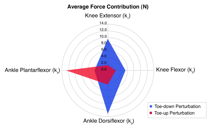
With reference to Fig.14, a positive force contribution is highlighted in green, indicating that jamming the targeted tendon resulted in a higher opposing force, and consequently, a higher damping moment towards the specific directional perturbation. In contrast, a negative contribution is highlighted in red, which indicates there is a loss in measured force when the targeted tendon was jammed. In this case, leaving the targeted tendon unjammed will be more favourable in opposing that directional perturbation. The mean force contribution from each of the tendons is plotted in Fig.15. Results for the toe-down perturbation experiment shows that the ankle dorsiflexor produced the highest contribution, a significant 13.1 N. This is followed by the knee extensor, the knee flexor, and ankle plantarflexor producing a force contributions of 9.56 N, 5.36 N, and 4.03 N respectively. These results can be explained by observing the dynamic response of the leg during the experiment in Fig.13 (a)-(b). Loading on the heel causes the foot to flatten and an ankle plantarflexion to occur. This is followed by flexion of the knee. Hence, the resulting joint rotation of the knee and ankle are in the same direction (anti-clockwise with reference to Fig.12). This causes the the knee extensors and ankle dorsiflexors to stretch, while the knee flexors and ankle plantarflexors compress. By jamming these two tendons, it was observed that the opposing force produced was significantly greater than any other configuration (with exception for the All Jammed configuration), as shown in Table. III. As the tendons produce a tensile force only with extension, and an insignificant compressive force due to buckling, it can be concluded that the damping moments of the joint (knee or ankle) is determined wholly by the tendons which are in tension, which is consistent with what was found from the numerical simulations.
The toe-up perturbation experiment, however, shows opposite results, as the ankle plantarflexor provided the greatest opposing force contribution when loaded with the plate, 12.6 N, followed by the ankle dorsiflexor, 4.26 N. The knee tendons do not show as much contribution in comparison, with the knee extensor and knee flexor contributing forces of 1.60 N and 2.41 N, respectively. This may be due the loading axis being in line with the femur and hence, there was barely any rotational moments about the knee. In this case, the tendon in tension is primarily the ankle plantarflexor, and jamming it will produce the most significant effects to attenuate a toe-up perturbation.
V JEG Walking Experiment
Muscles and tendons perform important roles in not only perturbation rejection, but also in the transmission of forces and support of the body during walking. Walking experiments were conducted to understand the effects of jamming the tendons on the kinematics and dynamics of the leg. By analysing the GRF, the ground-foot interactions and characteristics of the gait, and hence, the efficacy of the variable stiffness capabilities of tendons could be evaluated. The human walking gait cycle consists of two phases: the stance phase, where the foot is in contact with the ground and the swing phase, where the foot is suspended mid-air. The stance phase can be further divided into the touchdown phase, in which the heel strikes the ground, the midstance, in which the foot flattens itself against the ground, and the push-off in which the foot pushes off and accelerates the tibia forward. As the tendons are only engaged when the foot is in contact with the ground, only the stance phase was focused on during the walking experiment. When the leg is airborne and no external forces is applied to the foot, there is little resistance from the tendons acting on the knee and ankle joints. Hence, the torque from the motors is directly utilised to actuate the leg without stretching or compression of the tendons.
V-A Walking Experiment Setup
To evaluate the locomotion performance of the JEG, a custom test rig was fabricated, as in Fig.12 (b). The hip joint servo motor was mounted on a vertical sliding platform to allow changing of the hip height. The platform was fabricated out of rigid plastic with mounting holes and was attached onto the pair of linear motion sliders. As the experimental setup comprises of only a single leg, clamps were used as mechanical limits on the linear rail, under the vertical platform. This is to ensure that the JEG lifts-off the plate during the swing phase, as there is no opposing leg to support its weight. However, during the stance phase, the vertical platform was free to lift from the thrust generated by the JEG. The mass of the JEG along with the vertical plate is 3.65 kg in total.
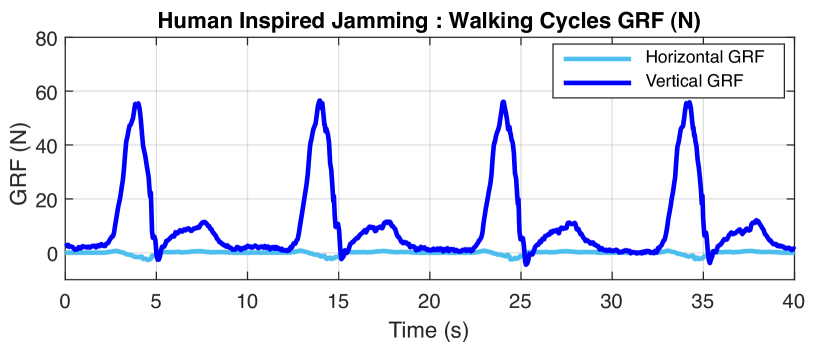
A force platform was developed to measure the vertical and horizontal GRF generated by the JEG during the walking cycle. The force platform is 260 210 mm in length, which consists of a rigid flat aluminium plate with four 3-axis force sensors (OptoForce OMD-45-FH-2000N) mounted under each corner of the plate. The GRF produced by the leg is equal to the sum of the force readings obtained by all four sensors together. The forces produced by the JEG were sampled at 1000 Hz using a DAQ (Optoforce) and were passed through a low-pass Gaussian filter to remove noise. The resultant GRF, was calculated from the , where is the vertical and is the horizontal GRF obtained from the force plate.
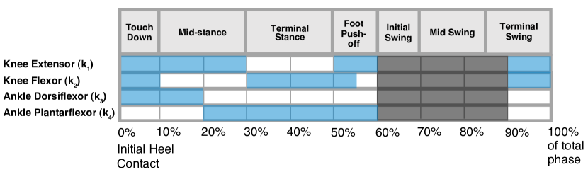
A Bezier curve trajectory was prescribed on the foot and corresponding joint angles was calculated through inverse kinematics. The required servo motor angles for were subsequently obtained by calculating the travel of the belt, for positional control with PID using the Dynamixel SDK in Python. A heel-strike and push-off was implemented in the gait to ensure that the joint moment directions change throughout the gait, to ensure that the antagonistic pair of tendons are utilised. From the prescribed leg trajectory, the time at which the heel-strike, midstance and push-off has occurred was estimated and expressed in percentage gait cycle (%). A PLC controller (CLICK PLC C0-11DD2E-D) controlled the switching of the pneumatic solenoid valves connected to the vacuum to jam and unjam the four tendon pairs. The timing of activation the pneumatic valves were synchronised to relevant parts of the predefined gait cycle. The entire gait cycle duration was set to 10 s and the same gait was used for all experiments. The walking test was performed using 2.0 mm fibre diameter Hex 4 Layer tendons for four different jamming cases:
-
1.
Case I: All tendons unjammed throughout entire gait.
-
2.
Case II: All tendons jammed throughout entire gait.
- 3.
-
4.
Case IV: ‘Two state’ jamming. All tendons were unjammed before touchdown and jammed during midstance just before push-off.
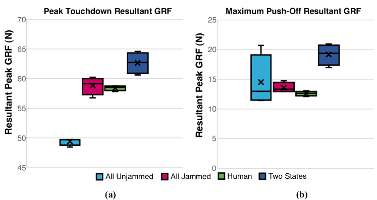
For each case, the walking test was repeated for four cycles to obtain the GRF-time data, as shown in Fig.17. The GRF data was then filtered to remove noise and segmented into individual cycles. The GRF data of each cycle was then averaged to calculate the mean resultant GRF and error bars, indicated by the shaded regions in Fig.18. The peak GRF after touchdown and maximum push-off force was extracted from each cycle, to produce the box-and-whiskers plot presented in Fig.19. For Case I (Fig.18(a)), where there are no observable peaks at push-off, the maximum GRF reading obtained after the 6 s mark was computed.
V-B Walking Experimental Results
The mean resultant GRF obtained from the walking experiments are shown in Fig.18. Similar to the human gait, the maximum peak GRF occurs during the ‘loading response’ phase just after touchdown and before the midstance, where the foot flattens against the ground and accepts the weight of the entire weight of the leg. As predicted, when all tendons are unjammed (Case I) the mean touchdown force (49.4 N) was significantly lower than the rest of the cases. Although the GRF plot showed best damping response, indicated by the gradual rise in force in Fig.18 (a), the overall reduction in stiffness of the leg resulted in unpredictable motions during loading. This is indicated by the lack of a distinct touchdown and push-off peak in the GRF-time plot, which was observed in all other cases. The large variability in measured GRF between cycles was also observed, indicated by the large shaded error region after the 4.5 s mark. During this time, the JEG was performing the push-off phase, and the large variability in measured GRF may be explained by the leg’s inability to support its own weight, resulting in the fluctuating GRF. Furthermore, it was also observed that there was a delayed response in actuation of the leg, leading to varying foot-ground contact times, as indicated by the large shaded error region after the 8 s mark. For some cycles, the contact duration was also found to extend beyond 10s. In all other cases Fig.18(b)(c)(d), the foot loses contact with the ground around consistently, and the resultant GRF immediately goes to zero.
In contrast, when all tendons are jammed (Case II), more distinguished touchdown and push-off peaks were observed (Fig. 18 (b)), with a slightly higher mean resultant forces calculated as 58.8 N and 13.6 N respectively. The human-inspired gait (Case III) produced a closely identical force-profile (Fig.18 (c)), but with a slightly lower mean touchdown and push-off force peaks of similar magnitude, 55.9 N and 12.6 N. However, an important observation to note is that the peak forces obtained for the repeated walking cycles were significantly more consistent compared to other cases, as shown by the shorter box plot in Fig. 19. This is a good indication of repeatability and control of the behaviour of the leg.
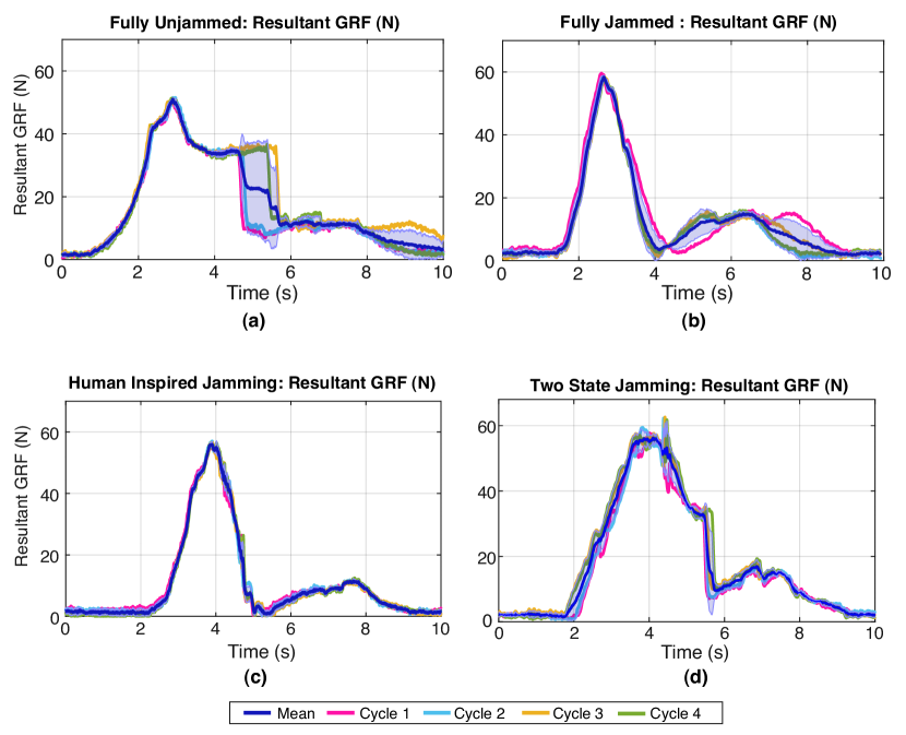
An initial speculation was that the JEG should perform best for Case IV (Fig.18 (d)) when the all the tendons were unjammed during touchdown for maximum impact absorption and later jammed for push-off for maximum thrust. However, results show that although it has a good initial damped response, as indicated by the steady increase in force after touchdown, the magnitude of the touchdown and push-off peak force is the highest compared to the other cases, 62.7 N and 19.2 N respectively. Similar to Case I, the results show no prominent force peaks, resulting in a large variability in both touchdown and push-off forces. The sudden spike in force seen around the 4.3 s mark, was due to the sudden stiffening of the tendons when the vacuum is turned on. Hence, suddenly transitioning from a fully unjammed to a fully jammed state may introduce a jerk or unwanted disturbance, which may affect the stability of the system. With the human-like jamming (Case III), there was almost no observable spikes in force, despite that the pneumatic solenoid valves were rapidly switching on and off to draw air out of the tendons throughout the gait. Hence, a conclusion that can be drawn from this is that a sudden significant change in stiffness of the leg, may be detrimental to the stability of the leg and one of the ways to achieve a gradual increase in stiffness, is to have tendons jammed in alternation.
VI Discussion
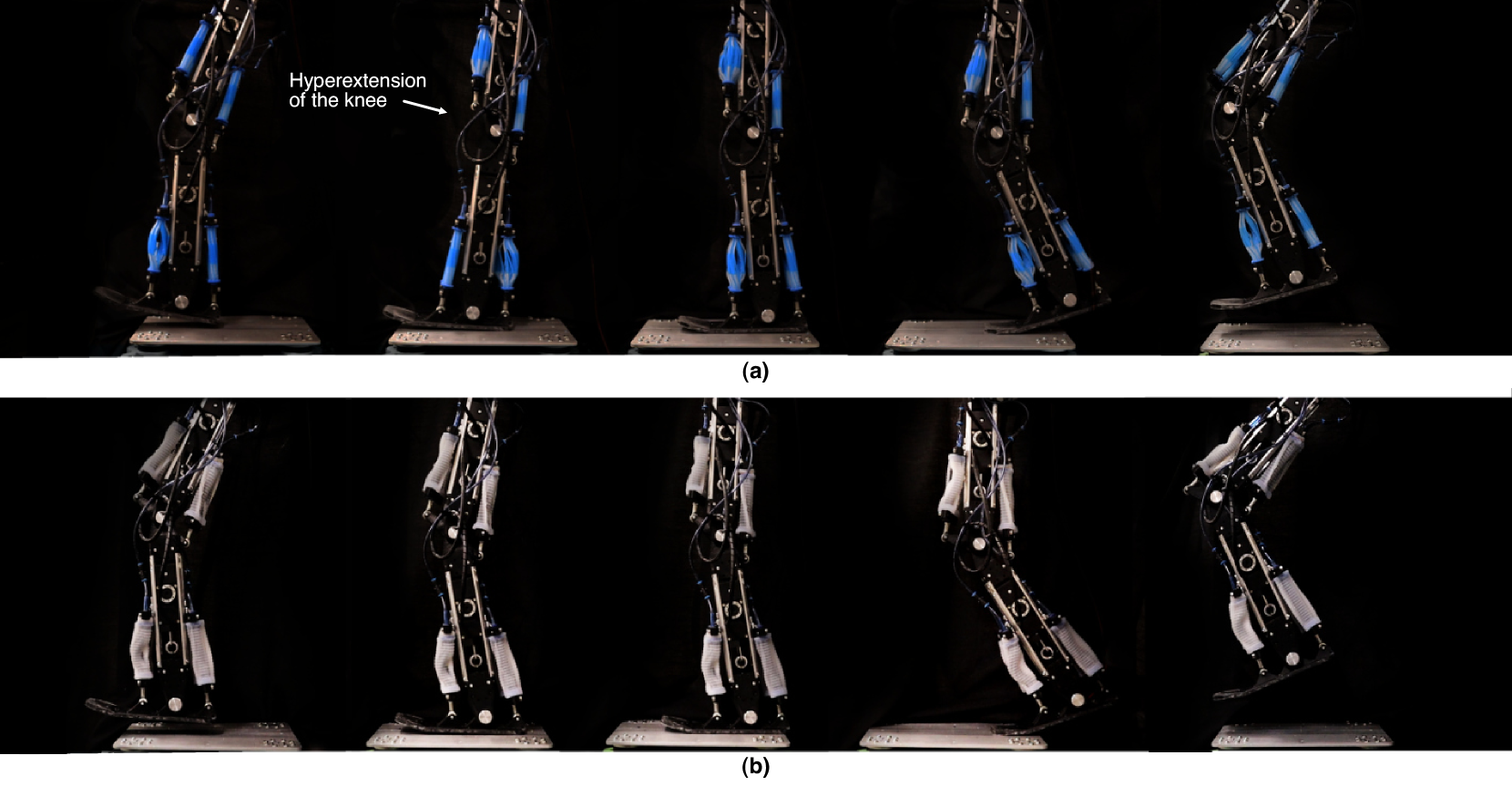
There is a large complexity in understanding the behaviour of soft jammed structures when integrated into robotic legs as the reaction forces acting on the leg are continuously changing. To understand the behaviour of tendons throughout the walking gait, the changing tension and compression of the tendons are studied in Fig.20 (a). The tendon membranes were removed to enable a clear visualisation of the states of the tendons. Based on the perturbation and walking experiments, it is evident that a fully unjammed leg exhibits poor performance under load, resulting in unpredictable and uncontrollable movements. During the midstance, it was observed that the knee joint hyperextends and the entire leg straightens due to insufficient stiffness of the knee, as seen in Fig.20 (a). The whole length of the leg therefore becomes a large moment arm about the hip joint. This results in large undesired torques about the hip joint, and consequently led to the overloading of the motor. This was also seen when the two-state jamming pattern was used, since during the initial touchdown phase, the entire leg was unjammed as well. On the other hand, when the leg was fully jammed or when a human-like jamming pattern was applied, the knee was able to perform forward propulsion of the leg in one smooth motion, as seen in Fig. 20 (b). This shows the critical role of the knee flexor in the transfer of energy between the ankle and hip joint [39]. However, a fully jammed structure or a leg with stiff joints is also not ideal due to higher forces at touchdown, which could potentially lead to damage of the leg or an increased rebound upon ground impact, as observed in our simulations, as shown in Fig.10 and Fig.11.
In the human-inspired jamming pattern, the ankle dorsiflexor were jammed to slow down the heel rocker, in which the ankle performs a plantarflexion moment and the foot flattens against the ground. The ankle dorsiflexor of the JEG was observed to extend the most in comparison to the rest of the tendon pairs during this phase. This behaviour could be compared to the eccentric contraction (lengthening) of the tibialis anterior muscle, which plays an important role to allow for a controlled foot drop. Hence, by jamming the ankle dorsiflexor, we can effectively create a damping moment about the ankle. Upon comparing the results of the perturbation experiments in Fig.15, both ankle tendons were found to be the main contributors towards opposing rotational perturbations. This is consistent with previous findings in biomechanical research, where the ankle muscles were found to be the primary shock absorber and had the highest activation rate when perturbed in the anteroposterior direction [33, 42, 43]. The knee extensor and flexor were also both jammed to increase rigidity of the knee, to slow down the flexion during loading of the leg. Out of the four tendon jamming patterns, the human-inspired jamming (Case III) was found to show a lower magnitude in touchdown GRF compared to when the JEG was fully jammed throughout the entire cycle (Case II) or when jamming was applied after the midstance (Case IV). Results obtained were also more consistent and repeatable compared with the rest of the cases.
VII Conclusion
The study of soft robotics is originally stemmed from the inspiration to mimic the soft and compliant characteristics found in invertebrates. Vertebrates, on the other hand, possess rigid skeletons that are responsible for providing body weight support and facilitate the transmission of forces during movement. In humans, locomotion is only possible through the coordinated action of muscles and tendons, which perform majority of the work. Our research draws inspiration from the concept of preflexes, wherein the inherent mechanical properties of muscles are used to enable automatic stabilisation of movements in response to unexpected perturbations. This remarkable capability of the human musculoskeletal system has motivated our research into developing a biologically inspired articulated soft robotic leg, the JEG, which utilises multi-material fibre jammed tendons as passive compliant mechanisms to act as buffers between the actuators and belt transmission mechanisms from external loads and perturbations. The fibre jammed tendons were placed in an antagonistic configuration on the knee and ankle, allowing variable stiffness tunability for improved versatility and adaptation towards uncertain environments.
The results of our multibody dynamics FEA simulations and physical experiments, indicate that the knee extensors, knee flexors, ankle dorsiflexors and ankle plantarflexor tendons individually play different roles in both stability and locomotion. Depending on the nature of the perturbation, specifically the direction of rotation in which the JEG was loaded, an increase in stiffness on specific tendons could yield vastly different dynamic effects. Our simulations revealed that there was a significant reduction in impact energy absorption of the system to an unexpected collision when only the tendons in tension were jammed, versus when all tendons were fully jammed or fully unjammed, and subsequently leading to a lower energy rebound. To quantify the opposing force contribution of each tendon for rotational perturbations, the JEG was loaded with a force sensor, resulting in toe-down and toe-up motions. We found that the knee extensors and ankle dorsiflexors were the mainly responsible for resisting toe-down perturbations, while the ankle plantarflexors and dorsiflexors performed better for resisting toe-up perturbations. To further understand the role of the knee flexors, which shows little contribution to perturbation resistance, we performed walking experiments and have found that the knee flexors are crucial in maintaining rigidity of the knee during loading, to prevent knee hyperflexion and straightening of the leg, to enable a smooth transition between the midstance to push-off of the leg. By performing a coordinated timed jamming of the tendons, we found that lower foot touchdown forces were observed, along with a more consistent and repeatable gait.
The main implications of our research are as follows: (1) we show the implementation of fibre jammed structures in dynamic load bearing applications, such as legged robotics, (2) we identified the role and contribution of each tendon pairs in providing stability to the leg, and (3) by jamming or increasing the stiffness of certain combination of tendons, we can effectively improve perturbation resistance of the system and walking stability.
This study focuses primarily on the leg’s response towards rotational perturbations. However, it is crucial to acknowledge that perturbations can manifest in many forms, such as translational horizontal perturbations (e.g the sudden stop of a moving bus) or vertical perturbations (e.g missing a step or jumping from an elevated surface). However, given the substantial disparity between these perturbation types, simulating them would require distinct experimental setups. However, there are numerous opportunities in the future to investigate the leg’s response to diverse loading scenarios, to improve our understanding on how soft jammed structures could be effectively implemented in the joints of legged systems.
In biological systems, stability is achieved by the properly tuned material properties of the musculoskeletal system, as well as through neural reflexes and higher brain control. This paper, however, does not address the integration of an active controller to dynamically adjust the stiffness of the tendons. To address this gap in research, a future study may include the implementation robotic vision or sensorising the JEG, and using machine learning techniques to classify the nature of the terrain or footholds before the foot makes impact. A pneumatic controller could then be effectively employed to preemptively jam the tendons in response to predicted perturbations, similarly how humans use visual cues and prior knowledge of the environment to execute anticipatory strategies, and activating their muscles before encountering perturbations.
VIII Acknowledgements
The authors would like to thank Tom Molnar for providing support in the initial development of the walking controller and Sarah Baldwin for help with 3D printing of the tendons.
References
- [1] M. Spenko, S. Buerger, and K. Iagnemma, The DARPA robotics challenge finals: humanoid robots to the rescue. Springer, 2018, vol. 121.
- [2] M. Hutter, C. Gehring, D. Jud, A. Lauber, C. D. Bellicoso, V. Tsounis, J. Hwangbo, K. Bodie, P. Fankhauser, M. Bloesch et al., “Anymal-a highly mobile and dynamic quadrupedal robot,” in 2016 IEEE/RSJ international conference on intelligent robots and systems (IROS). IEEE, 2016, pp. 38–44.
- [3] M. G. Catalano, M. J. Pollayil, G. Grioli, G. Valsecchi, H. Kolvenbach, M. Hutter, A. Bicchi, and M. Garabini, “Adaptive feet for quadrupedal walkers,” IEEE Transactions on Robotics, vol. 38, no. 1, pp. 302–316, 2021.
- [4] G. Loeb, “Control implications of musculoskeletal mechanics,” in Proceedings of 17th international conference of the engineering in medicine and biology society, vol. 2. IEEE, 1995, pp. 1393–1394.
- [5] C. T. Moritz and C. T. Farley, “Passive dynamics change leg mechanics for an unexpected surface during human hopping,” Journal of Applied Physiology, vol. 97, no. 4, pp. 1313–1322, 2004.
- [6] F. Izzi, A. Mo, S. Schmitt, A. Badri-Spröwitz, and D. F. Haeufle, “Muscle prestimulation tunes velocity preflex in simulated perturbed hopping,” Scientific Reports, vol. 13, no. 1, p. 4559, 2023.
- [7] C. Della Santina, M. G. Catalano, A. Bicchi, M. Ang, O. Khatib, and B. Siciliano, “Soft robots,” Encyclopedia of Robotics, vol. 489, 2020.
- [8] B. Kalita, A. Leonessa, and S. K. Dwivedy, “A review on the development of pneumatic artificial muscle actuators: Force model and application,” in Actuators, vol. 11, no. 10. MDPI, 2022, p. 288.
- [9] T. Takuma, S. Hayashi, and K. Hosoda, “3d bipedal robot with tunable leg compliance mechanism for multi-modal locomotion,” in 2008 IEEE/RSJ International Conference on Intelligent Robots and Systems. IEEE, 2008, pp. 1097–1102.
- [10] A. Rosendo, X. Liu, M. Shimizu, and K. Hosoda, “Stretch reflex improves rolling stability during hopping of a decerebrate biped system,” Bioinspiration & biomimetics, vol. 10, no. 1, p. 016008, 2015.
- [11] S. M. Mirvakili, D. Sim, I. W. Hunter, and R. Langer, “Actuation of untethered pneumatic artificial muscles and soft robots using magnetically induced liquid-to-gas phase transitions,” Science Robotics, vol. 5, no. 41, p. eaaz4239, 2020.
- [12] J. Lei, J. Zhu, P. Xie, and M. Tokhi, “Joint variable stiffness of musculoskeletal leg mechanism for quadruped robot,” Advances in Mechanical Engineering, vol. 9, no. 4, p. 1687814017690342, 2017.
- [13] B. Vanderborght, N. G. Tsagarakis, R. Van Ham, I. Thorson, and D. G. Caldwell, “Maccepa 2.0: compliant actuator used for energy efficient hopping robot chobino1d,” Autonomous Robots, vol. 31, no. 1, pp. 55–65, 2011.
- [14] F. Guenther, H. Q. Vu, and F. Iida, “Improving legged robot hopping by using coupling-based series elastic actuation,” IEEE/ASME Transactions on Mechatronics, vol. 24, no. 2, pp. 413–423, 2019.
- [15] D. Fedorov and L. Birglen, “Design of a self-adaptive robotic leg using a triggered compliant element,” IEEE Robotics and Automation Letters, vol. 2, no. 3, pp. 1444–1451, 2017.
- [16] R. Sato, E. Kazama, A. Ming, M. Shimojo, F. Meng, H. Liu, X. Fan, X. Chen, Z. Yu, and Q. Huang, “Design and control of robot legs with bi-articular muscle-tendon complex,” in 2017 IEEE international conference on robotics and biomimetics (ROBIO). IEEE, 2017, pp. 2605–2610.
- [17] S.-A. Abad, N. Herzig, S. M. H. Sadati, and T. Nanayakkara, “Significance of the compliance of the joints on the dynamic slip resistance of a bioinspired hoof,” IEEE Transactions on Robotics, vol. 35, no. 6, pp. 1450–1463, 2019.
- [18] K. Radkhah, C. Maufroy, M. Maus, D. Scholz, A. Seyfarth, and O. Von Stryk, “Concept and design of the biobiped1 robot for human-like walking and running,” International Journal of Humanoid Robotics, vol. 8, no. 03, pp. 439–458, 2011.
- [19] S. G. Fitzgerald, G. W. Delaney, and D. Howard, “A review of jamming actuation in soft robotics,” in Actuators, vol. 9, no. 4. MDPI, 2020, p. 104.
- [20] M. Manti, V. Cacucciolo, and M. Cianchetti, “Stiffening in soft robotics: A review of the state of the art,” IEEE Robotics & Automation Magazine, vol. 23, no. 3, pp. 93–106, 2016.
- [21] M. Shen, A. B. Clark, and N. Rojas, “A scalable variable stiffness revolute joint based on layer jamming for robotic exoskeletons,” in Towards Autonomous Robotic Systems: 21st Annual Conference, TAROS 2020, Nottingham, UK, September 16, 2020, Proceedings 21. Springer, 2020, pp. 3–14.
- [22] C. Sozer, L. Paternò, G. Tortora, and A. Menciassi, “A novel pressure-controlled revolute joint with variable stiffness,” Soft Robotics, vol. 9, no. 4, pp. 723–733, 2022.
- [23] E. Lathrop, I. Adibnazari, N. Gravish, and M. T. Tolley, “Shear strengthened granular jamming feet for improved performance over natural terrain,” in 2020 3rd IEEE International Conference on Soft Robotics (RoboSoft). IEEE, 2020, pp. 388–393.
- [24] S. Hauser, P. Eckert, A. Tuleu, and A. Ijspeert, “Friction and damping of a compliant foot based on granular jamming for legged robots,” in 2016 6th IEEE international conference on biomedical robotics and biomechatronics (BioRob). Ieee, 2016, pp. 1160–1165.
- [25] S. Chopra, M. T. Tolley, and N. Gravish, “Granular jamming feet enable improved foot-ground interactions for robot mobility on deformable ground,” IEEE Robotics and Automation Letters, vol. 5, no. 3, pp. 3975–3981, 2020.
- [26] B. Yang, R. Baines, D. Shah, S. Patiballa, E. Thomas, M. Venkadesan, and R. Kramer-Bottiglio, “Reprogrammable soft actuation and shape-shifting via tensile jamming,” Science Advances, vol. 7, no. 40, p. eabh2073, 2021.
- [27] M. Brancadoro, M. Manti, S. Tognarelli, and M. Cianchetti, “Preliminary experimental study on variable stiffness structures based on fiber jamming for soft robots,” in 2018 IEEE International Conference on Soft Robotics (RoboSoft). IEEE, 2018, pp. 258–263.
- [28] B. Aktaş, Y. S. Narang, N. Vasios, K. Bertoldi, and R. D. Howe, “A modeling framework for jamming structures,” Advanced Functional Materials, vol. 31, no. 16, p. 2007554, 2021.
- [29] S. Jadhav, M. R. A. Majit, B. Shih, J. P. Schulze, and M. T. Tolley, “Variable stiffness devices using fiber jamming for application in soft robotics and wearable haptics,” Soft Robotics, vol. 9, no. 1, pp. 173–186, 2022.
- [30] L. Arleo, L. Lorenzon, and M. Cianchetti, “Variable stiffness linear actuator based on differential drive fiber jamming,” IEEE Transactions on Robotics, 2023.
- [31] J. Pinskier, J. Brett, L. Hanson, K. L. Surdo, and D. Howard, “Jammkle: Fibre jamming 3d printed multi-material tendons and their application in a robotic ankle,” in 2022 IEEE/RSJ International Conference on Intelligent Robots and Systems (IROS). IEEE, 2022, pp. 8507–8514.
- [32] G. D. Howard, J. Brett, J. O’Connor, J. Letchford, and G. W. Delaney, “One-shot 3d-printed multimaterial soft robotic jamming grippers,” Soft Robotics, vol. 9, no. 3, pp. 497–508, 2022.
- [33] K.-H. Shen, S. K. Prajapati, J. Borrelli, V. L. Gray, K. P. Westlake, M. W. Rogers, and H.-Y. Hsiao, “Neuromechanical control of impact absorption during induced lower limb loading in individuals post-stroke,” Scientific reports, vol. 12, no. 1, p. 19104, 2022.
- [34] T. R. Derrick, J. Hamill, and G. E. Caldwell, “Energy absorption of impacts during running at various stride lengths.” Medicine and science in sports and exercise, vol. 30, no. 1, pp. 128–135, 1998.
- [35] M. Araz, S. Weidner, F. Izzi, A. Badri-Spröwitz, T. Siebert, and D. F. Haeufle, “Muscle preflex response to perturbations in locomotion: In vitro experiments and simulations with realistic boundary conditions,” Frontiers in Bioengineering and Biotechnology, vol. 11, p. 1150170, 2023.
- [36] A. A. Biewener and M. A. Daley, “Unsteady locomotion: integrating muscle function with whole body dynamics and neuromuscular control,” Journal of Experimental Biology, vol. 210, no. 17, pp. 2949–2960, 2007.
- [37] C. N. Maganaris, “In vivo measurement-based estimations of the moment arm in the human tibialis anterior muscle-tendon unit,” Journal of Biomechanics, vol. 33, no. 3, pp. 375–379, 2000.
- [38] J. R. Baxter and S. J. Piazza, “Plantar flexor moment arm and muscle volume predict torque-generating capacity in young men,” Journal of applied physiology, vol. 116, no. 5, pp. 538–544, 2014.
- [39] D. Torricelli, J. Gonzalez, M. Weckx, R. Jiménez-Fabián, B. Vanderborght, M. Sartori, S. Dosen, D. Farina, D. Lefeber, and J. L. Pons, “Human-like compliant locomotion: state of the art of robotic implementations,” Bioinspiration & biomimetics, vol. 11, no. 5, p. 051002, 2016.
- [40] D. A. Winter, Biomechanics and motor control of human gait: normal, elderly and pathological, 1991.
- [41] A. Silder, S. L. Delp, and T. Besier, “Men and women adopt similar walking mechanics and muscle activation patterns during load carriage,” Journal of biomechanics, vol. 46, no. 14, pp. 2522–2528, 2013.
- [42] K. E. Zelik and A. D. Kuo, “Mechanical work as an indirect measure of subjective costs influencing human movement,” PloS one, vol. 7, no. 2, p. e31143, 2012.
- [43] R. T.-L. Zhu, P.-Z. Lyu, S. Li, C. Y. Tong, Y. T. Ling, and C. Z.-H. Ma, “How does lower limb respond to unexpected balance perturbations? new insights from synchronized human kinetics, kinematics, muscle electromyography (emg) and mechanomyography (mmg) data,” Biosensors, vol. 12, no. 6, p. 430, 2022.
![[Uncaptioned image]](/html/2308.01758/assets/x21.png) |
Lois Liow is a Robotics Engineer at CSIRO Data61. She graduated from Imperial College London in Design Engineering with an integrated Masters of Engineering (MEng) in 2019. During her time at Imperial College London, she conducted research in robotic manipulation and in the design of underactuated tendon-driven robotic hands. Since joining CSIRO, she has been providing engineering support to the team and has also been performing research in articulated soft robotic systems, as well as space manipulation technologies. |
![[Uncaptioned image]](/html/2308.01758/assets/x22.png) |
James Brett is a Senior Mechatronic Engineer who graduated Griffith University in 2014. After graduating, he began work as a Design Engineer within the Industrial Automation and Robotics field. James commenced work with CSIRO in 2016 and he currently works as a Mechatronics Engineer in the Robotics and Autonomous Systems Group at CSIRO Data61. |
![[Uncaptioned image]](/html/2308.01758/assets/x23.png) |
Joshua Pinskier is a Postdoctoral Research Fellow at CSIRO Data61. He completed dual bachelors in Mechatronics Engineering and Commerce at Monash University in 2015, before completing his PhD in Mechanical Engineering at Monash in 2019. His PhD research into design optimisation of compliant mechanisms for haptic-guided nanomanipulation received multiple awards including Best Paper at 3M-Nano 2015. His current research explores topology optimisation methods to explore complex design spaces and generate high performing soft robotic components. |
![[Uncaptioned image]](/html/2308.01758/assets/x24.png) |
Lauren Hanson Lauren is a Senior Mechanical Engineer in the Robotics and Autonomous Systems Group at CSIRO. She studied a dual degree of Mechanical Engineering (Honours) and Science at Monash University. Since joining CSIRO she has worked on multiple robotics projects, including leading development of mechanical systems for the CSIRO Data61 DARPA Subterranean Challenge team and being an active member of the soft robotics research team. She is currently supporting the CSIRO space research efforts, and is designing hardware for a research payload to be launched to the ISS later this year. |
![[Uncaptioned image]](/html/2308.01758/assets/x25.png) |
Louis Tidswell started with CSIRO in November 2021 to complete his engineering internship with Data61. He then completed his Mechatronics Engineering honours project with CSIRO and Queensland University of Technology during 2022 in the field of soft robotics. After graduating, he accepted a job as a graduate Mechatronics Engineer with Athena Artificial Intelligence. |
![[Uncaptioned image]](/html/2308.01758/assets/x26.png) |
Navinda Kottege (M’05-SM’14) received his BSc in Engineering Physics (University of Colombo) in 2003 and his PhD in Engineering (ANU) in 2009. He is the Research Director responsible for Robotics, Computer Vision and Distributed Sensing at CSIRO’s Data61. Navinda initiated and led legged robot research within CSIRO since 2011, with a focus on navigation in unstructured environments. Navinda is a senior member of the IEEE, and a former Chair of the IEEE Queensland joint chapter for Control Systems/Robotics and Automation Societies. He is an Adjunct Associate Professor at both Queensland University of Technology and University of Queensland. |
![[Uncaptioned image]](/html/2308.01758/assets/x27.png) |
David Howard David is a Principal Research Scientist and Soft Robotics Research Leader at CSIRO, Australia’s national science body. He received his BSc in Computing from the University of Leeds in 2005, and the MSc in Cognitive Systems at the same institution in 2006. In 2011 he received his PhD from the University of the West of England. He is a member of the IEEE and ACM, and an avid proponent of education, STEM, and outreach activities. His work has been published in IEEE and Nature journals. His interests include nature-inspired algorithms, learning, soft robotics, the reality gap, and evolution of form. |