Near-Field Communications: A Degree-of-Freedom Perspective
Abstract
Multiple-antenna technologies are advancing towards large-scale aperture sizes and extremely high frequencies, leading to the emergence of near-field communications (NFC) in future wireless systems. To this context, we investigate the degree of freedom (DoF) in near-field multiple-input multiple-output (MIMO) systems. We consider both spatially discrete (SPD) antennas and continuous aperture (CAP) antennas. Additionally, we explore three important DoF-related performance metrics and examine their relationships with the classic DoF. Numerical results demonstrate the benefits of NFC over far-field communications (FFC) in terms of providing increased spatial DoFs. We also identify promising research directions for NFC from a DoF perspective.
I Introduction
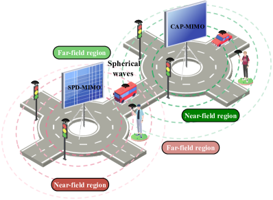
The electromagnetic (EM) radiation field emitted by antennas is divided into two regions: the far-field and the radiation near-field. The Rayleigh distance, determined by the product of the array aperture’s square and the carrier frequency, serves as the boundary between these regions [1]. In the far-field region, beyond the Rayleigh distance, EM waves exhibit different propagation characteristics compared to the near-field region within it. Planar waves effectively approximate the far-field EM field, while the near-field EM field requires precise modeling using spherical waves [1].
Limited by the size of antenna arrays and the operating frequency bands, the Rayleigh distance in current cellular systems typically spans only a few meters, making the near-field effects negligible. Thus, existing cellular communications predominantly rely on theories and techniques from far-field communications (FFC). However, with the rapid advances of wireless technology, next-generation wireless communications rely on extremely large-scale antenna arrays and higher frequencies to cater for the ever-increasing thirst for communication services [2]. In these advanced scenarios, near-field communications (NFC) can extend over longer distances, surpassing the conventional proximity range. The deployment of massive antenna arrays and the utilization of high-frequency bands allow NFC to be effective at distances of hundreds of meters, thereby opening up novel opportunities for the development of NFC theories and techniques [1, 2].
In the realm of wireless communications, the degree of freedom (DoF) concept has emerged as a crucial framework for understanding the capabilities and potential of different communication systems [3]. Briefly, the DoF provides insights into the number of independent signal dimensions that can be exploited for conveying information in a wireless channel. While traditional FFC have been extensively studied within this context, the unique physical properties of NFC exhibit distinct characteristics that necessitate a fresh exploration of DoF.
The adoption of a DoF perspective in NFC is motivated by several factors. Firstly, NFC offers increased DoFs, which represents a significant advantage over FFC. By understanding the DoF characteristics of NFC systems, we can unveil the superior data capacity and transmission capabilities of NFC compared to FFC. Secondly, characterizing the DoF in NFC assists in optimizing the system parameters, such as the antenna configurations and transmission strategies, leading to improved overall performance. Thirdly, adopting a DoF perspective facilitates the development of communication protocols and algorithms specifically tailored for NFC environments, resulting in enhanced reliability, coverage, and throughput. Although there are some studies analyzing NFC’s DoF [1], this field is still in its infancy.
Hence, we aim for the critical appraisal of NFC and its DoF. Our focus is on point-to-point multiple-input multiple-output (MIMO) channels under line-of-sight (LoS) propagation, as illustrated in Figure 1. This emphasis arises from the anticipation that future NFC will operate at high frequencies, leading to a prevalence of LoS communication associated with limited multi-path effects. We commence by exploring the DoFs achieved in near-field MIMO by spatially discrete antennas (SPD-MIMO). Subsequently, we extend our analysis to the near-field MIMO supported by continuous aperture antennas (CAP-MIMO). Utilizing numerical simulations, we demonstrate the superiority of NFC over FFC concerning its DoF and establish connections between the DoF and effective DoF (EDoF). Finally, future research ideas are discussed.
II DoFs Achieved in SPD-MIMO
In practical implementations of NFC, a viable approach is to equip the transceiver with an extensive antenna array comprising a large number of SPD patch antennas. In this section, we will delve into a comprehensive analysis of the achievable DoFs in near-field SPD-MIMO.
II-A Calculation of the DoF
II-A1
In the context of SPD-MIMO, the overall channel response can be represented as a matrix having dimensions of , where denotes the number of receive antennas and represents the number of transmit antennas. By applying the singular value decomposition (SVD) to this channel matrix, the SPD-MIMO channel can be effectively decomposed into multiple independent single-input single-output (SISO) sub-channels that operate in parallel without mutual interference. Mathematically, the number of positive singular values or the rank of the correlation matrix corresponds to the number of sub-channels having a non-zero signal-to-noise ratio (SNR). Each of these sub-channels accommodates an independent communication mode within the MIMO channel. The total number of communication modes is referred to as the spatial DoF of the channel, denoted as . On the other hand, for a MIMO Gaussian channel, the capacity growth rate can be shown to be at high SNR. Therefore, the DoF is also termed as the high-SNR slope or maximum multiplexing gain (relative to a SISO channel) [1].
Given a channel matrix , the spatial DoFs are inherently limited and cannot exceed the minimum value between and . In a far-field MIMO LoS channel, only a single incident angle is available due to the almost parallel planar-wave propagation. Consequently, the channel matrix is of rank-, resulting in a very limited DoF, namely . By contrast, within the near-field region, the spherical waves exhibit different phase-shifts and power levels for each link. This diversity leads to a higher rank for the MIMO channel matrix and subsequently a higher DoF compared to the far-field scenario. Notably, if the SPD antennas are well separated, the achievable DoFs for the near-field MIMO LoS channel can approach the minimum value between and . This signifies that spatial multiplexing can be supported even in the absence of a rich scattering environment, which is a significant advantage of NFC.
II-A2
The aforementioned arguments suggest that employing a high number of antennas constitutes an effective technique of increasing the DoFs in NFC. By reducing the antenna spacing within a fixed aperture size, the number of spatial DoFs can be expanded. It is worth noting that when two antennas are in each other’s close proximity, the waves they generate at the receiver antenna array become nearly identical. Consequently, these two antennas become indistinguishable at the receiver. This limitation should be considered as it could restrict the potential increase in channel capacity, when a large number of transceiving antennas are incorporated into a fixed aperture. This limitation has been theoretically demonstrated in [4, 5].
To augment our exposition, we represent the ordered positive singular values of matrix as . Miller [4] demonstrated by employing prolate spheroidal wave functions that for small values of , the values fall off slowly until they reach a critical threshold, beyond which they decay rapidly. This critical threshold is termed as the “effective degree of freedom (EDoF)”, denoted as . Moreover, this phenomenon becomes more prominent as the number of transceiving antennas increases. These findings indicate that although harnessing more antennas can lead to an increased number of independent sub-channels, only the dominant ones can be effectively utilized for supporting reliable communications.
Furthermore, for a large number of antennas, Miller [4] concludes that the upper limit of is proportional to the product of transmitter and receiver areas and it is inversely proportional to the link distance. These findings are derived using the uniform spherical wave (USW) model described in [1, Eqn. (35)]. The USW model is applicable in the near-field region, where the communication distance exceeds the uniform-power distance, exhibiting uniform channel gains and non-linear phase-shifts. However, it is important to note that as the link distance becomes comparable to the transceiver sizes (i.e., NFC within the uniform-power distance), the accuracy of the USW model and the EDoF derived in [4] diminishes. To address this, Dardari introduced a more general formula for based on 2D sampling theory arguments for the non-uniform spherical wave (NUSW) model of [5]. Although this formula may present tractability challenges, again, it reveals that the upper limit of is proportional to the product of the transmitter and receiver areas, while it is inversely proportional to the link distance. These improvements enhance our understanding of EDoF in NFC systems.
In summary, the conclusions drawn from [4] and [5] suggest that the number of dominant communication modes and channel capacity can be enhanced in two primary means: increasing the aperture size and reducing the communication distance. Remarkably, these strategies align with the commonly employed techniques for supporting NFC, emphasizing the superior spatial EDoF capabilities of NFC systems.
II-B Exploitation of the DoF
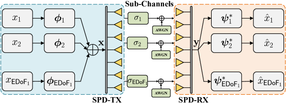
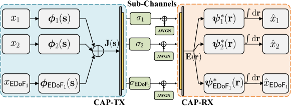
To fully utilize the increased DoFs or EDoFs (i.e., ) offered by near-field SPD-MIMO, it is crucial to apply SVD to the channel matrix . This allows for the identification of the right and left singular vectors corresponding to the dominant singular values. To further optimize the achievable channel capacity, the water-filling algorithm can be utilized for judiciously sharing the power among the parallel sub-channels. Figure 2(a) illustrates the detailed architecture that outlines the exploitation of DoF in NFC relying on SPD antennas.
| Metric | Degree of Freedom: DoF | Effective Degree of Freedom: EDoF | |||||||||||||
|---|---|---|---|---|---|---|---|---|---|---|---|---|---|---|---|
| Definition | [3] | [4] | [9] | [11] | |||||||||||
| Values Range | , | , | , | , | |||||||||||
| SNR Ranges | High-SNR region | Low&Medium-SNR region | Low-SNR region | All SNR ranges | |||||||||||
|
|
|
|
|
|||||||||||
| SPD-MIMO Fae-Field (Calculation) | LoS | ||||||||||||||
| NLoS | Rank of , | Obtained from SVD of , | [9], | [11], | |||||||||||
| Upper bound: | Upper bound: | Upper bound: | Upper bound: | ||||||||||||
| SPD-MIMO Near-Field (Calculation) | LoS | Rank of , | Obtained from SVD of , | , [8, Eqn. (8)], | , | ||||||||||
| Upper bound: | Upper limit: , , [4, 5] | Upper limit: [8, Eqn. (18)], | Upper bound: | ||||||||||||
| NLoS | Rank of , | Obtained from SVD of , | , | , | |||||||||||
| Upper bound: | Upper limit: , [6, 7] | Upper bound: | Upper bound: | ||||||||||||
-
*
is the effective aperture size of the transmitter/receiver
-
**
is the minimum value between and
-
***
is the link distance between the transmitter and receiver
II-C Discussion and Outlook
II-C1 MIMO NLoS Channel
The DoF of MIMO NLoS channels is influenced by the geometrical distribution of scatterers. In a rich scattering environment, the MIMO channel can achieve full rank for both the near-field and far-field regions due to the random phase shifts introduced by scatterers. As a result, the achievable DoFs in MIMO LoS channels may approach the minimum value between the numbers of receive and transmit antennas. When a large number of transceiving antennas are employed, the authors of [6] and [7] have demonstrated by leveraging sampling theory that the upper limit of is directly proportional to the effective aperture of the transceivers.
For SPD-MIMO, the exact values of and can be obtained from the SVD of the channel matrix for both LoS and NLoS channels. However, obtaining tractable closed-form expressions for these two performance metrics remains challenging. To address this, previous studies have investigated the upper limit of under various channel conditions by considering the asymptotic scenario of a large number of transceiving antennas [5, 7, 6, 4]. These elegant expressions are derived using Green’s function model, which may appear impervious to newcomers, who are experts in other fields. This leads to an important question: Can there be DoF-related metrics that evaluate NFC performance in a non-asymptotic manner in closed form? The answer is affirmative, and the following parts provide the details of these metrics.
II-C2
Recently, some researchers have introduced an alternative metric to assess NFC performance, also termed as the “effective degree of freedom (EDoF)”, which is given by and denoted as . can be readily calculated for any arbitrary channel matrix, regardless of whether the system operates in near- or far-field regions, and under LoS or NLoS propagations. As an example, let us consider the LoS channel. In far-field LoS MIMO, the channel matrix has a rank of , and hence becomes . Conversely, for near-field LoS MIMO, falls between and , and it is also proportional to the number of transceiving antennas [8]. The upper limit of is obtained for near-field LoS MIMO by letting the number of antennas approach infinity, demonstrating its inverse proportionality to the link distance. The results in [8] indicate that the near-field effect can enhance . Several studies have claimed, without any justifications, that represents the equivalent number of sub-channels, as depicted in Figure 2(a), and can be employed for evaluating the NFC performance [8]. However, it is crucial to note that these statements lack mathematical rigor and may lead to misinterpretations of the actual meaning and implications of .
The concept of was originally introduced by Muharemovic et al. [9], who built upon Verdú’s previous work [10] to approximate the MIMO channel capacity as in the low-SNR regime. Here, represents the bit energy over noise power spectral density, and is the minimum value required for reliable communications. Additionally, is determined by the product of the channel capacity and the SNR [10, Eqn. (14)]. By considering the insights gleaned from [9] and [10], it becomes evident that possesses a distinct physical interpretation when compared to and . Generally, the value of is not directly associated with the number of dominant sub-channels depicted in Figure 2(a). However, an exception occurs when the dominant sub-channels have nearly identical channel gains, i.e., . In such cases, can be approximately represented by the value of . Our numerical results in Section IV suggest that this scenario can happen in certain LoS channels. Nonetheless, this approximation remains heuristic, and its generality lacks mathematical rigor.
To summarize, serves as a significant performance metric for NFC in the low-SNR region, yet it cannot be simply interpreted as the equivalent number of sub-channels. Its significance and interpretation are different from those of and . Hence, it is important to discern its distinct role in NFC.
II-C3
To fully harness the spatial DoFs offered by NFC MIMO, it is desirable to operate the system in the high-SNR region. In such scenarios, the channel capacity should exhibit roughly linear growth vs. the or , given a fixed transmit power. However, achieving this high SNR condition may not always be feasible in practical settings. In recognition of this fact, Shiu et al. [11] introduced an alternative metric, also termed as the “effective degree of freedom (EDoF)”, which represents the number of equivalent sub-channels actively participating in conveying information under specific operating conditions. For clarity, we refer to this metric as .
In a SISO channel, a -fold increase in transmit power leads to a capacity increase of bps/Hz at high SNRs. If a system is equivalent to SISO channels in parallel, the overall system capacity should increase by bps/Hz when the transmit power is multiplied by a factor of . To formally define , Shiu et al. [11] express it as , where represents the MIMO channel capacity at a given SNR. It is important to note that can refer to the instantaneous capacity, outage capacity, or ergodic capacity, making the expression of applicable to arbitrary channel matrices, regardless of whether the system operates in the near- or far-field regions, and under LoS or NLoS propagations. Let us consider the LoS channel as an example. In far-field LoS MIMO, the channel matrix has a rank of , leading to being no larger than . Conversely, for near-field LoS MIMO, could exceed [11]. Observe from this comparison that the near-field effect can improve .
Essentially, describes the number of equivalent SISO sub-channels at a given SNR, making it a valuable performance indicator for NFC in different SNR scenarios.
II-C4 Summary and Outlook
A detailed comparison among , , , and is summarized in Table I. Taken together, these four DoF-related metrics possess different physical meanings and scopes of application. As such, they should be appropriately utilized based on the practical demands of NFC. While the existing results have been primarily focused on , it is crucial to develop a comprehensive mathematical framework for calculating the upper limits of and under both LoS and NLoS scenarios. This avenue represents a potential direction for future research.
III DoFs Achieved in CAP-MIMO
Utilizing CAP antennas presents a promising technique of improving the performance of MIMO systems having limited apertures. In contrast to SPD-MIMOs, which involve a large number of discrete antennas having specific spacing, CAP-MIMO adopts an infinite number of antennas with infinitesimal spacing. This section investigates the spatial DoFs in near-field CAP-MIMO.
III-A Calculation of the DoF
We consider a scenario where both the transmitter and receiver are equipped with CAP antennas, which is analogous to the MIMO setup for SPD antennas. However, in contrast to the SPD antenna array that delivers finite-dimensional signal vectors, the CAP surface supports a continuous distribution of source currents within the transmitting aperture, giving rise to the generation of an electric radiation field at the receiver aperture. The spatial channel impulse response between any two points on the transceiving surfaces is described by Green’s function, which connects the transmitter’s current distribution and the receiver’s electric field via a spatial integral. Green’s function accurately models the EM characteristics in free space and effectively represents the channel response between the transceivers, akin to the channel matrix for SPD-MIMOs.
III-A1
Based on the above considerations, the spatial CAP-MIMO channel can be decomposed into a series of parallel SISO sub-channels by finding the equivalent “SVD” of Green’s function [4, Eqn. (27)]. The resultant equivalent “left singular vectors” and “right singular vectors” form two complete sets of orthogonal basis functions, one for the transmitter’s aperture and the other for the receiver’s aperture. The resultant equivalent “singular values” correspond to the channel gains of the decomposed sub-channels. Alternatively, these “singular values” can be obtained through the eigenvalue decomposition of the Hermitian kernel of Green’s function (analogous to the correlation matrix for SPD antennas); see [4, Eqn. (42)] and [1, Section II-C] for more details. The number of non-zero “singular values” of Green’s function, or equivalently, the non-zero eigenvalues of its kernel, is defined as the DoF, denoted as . The DoF also signifies the number of SISO sub-channels at a non-zero SNR, each of which supports an independent communication mode within the entire system.
As noted in [4], the far-field LoS CAP-MIMO can support a maximum of one communication mode. Consequently, the DoF of far-field LoS CAP-MIMO is limited to . However, in the case of near-field LoS MIMO, the DoF has the potential to approach infinity due to the associated spherical wave propagation [4]. Therefore, we may conclude that the near-field effect significantly enhances the spatial DoFs for CAP-MIMO.
III-A2
The near-field CAP-MIMO system has the remarkable ability to support infinitely many communication modes. However, it is crucial to recognize that only those modes having significant channel gains can be effectively utilized to convey information. The total number of these effective communication modes is known as the EDoF, i.e., . Several methods have been proposed to determine or approximate the value of , such as analyzing the eigenvalues of the kernel of Green’s function [4], employing sampling theory [6, 5, 7], utilizing diffraction theory [12], or leveraging Landau’s theorem [13].
Prior research has demonstrated that for near-field LoS CAP-MIMO, the value of is directly proportional to the product of the transmitter and receiver areas while being inversely proportional to the link distance [6, 5, 7]. On the other hand, for far-field LoS CAP-MIMO, the value of is limited to . These findings highlight the superiority of NFC in terms of enhancing the spatial DoFs.
| Metric | Degree of Freedom: DoF | Effective Degree of Freedom: EDoF | |||||||||||||
|---|---|---|---|---|---|---|---|---|---|---|---|---|---|---|---|
| Definition | [3] | [4] | [9] | [11] | |||||||||||
| Values Range | , | , | , | , | |||||||||||
| SNR Ranges | High-SNR region | Low&Medium-SNR region | Unknown | All SNR ranges | |||||||||||
|
|
|
|
|
|||||||||||
| CAP-MIMO Far-Field (Calculation) | LoS | ||||||||||||||
| NLoS |
|
|
|
||||||||||||
| CAP-MIMO Near-Field (Calculation) | LoS |
|
, , , [4, 5] | , , [14, 8] | |||||||||||
| NLoS |
|
, [6, 7] |
|
||||||||||||
-
**
is the effective aperture size of the transmitter/receiver, is the link distance between the transmitter and receiver
III-B Exploitation of the DoF
To fully exploit the increased EDoFs offered by near-field CAP-MIMO, it becomes essential to determine the left and right singular functions of Green’s function and their associated singular values. This task involves solving the eigenvalue problem for the Hermitian kernel [1]. A potential architecture for the CAP-MIMO is illustrated in Figure 2(b), which closely resembles that of SPD-MIMO. However, it is important to acknowledge that the computational complexity associated with solving the eigenvalue problem for CAP-MIMO is significantly higher than that for SPD-MIMO. Additionally, the architecture depicted in Figure 2(b) requires the use of infinitely many radio-frequency chains.
III-C Discussion and Outlook
III-C1 MIMO NLoS Channel
The DoFs of near-field CAP-MIMO have also been investigated in the context of NLoS propagation. In [6] and [7], the authors explored various scattering environments and utilized sampling theory to analyze the EDoF. Their findings revealed that of NLoS CAP-MIMO is higher than in both the near-field and far-field regions. Moreover, they demonstrated that increasing the effective aperture of the transceivers can lead to further improvements of .
III-C2
The concept of has been extended to CAP-MIMO channels upon replacing the channel matrix by Green’s function [14, Eqn. (8)]. Closed-form formulas of have been derived for near-field CAP-MIMO [8, 14], specifically for the LoS channel. The analysis reveals that while of FFC is limited to , of NFC is inversely proportional to the link distance. These findings underscore the advantage of NFC in terms of . However, it is essential to acknowledge that there are currently no studies proving that the channel capacity of CAP-MIMO satisfies in the low-SNR regime. As a result, remains a heuristic concept for CAP-MIMO, lacking precise physical interpretations. Further research is needed to establish a more rigorous and practical understanding of in the context of CAP-MIMO.
III-C3
The concept of is also applicable to CAP-MIMO. It is evident that of a far-field LoS channel cannot exceed , while for near-field LoS CAP-MIMO, can be higher than . However, it is important to note that due to the lack of closed-form expressions for the channel capacity of CAP-MIMO, calculating the exact value of for near-field CAP-MIMO becomes intractable [15]. Therefore, further investigations are required to address this aspect and gain a deeper understanding of in the context of near-field CAP-MIMO.
III-C4 Summary and Outlook
A detailed comparison of , , , and is summarized in Table II. The results presented in Table II primarily pertain to point-to-point CAP-MIMO channels. However, investigating the spatial DoFs introduced by the near-field effect in a multiuser CAP-MIMO setup holds both theoretical and practical significance. As previously mentioned, the practical implementation of near-field CAP-MIMO is computationally intractable. Therefore, it is imperative to explore practical and scalable techniques of CAP-MIMO implementations.
IV Numerical Results
In this section, we explore the enhanced DoFs and EDoFs offered by MIMO NFC through computer simulations in LoS channel scenarios.
IV-A SPD-MIMO
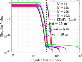
Figure 3 illustrates the DoFs and EDoFs in SPD-MIMO, showcasing the increased DoFs provided by the near-field effect. Specifically, in Figure 3(a), we present the singular values of the MIMO channel matrix for different link distances and numbers of antennas. Notably, the DoF of NFC is significantly higher than the value achieved by FFC, surpassing the single DoF threshold. As shown, the singular values exhibit a slow decline until they reach a critical threshold, after which they decrease rapidly. The number of dominant singular values defines the . From Figure 3(a), we can infer that as the number of antennas increases, the singular values, and thus the channel gains of the decomposed sub-channels, experience slight improvements, with converging rapidly to its upper limit (as calculated in [4]). Additionally, it is noteworthy that a shorter link distance results in a higher [4], showcasing the superiority of NFC in terms of DoF enhancement.
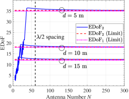
Figure 3(b) presents the plot of for SPD-MIMO in the near-field. We observe that as the number of antennas increases, of SPD-MIMO converges to its limit, which is equivalent to of CAP-MIMO [8]. This convergence occurs more rapidly for higher link distances. Remarkably, as depicted in the graph, SPD-MIMO having half-wavelength antenna spacing can achieve nearly the same as CAP-MIMO. The results in Figure 3(a) indicate that the singular values of our system satisfy , where can be approximated by the value of . This observation aligns with the findings from Figure 3(b).
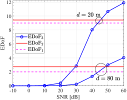
In Figure 3(c), we plot as a function of the SNR. Observe that reducing the link distance enhances , further validating the use of the near-field effect to improve channel capacity. Additionally, we note that in the high-SNR regime, can exceed and . This phenomenon arises because the non-dominant sub-channels can also support reliable communications, when sufficient transmit power resources are available.
IV-B CAP-MIMO
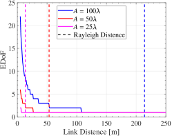
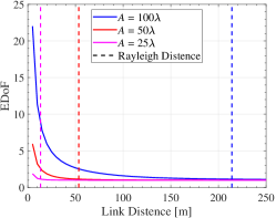
Figure 4 presents an analysis of the DoFs in CAP-MIMO systems. Due to the computational complexity associated with calculating the channel capacity of CAP-MIMO [15], we focus on illustrating and in this figure, and the numerical results for are omitted.
In Figure 4(a) and Figure 4(b), we showcase and as functions of the link distance, respectively. To differentiate between the near-field and far-field regions, we mark the Rayleigh distance in both graphs. The figures demonstrate that both and can be enhanced by either increasing the aperture sizes of the transceivers or reducing the link distance. These strategies align with commonly employed techniques for supporting NFC. A notable observation from the comparison of Figure 4(a) and Figure 4(b) is that the curves for follow similar trends to those of , corroborating the findings from Figure 3(b).
V Conclusion and Promising Research Directions
In this article, we have conducted an in-depth investigation into the performance of MIMO NFC from a DoF perspective. We began by elucidating the spatial DoFs achievable in near-field SPD-MIMO and exploring how these increased DoFs can be exploited for enhancing the channel capacity. Next, we analyzed and compared three DoF-related performance metrics, namely , , and , to their far-field counterparts for demonstrating the superiority of NFC in terms of spatial multiplexing and channel capacity. To further explore the potential of MIMO NFC, we extended these results to CAP-MIMO to determine the upper limit of performance. We have deepened the understanding of the augmented spatial DoFs offered by the near-field effect, with the hope of inspiring further innovations in this field. There are still numerous open research problems in this area, which are summarized from three aspects.
-
•
DoF-Based Information-Theoretic Limits: The DoF is a significant information-theoretic measure directly related to channel capacity. Exploring the DoF to characterize the fundamental information-theoretic limits of NFC, including deriving the achievable DoF region, can provide essential insights for system design. Additionally, the pursuit of capacity-approaching transmission schemes for NFC from a DoF perspective represents a valuable endeavor.
-
•
DoF-Based Performance Analysis: Although our analysis has concentrated on point-to-point MIMO NFC, extending our investigations to multiuser scenarios holds the potential of offering valuable insights into the spatial DoFs in more complex communication setups, presenting a promising avenue for future research. Additionally, the heuristic nature of and the computational challenges in calculating for CAP-MIMO necessitate further research efforts to derive precise physical interpretations and practical implications for these metrics.
-
•
DoF-Inspired Beamforming Design: Effective beamforming designs are crucial for fully harnessing the increased DoFs offered by NFC. However, the computational and hardware complexities, particularly in the context of CAP-MIMO implementation, pose significant challenges. Therefore, there is a pressing need to explore scalable and computation-hardware efficient beamforming techniques that can exploit the benefits of augmented DoFs in practical NFC scenarios.
References
- [1] Y. Liu et al., “Near-field communications: A tutorial review,” arXiv preprint arXiv:2305.17751, Accessed on 25 Jul. 2023.
- [2] M. Cui, Z. Wu, Y. Lu, X. Wei, and L. Dai, “Near-field MIMO communications for 6G: Fundamentals, challenges, potentials, and future directions,” IEEE Commun. Mag., vol. 61, no. 1, pp. 40–46, Jan. 2023.
- [3] D. Tse and P. Viswanath, Fundamentals of Wireless Communication. Cambridge, U.K.: Cambridge Univ. Press, 2005.
- [4] D. A. B. Miller, “Communicating with waves between volumes: Evaluating orthogonal spatial channels and limits on coupling strengths,” Appl. Opt., vol. 39, no. 11, pp. 1681–1699, Apr. 2000.
- [5] D. Dardari, “Communicating with large intelligent surfaces: Fundamental limits and models,” IEEE J. Sel. Areas Commun., vol. 38, no. 11, pp. 2526–2537, Jul. 2020.
- [6] A. S. Y. Poon, R. W. Brodersen, and D. N. C. Tse, “Degrees of freedom in multiple-antenna channels: A signal space approach,” IEEE Trans. Inf. Theory, vol. 51, no. 2, pp. 523–536, Feb. 2005.
- [7] A. Pizzo, A., A. de Jesus Torres, L. Sanguinetti, and T. L. Marzetta, “Nyquist sampling and degrees of freedom of electromagnetic fields,” IEEE Trans. Signal Process., vol. 70, pp. 3935–3947, 2023.
- [8] Z. Xie et al., “Performance analysis for near-field MIMO: Discrete and continuous aperture antennas,” arXiv preprint arXiv:2304.06141, Accessed on 12 Apr. 2023.
- [9] T. Muharemovic, A. Sabharwal, and B. Aazhang, “Antenna packing in low-power systems: Communication limits and array design,” IEEE Trans. Inf. Theory, vol. 54, no. 1, pp. 429–440, Jan. 2008.
- [10] S. Verdú, “Spectral efficiency in the wideband regime,” IEEE Trans. Inf. Theory, vol. 48, pp. 1319–1343, Jun. 2002.
- [11] D.-S. Shiu, G. Foschini, M. Gans, and J. Kahn, “Fading correlation and its effect on the capacity of multielement antenna systems,” IEEE Trans. Commun., vol. 48, no. 3, pp. 502–513, Mar. 2000.
- [12] J. Xu, X. Mu, and Y. Liu, “Exploiting STAR-RISs in near-field communications,” IEEE Trans. Wireless Commun., Early Access, 2023.
- [13] A. Pizzo and A. Lozano, “On Landau’s eigenvalue theorem for line-of-sight MIMO channels,” IEEE Wireless Commun. Lett., vol. 11, no. 12, pp. 2565–2569, Dec. 2022.
- [14] Y. Jiang and F. Gao, “Electromagnetic channel model for near field MIMO systems in the half space,” IEEE Commun. Lett., vol. 27, no. 2, pp. 706–710, Feb. 2023.
- [15] Z. Wan, J. Zhu, Z. Zhang, L. Dai, and C. B. Chae, “Mutual information for electromagnetic information theory based on random fields,” IEEE Trans. Commun., vol. 71, no. 4, pp. 1982–1996, Apr. 2023.