Analytical study of optical dielectric interfaces for sensing applications
German E. Caro
Eduardo O. Acosta
Francisco E. Veiras
Liliana I. Perez
Abstract
Dynamic optical sensors, as those based on the reflectivity of isotropic dielectrical interfaces, can be useful for measuring small changes in the refractive index of fluid media. Exact and approximated explicit formulas for their sensitivity are developed. These expressions clarify the influence of each of the constructive parameters of the device, both in partial and in total reflection. It is analytically found that sensitivities are always greater when the angle of incidence approaches the angle of total reflection. It is also demonstrated that close to the critical angle for both types of reflection, the sensitivity of the p mode is greater than that of the s mode.
††journal: Optik
1 Introduction
Refractometry is a valuable method used in optics to determine the index of refraction of materials, which is important for assessing their composition [1][2] and purity[3]. Various techniques exist for sensing small variations in the index of refraction of a medium, including surface plasmon resonance [4], dielectric optical interfaces [5], and interferometric methods [6]. In particular [7] presented an experimental paper based on the reflectivity of optical interfaces for ultrasound detection without providing a theoretical background to allow further optimizations. Consequently, it’s possible to detect ultrasound waves by measuring small variations in refractive index. While transducers are often used for this purpose, they have some limitations in sensitivity, bandwidth, and signal-to-noise ratio [8]. On the other hand, optical methods based on refractometry offer a promising solution to these issues, and current developments aim to improve their performance in all areas [7] [9]. These sensors can be optimized to sense small changes in the refractive index of fluids.
One of the simplest and most effective sensor schemes to sense changes in the refractive index is based on reflectivity between two linear dielectric media. Previous studies have explored the sensitivities for intensity and phase numerically [5] and experimentally
[7][10]. Numerical results indicate that the greatest sensitivities are achieved at angles close to the critical angle [5]. As far as we know, this manuscript presents the first analytical approach to this problem. Our work enables to accurately identify the conditions that result in maximum sensitivity, as detailed in the following sections.
In Section 2, we do a brief review to define the notation used in the following sections. In Section 3 we present the theoretical framework and obtain the exact analytical expressions for the sensitivity of a dielectric interface in both partial and total reflection. Moreover, we obtain approximate expressions for the sensitivity that allow us to perform a deeper analysis. In order to illustrate the importance of these expressions, in Section 4 we perform numerical analysis based on them. Finally, we present the conclusions.
2 Reflection and refraction
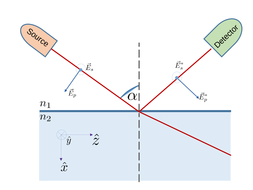
In this work, we consider that a monochromatic beam of known amplitude and polarization impinges with an angle on the interface between two dielectric media with indexes of refraction and (Fig. 1).
Figure 1: Sensor scheme: and are the refraction indexes of the media. The light impinges on the interface with an angle of incidence . and are the electric fields perpendicular and parallel to the incidence plance.
For these kinds of sensors, the relevant magnitude is the reflection coefficient. For an interface between two linear isotropic media, the reflection coefficients are functions of , and and depend on the polarization modes TE () and TM () [11][12]
(1)
(2)
From Eqs. 1 and 2 there is an angle if that makes the value inside the square root negative.
(3)
For angles of incidence smaller than the critical angle, Eqs. 1 and 2 are real, with a value between and . Nevertheless, for angles greater than the critical angle, the coefficients are complex numbers with moduli and the phases are functions of , , and the polarization mode. In this last condition, there is no transmitted wave into the second medium.
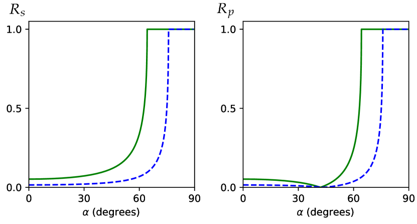
Figure 2: Moduli of Fresnel coefficients for and modes as a function of for and two different values of : water (\hdashrule[0.5ex]0.3cm0.3mm 1.3330) and water-glicerine 75% (\hdashrule[0.5ex]0.4cm0.3mm0.1cm 0.05cm1.4353).
Fig. 2 shows the moduli of the reflection coefficients for and modes as a function of with nm (D line). FK51A glass was chosen as the incident medium (), and two values for the refractive index of the second medium: water (useful when dealing with medical applications, since it’s a value close to the one from biological tissue [13]) and a mix of water-glicerine () with [14].
Total internal reflection occurs when the angle of incidence is greater than the critical angle and there is no transmitted field. Then, the phase of the reflection coefficients and are given by [15]
(4)
and
(5)
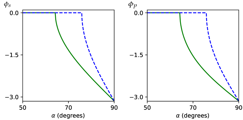
Figure 3: Phase of the Fresnel for and modes coefficients for the indexes considered in Fig. 2, as a function of for and =1.3330 (\hdashrule[0.5ex]0.3cm0.3mm) and =1.4353 (\hdashrule[0.5ex]0.4cm0.3mm0.1cm 0.05cm).
The phases of the Fresnel coefficients for the and modes are drawn in Fig. 3. In both Figs. 2 and 3, the slope presents rapid changes for angles of incidence close to the critical angle ( for water and for water-glicerine mixture).
3 Sensitivity
The proposed sensors aim to dynamically detect small changes in the refractive index of the second medium. The changes in can be studied by analyzing the variations in the amplitude or phase of the reflected beam. When developing this kind of sensor, it’s necessary to understand under which experimental conditions the detector can measure variations of with the greatest sensitivity.
From Section 2, it can be observed that for incidence angles close to the critical angle, both the reflected field in amplitude and phase exhibit a strong dependence on the angle of incidence and the refractive index of the second medium, while keeping the refractive index of the first medium constant.
When designing this type of sensors, it is necessary to study how sensitive the geometry is to changes in . It is important to determine the optimal angle of incidence and polarization to detect small variations in ().
For a fixed angle of incidence and , the relative change in the detected magnitude is related to the sensitivity and the change in refractive index according to the sensitivity definition proposed by [7] for this type of sensors:
(6)
Here, represents the intensity of the incident beam, and is the change in the detected intensity. The sensitivity is evaluated at a constant and angle of incidence (), as well as the mean value of .
In the case of small variations (), a good estimation of the sensitivity can be obtained from:
(7)
Here, is evaluated with the parameters and at the mean value of ().
The sensitivity depends on the type of reflection (partial or total), polarization mode ( or ), and the specific experimental setup employed. In the following subsections, explicit expressions are presented for each of the possible conditions, and the dependence on the parameters , , and is analyzed.
3.1 Partial reflection
In the case of partial reflection, the scheme is based on sensing the intensity variations of the reflected beam for each mode of polarization. For angles of incidence smaller than the critical angle, the intensity of the reflected beam is
(8)
where are the reflectivities of and modes, respectively. Namely
(9)
Since can be expressed in terms of the variation of the index
(10)
the sensitivity for each mode in partial reflection is given by
(11)
By means of Eqs. 1,2, 9 and 11 the sensitivity for both modes in partial reflection can be written explicitly as
(12)
(13)
Analysing Eqs. 12 and 13, it’s seen that both expressions for the sensitivity have a pole in ., calculated for the indexes and . While the sensitivity for the mode is always negative and never zero, the sensitivity for the mode has two zeroes far from the critical angle.
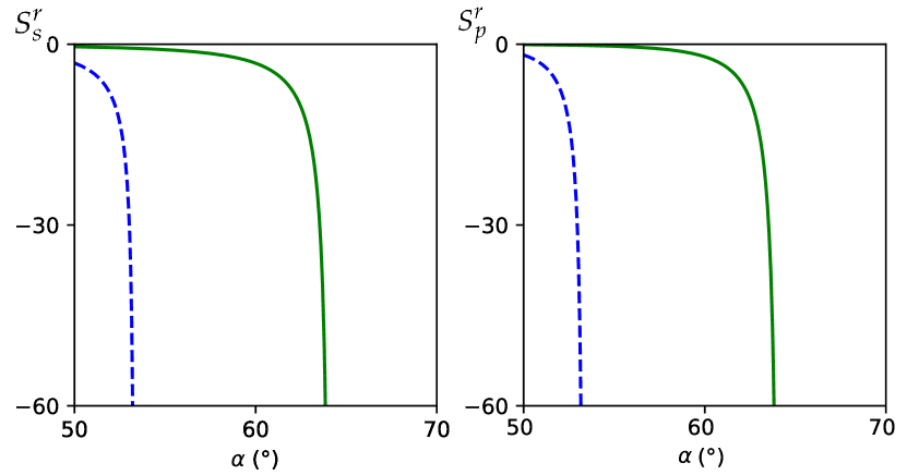
Fig. 4 shows the behaviour of and for two sensors in partial reflection. Two types of glasses were considered: FK51A () and BAF10 (). In both cases, the second medium is water. The figure was made in a range around for both glasses to highlight the divergence of and .
Figure 4: and as a function of . and two values corresponding to different commercial glasses =1.4865 (\hdashrule[0.5ex]0.3cm0.3mm) with and =1.6699 (\hdashrule[0.5ex]0.5cm0.3mm0.1cm 0.05cm) with .
Although Eqs. 12 and 13 are simple enough to be used in daily calculations, it’s not straightforward to extract from them which are the conditions that lead to greater sensitivities.
Since Fig. 4 shows is greater near the critical angle, it was decided to make a Taylor expansion around in Eqs. 12 and 13.
This way, the sensitivities expressions around the critical angle can be written in a very simple and clear way (see Appendix A)
(14)
(15)
Near the critical angle, when the independent term of Eqs. 14 and 15 can be ignored, the quotient is greater than one. Thus, around the critical angle, the mode has greater sensitivity than the mode.
It’s clearly seen that the sensitivity has a vertical asymptote for both modes at and is higher when approaches to .
The approximations obtained are valid for angles of incidence close to . For example, in Table 1 the distances to the critical angles are shown if differences of between approximated and exact sensitivities are desired.
s mode
p mode
1.4865
0.131
0.086
1.6699
0.200
0.083
Table 1: (degrees) for and the values for used in Fig. 4 if a difference of between approximated and exact sensitivities is desired.
3.2 Total internal reflection
When the incidence angle is greater than , the reflected beam has a phase difference with regard to the incident beam. Information about this phase can be obtained by interferometric methods.
In conditions of total reflection, the incident beam is split into two beams with the same intensity and phase difference . One of them is used as a reference beam and the other impinges on the interface. The interference pattern between the reference and reflected beam is,
(16)
where is the phase difference between the incident and the reflected beams. As in partial reflection, the dependence of on can be obtained
(17)
Interferometers can be adjusted to their maximum response when . In this condition
(18)
Therefore, from Eq. 7, the sensitivity for total internal reflection sensors is
(19)
Applying Eq. 19 to Eqs. 4, 5, explicit expressions for the sensitivities for the and modes are obtained.
(20)
(21)
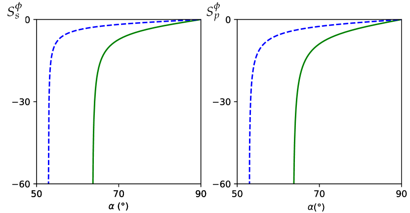
Eqs. 20 and 21 show there is no value of such that . It should be noted that Eq.21 can be nullified for an angle outside the range of total reflection. Fig. 5 shows that for the and modes grow for angles of incidence close to the critical angle corresponding to each medium. Both modes have an unique vertical asymptote at . This behaviour is similar to that for partial reflection.
Figure 5: and as a function of . and two values corresponding to different commercial glasses =1.4865 (\hdashrule[0.5ex]0.3cm0.3mm) with and =1.6699 (\hdashrule[0.5ex]0.5cm0.3mm0.1cm 0.05cm) with .
The behaviour of the sensitivity close to the critical angle can be analysed, taking into account the Taylor series around at first order (see Appendix B)
(22)
(23)
As in partial reflection , greater than one. The sensitivity has a vertical asymptote for both modes at and is greater when approaches .
s mode
p mode
1.4865
3.093
2.108
1.6699
4.311
2.108
Table 2: (degrees) for and the values for used in Fig. 5 if a difference of between approximated and exact sensitivities is desired.
As in partial reflection, the approximations are good for angles of incidence close to . For example, in Table 2 the distances to the critical angles are shown if differences of between Eqs.20 and 22 and between Eqs. 21 and 23.
4 Analysis
Expressions 14 and 15 allow analysing the conditions to be fulfilled at the moment of the design of the experiment to sense changes in in partial reflection. Analogously, Eqs. 22 and 23 are the equivalent equations for total internal reflection.
Since the and modes are qualitatively similar, as shown in Figs. 4 and 5. Moreover, near the critical angle both sensitivities are proportional, and the mode is slightly superior. Consequently, only the mode will be analysed.
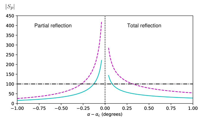
A good way to compare different designs (geometry and materials) is to graph as a function of instead of . This allows to compare the sensitivity in partial reflection and total reflection, plotting both cases in the same figure. Fig. 6 shows the sensitivity for this type of sensor for the mode, using fixed and different values for ( and ). Since it diverges at , the graphs are made up to from .
Figure 6: Sensitivity for mode as a function of for water (\hdashrule[0.5ex]0.3cm0.3mm) and water-glicerine 75% (\hdashrule[0.5ex]0.5cm0.3mm0.075cm 0.05cm with ).
In partial reflection, the sensitivities are higher. Also, the closer is to , the greater the sensitivity, both in partial reflection and in total reflection.
In an experimental setup, the intensity is the value to be measured in partial reflection. On the other hand, the phase is the measured magnitude in total reflection by interferometric methods. If these magnitudes are detected with a relative uncertainty of 1/1000 and the variations of are of the order , then the setup requires a minimum sensitivity of .
Table 3 shows the results for two values of to get a sensitivity of 100. For example, if and , the angle of incidence has to be for partial reflection. On the other hand, for total reflection, the angle of incidence has to be for mode. This again shows that the sensitivity is greater for partial reflection.
Partial reflection
Total reflection
1.3330
0.129
0.083
1.4353
0.270
0.136
Table 3: (degrees) for and the values of Fig. 6 when .
5 Conclusions
This work studies the sensitivity of a sensor based on an interface between two isotropic dielectric media to measure small variations in the refractive index of the refracting medium. An analytical expression for the sensitivity is derived, providing a valuable tool for predicting its performance under different design parameters.
A first analysis reveals that the sensitivity is maximized for angles of incidence near the critical angle of total internal reflection, regardless of whether the reflection is partial or total. It is also found that the p-polarized mode is more sensitive than the s-polarized mode in all cases, which is consistent with our prior numerical research in this area. In addition, it is observed that the sensor’s sensitivity is higher in partial reflection than in total reflection. This conclusion is supported by both graphical and analytical evidence.
To clarify the functional dependence of the sensor’s sensitivity near the critical angle, an approximate expression is developed. These expressions provide a clear and intuitive visualization. The approximation turns out to be more accurate in total reflection than in partial reflection.
Moreover, we also found that the refractive indices of the mediums provide higher sensitivities when y closer to . This is also enhanced when both indices are large. However, as the indices of refraction become closer, the critical angle also becomes larger.
By means of the expressions derived, this study provides valuable insights into the design and performance of this type of sensor.
Appendix A Approximation in partial reflection
Both expressions can be written as a product of two factors: only one of them diverges for . The other factor that goes to zero is approximated at first order. The sensitivity for and modes (Eqs. 12 and 13) can be rewritten
(24)
(25)
where
(26)
is a parameter that approaches zero when the incidence angle gets closer to the critical angle and where
(27)
(28)
and
(29)
Since y are finite when approaches zero, it’s possible to do a first order Taylor expansion around such that
In consequence of Eqs. 30, 31, 32, 33, 34, 36 an approximated expression for the sensitivity as a function of the closeness to the critical angle was obtained.
(37)
(38)
Appendix B Approximation in total reflection
As was the case with the exact expression for the sensitivity in reflectivity, in the case of the sensitivity in phase it’s not straightforward to visualize which parameters or combination allows obtaining the maximum sensitivity. Using the same techniques that in Appendix A to approximate these expressions close to ,
the sensitivity in phase for the and modes (Eqs. 20 and 21) can be rewritten as
(39)
(40)
where the auxiliary functions y are
(41)
(42)
calling
(43)
Since and are finite when approach zero, it’s possible to take a Taylor expansion of first order around such that
(44)
and analogously for . where
(45)
(46)
Also, both and don’t depend on , so the next Taylor term is null.
Using
(47)
and approximating at first order around
(48)
The approximated sensitivities in phase are
(49)
(50)
References
[1]
P. Patnaik, Dean’s analytical chemistry handbook, McGraw-Hill Education,
2004.
[2]
J. Wilms, N. Roth, B. Weigand, S. Arndt, Determination of the composition of
multicomponent droplets by rainbow refractometry, in: 12th International
Symposium on Applications of Laser Techniques to Fluid Mechanics, 2004.
[3]
R. N. Compton, M. A. Duncan, Laser experiments for chemistry and physics,
Oxford University Press, 2016.
[4]
H. Liang, H. Miranto, N. Granqvist, J. W. Sadowski, T. Viitala, B. Wang,
M. Yliperttula, Surface plasmon resonance instrument as a refractometer for
liquids and ultrathin films, Sensors and Actuators B: Chemical 149 (1) (2010)
212–220.
[5]
E. C. Vallejo, C. C. Romano, F. Veiras, L. C. Brazzano, Dielectric optical
interfaces in total internal reflection for ultrasound detection, in: 2021
IEEE UFFC Latin America Ultrasonics Symposium (LAUS), IEEE, 2021, pp. 1–4.
[6]
A. Rosenthal, S. Kellnberger, D. Bozhko, A. Chekkoury, M. Omar, D. Razansky,
V. Ntziachristos, Sensitive interferometric detection of ultrasound for
minimally invasive clinical imaging applications, Laser & Photonics Reviews
8 (3) (2014) 450–457.
[7]
X. Zhu, Z. Huang, G. Wang, W. Li, D. Zou, C. Li, Ultrasonic detection based on
polarization-dependent optical reflection, Optics letters 42 (3) (2017)
439–441.
[8]
G. Wissmeyer, M. A. Pleitez, A. Rosenthal, V. Ntziachristos, Looking at sound:
optoacoustics with all-optical ultrasound detection, Light: Science &
Applications 7 (1) (2018) 1–16.
[9]
W. Song, F. Yang, C. Min, S. Zhu, X. Yuan, Toward ultrasensitive, broadband,
reflection-mode in vivo photoacoustic microscopy using a bare glass, Laser &
Photonics Reviews 17 (1) (2023) 2200030.
[10]
J.-Y. Lin, Solution refractive index sensor based on high resolution
total-internal-reflection heterodyne interferometry, Sensors and Actuators A:
Physical 241 (2016) 190–196.
[11]
M. Born, E. Wolf, Principles of optics: electromagnetic theory of propagation,
interference and diffraction of light, Elsevier, 2013.
[12]
J. Lekner, Theory of reflection, Springer Series on Atomic, Optical, and Plasma
Physics 87 (2016).
[13]
S. L. Jacques, Optical properties of biological tissues: a review, Physics in
Medicine & Biology 58 (11) (2013) R37.
[14]
J. Rumble, et al., CRC handbook of chemistry and physics, CRC Press llc Boca
Raton, FL, 2017.
[15]
J. Peatross, M. Ware, Physics of light and optics: a free online textbook, in:
Frontiers in Optics, Optical Society of America, 2010, p. JWA64.