High-speed electrical connector assembly by structured
compliance in a finray-effect gripper
Abstract
Fine assembly tasks such as electrical connector insertion have tight tolerances and sensitive components, requiring compensation of alignment errors while applying sufficient force in the insertion direction, ideally at high speeds and while grasping a range of components. Vision, tactile, or force sensors can compensate alignment errors, but have limited bandwidth, limiting the safe assembly speed. Passive compliance such as silicone-based fingers can reduce collision forces and grasp a range of components, but often cannot provide the accuracy or assembly forces required. To support high-speed mechanical search and self-aligning insertion, this paper proposes monolithic additively manufactured fingers which realize a moderate, structured compliance directly proximal to the gripped object. The geometry of finray-effect fingers are adapted to add form-closure features and realize a directionally-dependent stiffness at the fingertip, with a high stiffness to apply insertion forces and lower transverse stiffness to support alignment. Design parameters and mechanical properties of the fingers are investigated with FEM and empirical studies, analyzing the stiffness, maximum load, and viscoelastic effects. The fingers realize a remote center of compliance, which is shown to depend on the rib angle, and a directional stiffness ratio of . The fingers are applied to a plug insertion task, realizing a tolerance window of mm and approach speeds of m/s.
1 Introduction
The installation of cables and wire harnesses has substantial industrial demand, especially as electrification of automobiles and household appliances increases. While the pre-production of cable harnesses (cutting, mounting of wire seals and attachment of cable heads) can be achieved with specialized machinery [1], installation is today largely manual work [2].
Cable installation is challenging to automate due to the high variety in connectors [2] which can lead to small batch sizes [1]. The manipulation of cables also introduces technical challenges, where cable routing requires perception and planning methods for deformable linear objects [1, 3]. However, connector insertion is a critical functionality for all cable installation tasks. It is also challenging: it requires coordinated vision and touch when done by humans [3], and robotic solutions often require a combination of sensors (vision [1], tactile [4, 5, 6], or force [7]) and application-specific finger design [8, 9, 10].
The challenges in the gripping, alignment, and insertion of electrical connectors are largely shared by other fine assembly tasks. In both cases, alignment errors can cause failed assembly [10], requiring the use of some error compensation methods [11]. Assembly force must be applied to bring together a snap or friction fit without causing jamming [11]. Inserting in obstructed and complex environments often imposes tight space requirements on the gripper, and the need to leave the inserted portion free often requires a fingertip grip [12].
These challenges can be partly handled by compliance. In insertion, compliance can compensate misalignment between gripped part and socket [12, 11]. Compliance can be active or passive [13, 11], where passive compliance is the intrinsic mechanical compliance of the physical structure, and active compliance is achieved by feedback controller design. A relevant example for compliance is the remote center of compliance (RCC) [14, 12], which allows self-alignment in insertion tasks [15]. Active compliance, such as impedance or admittance control can adapt the relative pose according to contact forces [16, 11].
The major advantage of active compliance is the possibility to digitally change compliance, e.g. adjusting the RCC location to improve performance [13] or using general non-diagonal stiffness matrices [17]. The disadvantages of active compliance are the relatively high costs and the limited bandwidth [13], which typically leads to higher collision forces. In contrast, passive compliance has almost no bandwidth limits, allowing high-speed contact transitions [18]. However, many materials used in soft robotics have viscoelastic effects [19], which can affect high-speed performance. Physical compliance also reduces the positioning accuracy and ability to detect contact [11, 20], but supports motion strategies which exploit contact such as mechanical search [21] with self-alignment [22].
Passive compliance can be integrated at various locations in the robot; the joints [23], flange [12], fingers [19] or environment [24]. By integrating the compliance directly proximal to the contact, the sprung inertia is reduced, reducing inertial forces at high accelerations. The remote center of compliance can be integrated in the robot flange, but then gripper contributes to sprung inertia, typically contributing kg of inertia. On the other hand, soft fingers can provide proximal compliance, as well as realizing a larger contact area over variation in the gripped object’s surface geometry [19].
Soft fingers can be realized with silicone [25, 26, 27, 28], often with the objective of universal gripping. However, these silicon-based soft fingers often render a very low stiffness [29], making it difficult to realize the repeatability or assembly forces needed in many fine assembly tasks [11]. Soft fingers can be constructed by additive manufacturing, which can be used to construct monolithic soft pneumatic fingers [30] or flexure-based grippers [29].
Designing passive compliance for assembly is typically done in terms of the spatial stiffness rendered on the gripped object, which affects collision force [18] and alignment error compensation [22, 31]. Modelling of soft fingers is often done with continuum mechanics, Cosserat rod theory or FEM [32], which can support kinematic design and control, but often does not consider rendered stiffness. The parallel or series combination of elemental stiffness can be used to analyze rendered stiffness [31, 24], but this is difficult to scale to complex soft fingers. The limited a priori design methods for rendered directional compliance leads to a need for iterative testing for a specific task or part [33]. However, this iterative testing can be accelerated with fast prototyping methods like fused deposition modelling [24, 34], which can also integrate structural passive compliance in monolithic structures with flexures [29].
This work proposes structured compliant fingers for electrical component assembly, using fused deposition modeling to produce low-cost monolithic devices which can be easily integrated to parallel grippers. Compared with soft fingers which target universal gripping, either silicone-based [25, 26, 27, 28] or finray-based [34], these fingers realize a structured compliance for passive alignment while providing sufficient force in the assembly direction. Compared with sensorized fingers for plug insertion [35, 36], the proposed compliance allows a larger tolerance window and higher speed. In contrast to plug insertion approaches using active compliance, which can take up to s from first contact to insertion [37], the passive compliance allows a successful assembly of the connectors in s. This paper also provides a taxonomy and detailed requirements of the connector insertion problem, whereas existing work [9, 10, 1] focus on wire harness design and production, not connector mating.
A previous version of this paper was submitted to the 2023 IEEE/ASME International Conference on Advanced Intelligent Mechatronics [38]. This paper adds analysis of the connector assembly problem, FEM and emprical identification of the directional finger stiffness, empirical investigation of viscoelastic effect, as well as assembly applications with higher speeds and a wider range of components.
The paper is organized as follows. Section 2 categorizes the parameters of the plugs used in this work, parameters occurring in the assembly task, and describes the steps of the assembly process. Section 3 introduces the final gripper design, derived from the finray-effect, where the design parameters, the design and manufacturing process, and problems are described. A range of applications to verify the gripper’s abilities are presented in Section 5, consisting of repeatability and robustness experiments to determine design parameters which achieve the widest tolerable scale of misalignment. Finally, the conclusion and future work is given in Section 6.
2 Electrical connector problem description
This section analyzes the problem of connector assembly, providing a taxonomy of electrical connectors and the assembly process itself.
2.1 Taxonomy of connectors
| Property | Effects | Possible values | |
| Connector | Fit and tolerances | Search strategy, req’d assembly force | Press, running, transition |
| Plug exposed after insert | Grip location in insertion | Flush, mm | |
| Cable gland orientation | Grip location and free space | Straight, right angle | |
| Pin height | Search strategy | Flush, mm | |
| Locking feature | Insertion, validation | Clip, lever | |
| Task | Plug availability | Grasp strategy, finger design | magazine, on table, cluttered |
| Socket availability | Tolerances, search strategy | fixed position, in workpiece, free space | |
| Space requirements | Finger dimensions, robot strategy | free space dimensions | |
| Cable handling | Finger design, expected force profile | need insert clips, need to pull cable | |
| Validation | Insert strategy | Is a validation (e.g. push-pull-push) required? |
While there is large variation in connector design [2], the parameters summarized in Table 1 have a significant influence on the finger design and strategies for grasping, searching, or insertion.
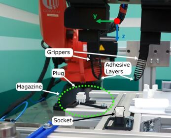
Some parameters are shown visually in Figure 2, left, which shows an inserted plug. The amount that the cable head extends from the socket after insertion limits the feasible gripping area. The cable gland can have different orientations, either straight out or in a right angle into the plug, which changes what space must be left free by the finger design. The cable type can be categorized as either a single-, ribbon-, or multi-cable. Furthermore, the pin height inside the plug and/or socket can result in collision and jamming for some search strategies. Additional locking features, such as levers or clips, may require additional assembly force or post-processing to secure. The tolerances between the plug and socket influence the search strategy and required assembly force.
2.2 Categorization of assembly task
There are additional parameters in typical connector assembly tasks which affect the design. How the plug is supplied affects the uncertainty in grip pose, as the plug could either be fixed rigidly, e.g. in a magazine, lying freely on the table or placed in a cluttered environment. Similarly, the socket could be either be in a fixed position, integrated in a workpiece or in a magazine. Further, space limits from the environment can limit both the finger dimensions and robot search strategy. During assembly, additional cable and wire handling has to be considered, e.g. intermediate clips or cable straightening. After successfully mating the components additional testing could be necessary, e.g. push-pull-push of the cable.
2.3 Grip, search, and insert strategies
The complete assembly process is considered in three stages: grip, search, and insert. From an initial position, the plug is gripped. Without a magazine or jig providing a constant and known pose of the plug, a known pose or at least the orientation of the plug inside the grip should be established within the tolerances of the insertion process.
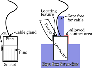
The grasping strategy includes aspects of the finger design seen in the right of Fig. 2: (i) what contact area between the plug and finger can be used. Multiple grasping strategies are possible here, either a pinch contact or parallel grasp of the wires or the cable head, (ii) what space around the connector must be kept free, (iii) are locating features needed to provide either repeatable position or sufficient assembly force? In addition to the fingertip design, the grasping strategy may include (i) a magazine for providing the plug in a semi-repeatable way and (ii) an adjustment strategy to ensure the connector is in a repeatable position in the fingers.
The search strategy should achieve alignment of the plug and socket. When using mechanical search, the search strategy should be designed considering: (i) the variation in pose that needs to be covered with the strategy, (ii) the initial contact between plug and socket, which can be a point, line or planar contact depending on how the plug is presented, (iii) the height of the pins, which could be bent if contacted by the tip of the plug, (iv) validating that the plug has successfully slipped into the socket after the alignment.
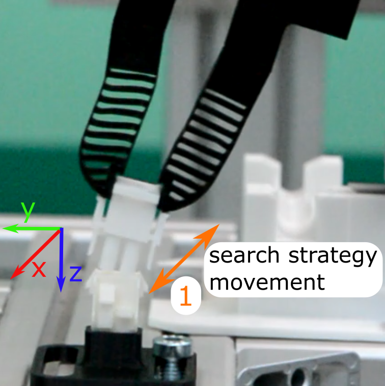
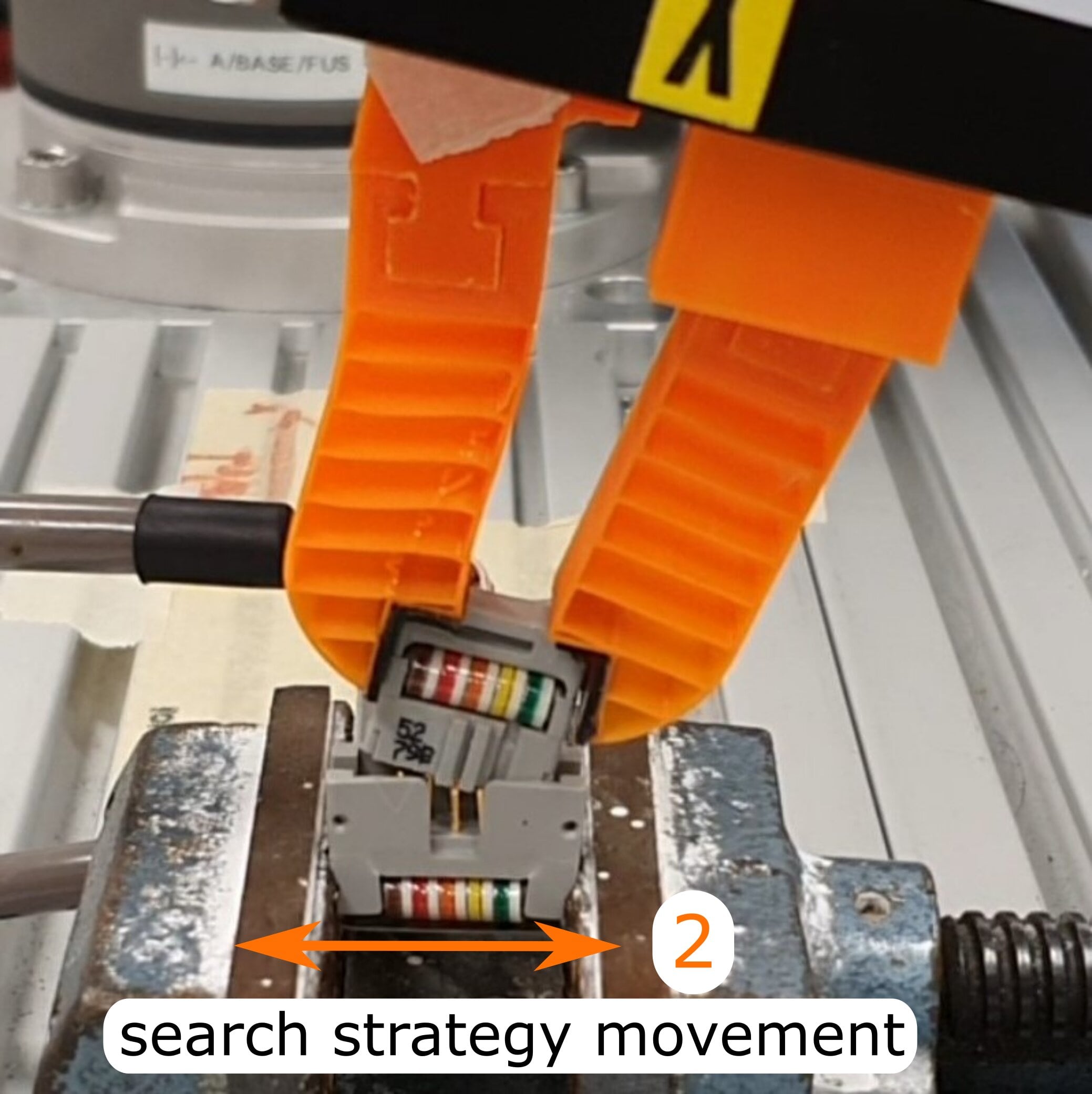
The mechanical search strategy used here is shown in Fig. 1. Initial contact is made with a tilted plug, such that the corner of the plug lightly presses on the edge of the connector, Fig. 1(a). A motion in the x-direction allows the plug to slip into the socket when aligned. Next, contact is established with the sides of plug and socket, realized by a motion in the y-direction, Fig. 1(b). At this point, the leading corner of the plug should be slightly inserted and resting on the edge of the socket. The search strategy used in this work utilizes an open-loop position control, without the use of force feedback.
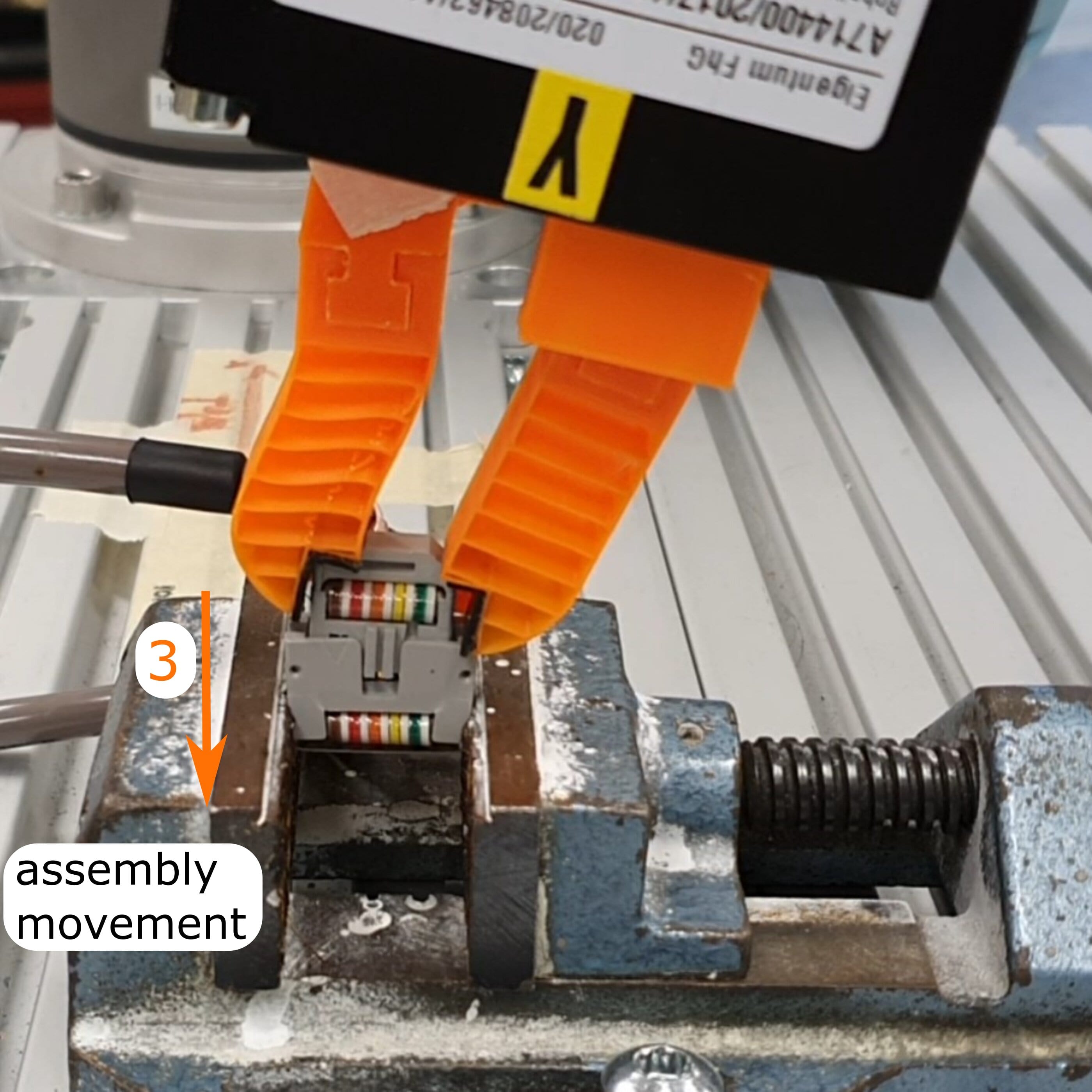
For the insertion phase following aspects should be considered: (i) the finger design should be able to avoid jamming of the connectors. For this, compliance, either active or passive, could be suitable, where the plug is able to rotate inside the socket due to the contact. (ii) The assembly force should not exceed a certain threshold, to avoid damaging the parts, which can also be realized by the finger compliance.
3 Design of Compliant Finray-effect Grippers
In this section, we describe the modification and parameterization of a finray-effect gripper [39] to meet the requirements of Section 2.1. Where classical finray-effect grippers use an enveloping grip where deformation adapts to variation in surface geometry of grasped parts [34], we propose a design where the components are grasped at the fingertip and rendered compliance on a gripped part supports mechanical search, passive alignment, while providing sufficient force in the assembly direction.
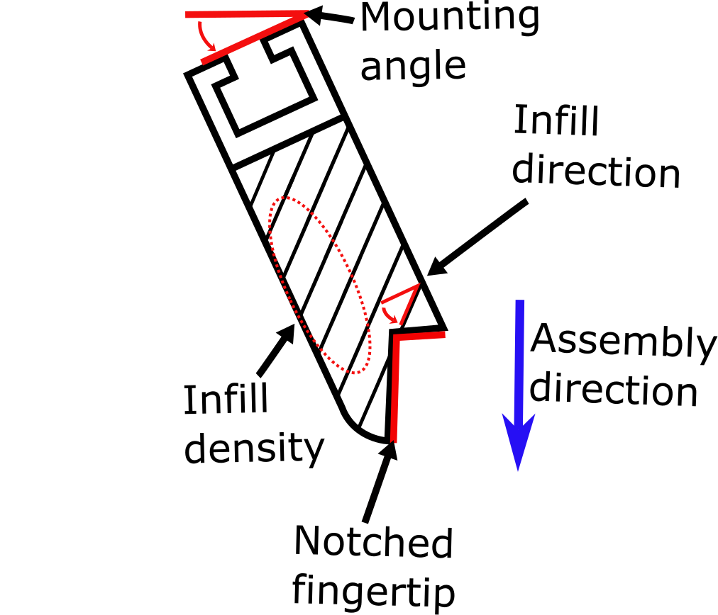
Considering the requirements and constraints in Sec. 2, the finray design is adapted with the flexibility of 3D printing to optimize the following design parameters, seen in Figure 3(a): (i) fingertip design, (ii) rib angle / infill direction, (iii) rib density / infill density, (iv) finger mounting angle.
3.1 Modified Finray Design
The finray-effect gripper mimics the deformation of fish fins, which are composed by two outer walls forming a V shape. Between the bones, crossbeams are placed which determine the mechanical properties of the finray-effect gripper. The side walls of the standard finray-effect gripper bend from contact when grasping convex parts, which results in a deformation of the base and tip towards the applied force [39]. However, the standard V-shaped finray design is not ideal for the requirements here. Here, an object should be grasped at the fingertip, capable of applying high forces in the assembly direction and offering a lower stiffness laterally to compensate misalignment.
When a flat object is grasped with a V-shaped fingertip, the assembly forces are carried only by friction, which may be insufficient for small components with small allowed grasping contact areas. A form-closure fingertip can therefore support higher assembly forces. Furthermore, to compensate misalignment for parts grasped at the fingertip: a V-shaped fingertip is stiff in the horizontal direction, and when the finger deforms, rotation of the fingertip occurs, which could result in contact loss with the gripped part. Here, a translational deflection at the fingertip is desired to compensate misalignment while maintaining the contact between gripper and grasped part.
The V-shape finger profile is changed, instead of the outer walls approaching another towards the tip, the walls are more rectangular. With the fins, this produces a parallelogram structure which does not rotate the tip as it is displaced. Additionally, form-closure features are added at the fingertips, a shoulder which is discussed in the following Section 3.2. Due to the design of the notched fingertip, the generalizability to handle various connectors is limited, but the ability to apply forces over small contact areas is improved.
With this fingertip, a directionally-dependent stiffness can be achieved, that is the effective stiffness between gripped object and robot is higher in the assembly direction, and lower in the orthogonal directions to support mechanical search and alignment compensation.
3.2 Design Parameters
Two important parameters of the finger design are optimized to improve performance.
3.2.1 Infill Options
The most important design parameters are the infill options to adjust the density and orientation of the ribs in the finger, i.e. the infill direction, given in , and the infill density options, given in , as proposed by [34] and visualized in Fig. 3(a). This affects the bulk stiffness realized by the finger on a gripped part, effective remote center of rotation, as well as the maximum force that the finger can apply , as shown in Section 4.1.
3.2.2 Fingertip Options
An additional parameter is the form of the fingers which can either be with a rounded top, flat top, notched rounded top, flat angled or notched top with a contact plane, visualized in Fig. 3(a). The notch can be rotated by a certain degree, corresponding to the mounting angle of the finger, used to achieve a parallel contact plane with the grasped part. The size of the notch depends on the connector to be handled, an oversized notch won’t contact the plug or will interfere with insertion,and an undersized notch has a smaller contact surface and could result in an unstable grip.
While adding a notched fingertip results in form-fit contact, this limits the generalizability of connectors to be handled, which is why both characteristics have to be considered during the design phase. A notched fingertip could result in an ideal solution for one connector type, but could result in an unstable grip for other connectors.
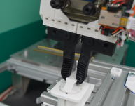
The contact surface also needs consideration: the friction of PLA+ and PETG are low, which is why additionally a thin rubber layer is applied after printing, which can be seen in Fig. LABEL:fig:robot_zoom. It is important to note, that the rubber layer consists of one adhesive layer to adhere on the contact plane of the finger. The side of the rubber tape in contact with the grasped part doesn’t have an additional adhesive applied to it, only increasing the friction coefficient.
3.3 Manufacturing Process
To allow for an easy adaptation of infill density and line directions, these parameters are set directly in the slicer program instead of CAD. Here Ultimaker Cura is used, applying a method similar to the method used in [34]. The materials used in this work are orange PLA+ and black PETG. Other materials, such as TPU and ABS were found to be unsuitable. Tests indicated TPU’s inherent compliance interferes with the effects of structured compliance, e.g. the material would be too compliant to provide the necessary stiffness in assembly direction. ABS has a tendency to warp during printing, which proved to be a major issue with the thin walls of this finger.
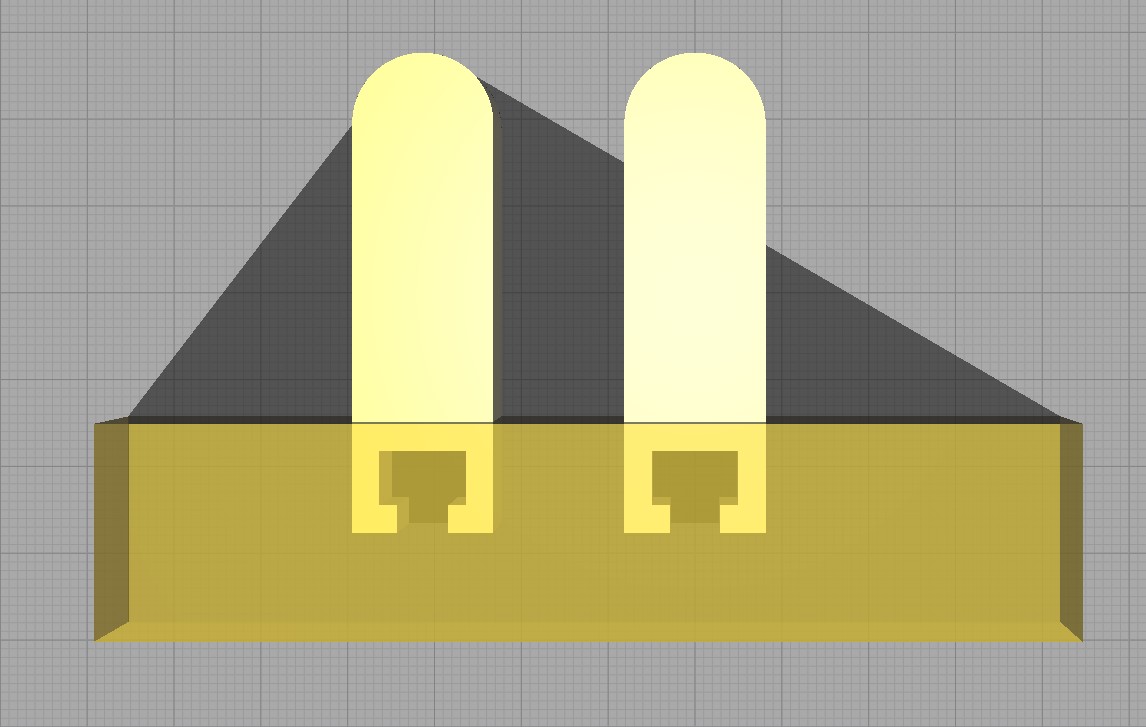
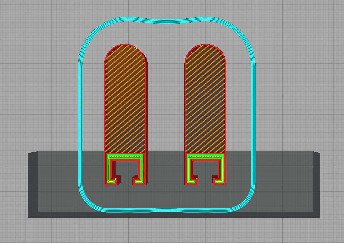
A CAD model of the solid finger is sliced in Cura, the infill type set to unconnected lines of width mm, the wall line count set to one with a line width close to the nozzle diameter of mm (less than the recommended nozzle diameter of [34]). To print the finger mount as a solid, Cura’s “support blocker” feature is applied, as visualized in Fig 3(b). The .stl/.stp/.ipt files and further details on the manufacturing are available at https://github.com/richardhartisch/compliantfinray.
4 Mechanical Attributes
In the following section, the mechanical properties of the finray-effect gripper are investigated: the stiffness of a single finger, viscoelastic effects, the maximum force and deflection until component failure is reached. The observations made here shall provide a good overview of the influence of the design parameters on the finger behaviour, providing guidance to the choice of finger parameters given the range of motion and forces required for a new application. The setups used can be seen in Fig. 4 and Fig. 5.
4.1 Single Finger Stiffness
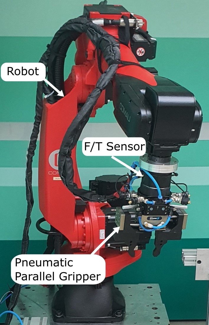
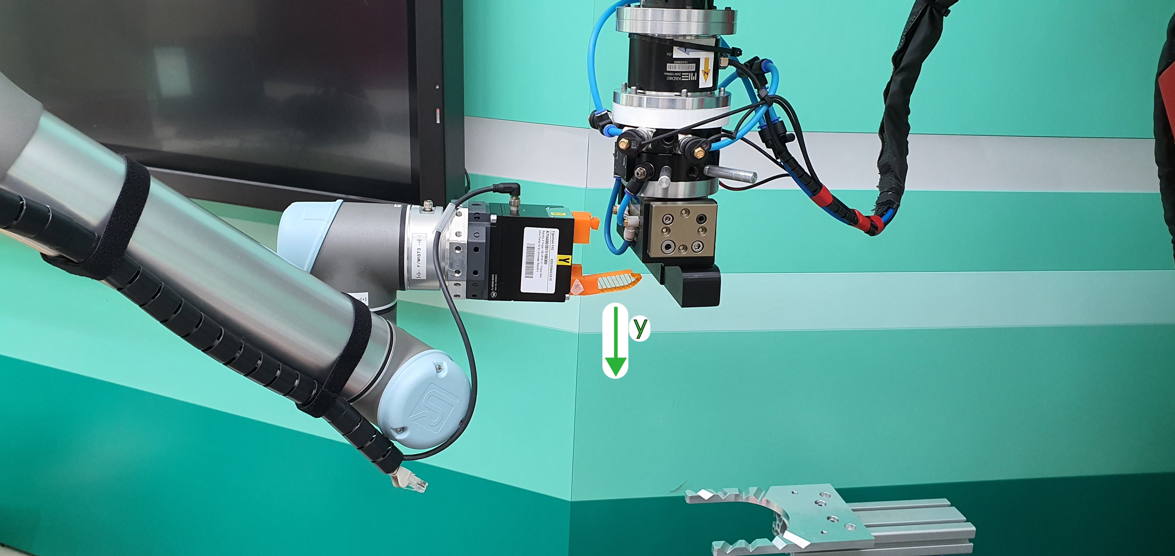
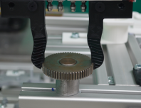
To measure the stiffness of a single finger, the edge of the Schunk gripper module is moved downwards onto the contact surface of the finger, resulting in a normal force on the contact surface, as seen in Fig. 5. The resulting force is measured via the F/T sensor seen in Fig. LABEL:fig:robot_left. To characterize the stiffness, movements in the and direction within the elastic range are applied, usually mm. The stiffness is identified with a least-squares fit for a linear stiffness model.
4.1.1 Stiffness in
To evaluate the stiffness of the experimental setup (finger fixture, robotic systems, robot pedestal), a solid finger is printed with 6 top layers, 6 bottom layers, 3 walls and a gyroid infill with a density of . Its stiffness in is identified as N/mm, a factor of 4 higher than the compliant fingers.
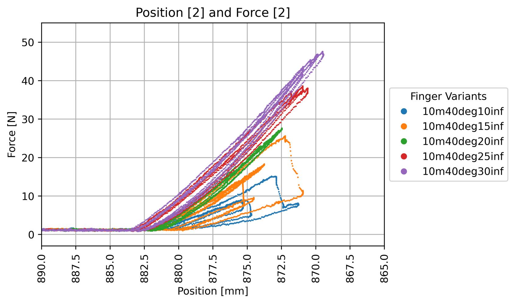
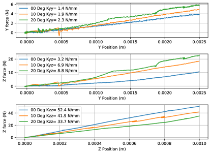
Fig. 6 shows the stiffness of infill direction over various infill density values ( to ). Here, hysteresis is strongly noticeable on lower infill densities due to plastic deformations of the finger, i.e. buckling, which can be seen in Fig. 6. An increase of stiffness with infill density is shown, where the maximum value is reached at infill direction and infill density, the maximum values tested.
Further tests of linear stiffness in for other materials and infill densities are listed in Tab. 2. Both and infill density are insufficient values for an infill direction of resulting in buckling, leading to low stiffness values, as seen in Tab. 2. Additionally, finger stiffness is more sensitive to infill density at lower infill directions, as seen in Tab. 2. As seen in Tab. 2, for the same parameters the PETG fingers achieve a lower stiffness compared to the PLA+ fingers, by roughly a factor of . The same trend in increasing stiffness over infill density is seen.
4.1.2 Directional stiffness
The remaining translational stiffnesses are measured on the setup of Fig. LABEL:fig:robot_left as
| (1) |
where and are the forces and displacements in the coordinate system shown on Fig. LABEL:fig:robot_zoom and the stiffness coupling a displacement in to a force in . Stiffnesses and are assumed to be zero, with the only off-diagonal coupling within the grip plane. is measured at N/mm for a , PLA+ finger, measured with the fingertip fixed. The stiffnesses , and are affected by the infill direction as can be seen in Fig. 7, where and N/mm.
This gives a stiffness ratio between assembly direction and transverse of , realizing a large difference in stiffness between directions. Additionally, the presence of indicates remote center of compliance (RCC) effects [31, 11]. Diagonalizing the of (1) yields the principle axis of the rendered stiffness [31], which takes a direction of , and from for , , and infill, respectively. This shows that the center of the RCC varies with the rib angles, where the lower infill directions provide an RCC farther from the gripper location.
4.1.3 Viscoelastic effects
Velocity-dependent effects were checked by loading a mm displacement in the direction with a variety of velocities, ranging from to mm/s. A simple viscoelastic model was fit as , where is the viscous term. Fitting the terms on a , PLA+ finger found N/mm and Ns/mm, indicating at high speeds, e.g. mm/s, the viscous terms will exceed N.
Infill infill infill infill infill infill Dir. 0 PETG: 0.50 - PETG: 1.133 PLA+: 2.20 PETG: 1.60 PLA+ : 1.2 PLA+: 1.95 PLA+: 3.00 10 PLA+: 1.05 - PLA+: 2.10 - PLA+: 3.00 20 PLA+: 1.533 - PLA+: 2.60 - PLA+: 3.2 30 PLA+: 1.667 PLA+: 3.00 PLA+: 3.00 PLA+: 3.20 PLA+: 3.70 40 PLA+: 0.85 PLA+: 1.22 PLA+: 3.4 PLA+: 3.6 PLA+: 3.84
4.2 Ultimate Strength and Maximum Deflection
In the following, the ultimate strength for each finger is determined and listed in Tab. 3, under which the component fails, either by breaking of the outer walls or the inner ribs or by buckling, usually of the outer walls. For this, the the tool is moved in the z-direction until a component failure occurs. The maximum deflection until component failure occurs is also listed in Tab 4. Tab. 2 and Tab. 4 display a trend that the maximum achievable deflection reduces with an increasing infill direction. The PETG fingers, which have a comparably low stiffness compared to the PLA+ fingers, achieve a comparable maximum deflection but lower maximum force due to their stiffness. Tab. 4 shows that increasing infill direction results in a lower maximum tolerable force. However, increasing the infill density results in a higher maximum tolerable force and as Tab. 4 demonstrates, also increases maximum deflection. The maximum tolerable force and the largest deflection occur for 0° infill direction with infill density.
Additionally, buckling was noticed in the single finger stiffness experiments earlier, as mentioned in Sec. 4.1, where the threshold of the unstable behaviour for at infill density is demonstrated compared to higher infill density values.
Infill 10% infill 15% infill 20% infill 25% infill 30% infill Direction 0 PETG: 12.50 - PETG: 26.50 PLA+: 56.50 PETG: 46.00 PLA+ : 26.00 PLA+: 40.50 PLA+: 72.50 10 PLA+: 26.25 - PLA+: 45.00 - PLA+: 69.00 20 PLA+: 20.50 - PLA+: 41.50 - PLA+: 55.50 30 PLA+: 16.50 PLA+: 23.00 PLA+: 34.00 PLA+: 39.00 PLA+: 51.00 40 PLA+: 15.75 PLA+: 17.00 PLA+: 32.00 PLA+: 38.50 PLA+: 43.00
Infill 10% infill 15% infill 20% infill 25% infill 30% infill Direction 0 PETG: 24.00 - PETG: 22.50 PLA+: 28.00 PETG: 27.00 PLA+ : 26.75 PLA+: 27.00 PLA+: 28.00 PLA+: 28.5 10 PLA+: 21.75 - PLA+: 23.00 - PLA+: 26.00 20 PLA+: 17.00 - PLA+: 19.00 - PLA+: 21.00 30 PLA+: 13.75 PLA+: 13.50 PLA+: 15.50 PLA+: 15.50 PLA+: 16.50 40 PLA+: 10.50 PLA+: 10.00 PLA+: 11.50 PLA+: 13.50 PLA+: 14.00
4.3 FEA
To iterate a design quickly, an efficient evaluation method is needed. Printing the proposed fingers takes roughly an hour, which can support quick iteration. However, especially in an early design phase, an Finite Elements Analysis (FEA) can provide faster evaluation of mechanical properties. This section performs FEA for the fingers, and compares to the values of the single finger stiffness in Tab. 2. For the FEA, a static stress study is done in Autodesk Fusion 360, where it is assumed that the material (Sunlu PLA+ and Verbatim PETG) is isotropic. This is inaccurate due to the working principle of the extruder, where material is dispensed as a line with which the part is built layer-wise, resulting in a non-isotropic, directional material behaviour [40], but a needed assumption for feasibility. Additionally, approximations in the mesh process may impact the results due to the thin walls.
Verbatim provides a technical data sheet with material properties determined according to various norms [41], with a tensile strength of: MPa, the Young’s modulus with: MPa, and the density of g/cm3. Since Sunlu does not provide any mechanical properties, an assumption has to be made, where an already existing material (Profile: ”Printed PolyTerra PLA Plastic”) from an external database [42] is used to model the variants, as the results of pre-tests have shown a high level of conformity with the actual material behavior. The values given are: density: g/cm3, the Young’s modulus with: MPa, the Poisson’s ratio with: , the yield strength with: MPa and the ultimate tensile strength with: MPa
The force is set, according to the stiffness in Tab. 2, so that the displacement should be mm, and a probe measures the displacement, identifying the linear stiffness as . The resulting displacement, stiffness and the relative deviation from the stiffness values in Tab. 2 of the analyzed fingers are listed in Tab. 5. Overall, the relative deviation, as seen in Tab. 5 is comparably low, deviating between 3% and 26%, demonstrating a robust performance of the FEA. The stronger deviations are discussed next.
Especially the results for infill direction and 10% infill density are noteworthy. As the first entry for infill direction and 10% infill shows, there is a considerable discrepancy between the calculated stiffness value and the measured value from the experiments. This is because of a component failure of the finger at the experiment, where the deformation is no longer elastic but plastic due to a buckling of the structure. This is not considered in the FEA explaining the discrepancy of both values. To verify the FEA of the model, another approach is needed, demonstrated in the second entry. The second entry for infill direction and 10% infill is calculated with a force value by linearly extrapolating the two prior stiffness values at infill direction and with 10% infill by , where is the infill direction, the linear effect, and the offset. With N/mm for and for , N/mm. The extrapolated stiffness at infill direction is then estimated at N/mm. This value is now used to derive the applied force for the FEA, resulting in a displacement of mm and a stiffness of N/mm resulting in a deviation of compared to the extrapolated value giving a high level of consistency. However, it becomes clear that the FEA does not correspond well to the actual measured values where instabilities occur in the real-life experiment as these are not taken into account or do not occur in the FEA, hence the deviation of .
As Tab. 5 demonstrates, the results for the PETG fingers deviate by . Since the offset is relatively constant over the variants, it could be assumed that the deviation does not come from the model or the model’s properties itself, but rather from the mechanical attributes provided by Verbatim or the missing Poisson’s ratio. As discussed before, the term ”tensile strength at yield” could be ambiguous and other important mechanical properties are missing.
The used material shows a high level of conformity with the real-life experiments, as long as no instabilities have been present, resulting in deviations between and . The relatively high deviation of is discussed before, where structural instabilities are accountable for the high deviation. While a good approximation, if the FEM setup requires substantial time (e.g. to re-construct the finger geometry otherwise determined by the slicer), the print-and-test iteration cycle may be more efficient.
Finger Type Displacement Applied Force Stiffness Relative Deviation 0° Infill Direction PLA+: 0.94 PLA+: 1.2 PLA+: 1.28 PLA+: 6 10% Infill Density PETG: 0.41 PETG: 0.5 PETG: 1.22 PETG: 59 20° Infill Direction PLA+: 1.07 PLA+: 2 PLA+: 1.43 PLA+: 7 10% Infill Density 30° Infill Direction PLA+: 1.06 PLA+: 1.733 PLA+: 1.64 PLA+: 6 10% Infill Density 40° Infill Direction PLA+: 0.46 PLA+: 0.85 PLA+: 1.85 PLA+: 54 10% Infill Density 40° Infill Direction 10% Infill Density PLA+: 0.97 PLA+: 1.801 PLA+: 1.86 PLA+: 3 0° Infill Direction PLA+: 0.74 PLA+: 1.95 PLA+: 2.64 PLA+: 26 20% Infill Density PETG: 0.54 PETG: 1.133 PETG: 2.1 PETG: 46 20° Infill Direction PLA+: 1.03 PLA+: 2.6 PLA+: 2.52 PLA+: 3 20% Infill Density 30° Infill Direction PLA+: 1.19 PLA+: 3.0 PLA+: 2.52 PLA+: 19 20% Infill Density 40° Infill Direction PLA+: 1.15 PLA+: 3.4 PLA+: 2.96 PLA+: 15 20% Infill Density 0° Infill Direction PLA+: 0.82 PLA+: 3.0 PLA+: 3.66 PLA+: 18 30% Infill Density PETG: 0.48 PETG: 1.6 PETG: 3.33 PETG: 52 10° Infill Direction PLA+: 0.91 PLA+: 3 PLA+: 3.3 PLA+: 9 30% Infill Density 20° Infill Direction PLA+: 0.94 PLA+: 3.2 PLA+: 3.4 PLA+: 6 30% Infill Density 30° Infill Direction PLA+: 1.07 PLA+: 3.7 PLA+: 3.46 PLA+: 7 30% Infill Density 40° Infill Direction PLA+: 0.94 PLA+: 3.84 PLA+: 4.09 PLA+: 6 30% Infill Density
5 Validation
This section validates the finger’s performance in assembly applications. In addition to the assembly process shown in Fig. 1, various objects shown in Fig. 8 can be assembled by the fingers. The remainder of this section iteratively validates the fingers for the assembly of a plug into socket. The setup used is the same as in the previous experiments, demonstrated in Fig. LABEL:fig:robot_zoom, implementing the working principle presented in Fig. 1.

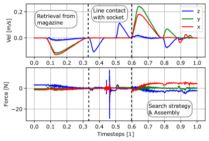
The goal is to successfully pick the plug from a magazine and assemble into a socket with and without various misalignment values. The program is intended for high-speed assembly, with tool speed values of , as seen in Fig. 9, up to over . In Fig. 9, the force peak is attributable to the forces caused during the line contact while moving in z-direction, visualized in Fig. 1(c) to fully assemble the parts.
The assembly and grasping process is summarized as follows and can be seen in Fig. LABEL:fig:robot_zoom. First, the cable is grabbed from a magazine which provides a repeatable starting point. The contact force of the fingers overcome the contact force of the spring when moving the gripper in a linear movement upwards, with which the cable is removed from the magazine. To compensate slippage during the first phase, afterwards the gripper could push the cable head slightly on the table with a linear movement downwards to ensure a contact with the upper contact surface of the finger. Now, in the second phase, assembly takes place, using the search strategy described earlier in Section 2.3. A video is available as supplementary material and at https://youtu.be/J7EGXtE54oY.
5.1 Repeatability Experiments
To test for repeatability, the assembly process is repeated 84 times with a fixed socket position, using the aforementioned UR program and manually resetting the plug in the magazine, out of which the assembly failed twice. The first failure occurred at attempt 30 and the second failure at attempt 84 which ultimately lead to a component failure of the fingers. This concludes a roughly success rate. Assumed causes are either slight slippage in the grip coming from the adhesive tape, or the kinematics of the robot. Additionally, the table on which the robot is mounted is not fixed but on wheels, which could add another level of instability, impairing the robustness.
5.2 Robustness Experiments
In the next experiments, the robustness over variation in socket position is tested, to clarify the impact of the design parameters on the robustness and tolerable range. To control the misalignment, instead of a fixed waypoint for the socket position, a variable waypoint is programmed which can be changed in each iteration. For the initial test, the boundaries of compensable misalignment of the plug to the socket are determined in x- and y-direction in mm steps. A finger with infill direction, infill and a mount are used. A successful assembly is repeated five times to assure repeatability. If five assemblies in a row are successful, another 0.5 mm is added to the misalignment and the sequence of five trials starts again. This is repeated until the maximum compensable misalignment is met and the assembly fails for the first time. This is done to test the limits both in the x- and y-direction. With this setup, it can be shown that with a 100% speed value of the program and the used search algorithm this compliant finger design is capable of tolerating a misalignment in a range of mm in y-direction and mm in the x-direction. To further compare the tolerance windows with varying designs, the limits of the first run are tested with varying infill densities and infill directions. The results are listed in Table 6.
x y x y y y y y y y 10° m 10° m 20° m 20° m 10° m 10° m 10° m 10° m 10° m 10° m Variant 10% i 10% i 10% i 10 % i 20% i 30% i 10% i 20% i 30% i 10% i 0° id 0° id 0° id 0° id 0° id 0° id 0° id 0° id 0° id 10° id PLA+ PLA+ PLA+ PLA+ PLA+ PLA+ PETG PETG PETG PLA+ range [mm] 7 5.5 4.5 5.5 5 4.5 7.5 6 5.5 5.5
y y y y y y y y y y y 10° m 10° m 10° m 10° m 10° m 10° m 10° m 10° m 10° m 10° m 10° m Variant 10 % i 10 % i 15 % i 20 % i 25 % i 30 % i 10 % i 15 % i 20 % i 25 % i 30 % i 20° id 30° id 30° id 30° id 30° id 30° id 40° id 40° id 40° id 40° id 40° id PLA+ PLA+ PLA+ PLA+ PLA+ PLA+ PLA+ PLA+ PLA+ PLA+ PLA+ range [mm] 5 4 5.5 5.5 5.5 6 f f f 2 5.5
It is important to note that regarding the compensable range in x-direction, the compensation is attributable to the free rotation of the cable head inside the grip about the y-axis, corresponding to the coordinate system visualized in Fig. 1(a), and should be treated as a positive side-effect of the finger’s design, which can be described as an unforeseen DoF. The main focus of the finger’s design is to allow a compliance in the y-direction due to the ribs, which is why the experiment only shows general feasibility of a compensation in the x-direction for the and mounts but does not compare the tolerance in x-direction for every finger, as seen in Tab. 6.
5.3 Discussion
As Tab. 6 shows, with a mount the tolerable misalignment-range is slightly larger than with a mount. During the tests for infill direction and 10 % infill density at a misalignment of mm early signs of buckling are noticed. At the next increment of the infill direction, this is noticed already at mm and plastic deformations at the connections of the ribs to the outer wall appear at mm. infill direction with 10 % infill initially stands out due to a comparably large compensable range of mm. However, beginning with mm misalignment, some slight buckling can be observed building up to slight plastic deformation at the connection of the ribs to the outer wall with the next misalignment increments, which is why this variant is not considered ideal. The extreme value of direction shows to be difficult to test. At a comparably low misalignment value of mm, component failure already occurs for infill density resulting in a non-feasible combination for any assembly tasks. This is also noticeable for infill density where buckling and component failure occurred at mm and mm. Because the initial start-value is set too high, the part is already permanently damaged, resulting in a failed assembly at and mm. At infill there is strong bulging noticeable at mm and buckling at mm. mm proves to be compensable, however, bulging is noticeable here, too. With infill strong deformation is noticed at . is also successful, however, some plastic deformation occurs, which is why the experiment is stopped here to prevent any further damage. The last increment for the infill density at infill direction proves to be the most stable one. Some strong deformation is observed at but without plastic deformation. At mm the cable head strongly clips into the plug, which is why no further tests are done for this variant to prevent any further damage. This is attributable to an excessive vertical stiffness of the finger, where compliance is still present, with a potentially too high contact force profile which could damage the electrical components. Thus, this variant should not be used to assemble delicate parts.
To compensate misalignment parallel to the moving direction of the gripper’s jaws, structured compliance in the base-y-direction is desired. However, unintentional DoFs, as a rotation about the base-y-axis or the base-x-axis resulting in a change of pose of the grasped part resulting from contact forces, are possible.
Regarding the PETG fingers, infill direction and infill density proves to achieve the biggest tolerance range of all combinations, tolerating mm misalignment. However, this combination is not suitable for any assembly tasks because the cable head slips easily inside the grip. This is traced to a very low gripping force from the fingers due to the infill settings. Increasing the infill density by already results in a better grip, while achieving a tolerance range of mm. Another show similar results, the compensation of mm misalignment cannot be repeated robustly. Using PETG comes with the benefit of a higher flexibility compared to PLA+, which results in a lower risk of plastic deformation during handling. The tolerable range can be defined as mm while providing a stable grasp on the gripped cable head.
6 Conclusion and Future Work
To the authors’ best knowledge, this work has proposed a first use of a finray-effect gripper for structured compliance in assembly. That is, compared with previous works using the finray-principle which focus on a stable grasp with varying object surface geometry, this design realizes directionally-dependent stiffness on the gripped part. This is used to robustly and repeatedly compensate misalignment in the range of up to mm in high-speed assembly tasks. Additionally, the objective, as defined before in Sec. 1, of achieving a comparable success time as in [37] is reached and exceeded, as the assembly time from first contact is seconds. Hence, feasibility of the passive compliant fingers to compensate misalignment in high-speed tasks without additional sensing is proven. With an increasing infill density and increasing infill direction, the stiffness of the finger can be increased, as shown in Tab. 2. However, an increasing infill direction results in an earlier structural failure of the finger, in both maximum force and deflection. For an optimal finger design, the finger stiffness, the ultimate strength, the maximum deflection, the gripping stability and the compensable range have to be taken into consideration. A variant with a too high stiffness, e.g. variants with a infill density, especially with an increasing infill direction could damage the assembly parts. A too low stiffness, e.g. PETG with infill density would not be able to lift and transport the cable robustly and maintain a stable grip when external forces occur. Choosing a infill direction results in component failure due to plastic deformation especially at lower infill density values. Most of the variants listed in Tab. 6 achieve a tolerable range of mm, infill density and infill direction achieves the lowest, with mm. PETG shows the best results here, with a maximum range of mm for the non-applicable infill variant. Thus, the higher rib angle PETG variants are recommended in this case.
Future work will focus on establishing additional attempts to design the fingers by using FEA or by analytically determining the mechanical properties and to achieve a better intuition of how the design parameters influence the final stiffness of the structure.
Using fused deposition modeling as an additive manufacturing process comes with its own limitations, as the direction in which the part is built up has to be considered. Certain structures need an optimal orientation to the print bed to be successfully manufactured, as overhangs or otherwise unsupported structures could fail without support. Using alternative manufacturing processes could allow one to create ribs in varying directions which could introduce multi-directional structured compliance into the finger. Additionally, other material could be used which could achieve higher contact forces and would be less sensitive to wear and fatigue.
References
- [1] J. Trommnau, J. Kühnle, J. Siegert, R. Inderka, and T. Bauernhansl, “Overview of the state of the art in the production process of automotive wire harnesses, current research and future trends,” Procedia CIRP, vol. 81, pp. 387–392, 2019.
- [2] F. Yumbla, J.-S. Yi, M. Abayebas, M. Shafiyev, and H. Moon, “Tolerance dataset: mating process of plug-in cable connectors for wire harness assembly tasks,” Intelligent Service Robotics, vol. 13, no. 1, pp. 159–168, 2020.
- [3] F. Chen, F. Cannella, J. Huang, H. Sasaki, and T. Fukuda, “A Study on Error Recovery Search Strategies of Electronic Connector Mating for Robotic Fault-Tolerant Assembly,” Journal of Intelligent & Robotic Systems, vol. 81, no. 2, pp. 257–271, 2016.
- [4] R. Li, R. Platt, W. Yuan, A. ten Pas, N. Roscup, M. A. Srinivasan, and E. Adelson, “Localization and manipulation of small parts using GelSight tactile sensing,” in 2014 IEEE/RSJ International Conference on Intelligent Robots and Systems. IEEE, 2014, pp. 3988–3993.
- [5] R. Bhirangi, T. Hellebrekers, C. Majidi, and A. Gupta, “Reskin: versatile, replaceable, lasting tactile skins,” arXiv preprint arXiv:2111.00071, 2021.
- [6] Y. She, S. Wang, S. Dong, N. Sunil, A. Rodriguez, and E. Adelson, “Cable manipulation with a tactile-reactive gripper,” The International Journal of Robotics Research, vol. 40, no. 12-14, pp. 1385–1401, 2021.
- [7] R. Haraguchi, Y. Domae, K. Shiratsuchi, Y. Kitaaki, H. Okuda, A. Noda, K. Sumi, T. Matsuno, S. Kaneko, and T. Fukuda, “Development of production robot system that can assemble products with cable and connector,” Journal of Robotics and Mechatronics, vol. 23, no. 6, pp. 939–950, 2011.
- [8] J. Chapman, G. Gorjup, A. Dwivedi, S. Matsunaga, T. Mariyama, B. MacDonald, and M. Liarokapis, “A Locally-Adaptive, Parallel-Jaw Gripper with Clamping and Rolling Capable, Soft Fingertips for Fine Manipulation of Flexible Flat Cables,” in 2021 IEEE International Conference on Robotics and Automation (ICRA). IEEE, 2021, pp. 6941–6947.
- [9] F. Chen, K. Sekiyama, B. Sun, P. Di, J. Huang, H. Sasaki, and T. Fukuda, “Design and Application of an Intelligent Robotic Gripper for Accurate and Tolerant Electronic Connector Mating,” Journal of Robotics and Mechatronics, vol. 24, no. 3, p. 441, 2012.
- [10] F. Yumbla, J.-S. Yi, M. Abayebas, and H. Moon, “Analysis of the mating process of plug-in cable connectors for the cable harness assembly task,” in 2019 19th International Conference on Control, Automation and Systems (ICCAS). IEEE, 2019, pp. 1074–1079.
- [11] R. Li and H. Qiao, “A Survey of Methods and Strategies for High-Precision Robotic Grasping and Assembly Tasks—Some New Trends,” IEEE/ASME Transactions on Mechatronics, vol. 24, no. 6, pp. 2718–2732, 2019.
- [12] D. E. Whitney, Mechanical assemblies: their design, manufacture, and role in product development. Oxford university press New York, 2004, vol. 1.
- [13] W. Wang, R. N. Loh, and E. Y. Gu, “Passive compliance versus active compliance in robot-based automated assembly systems,” Industrial Robot: An International Journal, vol. 25, no. 1, pp. 48–57, 1998.
- [14] N. Ciblak and H. Lipkin, “Design and analysis of remote center of compliance structures,” Journal of robotic systems, vol. 20, no. 8, pp. 415–427, 2003.
- [15] S.-k. Yun, “Compliant manipulation for peg-in-hole: Is passive compliance a key to learn contact motion?” in 2008 IEEE International Conference on Robotics and Automation. IEEE, 2008, pp. 1647–1652.
- [16] B. Baksys, J. Baskutiene, and S. Baskutis, “The vibratory alignment of the parts in robotic assembly,” Industrial Robot: An International Journal, vol. 44, no. 6, pp. 720–729, 2017.
- [17] M. Oikawa, T. Kusakabe, K. Kutsuzawa, S. Sakaino, and T. Tsuji, “Reinforcement Learning for Robotic Assembly Using Non-Diagonal Stiffness Matrix,” IEEE Robotics and Automation Letters, vol. 6, no. 2, pp. 2737–2744, Apr. 2021.
- [18] A. Bicchi and G. Tonietti, “Fast and ”Soft-Arm” Tactics,” IEEE Robotics & Automation Magazine, vol. 11, no. 2, pp. 22–33, 2004.
- [19] J. Shintake, V. Cacucciolo, D. Floreano, and H. Shea, “Soft robotic grippers,” Advanced Materials, vol. 30, no. 29, p. 1707035, 2018.
- [20] K. Haninger, M. Radke, R. Hartisch, and J. Krüger, “Contact information flow and design of compliance,” in 2022 IEEE/ASME International Conference on Advanced Intelligent Mechatronics (AIM). IEEE, 2022, pp. 1601–1607.
- [21] M. Hamaya, R. Lee, K. Tanaka, F. von Drigalski, C. Nakashima, Y. Shibata, and Y. Ijiri, “Learning robotic assembly tasks with lower dimensional systems by leveraging physical softness and environmental constraints,” in 2020 IEEE International Conference on Robotics and Automation (ICRA). IEEE, 2020, pp. 7747–7753.
- [22] S.-k. Yun, “Compliant manipulation for peg-in-hole: Is passive compliance a key to learn contact motion?” in 2008 IEEE International Conference on Robotics and Automation. Piscataway, NJ: IEEE Service Center, 2008, pp. 1647–1652.
- [23] A. Albu-Schaffer, O. Eiberger, M. Grebenstein, S. Haddadin, C. Ott, T. Wimbock, S. Wolf, and G. Hirzinger, “Soft robotics,” IEEE Robotics Automation Magazine, vol. 15, no. 3, pp. 20–30, 2008.
- [24] R. Hartisch and K. Haninger, “Flexure-based Environmental Compliance for High-speed Robotic Contact Tasks,” in 2022 IEEE/ASME International Conference on Advanced Intelligent Mechatronics (AIM). IEEE, 2022.
- [25] Y. Hao, Z. Gong, Z. Xie, S. Guan, X. Yang, Z. Ren, T. Wang, and L. Wen, “Universal soft pneumatic robotic gripper with variable effective length,” in 2016 35th Chinese control conference (CCC). IEEE, 2016, pp. 6109–6114.
- [26] M. Manti, T. Hassan, G. Passetti, N. D’Elia, C. Laschi, and M. Cianchetti, “A bioinspired soft robotic gripper for adaptable and effective grasping,” Soft Robotics, vol. 2, no. 3, pp. 107–116, 2015.
- [27] W. Park, S. Seo, and J. Bae, “A hybrid gripper with soft material and rigid structures,” IEEE Robotics and Automation Letters, vol. 4, no. 1, pp. 65–72, 2018.
- [28] S. Liu, F. Wang, Z. Liu, W. Zhang, Y. Tian, and D. Zhang, “A two-finger soft-robotic gripper with enveloping and pinching grasping modes,” IEEE/ASME Transactions on Mechatronics, vol. 26, no. 1, pp. 146–155, 2020.
- [29] J. Hernandez, M. S. H. Sunny, J. Sanjuan, I. Rulik, M. I. I. Zarif, S. I. Ahamed, H. U. Ahmed, and M. H. Rahman, “Current Designs of Robotic Arm Grippers: A Comprehensive Systematic Review,” Robotics, vol. 12, no. 1, p. 5, Jan. 2023.
- [30] C. Tawk, A. Gillett, M. in het Panhuis, G. M. Spinks, and G. Alici, “A 3d-printed omni-purpose soft gripper,” IEEE Transactions on Robotics, vol. 35, no. 5, pp. 1268–1275, 2019.
- [31] S. Huang and J. M. Schimmels, “The bounds and realization of spatial stiffnesses achieved with simple springs connected in parallel,” IEEE Transactions on Robotics and Automation, vol. 14, no. 3, pp. 466–475, 1998.
- [32] P. Schegg and C. Duriez, “Review on generic methods for mechanical modeling, simulation and control of soft robots,” PLOS ONE, vol. 17, no. 1, p. e0251059, 2022.
- [33] H. Chen, J. Xu, B. Zhang, and T. Fuhlbrigge, “Improved parameter optimization method for complex assembly process in robotic manufacturing,” Industrial Robot: An International Journal, vol. 44, no. 1, pp. 21–27, 2017.
- [34] K. Elgeneidy, P. Lightbody, S. Pearson, and G. Neumann, “Characterising 3D-printed Soft Fin Ray Robotic Fingers with Layer Jamming Capability for Delicate Grasping,” in 2019 2nd IEEE International Conference on Soft Robotics (RoboSoft). IEEE, 2019, pp. 143–148.
- [35] H. Wang, J. Gao, Y. Chen, and L. Hao, “Hammerstein modeling and hybrid control of force and position for a novel integration of actuating and sensing ionic polymer metal composite gripper,” Proceedings of the Institution of Mechanical Engineers, Part C: Journal of Mechanical Engineering Science, vol. 235, no. 17, pp. 3113–3124, 2021.
- [36] J. Jiang, L. Yao, Z. Huang, G. Yu, L. Wang, and Z. Bi, “The state of the art of search strategies in robotic assembly,” Journal of Industrial Information Integration, vol. 26, p. 100259, 2022.
- [37] H. Park, J.-H. Bae, J.-H. Park, M.-H. Baeg, and J. Park, “Intuitive peg-in-hole assembly strategy with a compliant manipulator,” in IEEE ISR 2013. IEEE, 2013, pp. 1–5.
- [38] R. Hartisch and K. Haninger, “Compliant finray-effect gripper for high-speed robotic assembly of electrical components,” in 2023 IEEE/ASME International Conference on Advanced Intelligent Mechatronics (AIM). IEEE, 2023.
- [39] W. Crooks, G. Vukasin, M. O’Sullivan, W. Messner, and C. Rogers, “Fin Ray® Effect Inspired Soft Robotic Gripper: From the RoboSoft Grand Challenge toward Optimization,” Frontiers in Robotics and AI, vol. 3, p. 70, 2016.
- [40] X. Xiao, B.-M. Roh, and F. Zhu, “Strength Enhancement in Fused Filament Fabrication via the Isotropy Toolpath,” Applied Sciences, vol. 11, no. 13, p. 6100, 2021.
- [41] Verbatim GmbH, “Verbatim PET-G Filament,” https://www.verbatim.de/de/prod/verbatim-pet-g-filament-175-mm--white-55052/, accessed: 13.07.2022.
- [42] A. Graves, “Fusion 360 printer materials,” https://github.com/alecGraves/Fusion360PrinterMaterials, accessed: 13.07.2022.