Formation Control for Moving Target Enclosing via
Relative Localization

Xueming Liu, Kunda Liu, Tianjiang Hu, and Qingrui Zhang All authors are with the School of Aeronautics and Astronautics, Sun Yat-sen University, Shenzhen 518107, P.R. China ({liuxm93, liukd}@mail2.sysu.edu.cn, {hutj3, zhangqr9}@mail.sysu.edu.cn)
Abstract

In this paper, we investigate the problem of controlling multiple unmanned aerial vehicles (UAVs) to enclose a moving target in a distributed fashion based on a relative distance and self-displacement measurements. A relative localization technique is developed based on the recursive least square estimation (RLSE) technique with a forgetting factor to estimates both the “UAV-UAV” and “UAV-target” relative positions. The formation enclosing motion is planned using a coupled oscillator model, which generates desired motion for UAVs to distribute evenly on a circle. The coupled-oscillator-based motion can also facilitate the exponential convergence of relative localization due to its persistent excitation nature. Based on the generation strategy of desired formation pattern and relative localization estimates, a cooperative formation tracking control scheme is proposed, which enables the formation geometric center to asymptotically converge to the moving target. The asymptotic convergence performance is analyzed theoretically for both the relative localization technique and the formation control algorithm. Numerical simulations are provided to show the efficiency of the proposed algorithm. Experiments with three quadrotors tracking one target are conducted to evaluate the proposed target enclosing method in real platforms.

I INTRODUCTION

Formation control has received extensive research attention in recent years due to both its great potential in various applications and theoretical challenges arising in coordination and control schemes [1, 2]. In particular, enclosing a moving target by a group of UAVs in formation has been investigated in various scenarios, such as tracking radio-tagged animals [3], providing external lighting in filming applications [4], or tracking ground vehicles from the air [5], etc. The enclosing task by formation involves cooperative control of multiple vehicles maintaining a particular shape around the target based on available measurements [6]. Efficient target enclosing is challenging due to restricted on-board computation resources, limited sensing capability, and the prerequiste of distributed coordination techniques, etc.

Many existing works assume that the target position is known or available to UAVs [7, 8]. Such an assumption can simplify the tracking control design process. However, it would lead to a restrictive framework that is not friendly to some real-world applications, e.g., a GPS-denied environment. To address this issue, UAVs are expected to achieve cooperative control using local measurements from onboard sensors. For example, relative position measurement-based approaches have been studied in [9, 10]. However, the relative position of the target is often not easy to obtain. Hence, it is preferred to find a tracking control algorithm that depends on less sensor knowledge. Compared with the relative position measurement, the relative distance measurement is easier to acquire and less demanding in terms of the capacity of transmission and storage. Hence, relative distance measurement is mostly preferred in UAVs whose on-board communication and computation capacities are limited in general [11]. For instance, [12] designs a tracking controller that requires distance measurements between all UAVs with respect to the target in elliptic coordinates. In [13], a bearing-based tracking approach is proposed, where the relative position is obtained by estimation. However, to the authors’ best knowledge, it is still an open issue for the moving target enclosing based on local relative distance measurements.

Refer to caption
Figure 1: Experiment of three UAVs (in blue circles) tracking a moving target (in red circle).

Another important assumption made by most of existing works in target enclosing is that all UAVs in formation are capable of sensing the target. From a formation control perspective, it implies that all UAVs have access to the leader states. This assumption simplifies the cooperative control efforts among UAVs, leading to impressive tracking performance. However, it is a common scenario that only a few of UAVs can perceive the non-cooperative moving target due to a limited field of view. In some applications, it is also likely that only a few of UAVs are mounted with all the necessary sensors, while the other UAVs are only equipped with cheap or different sensors to reduce the total cost or perform other specific functions. The diversity sensing strategy of UAVs will enhance the ability to accomplish complex tasks [14]. In these cases,a distributed cooperative formation control is necessary for all UAVs, which drives all UAVs simultaneously to enclose a target [6].

For efficient target enclosing, it is reasonable for UAVs flying in a time-varying formation [15]. In time-varying formation flight, the formation patterns or shapes are expected to transform dynamically for dealing with complex tasks, for example, passing through narrow areas by reducing the relative distance [7], or adjusting the distributed binocular system for better observation of target by affine behaviors [12]. More importantly, time-varying configurations are appropriate to some applications where the number of UAVs in formation could dynamically change due to the loss of some UAVs or addition of new members. Once the number of UAVs increases or decreases, it is necessary to re-coordinate the positions of all UAVs in formation. Hence, a time-varying formation control is necessary for efficient target enclosing [16, 17, 18].

In this paper, the moving target enclosing problem is investigated in terms of multiple UAVs based on distance and displacement measurements. The moving target is expected to be enclosed by a circular time-varying formation and tracked by the geometric center of the formation. A distributed cooperative formation tracking control algorithm is developed based on relative localization using on-board local measurements. The coupled oscillator model is employed for the design of the cooperative formation control to enclose a moving target in a circular motion. In addition, dynamic formation patterns can be obtained by applying the affine transformation. A relative localization method is proposed based on the recursive least square estimation (RLSE) to estimate both the “UAV-UAV” and “UAV-target” relative positions. A formation tracking controller is eventually designed, which allows the formation geometric center to asymptotically converge to a moving target. Both numerical simulations and experiments are performed to illustrate the efficiency of the proposed design. In summary, the overall contributions are fourfold:

  1. 1.

    A desired enclosing pattern planning module is proposed based on a coupled oscillator-based method in a distributed fashion, which could generate circular motions for UAVs to disperse evenly around a moving target.

  2. 2.

    A relative localization technique is designed to estimate the relative position of a UAV to its neighbour or the moving target using the relative distance and self-displacement measurements.

  3. 3.

    A tracking control law that is designed based on the relative position estimate. The proposed algorithm allows the UAVs to enclose the target even if only a part of the UAVs can sense the target.

  4. 4.

    Theoretical analysis is provided to show the convergence performance of both the relative localization and formation tracking algorithms.

Notations: The following notations are defined below and will be used throughout this paper. \mathbb{N} and \mathbb{R} denote the sets of natural numbers and real numbers, respectively. For k𝑘k\in\mathbb{N}, define k+k+1superscript𝑘𝑘1k^{+}\triangleq k+1 and kk1superscript𝑘𝑘1k^{-}\triangleq k-1. Let msuperscript𝑚\mathbb{R}^{m} be the m𝑚m-dimensional real vector space. Let \|\cdot\| be the Euclidean norm of a vector. Matrix transpose is denoted by the superscript “T”. 𝟎msubscript0𝑚\mathbf{0}_{m} and 𝟏msubscript1𝑚\mathbf{1}_{m} represent the m𝑚m-dimensional vector of zeros and ones respectively. 𝐈𝐈\mathbf{I} represents the identity matrix. M𝑀\left\lfloor M\right\rfloor denotes the largest integer less than or equal to M𝑀M\in\mathbb{R}.

II Preliminaries

In this section, basic concepts and necessary assumptions are introduced for sensing and measurement in our work. The problem description is thereafter presented.

II-A Interaction Topology

The sensing and communication network of n𝑛n UAVs is characterized by an undirected graph 𝒢=(𝒱,)𝒢𝒱\mathcal{G}=(\mathcal{V},\mathcal{E}), where 𝒱={1,2n}𝒱12𝑛\mathcal{V}=\{1,2...n\} is the set of vertices, and 𝒱×𝒱𝒱𝒱\mathcal{E}\subset\mathcal{V}\times\mathcal{V} is the set of edges. A vertex i𝑖i represents the ithsuperscript𝑖𝑡i^{th} UAV. An edge eij=(i,j)subscript𝑒𝑖𝑗𝑖𝑗e_{ij}=(i,j)\in\mathcal{E} with i,j𝒱,ijformulae-sequence𝑖𝑗𝒱𝑖𝑗i,j\in\mathcal{V},i\neq j implies that UAVs i𝑖i and j𝑗j are able to communicate with each other. The set of neighbors of a UAV i𝒱𝑖𝒱i\in\mathcal{V} is defined as a set 𝒩i={j:(i,j)}subscript𝒩𝑖conditional-set𝑗𝑖𝑗\mathcal{N}_{i}=\{j:(i,j)\in\mathcal{E}\}. The weighted adjacency matrix 𝒜=[aij]n×n𝒜delimited-[]subscript𝑎𝑖𝑗superscript𝑛𝑛\mathcal{A}=[a_{ij}]\in\mathbb{R}^{n\times n} of a graph 𝒢𝒢\mathcal{G} describes the connection strength among UAVs, where aij>0subscript𝑎𝑖𝑗0a_{ij}>0 if and only if (i,j)𝑖𝑗(i,j)\in\mathcal{E}, and otherwise, aij=0subscript𝑎𝑖𝑗0a_{ij}=0. For an undirected graph, aij=ajisubscript𝑎𝑖𝑗subscript𝑎𝑗𝑖a_{ij}=a_{ji} for all eijsubscript𝑒𝑖𝑗e_{ij}\in\mathcal{E}.

Additionally, the moving target is labeled as i=0𝑖0i=0, so an extended graph 𝒢¯=(𝒱¯,¯)¯𝒢¯𝒱¯\mathcal{\bar{G}}=(\mathcal{\bar{V}},\mathcal{\bar{E}}) is introduced with 𝒱¯={0,1,2,,n}¯𝒱012𝑛\mathcal{\bar{V}}=\{0,1,2,...,n\} and ¯={e¯ij=(i,j)|i,j𝒱¯,ij}¯conditional-setsubscript¯𝑒𝑖𝑗𝑖𝑗formulae-sequence𝑖𝑗¯𝒱𝑖𝑗\mathcal{\bar{E}}=\{\bar{e}_{ij}=(i,j)|i,j\in\mathcal{\bar{V}},i\neq j\}. 𝒩¯i={j|(i,j)¯}subscript¯𝒩𝑖conditional-set𝑗𝑖𝑗¯\mathcal{\bar{N}}_{i}=\{j|(i,j)\in\mathcal{\bar{E}}\} denotes the neighbor set of a UAV i𝑖i under 𝒢¯¯𝒢\mathcal{\bar{G}}, and 𝒩0=subscript𝒩0\mathcal{N}_{0}=\varnothing. 𝒜¯=[a¯ij](n+1)×(n+1)¯𝒜delimited-[]subscript¯𝑎𝑖𝑗superscript𝑛1𝑛1\mathcal{\bar{A}}=[\bar{a}_{ij}]\in\mathbb{R}^{(n+1)\times(n+1)} is the adjacency matrix of 𝒢¯¯𝒢\mathcal{\bar{G}}. In this work, 𝒢𝒢\mathcal{G} should be a subgraph of 𝒢¯¯𝒢\mathcal{\bar{G}}. The following assumption is made for the interaction graph 𝒢¯¯𝒢\mathcal{\bar{G}}.

Assumption 1.

The graph 𝒢𝒢\mathcal{G} is complete, i.e. each UAV i𝒱𝑖𝒱i\in\mathcal{V} communicates with all other UAVs, and let aij=1/𝒩isubscript𝑎𝑖𝑗1subscript𝒩𝑖a_{ij}=1/\mathcal{N}_{i},i𝒱𝑖𝒱i\in\mathcal{V}. Under the graph 𝒢¯¯𝒢\mathcal{\bar{G}}, the target 00 is globally reachable, which means there exist a path from any other vertex i𝒱𝑖𝒱i\in\mathcal{V} to 00, and for any i𝒱¯𝑖¯𝒱i\in\mathcal{\bar{V}}, 𝚺j𝒩¯ia¯ij=1subscript𝚺𝑗subscript¯𝒩𝑖subscript¯𝑎𝑖𝑗1\boldsymbol{\Sigma}_{j\in\mathcal{\bar{N}}_{i}}\bar{a}_{ij}=1.

II-B System Dynamics and Measurements

Assume that UAVs’ motions in the inertial coordinate frame wsubscript𝑤\mathcal{F}_{w} are modeled by first-order discrete-time dynamics with a bounded velocity in (1).

{𝒑i(k+)=𝒑i(k)+T𝒖i(k)𝒖i(k)Ui,i𝒱\left\{\begin{aligned} &\boldsymbol{p}_{i}(k^{+})=\boldsymbol{p}_{i}(k)+T\boldsymbol{u}_{i}(k)\\ &\left\lVert\boldsymbol{u}_{i}(k)\right\rVert\leq U_{i},\qquad\forall i\in\mathcal{V}\end{aligned}\right. (1)

where 𝒑i(k)msubscript𝒑𝑖𝑘superscript𝑚\boldsymbol{p}_{i}(k)\in\mathbb{R}^{m} is the position vector of UAV i𝑖i at time kT𝑘𝑇kT with T𝑇T denoting a fixed time interval, k𝑘k is the time step, and 𝒖i(k)msubscript𝒖𝑖𝑘superscript𝑚\boldsymbol{u}_{i}(k)\in\mathbb{R}^{m} is the velocity control input whose magnitude is bounded by Ui>0subscript𝑈𝑖0U_{i}>0. The target motion is given by

𝒑0(k+)=𝒑0(k)+𝒗0(k)subscript𝒑0superscript𝑘subscript𝒑0𝑘subscript𝒗0𝑘\boldsymbol{p}_{0}(k^{+})=\boldsymbol{p}_{0}(k)+\boldsymbol{v}_{0}(k)

where 𝒑0(k)subscript𝒑0𝑘\boldsymbol{p}_{0}(k) and 𝒗0(k)subscript𝒗0𝑘\boldsymbol{v}_{0}(k) are the position and self-displacement of the target 00 in wsubscript𝑤\mathcal{F}_{w}.

It is assumed that the relative distance dij(k)subscript𝑑𝑖𝑗𝑘d_{ij}(k) and relative displacement 𝒗ij(k)subscript𝒗𝑖𝑗𝑘\boldsymbol{v}_{ij}(k) between i𝒱¯𝑖¯𝒱i\in\mathcal{\bar{V}} and j𝒱¯𝑗¯𝒱j\in\mathcal{\bar{V}}, with (i,j)¯𝑖𝑗¯(i,j)\in\mathcal{\bar{E}}, can be obtained or measured by certain onboard sensors, so

{dij(k)=𝒑i(k)𝒑j(k)𝒗ij(k)=𝒗i(k)𝒗j(k)𝒗i(k)=𝒑i(k+)𝒑i(k)\left\{\begin{aligned} &d_{ij}(k)=\|\boldsymbol{p}_{i}(k)-\boldsymbol{p}_{j}(k)\|\\ &\boldsymbol{v}_{ij}(k)=\boldsymbol{v}_{i}(k)-\boldsymbol{v}_{j}(k)\\ &\boldsymbol{v}_{i}(k)=\boldsymbol{p}_{i}(k^{+})-\boldsymbol{p}_{i}(k)\end{aligned}\right. (2)

where 𝒗i(k)subscript𝒗𝑖𝑘\boldsymbol{v}_{i}(k) is the self-displacement of UAV i𝑖i from time step k𝑘k to k+superscript𝑘k^{+}. For each UAV i𝑖i and its neighbor j𝒩¯i𝑗subscript¯𝒩𝑖j\in\mathcal{\bar{N}}_{i}, it is easy to obtain the following formula by the cosine law.

ζij(k)12[dij2(k+)dij2(k)𝒗ij(k)2]subscript𝜁𝑖𝑗𝑘12delimited-[]superscriptsubscript𝑑𝑖𝑗2superscript𝑘superscriptsubscript𝑑𝑖𝑗2𝑘superscriptdelimited-∥∥subscript𝒗𝑖𝑗𝑘2\zeta_{ij}(k)\triangleq\frac{1}{2}\left[d_{ij}^{2}(k^{+})-d_{ij}^{2}(k)-\left\lVert\boldsymbol{v}_{ij}(k)\right\rVert^{2}\right] (3)

The following assumption is introduced for the moving target..

Assumption 2.

The average velocity of the target 𝒖0(k)𝒗0(k)/Tsubscript𝒖0𝑘subscript𝒗0𝑘𝑇\boldsymbol{u}_{0}(k)\triangleq\boldsymbol{v}_{0}(k)/T in time interval T𝑇T is bounded, i.e., there exist positive constant U0subscript𝑈0U_{0} such that 𝒖0(k)U0delimited-∥∥subscript𝒖0𝑘subscript𝑈0\left\lVert\boldsymbol{u}_{0}(k)\right\rVert\leq U_{0} for all k𝑘k, and U0<Ui,i𝒱formulae-sequencesubscript𝑈0subscript𝑈𝑖for-all𝑖𝒱U_{0}<U_{i},\forall i\in\mathcal{V}. 𝒖0(k)subscript𝒖0𝑘\boldsymbol{u}_{0}(k) or 𝒗0(k)subscript𝒗0𝑘\boldsymbol{v}_{0}(k), is known to all i𝒱𝑖𝒱i\in\mathcal{V}.

Remark.

In practice, 𝒗i(k)subscript𝒗𝑖𝑘\boldsymbol{v}_{i}(k) can be directly obtained from Visual-Inertial Odometry (VIO), Visual Simultaneous Localization and Mapping (V-SLAM), or optical flow by mature hardware modules (e.g. PX4FLOW and Flow deck for Crazyflies). In addition, UAV i𝑖i can measure the distance dij(k)subscript𝑑𝑖𝑗𝑘d_{ij}(k), and receive the displacement 𝒗j(k)subscript𝒗𝑗𝑘\boldsymbol{v}_{j}(k) sent from its neighbor j𝒩i𝑗subscript𝒩𝑖j\in\mathcal{N}_{i} by Ultra-Wide Band (UWB) sensor or ZigBee. These ranging-based sensors have great potential in many applications, due to the advantages of being lightweight and omnidirectional. Under Assumption 1, there exist at least one UAV i{i:(i,0)¯,i𝒱}superscript𝑖conditional-set𝑖formulae-sequence𝑖0¯𝑖𝒱i^{*}\in\{i:(i,0)\in\mathcal{\bar{E}},i\in\mathcal{V}\} can obtain or measure the target’s velocity 𝒖0(k)subscript𝒖0𝑘\boldsymbol{u}_{0}(k) and relative distance di0(k)subscript𝑑superscript𝑖0𝑘d_{i^{*}0}(k). In recent works [19, 20, 21, 22] , many sensing schemes based on vision, mmWave radar or LiDAR have been proposed to obtain velocity and distance measurements. Hence, UAV isuperscript𝑖i^{*} can broadcast 𝒖0(k)subscript𝒖0𝑘\boldsymbol{u}_{0}(k) to other through graph 𝒢𝒢\mathcal{G}.

II-C Problem Statement

The whole objective of this paper can be divided into the following sub-tasks.

  1. 1.

    Develop a relative localization method based on the relative distance and relative displacement measurements. Denote the relative position between (i,j)¯𝑖𝑗¯(i,j)\in\mathcal{\bar{E}} as 𝒑ij(k)subscript𝒑𝑖𝑗𝑘\boldsymbol{p}_{ij}(k), where 𝒑ij(k)=𝒑i(k)𝒑j(k)subscript𝒑𝑖𝑗𝑘subscript𝒑𝑖𝑘subscript𝒑𝑗𝑘\boldsymbol{p}_{ij}(k)=\boldsymbol{p}_{i}(k)-\boldsymbol{p}_{j}(k). In our work, 𝒑ij(k)subscript𝒑𝑖𝑗𝑘\boldsymbol{p}_{ij}(k) is assumed to be unavailable. Its estimation is specified by 𝒑^ij(k)subscriptbold-^𝒑𝑖𝑗𝑘\boldsymbol{\hat{p}}_{ij}(k). Hence, the objective is to achieve

    limk𝒑~ij(k)=0,(i,j)¯formulae-sequencesubscript𝑘delimited-∥∥subscriptbold-~𝒑𝑖𝑗𝑘0for-all𝑖𝑗¯\lim_{k\rightarrow\infty}\left\lVert\boldsymbol{\tilde{p}}_{ij}(k)\right\rVert=0,\qquad\forall(i,j)\in\mathcal{\bar{E}} (4)

    where 𝒑~ij(k)𝒑^ij(k)𝒑ij(k)subscriptbold-~𝒑𝑖𝑗𝑘subscriptbold-^𝒑𝑖𝑗𝑘subscript𝒑𝑖𝑗𝑘\boldsymbol{\tilde{p}}_{ij}(k)\triangleq\boldsymbol{\hat{p}}_{ij}(k)-\boldsymbol{p}_{ij}(k).

  2. 2.

    Design a cooperative time-varying formation control strategyto ensure that a group of UAVs reaches a circular motion around a moving non-cooperative target. The center of the formation is defined as

    𝒑(k)=1ni𝒱𝒑i(k)𝒑𝑘1𝑛subscript𝑖𝒱subscript𝒑𝑖𝑘\boldsymbol{p}(k)=\frac{1}{n}\sum_{i\in\mathcal{V}}\boldsymbol{p}_{i}(k) (5)

The whole objective is to allow the projection of formation geometric center on a horizontal planer to converge to the position of the moving target based on the relative localization and distributed cooperative control, namely

limk𝒑¯(k)=0subscript𝑘delimited-∥∥bold-¯𝒑𝑘0\lim_{k\rightarrow\infty}\left\lVert\boldsymbol{\bar{p}}(k)\right\rVert=0 (6)

where 𝒑¯(k)𝒑(k)𝒑0(k)bold-¯𝒑𝑘𝒑𝑘subscript𝒑0𝑘\boldsymbol{\bar{p}}(k)\triangleq\boldsymbol{p}(k)-\boldsymbol{p}_{0}(k) is the formation tracking error.

III Circular Formation Design

The position of the target is treated as the center of the desired circular formation motion. In a desired formation pattern, all UAVs should be evenly distributed on the circle with 𝒑0(k)subscript𝒑0𝑘\boldsymbol{p}_{0}(k) as the center and radius ρ𝜌\rho. Denote θi(k)subscript𝜃𝑖𝑘\theta_{i}(k) as the angular orientation relative to the x𝑥x-axis on the circle. The desired relative position of UAV i𝑖i on the circle is formally given as follows

𝒓i(k)=ρ[cosθi(k)sinθi(k)]subscript𝒓𝑖𝑘𝜌delimited-[]subscript𝜃𝑖𝑘missing-subexpressionsubscript𝜃𝑖𝑘missing-subexpression\boldsymbol{r}_{i}(k)=\rho\left[\begin{array}[]{cc}\cos{\theta_{i}(k)}\\ \sin{\theta_{i}(k)}\\ \end{array}\right] (7)

The desired relative position is denoted by 𝒓ij(k)𝒓i(k)𝒓j(k)subscript𝒓𝑖𝑗𝑘subscript𝒓𝑖𝑘subscript𝒓𝑗𝑘\boldsymbol{r}_{ij}(k)\triangleq\boldsymbol{r}_{i}(k)-\boldsymbol{r}_{j}(k), specially, 𝒓i0(k)=𝒓i(k)subscript𝒓𝑖0𝑘subscript𝒓𝑖𝑘\boldsymbol{r}_{i0}(k)=\boldsymbol{r}_{i}(k) with 𝒓0(k)𝟎2subscript𝒓0𝑘subscript02\boldsymbol{r}_{0}(k)\equiv\mathbf{0}_{2}. The desired self-displacement is denoted as Δ𝒓i(k)𝒓i(k+)𝒓i(k)Δsubscript𝒓𝑖𝑘subscript𝒓𝑖superscript𝑘subscript𝒓𝑖𝑘\Delta\boldsymbol{r}_{i}(k)\triangleq\boldsymbol{r}_{i}(k^{+})-\boldsymbol{r}_{i}(k).

The formation pattern will be achieved through collaboration among UAVs i𝒱𝑖𝒱i\in\mathcal{V} in a distributed fashion. To that end, the discrete-time coupled oscillator-based pattern formation method is proposed in this paper.

θi(k+)=θi(k)+Tωi+Tj=1nl=1nKlaijlsin(l[θi(k)θj(k)])subscript𝜃𝑖superscript𝑘subscript𝜃𝑖𝑘𝑇subscript𝜔𝑖𝑇superscriptsubscript𝑗1𝑛superscriptsubscript𝑙1𝑛subscript𝐾𝑙subscript𝑎𝑖𝑗𝑙𝑙delimited-[]subscript𝜃𝑖𝑘subscript𝜃𝑗𝑘\begin{split}\theta_{i}(k^{+})&=\theta_{i}(k)+T\omega_{i}\\ &+T\sum_{j=1}^{n}\sum_{l=1}^{n}\frac{K_{l}a_{ij}}{l}\sin{\left(l\left[\theta_{i}(k)-\theta_{j}(k)\right]\right)}\end{split} (8)

where Klsubscript𝐾𝑙K_{l}\in\mathbb{R} are user-defined gains, ωi>0subscript𝜔𝑖0\omega_{i}>0 represents the frequency.

Lemma 1.

Under graph 𝒢𝒢\mathcal{G} and Assumption 1, let Kl>0subscript𝐾𝑙0K_{l}>0 for l{1,,n1}𝑙1𝑛1l\in\{1,...,n-1\}, and let Kn<0subscript𝐾𝑛0K_{n}<0 be sufficiently small. Then a symmetric balanced of regular n𝑛n-sided formation pattern is a locally exponentially stable equilibrium manifold.

Proof.

Equation (8) is a discrete form of the Kuramoto model [23]. In our work, a particular case of (m,n)𝑚𝑛(m,n)-pattern problem [16, 17, 18] is considered, where m=n𝑚𝑛m=n. For further proof, readers of interest can refer to Theorem 7,[18]. ∎

Remark.

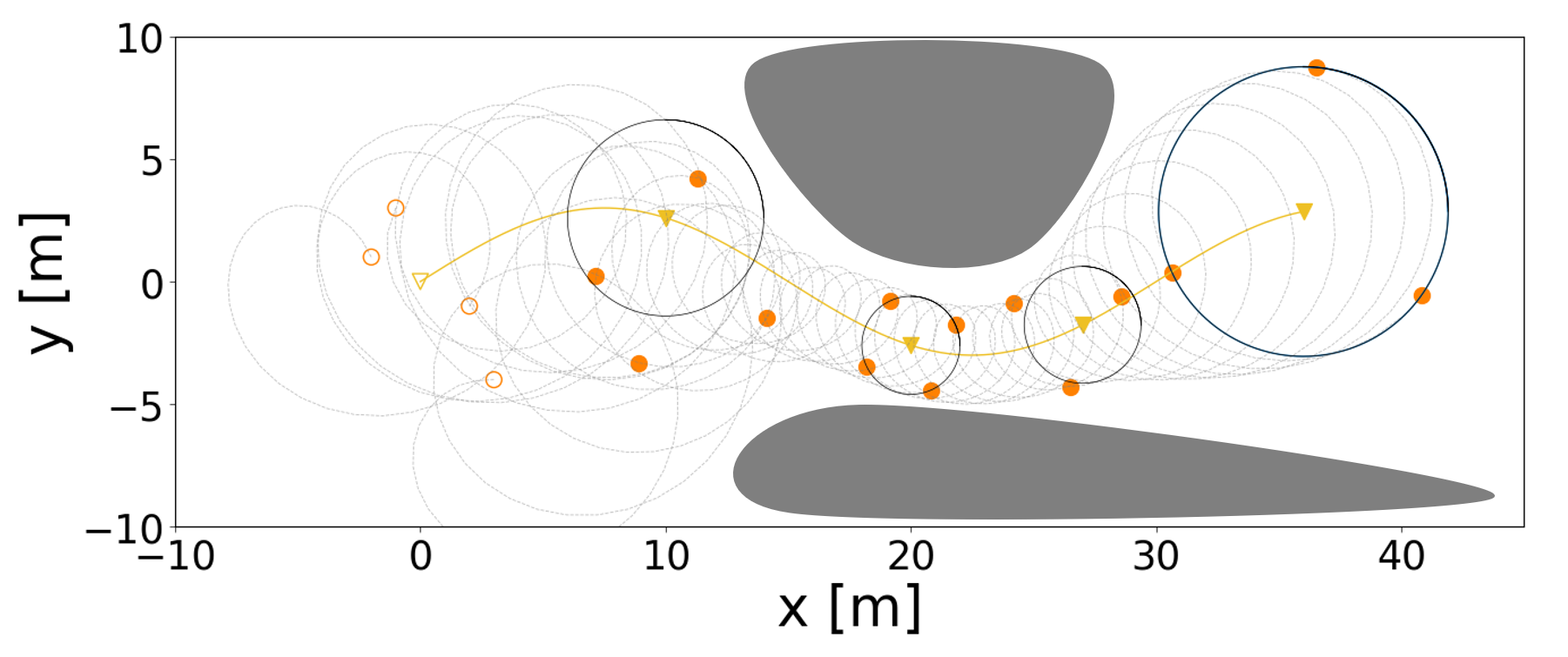
The formation pattern should be dynamically adjusted to effectively deal with complex environments or varied situations during target tracking. For example, it might need to pass through a narrow area in a dynamic narrowing manner (see Fig. 2). Hence, three affine transformations (translation, scaling, and shearing) are used to achieve this object. Simply define the homogeneous coordinates of a vector 𝒒2𝒒superscript2\boldsymbol{q}\in\mathbb{R}^{2} as 𝒒h=(x,y,1)T3superscript𝒒superscript𝑥𝑦1𝑇superscript3\boldsymbol{q}^{h}=(x,y,1)^{T}\in\mathbb{R}^{3}. The affine transformations, translation, scaling, and shearing are respectively defined by the following matrices

𝐓=[10Tx01Ty001],𝐒=[Sx000Sy0001],𝐇=[1Ha0Hb10001]formulae-sequence𝐓delimited-[]10subscript𝑇𝑥01subscript𝑇𝑦001formulae-sequence𝐒delimited-[]subscript𝑆𝑥000subscript𝑆𝑦0001𝐇delimited-[]1subscript𝐻𝑎0subscript𝐻𝑏10001\begin{split}&\mathbf{T}=\left[\begin{array}[]{ccc}1&0&T_{x}\\ 0&1&T_{y}\\ 0&0&1\\ \end{array}\right],\mathbf{S}=\left[\begin{array}[]{ccc}S_{x}&0&0\\ 0&S_{y}&0\\ 0&0&1\\ \end{array}\right],\\ &\mathbf{H}=\left[\begin{array}[]{ccc}1&H_{a}&0\\ H_{b}&1&0\\ 0&0&1\\ \end{array}\right]\end{split}

where Txsubscript𝑇𝑥T_{x}, Tysubscript𝑇𝑦T_{y}, Sxsubscript𝑆𝑥S_{x}, Sysubscript𝑆𝑦S_{y}, Hasubscript𝐻𝑎H_{a}, and Hbsubscript𝐻𝑏H_{b} are external parameters, and Sx,Sy>0subscript𝑆𝑥subscript𝑆𝑦0S_{x},S_{y}>0. The translation items will make the tracking target out of the formation geometry center and can be expressed in a matrix multiplication of the form 𝒒=𝐓𝒒hsuperscript𝒒𝐓superscript𝒒\boldsymbol{q}^{{}^{\prime}}=\mathbf{T}\boldsymbol{q}^{h} where 𝒒superscript𝒒\boldsymbol{q}^{{}^{\prime}} is expressed in homogeneous coordinates. Similarly, scaling and shearing transformation of formation can be reached by 𝒒=𝐒𝒒hsuperscript𝒒𝐒superscript𝒒\boldsymbol{q}^{{}^{\prime}}=\mathbf{S}\boldsymbol{q}^{h}, and 𝒒=𝐇𝒒hsuperscript𝒒𝐇superscript𝒒\boldsymbol{q}^{{}^{\prime}}=\mathbf{H}\boldsymbol{q}^{h} respectively. A scaled circle or ellipse can be obtained by adjusting the parameters. Moreover, based on the formation pattern formed by the coupled oscillator, dynamic additions and subtractions of UAVs will be allowed. As shown in Fig. 2, UAVs will coordinate their relative positions until an equilibrium is restored. It is very suitable for the failure of a UAV during a task.
Refer to caption
Figure 2: Simulation of four UAVs (circles) tracking a moving target (triangle) and passing through narrow areas. The initial positions are represented in void style. The radius of time-varying formation is adjusted by affine transformation. At time step k=250𝑘250k=250, UAV i=4𝑖4i=4 is presumed damaged, and the remaining UAVs can still reach a balanced pattern.

IV Relative localization and tracking control

In this section, a relative localization algorithm is proposed to approximate the relative position between two UAVs or UAV and the moving target. A time-varying formation tracking control algorithm is thereafter developed.

IV-A Relative Localization Estimator

An online localization algorithm is introduced to estimate the relative position between (i,j)¯𝑖𝑗¯(i,j)\in\mathcal{\bar{E}}. The localization algorithm is based on the well-known Recursive Least Square Estimation (RLSE) technique with a forgetting factor. More details on RLSE can be found in [24, 25]. Based on (2), the estimate 𝒑^ij(k)subscriptbold-^𝒑𝑖𝑗𝑘\boldsymbol{\hat{p}}_{ij}(k) is obtained by minimizing the following cost function.

Jij(k)=12l=1kβf[ζij(k)𝒗ijT(l)(𝒑^ij(k)q=lk𝒗ij(q))]2subscript𝐽𝑖𝑗𝑘12superscriptsubscript𝑙1𝑘subscript𝛽𝑓superscriptdelimited-[]subscript𝜁𝑖𝑗𝑘superscriptsubscript𝒗𝑖𝑗𝑇𝑙subscriptbold-^𝒑𝑖𝑗𝑘superscriptsubscript𝑞𝑙𝑘subscript𝒗𝑖𝑗𝑞2\displaystyle J_{ij}(k)=\frac{1}{2}\sum_{l=1}^{k}\beta_{f}\left[\zeta_{ij}(k)-\boldsymbol{v}_{ij}^{T}(l)\left(\boldsymbol{\hat{p}}_{ij}(k)-\sum_{q=l}^{k}\boldsymbol{v}_{ij}(q)\right)\right]^{2} (9)
+12βf[𝒑^ij(k)q=1k𝒗ij(q)𝒑^ij(0)]TΓij1(0)12subscript𝛽𝑓superscriptdelimited-[]subscriptbold-^𝒑𝑖𝑗𝑘superscriptsubscript𝑞1𝑘subscript𝒗𝑖𝑗𝑞subscriptbold-^𝒑𝑖𝑗0𝑇superscriptsubscriptΓ𝑖𝑗10\displaystyle+\frac{1}{2}\beta_{f}\left[\boldsymbol{\hat{p}}_{ij}(k)-\sum_{q=1}^{k}\boldsymbol{v}_{ij}(q)-\boldsymbol{\hat{p}}_{ij}(0)\right]^{T}\varGamma_{ij}^{-1}(0)
[𝒑^ij(k)q=1k𝒗ij(q)𝒑^ij(0)]delimited-[]subscriptbold-^𝒑𝑖𝑗𝑘superscriptsubscript𝑞1𝑘subscript𝒗𝑖𝑗𝑞subscriptbold-^𝒑𝑖𝑗0\displaystyle\left[\boldsymbol{\hat{p}}_{ij}(k)-\sum_{q=1}^{k}\boldsymbol{v}_{ij}(q)-\boldsymbol{\hat{p}}_{ij}(0)\right]

where 𝒑^ij(0)subscriptbold-^𝒑𝑖𝑗0\boldsymbol{\hat{p}}_{ij}(0) is the initial value of 𝒑^ij(k)subscriptbold-^𝒑𝑖𝑗𝑘\boldsymbol{\hat{p}}_{ij}(k), Γij(k)m×msubscriptΓ𝑖𝑗𝑘superscript𝑚𝑚\varGamma_{ij}(k)\in\mathbb{R}^{m\times m} with Γij(0)subscriptΓ𝑖𝑗0\varGamma_{ij}(0) is a positive definite matrix, and βf<1subscript𝛽𝑓1\beta_{f}<1 is a positive constant as forgetting factor. By solving Jij(k)/𝒑^ij(k)=0subscript𝐽𝑖𝑗𝑘subscriptbold-^𝒑𝑖𝑗𝑘0\partial J_{ij}(k)/\partial\boldsymbol{\hat{p}}_{ij}(k)=0, the least-square estimator is given as follows [24]

{ϵij(k)ζij(k)𝒗ijT(k)𝒑^ij(k)Γij(k+)=1βf[Γij(k)Γij(k)𝒗ij(k)𝒗ijT(k)Γij(k)βf+𝒗ijT(k)Γij(k)𝒗ij(k)]𝒑^ij(k+)=𝒑^ij(k)+𝒗ij(k)+Γij(k+)𝒗ij(k)ϵij(k)\left\{\begin{aligned} &\epsilon_{ij}(k)\triangleq\zeta_{ij}(k)-\boldsymbol{v}_{ij}^{T}(k)\boldsymbol{\hat{p}}_{ij}(k)\\ &\varGamma_{ij}(k^{+})=\frac{1}{\beta_{f}}\left[\varGamma_{ij}(k)-\frac{\varGamma_{ij}(k)\boldsymbol{v}_{ij}(k)\boldsymbol{v}_{ij}^{T}(k)\varGamma_{ij}(k)}{\beta_{f}+\boldsymbol{v}_{ij}^{T}(k)\varGamma_{ij}(k)\boldsymbol{v}_{ij}(k)}\right]\\ &\boldsymbol{\hat{p}}_{ij}(k^{+})=\boldsymbol{\hat{p}}_{ij}(k)+\boldsymbol{v}_{ij}(k)+\varGamma_{ij}(k^{+})\boldsymbol{v}_{ij}(k)\epsilon_{ij}(k)\end{aligned}\right. (10)
Remark.

To ensure the exponential convergence of the relative localization estimator, the relative displacement 𝒗ij(k)subscript𝒗𝑖𝑗𝑘\boldsymbol{v}_{ij}(k) should satisfy the persistent excitation condition. A further discussion of convergence is proposed in Section V.

IV-B Formation Tracking Controller

Based on the desired circular formation pattern and the relative position estimates, the cooperative tracking control law as follows

{𝒖¯i(k)βj𝒱¯a¯ij(𝒑^ij(k)𝒓ij(k)),β<1T𝒖i(k)=πU¯i(𝒖¯i(k))+1TΔ𝒓i(k)+𝒖0(k),i𝒱\left\{\begin{aligned} &\boldsymbol{\bar{u}}_{i}(k)\triangleq-\beta\sum_{j\in\mathcal{\bar{V}}}\bar{a}_{ij}\left({\hat{\boldsymbol{p}}}_{ij}(k)-\boldsymbol{r}_{ij}(k)\right),\beta<\frac{1}{T}\\ &\boldsymbol{u}_{i}(k)=\pi_{\bar{U}_{i}}\left(\boldsymbol{\bar{u}}_{i}(k)\right)+\frac{1}{T}\Delta\boldsymbol{r}_{i}(k)+\boldsymbol{u}_{0}(k),i\in\mathcal{V}\end{aligned}\right. (11)

where πU(𝒖)𝒖U/max{U,𝒖}subscript𝜋𝑈𝒖𝒖𝑈𝑈norm𝒖\pi_{U}\left(\boldsymbol{u}\right)\triangleq\boldsymbol{u}U/\max\{U,\|\boldsymbol{u}\|\}, U¯i(0,Ui)subscript¯𝑈𝑖0subscript𝑈𝑖\bar{U}_{i}\in(0,U_{i}) is the upper bound of consensus control term for formation.

Remark.

Note that in (11), and under Assumption 1 that UAV isuperscript𝑖i^{*} can sensing the target, the term 𝒓i0(k)=𝒓i(k)subscript𝒓superscript𝑖0𝑘subscript𝒓superscript𝑖𝑘\boldsymbol{r}_{i^{*}0}(k)=\boldsymbol{r}_{i^{*}}(k) drives formation center to track target. Moreover, 𝒑^i0(k)subscript^𝒑superscript𝑖0𝑘\hat{\boldsymbol{p}}_{i^{*}0}(k) can be replaced by the result of other relative positioning methods, which depends on the scenario and onboard sensor configuration. The term Δ𝒓i(k)Δsubscript𝒓𝑖𝑘\Delta\boldsymbol{r}_{i}(k) in (11) is defined by a future desired setpoint, thus it can be considered as a feedforward term. In addition, it can be seen that Δ𝒓i(k)Δsubscript𝒓𝑖𝑘\Delta\boldsymbol{r}_{i}(k) , which is differentiation, and 𝒖¯i(k)subscriptbold-¯𝒖𝑖𝑘\boldsymbol{\bar{u}}_{i}(k), which only involves relative terms. Thus, our tracking control scheme is independent of the common coordinate frame wsubscript𝑤\mathcal{F}_{w}.

V convergence analysis

V-A Convergence of Relative Localization Error

Given Lemma 1, to simplify our analysis, we assume that after time koTsubscript𝑘𝑜𝑇k_{o}T the coupled oscillator is in equilibrium, thus Δθij(k)θi(k)θj(k)=2πm/nΔsubscript𝜃𝑖𝑗𝑘subscript𝜃𝑖𝑘subscript𝜃𝑗𝑘2𝜋𝑚𝑛\Delta\theta_{ij}(k)\triangleq\theta_{i}(k)-\theta_{j}(k)=2\pi m/n are constants, where k>ko,i,j𝒱,m={1,2,,n1}formulae-sequence𝑘subscript𝑘𝑜𝑖formulae-sequence𝑗𝒱𝑚12𝑛1k>k_{o},i,j\in\mathcal{V},m=\{1,2,...,n-1\}. Therefore, the formation is in uniform circular motion relative to the center of the circle with a period N=2π/Tωi𝑁2𝜋𝑇subscript𝜔𝑖N=\left\lfloor 2\pi/T\omega_{i}\right\rfloor. Further, it is easy to see that a series relative position Wij,l[Δ𝒓ij(l),Δ𝒓ij(l+1),,Δ𝒓ij(l+N1)],l>koformulae-sequencesubscript𝑊𝑖𝑗𝑙Δsubscript𝒓𝑖𝑗𝑙Δsubscript𝒓𝑖𝑗𝑙1Δsubscript𝒓𝑖𝑗𝑙𝑁1for-all𝑙subscript𝑘𝑜W_{ij,l}\triangleq\left[\Delta\boldsymbol{r}_{ij}(l),\Delta\boldsymbol{r}_{ij}(l+1),...,\Delta\boldsymbol{r}_{ij}(l+N-1)\right],\forall l>k_{o} distributed in a circle. Considering real physical systems, assume that ωisubscript𝜔𝑖\omega_{i} is bounded. Hence, a ωisubscript𝜔𝑖\omega_{i} can be easily designed, such that any two vectors in Wij,lsubscript𝑊𝑖𝑗𝑙W_{ij,l} are not equal. In other words, the vectors in Wij,lsubscript𝑊𝑖𝑗𝑙W_{ij,l} are not col-linear, which is formally stated as follows:

Assumption 3.

For any (i,j)¯𝑖𝑗¯(i,j)\in\mathcal{\bar{E}}, there exist ωi<Ωsubscript𝜔𝑖Ω\omega_{i}<\Omega, kosubscript𝑘𝑜k_{o}\in\mathbb{N} and k1,k2{l,l+1,,l+N1}subscript𝑘1subscript𝑘2𝑙𝑙1𝑙𝑁1k_{1},k_{2}\in\{l,l+1,...,l+N-1\}, such that rankWij=2,l>koformulae-sequence𝑟𝑎𝑛𝑘superscriptsubscript𝑊𝑖𝑗2for-all𝑙subscript𝑘𝑜rankW_{ij}^{*}=2,\forall l>k_{o}, where Wij[Δ𝒓ij(k1),Δ𝒓ij(k2)]superscriptsubscript𝑊𝑖𝑗Δsubscript𝒓𝑖𝑗subscript𝑘1Δsubscript𝒓𝑖𝑗subscript𝑘2W_{ij}^{*}\triangleq\left[\Delta\boldsymbol{r}_{ij}(k_{1}),\Delta\boldsymbol{r}_{ij}(k_{2})\right], N=2π/Tωi𝑁2𝜋𝑇subscript𝜔𝑖N=\left\lfloor 2\pi/T\omega_{i}\right\rfloor and ΩΩ\Omega is a positive constant.

Based on the above assumptions, it can be seen that

Δ𝒓ij(k)2ρsin(Tωi/2)TρΩdelimited-∥∥Δsubscript𝒓𝑖𝑗𝑘2𝜌norm𝑇subscript𝜔𝑖2𝑇𝜌Ω\left\lVert\Delta\boldsymbol{r}_{ij}(k)\right\rVert\leq 2\rho\|\sin(T\omega_{i}/2)\|\leq T\rho\Omega (12)

Further, denote λmin(Wij)subscript𝜆𝑚𝑖𝑛superscriptsubscript𝑊𝑖𝑗\lambda_{min}(W_{ij}^{*}) and λmax(Wij)subscript𝜆𝑚𝑎𝑥superscriptsubscript𝑊𝑖𝑗\lambda_{max}(W_{ij}^{*}) as the minimum and the maximum singular values of Wijsuperscriptsubscript𝑊𝑖𝑗W_{ij}^{*}, respectively. Then we can select the sampling time T𝑇T that is sufficiently small

T<g(W)22U¯i𝑇𝑔superscript𝑊22subscript¯𝑈𝑖T<\frac{g(W^{*})}{2\sqrt{2}\bar{U}_{i}} (13)

where g(Wij)=λmax(Wij)λmax2(Wij)λmin2(Wij)𝑔superscriptsubscript𝑊𝑖𝑗subscript𝜆𝑚𝑎𝑥superscriptsubscript𝑊𝑖𝑗superscriptsubscript𝜆𝑚𝑎𝑥2superscriptsubscript𝑊𝑖𝑗superscriptsubscript𝜆𝑚𝑖𝑛2superscriptsubscript𝑊𝑖𝑗g(W_{ij}^{*})=\lambda_{max}(W_{ij}^{*})-\sqrt{\lambda_{max}^{2}(W_{ij}^{*})-\lambda_{min}^{2}(W_{ij}^{*})}, and W=argmaxWij𝒲g(Wij)superscript𝑊subscriptsuperscriptsubscript𝑊𝑖𝑗𝒲𝑔superscriptsubscript𝑊𝑖𝑗W^{*}=\arg\max_{W_{ij}^{*}\in\mathcal{W}}g(W_{ij}^{*}) with𝒲={Wij,lko,(i,j)¯}\mathcal{W}=\{W_{ij}^{*},\forall l\geqslant k_{o},\forall(i,j)\in\mathcal{\bar{E}}\}. Based on Assumption 3 and condition (13), the following theorem is reached.

Theorem 1.

Suppose Assumption 3 holds. Under condition (13), for any (i,j)¯𝑖𝑗¯\left(i,j\right)\in\mathcal{\bar{E}}, there exist αij,2αij,1>0subscript𝛼𝑖𝑗2subscript𝛼𝑖𝑗10\alpha_{ij,2}\geq\alpha_{ij,1}>0, for all lko𝑙subscript𝑘𝑜l\geq k_{o} such that 𝒗ij(k)subscript𝒗𝑖𝑗𝑘\boldsymbol{v}_{ij}(k) satisfy the persistent excitation condition as follows

αij,1I𝚽ij(l)k=ll+N1𝒗ij(k)𝒗ijT(k)αij,2Isubscript𝛼𝑖𝑗1𝐼subscript𝚽𝑖𝑗𝑙superscriptsubscript𝑘𝑙𝑙𝑁1subscript𝒗𝑖𝑗𝑘superscriptsubscript𝒗𝑖𝑗𝑇𝑘subscript𝛼𝑖𝑗2𝐼\alpha_{ij,1}I\leqslant\boldsymbol{\Phi}_{ij}\left(l\right)\triangleq\sum_{k=l}^{l+N-1}{\boldsymbol{v}_{ij}\left(k\right)\boldsymbol{v}_{ij}^{T}\left(k\right)}\leqslant\alpha_{ij,2}I (14)

As a consequence, the relative position error 𝒑~ij(k)subscriptbold-~𝒑𝑖𝑗𝑘\boldsymbol{\tilde{p}}_{ij}(k) converge to 00 exponentially under the least-square estimator (10).

Proof.

It is obvious that 𝚽ij(l)k=ll+N1𝒗ij(k)𝒗ijT(k)subscript𝚽𝑖𝑗𝑙superscriptsubscript𝑘𝑙𝑙𝑁1subscript𝒗𝑖𝑗𝑘superscriptsubscript𝒗𝑖𝑗𝑇𝑘\boldsymbol{\Phi}_{ij}\left(l\right)\triangleq\sum_{k=l}^{l+N-1}{\boldsymbol{v}_{ij}\left(k\right)\boldsymbol{v}_{ij}^{T}\left(k\right)} is a summation of 𝒗ij(k)𝒗ijT(k)subscript𝒗𝑖𝑗𝑘superscriptsubscript𝒗𝑖𝑗𝑇𝑘\boldsymbol{v}_{ij}\left(k\right)\boldsymbol{v}_{ij}^{T}\left(k\right) during a period N𝑁N. Given (i,j)¯𝑖𝑗¯\left(i,j\right)\in\mathcal{\bar{E}}, one has 𝝅ij(k)πU¯i(𝒖¯i(k))πU¯j(𝒖¯j(k))subscript𝝅𝑖𝑗𝑘subscript𝜋subscript¯𝑈𝑖subscriptbold-¯𝒖𝑖𝑘subscript𝜋subscript¯𝑈𝑗subscriptbold-¯𝒖𝑗𝑘\boldsymbol{\pi}_{ij}\left(k\right)\triangleq\pi_{\bar{U}_{i}}\left(\boldsymbol{\bar{u}}_{i}\left(k\right)\right)-\pi_{\bar{U}_{j}}\left(\boldsymbol{\bar{u}}_{j}\left(k\right)\right), and 𝝅i0(k)πU¯i(𝒖¯i(k))subscript𝝅𝑖0𝑘subscript𝜋subscript¯𝑈𝑖subscriptbold-¯𝒖𝑖𝑘\boldsymbol{\pi}_{i0}\left(k\right)\triangleq\pi_{\bar{U}_{i}}\left(\boldsymbol{\bar{u}}_{i}\left(k\right)\right) if j=0𝑗0j=0. It can be obtain from (1),(11) that

𝒗ij(k)=Δ𝒓ij(k)+T𝝅ij(k)subscript𝒗𝑖𝑗𝑘Δsubscript𝒓𝑖𝑗𝑘𝑇subscript𝝅𝑖𝑗𝑘\boldsymbol{v}_{ij}\left(k\right)=\Delta\boldsymbol{r}_{ij}\left(k\right)+T\boldsymbol{\pi}_{ij}(k)

Considering that every term of the formation control law is bounded, and recalling Assumption 2 it is easy to see

𝝅ij(k)2U¯idelimited-∥∥subscript𝝅𝑖𝑗𝑘2subscript¯𝑈𝑖\left\lVert\boldsymbol{\pi}_{ij}\left(k\right)\right\rVert\leq 2\bar{U}_{i}

Since l𝑙l can be regarded as the initial moment of the iteration, it incurs no loss of generality to only show (14) for𝚽ij(1)subscript𝚽𝑖𝑗1\boldsymbol{\Phi}_{ij}(1). To show αij,1I𝚽ij(1)αij,2Isubscript𝛼𝑖𝑗1𝐼subscript𝚽𝑖𝑗1subscript𝛼𝑖𝑗2𝐼\alpha_{ij,1}I\leqslant\boldsymbol{\Phi}_{ij}\left(1\right)\leqslant\alpha_{ij,2}I, it is equivalent to show that for any unit vector 𝒙𝒙\boldsymbol{x},

αij,1𝒙T𝚽ij(1)𝒙αij,2subscript𝛼𝑖𝑗1superscript𝒙𝑇subscript𝚽𝑖𝑗1𝒙subscript𝛼𝑖𝑗2\alpha_{ij,1}\leqslant\boldsymbol{x}^{T}\boldsymbol{\Phi}_{ij}\left(1\right)\boldsymbol{x}\leqslant\alpha_{ij,2}

Denote

Wij=[Δ𝒓ij(1),Δ𝒓ij(2),,Δ𝒓ij(N)]subscript𝑊𝑖𝑗Δsubscript𝒓𝑖𝑗1Δsubscript𝒓𝑖𝑗2Δsubscript𝒓𝑖𝑗𝑁W_{ij}=\left[\Delta\boldsymbol{r}_{ij}(1),\Delta\boldsymbol{r}_{ij}(2),...,\Delta\boldsymbol{r}_{ij}(N)\right]
Vij=[𝝅ij(1),𝝅ij(2),,𝝅ij(N)]subscript𝑉𝑖𝑗subscript𝝅𝑖𝑗1subscript𝝅𝑖𝑗2subscript𝝅𝑖𝑗𝑁V_{ij}=\left[\boldsymbol{\pi}_{ij}(1),\boldsymbol{\pi}_{ij}(2),...,\boldsymbol{\pi}_{ij}(N)\right]

Direct computation shows that

𝒙T𝚽ij(1)𝒙=WijT2+2TWijT𝒙,VijT𝒙+T2VijT2superscript𝒙𝑇subscript𝚽𝑖𝑗1𝒙superscriptdelimited-∥∥superscriptsubscript𝑊𝑖𝑗𝑇22𝑇superscriptsubscript𝑊𝑖𝑗𝑇𝒙superscriptsubscript𝑉𝑖𝑗𝑇𝒙superscript𝑇2superscriptdelimited-∥∥superscriptsubscript𝑉𝑖𝑗𝑇2\boldsymbol{x}^{T}\boldsymbol{\Phi}_{ij}(1)\boldsymbol{x}=\left\lVert W_{ij}^{T}\right\rVert^{2}+2T\left\langle W_{ij}^{T}\boldsymbol{x},V_{ij}^{T}\boldsymbol{x}\right\rangle+T^{2}\left\lVert V_{ij}^{T}\right\rVert^{2}

By applying Cauchy-Swartz inequality, there is

WijT𝒙VijT𝒙WijT𝒙,VijT𝒙WijT𝒙VijT𝒙delimited-∥∥superscriptsubscript𝑊𝑖𝑗𝑇𝒙delimited-∥∥superscriptsubscript𝑉𝑖𝑗𝑇𝒙superscriptsubscript𝑊𝑖𝑗𝑇𝒙superscriptsubscript𝑉𝑖𝑗𝑇𝒙delimited-∥∥superscriptsubscript𝑊𝑖𝑗𝑇𝒙delimited-∥∥superscriptsubscript𝑉𝑖𝑗𝑇𝒙-\left\lVert W_{ij}^{T}\boldsymbol{x}\right\rVert\left\lVert V_{ij}^{T}\boldsymbol{x}\right\rVert\leq\left\langle W_{ij}^{T}\boldsymbol{x},V_{ij}^{T}\boldsymbol{x}\right\rangle\leq\left\lVert W_{ij}^{T}\boldsymbol{x}\right\rVert\left\lVert V_{ij}^{T}\boldsymbol{x}\right\rVert

Below we will separately show both sides of αij,1𝒙T𝚽ij(1)𝒙αij,2subscript𝛼𝑖𝑗1superscript𝒙𝑇subscript𝚽𝑖𝑗1𝒙subscript𝛼𝑖𝑗2\alpha_{ij,1}\leqslant\boldsymbol{x}^{T}\boldsymbol{\Phi}_{ij}\left(1\right)\boldsymbol{x}\leqslant\alpha_{ij,2}.

  1. 1.

    Equivalently, we will show that there exists αij,2>0subscript𝛼𝑖𝑗20\alpha_{ij,2}>0 such that 𝒙T𝚽ij(1)𝒙αij,2superscript𝒙𝑇subscript𝚽𝑖𝑗1𝒙subscript𝛼𝑖𝑗2\boldsymbol{x}^{T}\boldsymbol{\Phi}_{ij}\left(1\right)\boldsymbol{x}\leqslant\alpha_{ij,2} for any unit vector 𝒙𝒙\boldsymbol{x}.

    𝒙T𝚽ij(1)𝒙superscript𝒙𝑇subscript𝚽𝑖𝑗1𝒙\displaystyle\boldsymbol{x}^{T}\boldsymbol{\Phi}_{ij}\left(1\right)\boldsymbol{x}
    WijT𝒙2+2TWijT𝒙VijT𝒙+T2VijT𝒙2absentsuperscriptdelimited-∥∥superscriptsubscript𝑊𝑖𝑗𝑇𝒙22𝑇delimited-∥∥superscriptsubscript𝑊𝑖𝑗𝑇𝒙delimited-∥∥superscriptsubscript𝑉𝑖𝑗𝑇𝒙superscript𝑇2superscriptdelimited-∥∥superscriptsubscript𝑉𝑖𝑗𝑇𝒙2\displaystyle\leq\left\lVert W_{ij}^{T}\boldsymbol{x}\right\rVert^{2}+2T\left\lVert W_{ij}^{T}\boldsymbol{x}\right\rVert\left\lVert V_{ij}^{T}\boldsymbol{x}\right\rVert+T^{2}\left\lVert V_{ij}^{T}\boldsymbol{x}\right\rVert^{2}
    (WijT𝒙+TVijTx)2absentsuperscriptdelimited-∥∥superscriptsubscript𝑊𝑖𝑗𝑇𝒙𝑇delimited-∥∥superscriptsubscript𝑉𝑖𝑗𝑇𝑥2\displaystyle\leq\left(\left\lVert W_{ij}^{T}\boldsymbol{x}\right\rVert+T\left\lVert V_{ij}^{T}x\right\rVert\right)^{2}
    NT2(𝝆Ω+2U¯i)2αij,2absent𝑁superscript𝑇2superscript𝝆Ω2subscript¯𝑈𝑖2subscript𝛼𝑖𝑗2\displaystyle\leq NT^{2}\left(\boldsymbol{\rho}\Omega+2\bar{U}_{i}\right)^{2}\triangleq\alpha_{ij,2}

    by recalling (12). Thus 𝚽ij(1)αij,2Isubscript𝚽𝑖𝑗1subscript𝛼𝑖𝑗2𝐼\boldsymbol{\Phi}_{ij}\left(1\right)\leqslant\alpha_{ij,2}I.

  2. 2.

    Equivalently, we will show that there exists αij,1>0subscript𝛼𝑖𝑗10\alpha_{ij,1}>0 such that 𝒙T𝚽ij(1)𝒙αij,1superscript𝒙𝑇subscript𝚽𝑖𝑗1𝒙subscript𝛼𝑖𝑗1\boldsymbol{x}^{T}\boldsymbol{\Phi}_{ij}\left(1\right)\boldsymbol{x}\geq\alpha_{ij,1} for any unit vector 𝒙𝒙\boldsymbol{x}. By recalling Assumption 3, with Wij[Δ𝒓ij(k1),Δ𝒓ij(k2)],k1,k21,2,,Nformulae-sequencesuperscriptsubscript𝑊𝑖𝑗Δsubscript𝒓𝑖𝑗subscript𝑘1Δsubscript𝒓𝑖𝑗subscript𝑘2subscript𝑘1subscript𝑘212𝑁W_{ij}^{*}\triangleq\left[\Delta\boldsymbol{r}_{ij}(k_{1}),\Delta\boldsymbol{r}_{ij}(k_{2})\right],k_{1},k_{2}\in{1,2,...,N}. We have 𝚽ij(1)k={k1,k2}𝒗ij(k)𝒗ijT(k)𝐒ij(1)subscript𝚽𝑖𝑗1subscript𝑘subscript𝑘1subscript𝑘2subscript𝒗𝑖𝑗𝑘superscriptsubscript𝒗𝑖𝑗𝑇𝑘subscript𝐒𝑖𝑗1\boldsymbol{\Phi}_{ij}\left(1\right)\geq\sum_{k=\{k_{1},k_{2}\}}\boldsymbol{v}_{ij}\left(k\right)\boldsymbol{v}_{ij}^{T}\left(k\right)\triangleq\mathbf{S}_{ij}(1).

    Similar to the preceding, direct computation shows that

    𝒙T𝚽ij(1)𝒙𝒙T𝐒ij(1)𝒙superscript𝒙𝑇subscript𝚽𝑖𝑗1𝒙superscript𝒙𝑇subscript𝐒𝑖𝑗1𝒙\displaystyle\boldsymbol{x}^{T}\boldsymbol{\Phi}_{ij}\left(1\right)\boldsymbol{x}\geq\boldsymbol{x}^{T}\mathbf{S}_{ij}\left(1\right)\boldsymbol{x}
    WijT𝒙22TWijT𝒙VijT𝒙+T2VijT2absentsuperscriptdelimited-∥∥superscriptsuperscriptsubscript𝑊𝑖𝑗𝑇𝒙22𝑇delimited-∥∥superscriptsuperscriptsubscript𝑊𝑖𝑗𝑇𝒙delimited-∥∥superscriptsuperscriptsubscript𝑉𝑖𝑗𝑇𝒙superscript𝑇2superscriptdelimited-∥∥superscriptsuperscriptsubscript𝑉𝑖𝑗𝑇2\displaystyle\geq\left\lVert{W_{ij}^{*}}^{T}\boldsymbol{x}\right\rVert^{2}-2T\left\lVert{W_{ij}^{*}}^{T}\boldsymbol{x}\right\rVert\left\lVert{V_{ij}^{*}}^{T}\boldsymbol{x}\right\rVert+T^{2}\left\lVert{V_{ij}^{*}}^{T}\right\rVert^{2}
    λmin22Tλmax2VijT𝒙+T2VijT2absentsuperscriptsubscript𝜆𝑚𝑖𝑛22𝑇superscriptsubscript𝜆𝑚𝑎𝑥2delimited-∥∥superscriptsuperscriptsubscript𝑉𝑖𝑗𝑇𝒙superscript𝑇2superscriptdelimited-∥∥superscriptsuperscriptsubscript𝑉𝑖𝑗𝑇2\displaystyle\geq\lambda_{min}^{2}-2T\lambda_{max}^{2}\left\lVert{V_{ij}^{*}}^{T}\boldsymbol{x}\right\rVert+T^{2}\left\lVert{V_{ij}^{*}}^{T}\right\rVert^{2}

    where 0<λminλmax0subscript𝜆𝑚𝑖𝑛subscript𝜆𝑚𝑎𝑥0<\lambda_{min}\leq\lambda_{max} are respectively the smallest and the largest singular values of Wijsuperscriptsubscript𝑊𝑖𝑗W_{ij}^{*}, and Vij[𝝅ij(k1),𝝅ij(k2)]superscriptsubscript𝑉𝑖𝑗subscript𝝅𝑖𝑗subscript𝑘1subscript𝝅𝑖𝑗subscript𝑘2V_{ij}^{*}\triangleq\left[\boldsymbol{\pi}_{ij}(k_{1}),\boldsymbol{\pi}_{ij}(k_{2})\right]. Noticed that Vij22U¯idelimited-∥∥superscriptsubscript𝑉𝑖𝑗22subscript¯𝑈𝑖\left\lVert{V_{ij}^{*}}\right\rVert\leq 2\sqrt{2}\bar{U}_{i}, we can see that if αij,1<λmin2subscript𝛼𝑖𝑗1superscriptsubscript𝜆𝑚𝑖𝑛2\alpha_{ij,1}<\lambda_{min}^{2}, then the above can be achieved with 22TU¯iλmaxλmax2λmin222𝑇subscript¯𝑈𝑖subscript𝜆𝑚𝑎𝑥superscriptsubscript𝜆𝑚𝑎𝑥2superscriptsubscript𝜆𝑚𝑖𝑛22\sqrt{2}T\bar{U}_{i}\leq\lambda_{max}-\sqrt{\lambda_{max}^{2}-\lambda_{min}^{2}}. Taken Wij=Wsuperscriptsubscript𝑊𝑖𝑗superscript𝑊W_{ij}^{*}=W^{*} in (13) , we have shown that 𝚽ij(1)αij,1Isubscript𝚽𝑖𝑗1subscript𝛼𝑖𝑗1𝐼\boldsymbol{\Phi}_{ij}\left(1\right)\geq\alpha_{ij,1}I

By combing 1) and 2) the persistent excitation condition of 𝒗ij(k)subscript𝒗𝑖𝑗𝑘\boldsymbol{v}_{ij}(k) can be obtained. After that, to study the convergence of the estimator (10), the similar process as in the Theorem IV.1 of [24]. ∎

Remark.

We should note that it is still possible for 𝒗ij(k)subscript𝒗𝑖𝑗𝑘\boldsymbol{v}_{ij}(k) to satisfy the persistent excitation condition even during the time steps 0<k<ko0𝑘subscript𝑘𝑜0<k<k_{o} while (8) does not converge. This paper only describes the sufficient condition to meet the persistent excitation condition.

V-B Convergence of Formation Tracking Error

Based on Theorem 1, we will show the convergence of formation tracking error 𝒑¯(k)bold-¯𝒑𝑘\boldsymbol{\bar{p}}(k).

Theorem 2.

Let Assumption 1 and 2 hold, and select T𝑇T by the condition (13), then the center of the time-varying formation 𝒑(k)𝒑𝑘\boldsymbol{p}(k) converges to the target’s position 𝒑0(k)subscript𝒑0𝑘\boldsymbol{p}_{0}(k) exponentially fast under the tracking control law (11).

Proof.

To proof limk𝒑¯(k)=0subscript𝑘delimited-∥∥bold-¯𝒑𝑘0\lim_{k\rightarrow\infty}\left\lVert\boldsymbol{\bar{p}}(k)\right\rVert=0 is equal to proof limki𝒱(𝒑i(k)𝒑0(k))=0subscript𝑘delimited-∥∥subscript𝑖𝒱subscript𝒑𝑖𝑘subscript𝒑0𝑘0\lim_{k\rightarrow\infty}\left\lVert\sum_{i\in\mathcal{V}}\left(\boldsymbol{p}_{i}(k)-\boldsymbol{p}_{0}(k)\right)\right\rVert=0. Further, it is equal to the following convergence for any i𝒱𝑖𝒱i\in\mathcal{V}

limksup𝒑¯i(k)=0subscript𝑘supremumdelimited-∥∥subscriptbold-¯𝒑𝑖𝑘0\lim_{k\rightarrow\infty}\sup\left\lVert\boldsymbol{\bar{p}}_{i}(k)\right\rVert=0 (15)

where 𝒑¯i(k)𝒑i(k)𝒓i(k)𝒑0(k)subscriptbold-¯𝒑𝑖𝑘subscript𝒑𝑖𝑘subscript𝒓𝑖𝑘subscript𝒑0𝑘\boldsymbol{\bar{p}}_{i}(k)\triangleq\boldsymbol{p}_{i}(k)-\boldsymbol{r}_{i}(k)-\boldsymbol{p}_{0}(k). By recalling (1) and (11), we can find that

𝒑¯i(k+)subscriptbold-¯𝒑𝑖superscript𝑘\displaystyle\boldsymbol{\bar{p}}_{i}(k^{+}) =𝒑¯i(k)+TπU¯i(𝒖¯i(k))absentsubscriptbold-¯𝒑𝑖𝑘𝑇subscript𝜋subscript¯𝑈𝑖subscriptbold-¯𝒖𝑖𝑘\displaystyle=\boldsymbol{\bar{p}}_{i}(k)+T\pi_{\bar{U}_{i}}\left(\boldsymbol{\bar{u}}_{i}(k)\right) (16)
=γi(k)𝒑¯i(k)+j𝒩iγij(k)𝒑¯j(k)𝒆i(k)absentsubscript𝛾𝑖𝑘subscriptbold-¯𝒑𝑖𝑘subscript𝑗subscript𝒩𝑖subscript𝛾𝑖𝑗𝑘subscriptbold-¯𝒑𝑗𝑘subscript𝒆𝑖𝑘\displaystyle=\gamma_{i}(k)\boldsymbol{\bar{p}}_{i}(k)+\sum_{j\in\mathcal{N}_{i}}\gamma_{ij}(k)\boldsymbol{\bar{p}}_{j}(k)-\boldsymbol{e}_{i}(k)

where γij(k)=Tβsi(k)a¯ijsubscript𝛾𝑖𝑗𝑘𝑇𝛽subscript𝑠𝑖𝑘subscript¯𝑎𝑖𝑗\gamma_{ij}(k)=T\beta s_{i}(k)\bar{a}_{ij}, γi(k)=1j𝒩¯iγij(k)=1Tβsi(k)subscript𝛾𝑖𝑘1subscript𝑗subscript¯𝒩𝑖subscript𝛾𝑖𝑗𝑘1𝑇𝛽subscript𝑠𝑖𝑘\gamma_{i}(k)=1-\sum_{j\in\mathcal{\bar{N}}_{i}}\gamma_{ij}(k)=1-T\beta s_{i}(k), by using 𝚺j𝒩¯ia¯ij=1subscript𝚺𝑗subscript¯𝒩𝑖subscript¯𝑎𝑖𝑗1\boldsymbol{\Sigma}_{j\in\mathcal{\bar{N}}_{i}}\bar{a}_{ij}=1, and si(k)U/max{U,𝒖}(0,1]subscript𝑠𝑖𝑘𝑈𝑈norm𝒖01s_{i}(k)\triangleq U/\max\{U,\|\boldsymbol{u}\|\}\in(0,1], hence γi(k),γij(k)(0,1)subscript𝛾𝑖𝑘subscript𝛾𝑖𝑗𝑘01\gamma_{i}(k),\gamma_{ij}(k)\in(0,1). As the result of Theorem 1, there exist δ>0𝛿0\delta>0 and 0<λ<10𝜆10<\lambda<1 such that 𝒆i(k)δλkdelimited-∥∥subscript𝒆𝑖𝑘𝛿superscript𝜆𝑘\left\lVert\boldsymbol{e}_{i}(k)\right\rVert\leq\delta\lambda^{k} for all i𝒱𝑖𝒱i\in\mathcal{V}. By applying the trangle inequality to (16), we get

𝒑¯i(k+)delimited-∥∥subscriptbold-¯𝒑𝑖superscript𝑘\displaystyle\left\lVert\boldsymbol{\bar{p}}_{i}(k^{+})\right\rVert γi(k)𝒑¯i(k)+j𝒩iγij(k)𝒑¯j(k)+δλkabsentsubscript𝛾𝑖𝑘delimited-∥∥subscriptbold-¯𝒑𝑖𝑘subscript𝑗subscript𝒩𝑖subscript𝛾𝑖𝑗𝑘delimited-∥∥subscriptbold-¯𝒑𝑗𝑘𝛿superscript𝜆𝑘\displaystyle\leq\gamma_{i}(k)\left\lVert\boldsymbol{\bar{p}}_{i}(k)\right\rVert+\sum_{j\in\mathcal{N}_{i}}\gamma_{ij}(k)\left\lVert\boldsymbol{\bar{p}}_{j}(k)\right\rVert+\delta\lambda^{k} (17)

Accordingly, we can rewrite the inequations in matrix form for all i𝒱𝑖𝒱i\in\mathcal{V}. Thus, we get the following componentwise inequality

𝒫(k+1)Λ(k)𝒫(k)+𝟏nδλk𝒫𝑘1Λ𝑘𝒫𝑘subscript1𝑛𝛿superscript𝜆𝑘\mathcal{P}(k+1)\leq\Lambda(k)\mathcal{P}(k)+\mathbf{1}_{n}\delta\lambda^{k} (18)

where 𝒫(k)[𝒑¯1(k),,𝒑¯n(k)]T𝒫𝑘superscriptdelimited-∥∥subscriptbold-¯𝒑1𝑘delimited-∥∥subscriptbold-¯𝒑𝑛𝑘𝑇\mathcal{P}(k)\triangleq\left[\left\lVert\boldsymbol{\bar{p}}_{1}(k)\right\rVert,...,\left\lVert\boldsymbol{\bar{p}}_{n}(k)\right\rVert\right]^{T}, and

Λ(k)[γ1(k)γ12(k)γ1n(k)γ21(k)γ2(k)γ2n(k)γn1(k)γn2(k)γn(k)]Λ𝑘delimited-[]subscript𝛾1𝑘subscript𝛾12𝑘subscript𝛾1𝑛𝑘subscript𝛾21𝑘subscript𝛾2𝑘subscript𝛾2𝑛𝑘subscript𝛾𝑛1𝑘subscript𝛾𝑛2𝑘subscript𝛾𝑛𝑘\Lambda(k)\triangleq\left[\begin{array}[]{cccc}\gamma_{1}(k)&\gamma_{12}(k)&\cdots&\gamma_{1n}(k)\\ \gamma_{21}(k)&\gamma_{2}(k)&\cdots&\gamma_{2n}(k)\\ \vdots&\vdots&\ddots&\vdots\\ \gamma_{n1}(k)&\gamma_{n2}(k)&\cdots&\gamma_{n}(k)\\ \end{array}\right]

Clearly, Λ(k)Λ𝑘\Lambda(k) is a nonnegative matrix with each row sum Λi(k)𝟏nγi(k)+j𝒩iγij(k)=1γi0(k)1subscriptΛ𝑖𝑘subscript1𝑛subscript𝛾𝑖𝑘subscript𝑗subscript𝒩𝑖subscript𝛾𝑖𝑗𝑘1subscript𝛾𝑖0𝑘1\Lambda_{i}(k)\mathbf{1}_{n}\triangleq\gamma_{i}(k)+\sum_{j\in\mathcal{N}_{i}}\gamma_{ij}(k)=1-\gamma_{i0}(k)\leqslant 1. The equality occurs if and only if 0𝒩¯i0subscript¯𝒩𝑖0\notin\mathcal{\bar{N}}_{i}. Thus, Λ(k)𝟏n𝟏nΛ𝑘subscript1𝑛subscript1𝑛\Lambda(k)\mathbf{1}_{n}\leqslant\mathbf{1}_{n}, and we get

𝒫(k)𝒫(k1)+𝟏nδλk1𝒫(0)+𝟏nδt=0k1λl𝒫𝑘𝒫𝑘1subscript1𝑛𝛿superscript𝜆𝑘1𝒫0subscript1𝑛𝛿superscriptsubscript𝑡0𝑘1superscript𝜆𝑙\mathcal{P}(k)\leq\mathcal{P}(k-1)+\mathbf{1}_{n}\delta\lambda^{k-1}\leq\mathcal{P}(0)+\mathbf{1}_{n}\delta\sum_{t=0}^{k-1}\lambda^{l}

which means 𝒑¯i(k)subscriptbold-¯𝒑𝑖𝑘\boldsymbol{\bar{p}}_{i}(k) is bounded. After showing the boundedness of 𝒑¯i(k)subscriptbold-¯𝒑𝑖𝑘\boldsymbol{\bar{p}}_{i}(k), we will establish the convergence based on (18) in the following.

Under Assumption 1, we can classify the UAVs into two groups 𝖮1subscript𝖮1\mathsf{O}_{1} and 𝖮2subscript𝖮2\mathsf{O}_{2}. The shortest path from i𝖮1𝑖subscript𝖮1i\in\mathsf{O}_{1} to the target 00 be of length l=1𝑙1l=1, and l=2𝑙2l=2 for i𝖮2𝑖subscript𝖮2i\in\mathsf{O}_{2}. Denote 𝖰(k)=maxi𝒱𝒑¯i(k)𝖰𝑘subscript𝑖𝒱subscriptbold-¯𝒑𝑖𝑘\mathsf{Q}(k)=\max_{i\in\mathcal{V}}\left\lVert\boldsymbol{\bar{p}}_{i}(k)\right\rVert. We will show that for any i𝖮l,l=1,2formulae-sequence𝑖subscript𝖮𝑙𝑙12i\in\mathsf{O}_{l},l=1,2, there exist ηi(0,1)subscript𝜂𝑖01\eta_{i}\in(0,1) such that

𝒑¯i(k+2)ηi𝖰(k)+δt=kk+1λtdelimited-∥∥subscriptbold-¯𝒑𝑖𝑘2subscript𝜂𝑖𝖰𝑘𝛿superscriptsubscript𝑡𝑘𝑘1superscript𝜆𝑡\left\lVert\boldsymbol{\bar{p}}_{i}(k+2)\right\rVert\leq\eta_{i}\mathsf{Q}(k)+\delta\sum_{t=k}^{k+1}\lambda^{t} (19)

To show (19), we note that (18) implies that

𝒫(k+2)Λ(k+1)Λ(k)𝒫(k)+𝟏nδt=kk+1λt𝒫𝑘2Λ𝑘1Λ𝑘𝒫𝑘subscript1𝑛𝛿superscriptsubscript𝑡𝑘𝑘1superscript𝜆𝑡\mathcal{P}(k+2)\leq\Lambda(k+1)\Lambda(k)\mathcal{P}(k)+\mathbf{1}_{n}\delta\sum_{t=k}^{k+1}\lambda^{t}

For i𝖮1𝑖subscript𝖮1i\in\mathsf{O}_{1}, it is clear that Λi(k)𝟏n=1γi0(k)ηi(k)<1subscriptΛ𝑖𝑘subscript1𝑛1subscript𝛾𝑖0𝑘subscript𝜂𝑖𝑘1\Lambda_{i}(k)\mathbf{1}_{n}=1-\gamma_{i0}(k)\triangleq\eta_{i}(k)<1, where γi0(k)>0subscript𝛾𝑖0𝑘0\gamma_{i0}(k)>0 due to 0𝒩¯i0subscript¯𝒩𝑖0\in\mathcal{\bar{N}}_{i}. Note that Λ(k)𝟏n<κi(k)Λ𝑘subscript1𝑛subscript𝜅𝑖𝑘\Lambda(k)\mathbf{1}_{n}<\kappa_{i}(k), where κi(k)nsubscript𝜅𝑖𝑘superscript𝑛\kappa_{i}(k)\in\mathbb{R}^{n} is obtained by replacing the ithsuperscript𝑖𝑡i^{th} entry of 𝟏nsubscript1𝑛\mathbf{1}_{n} with ηi(k)subscript𝜂𝑖𝑘\eta_{i}(k). Then, we have

Λi(k+1)Λ(k)𝟏nΛi(k+1)κi(k)γi(k+1)ηi(k)+j𝒩iγij(k+1)=ηi(k)γi(k+1)γi0(k+1)ηiηi(k)<1subscriptΛ𝑖𝑘1Λ𝑘subscript1𝑛subscriptΛ𝑖𝑘1subscript𝜅𝑖𝑘subscript𝛾𝑖𝑘1subscript𝜂𝑖𝑘subscript𝑗subscript𝒩𝑖subscript𝛾𝑖𝑗𝑘1subscript𝜂𝑖𝑘subscript𝛾𝑖𝑘1subscript𝛾𝑖0𝑘1subscript𝜂𝑖subscript𝜂𝑖𝑘1\begin{split}\Lambda_{i}(k+1)\Lambda(k)\mathbf{1}_{n}&\leq\Lambda_{i}(k+1)\kappa_{i}(k)\\ &\leq\gamma_{i}(k+1)\eta_{i}(k)+\sum_{j\in\mathcal{N}_{i}}\gamma_{ij}(k+1)\\ &=\eta_{i}(k)-\gamma_{i}(k+1)\gamma_{i0}(k+1)\\ &\triangleq\eta_{i}\leqslant\eta_{i}(k)<1\end{split}

For j𝖮2𝑗subscript𝖮2j\in\mathsf{O}_{2}, which is connected to the above i𝖮1𝑖subscript𝖮1i\in\mathsf{O}_{1}, it follows from Λ(k)𝟏n<κi(k)Λ𝑘subscript1𝑛subscript𝜅𝑖𝑘\Lambda(k)\mathbf{1}_{n}<\kappa_{i}(k) that

Λj(k+1)Λ(k)𝟏nΛj(k+1)κi(k)=Λj(k+1)𝟏nγji(k+1)+γji(k+1)ηi(k)=1γji(k+1)(1ηi(k))ηj<1subscriptΛ𝑗𝑘1Λ𝑘subscript1𝑛subscriptΛ𝑗𝑘1subscript𝜅𝑖𝑘subscriptΛ𝑗𝑘1subscript1𝑛subscript𝛾𝑗𝑖𝑘1subscript𝛾𝑗𝑖𝑘1subscript𝜂𝑖𝑘1subscript𝛾𝑗𝑖𝑘11subscript𝜂𝑖𝑘subscript𝜂𝑗1\begin{split}\Lambda_{j}(k+1)&\Lambda(k)\mathbf{1}_{n}\leq\Lambda_{j}(k+1)\kappa_{i}(k)\\ &=\Lambda_{j}(k+1)\mathbf{1}_{n}-\gamma_{ji}(k+1)+\gamma_{ji}(k+1)\eta_{i}(k)\\ &=1-\gamma_{ji}(k+1)\left(1-\eta_{i}(k)\right)\triangleq\eta_{j}<1\end{split}

Swithching j𝑗j to i𝑖i, and combine the two cases above, we have

𝒑¯i(k+2)Λi(k+1)Λ(k)𝒫(k)+δt=kk+1λtΛi(k+1)Λ(k)𝟏n𝖰(k)+δt=kk+1λtηi𝖰(k)+δt=kk+1λt,i𝒱formulae-sequencedelimited-∥∥subscriptbold-¯𝒑𝑖𝑘2subscriptΛ𝑖𝑘1Λ𝑘𝒫𝑘𝛿superscriptsubscript𝑡𝑘𝑘1superscript𝜆𝑡subscriptΛ𝑖𝑘1Λ𝑘subscript1𝑛𝖰𝑘𝛿superscriptsubscript𝑡𝑘𝑘1superscript𝜆𝑡subscript𝜂𝑖𝖰𝑘𝛿superscriptsubscript𝑡𝑘𝑘1superscript𝜆𝑡for-all𝑖𝒱\begin{split}\left\lVert\boldsymbol{\bar{p}}_{i}(k+2)\right\rVert&\leq\Lambda_{i}(k+1)\Lambda(k)\mathcal{P}(k)+\delta\sum_{t=k}^{k+1}\lambda^{t}\\ &\leq\Lambda_{i}(k+1)\Lambda(k)\mathbf{1}_{n}\mathsf{Q}(k)+\delta\sum_{t=k}^{k+1}\lambda^{t}\\ &\leq\eta_{i}\mathsf{Q}(k)+\delta\sum_{t=k}^{k+1}\lambda^{t},\forall i\in\mathcal{V}\end{split}

Further, by letting η=mini𝒱ηi(0,1)𝜂subscript𝑖𝒱subscript𝜂𝑖01\eta=\min_{i\in\mathcal{V}}\eta_{i}\in(0,1), we can obtain

𝖰(k+2)η𝖰(k)+δt=kk+1λt𝖰𝑘2𝜂𝖰𝑘𝛿superscriptsubscript𝑡𝑘𝑘1superscript𝜆𝑡\mathsf{Q}(k+2)\leq\eta\mathsf{Q}(k)+\delta\sum_{t=k}^{k+1}\lambda^{t} (20)

which implies the exponentially convergent of 𝒑¯isubscriptbold-¯𝒑𝑖\boldsymbol{\bar{p}}_{i}, i.e. the center of the time-varying formation 𝒑(k)𝒑𝑘\boldsymbol{p}(k) converges to the target’s position 𝒑0(k)subscript𝒑0𝑘\boldsymbol{p}_{0}(k) exponentially fast under the tracking control law (11).

Refer to caption
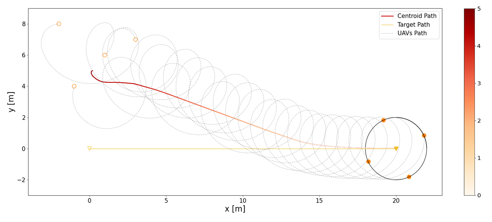
Figure 3: Four UAVs tracking a moving target. The centroid path gradually converges to the target path. The gradient color of the path indicates a gradual reduction in tracking error.
Refer to caption
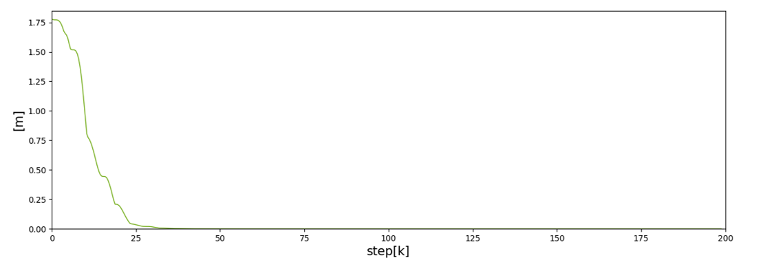
Figure 4: The relative phase of UAVs, denoted by θi(k)kTωisubscript𝜃𝑖𝑘𝑘𝑇subscript𝜔𝑖\theta_{i}(k)-kT\omega_{i}.
Refer to caption
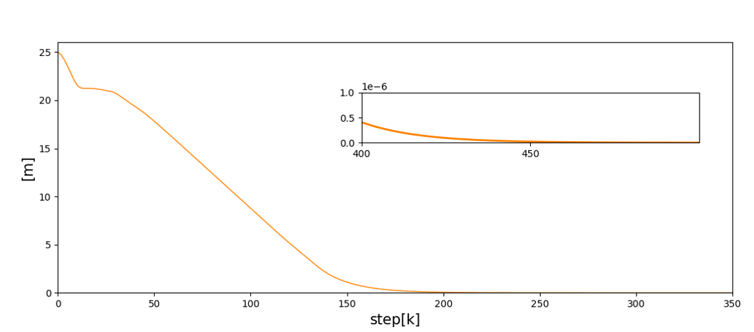
Figure 5: The relative position error max(i,j)¯𝒑~ij(k)subscript𝑖𝑗¯subscriptbold-~𝒑𝑖𝑗𝑘\max_{(i,j)\in\mathcal{\bar{E}}}\left\lVert\boldsymbol{\tilde{p}}_{ij}(k)\right\rVert.

.

Refer to caption
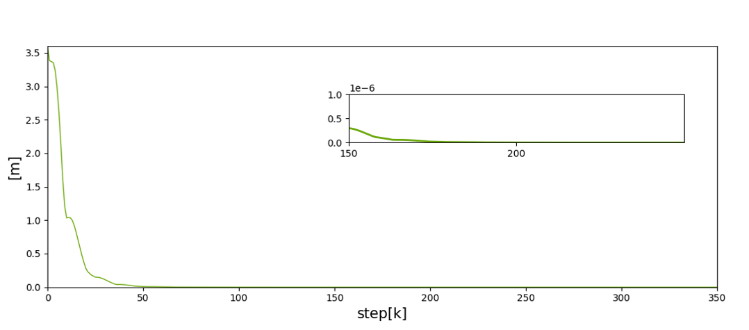
Figure 6: The formation tracking error 𝒑¯(k)delimited-∥∥bold-¯𝒑𝑘\left\lVert\boldsymbol{\bar{p}}(k)\right\rVert.

VI Simulation and Experiments

VI-A Numerical Simulations

This section contains simulation results to support the theoretical findings in this paper. We consider four UAVs tracking a moving target that only UAV 111 senses the target. For the discrete time Kuramoto model based algorithm (8), we give different initial value for θi(0)subscript𝜃𝑖0\theta_{i}(0), set the frequency ωi=π/2subscript𝜔𝑖𝜋2\omega_{i}=\pi/2 , and choose Kl=1subscript𝐾𝑙1K_{l}=1 for l{1,,n1}𝑙1𝑛1l\in\{1,...,n-1\}, and Kn=1subscript𝐾𝑛1K_{n}=-1. Let 𝒑^ij(0)=𝟎msubscriptbold-^𝒑𝑖𝑗0subscript0𝑚\boldsymbol{\hat{p}}_{ij}(0)=\mathbf{0}_{m} and Γij(0)=𝐈subscriptΓ𝑖𝑗0𝐈\varGamma_{ij}(0)=\mathbf{I} as the initial value for the least-square estimator (10), and choose βf=0.7subscript𝛽𝑓0.7\beta_{f}=0.7. We select T=0.125𝑇0.125T=0.125, β=7𝛽7\beta=7, U¯i=0.4subscript¯𝑈𝑖0.4\bar{U}_{i}=0.4 , and a¯ij=1/𝒩isubscript¯𝑎𝑖𝑗1normsubscript𝒩𝑖\bar{a}_{ij}=1/\|\mathcal{N}_{i}\| for the formation tracking controller (11).

The first simulation result, Fig. 2, shows the ability to cope with complex environments through affine transformation. The time-varying reference of the radius is ρ=2sin(kπ/100)+4𝜌2𝑘𝜋1004\rho=2\sin(k\pi/100)+4 by setting Sx=Sy=0.5sin(kπ/100)+1subscript𝑆𝑥subscript𝑆𝑦0.5𝑘𝜋1001S_{x}=S_{y}=0.5\sin(k\pi/100)+1 and the center corresponds to the moving target with 𝒑0(k)=[0.1k,3sin(π/150k)]Tsubscript𝒑0𝑘superscript0.1𝑘3𝜋150𝑘𝑇\boldsymbol{p}_{0}(k)=\left[0.1k,3\sin(\pi/150*k)\right]^{T}. At time step k=250𝑘250k=250, we assume that UAV 444 is damaged, and the remaining UAVs still can circle the target in a balanced pattern.

As shown in Fig. 3, we simulated tracking a moving target with 𝒑0(k)=[0.1k,0]Tsubscript𝒑0𝑘superscript0.1𝑘0𝑇\boldsymbol{p}_{0}(k)=\left[0.1k,0\right]^{T}. The centroid path of the formation gradually approaches the target path. Fig. 4 shows the relative phase between UAVs, thus pattern formation is achieved by the oscillator network (8). The relative position error and the formation tracking error can be seen in Fig. 5 and Fig. 6 respectively.

Refer to caption
Figure 7: Experimental results: (a) The path of the UAVs in XY𝑋𝑌XY-plane. (b) The position of UAVs in x𝑥x-axis and y𝑦y-axis respectively. The initial positions are represented in void style, and given the position of UAVs at time step k=250𝑘250k=250 in solid style.

.

Refer to caption
Figure 8: Experimental results: the relative position error max(i,j)¯𝒑~ij(k)subscript𝑖𝑗¯subscriptbold-~𝒑𝑖𝑗𝑘\max_{(i,j)\in\mathcal{\bar{E}}}\left\lVert\boldsymbol{\tilde{p}}_{ij}(k)\right\rVert.
Refer to caption
Figure 9: Formation tracking error 𝒑¯(k)delimited-∥∥bold-¯𝒑𝑘\left\lVert\boldsymbol{\bar{p}}(k)\right\rVert in the experiment.

VI-B Experimental Results

To further verify the real-time performance of the proposed method, an experiment of four Crazyflie 2.0 UAVs is implemented in an indoor testing area. One of the Crazyflies was considered as the target, flying at an altitude of z=0.3m𝑧0.3𝑚z=0.3m above the ground in a circle trajectory 𝒑0(k)=[cos(kπ/90),sin(kπ/90)]Tsubscript𝒑0𝑘superscript𝑘𝜋90𝑘𝜋90𝑇\boldsymbol{p}_{0}(k)=\left[\cos(k\pi/90),\sin(k\pi/90)\right]^{T}. The other three UAVs will be tracking the target at a higher altitude z=1.4m𝑧1.4𝑚z=1.4m. The UAVs are tracked by the OptiTrack motion capture system. We choose T=0.1𝑇0.1T=0.1, U¯i=0.3subscript¯𝑈𝑖0.3\bar{U}_{i}=0.3, and assume that all the UAVs can sense the target one. Thanks to the cascaded PID controller of Crazyflie 2.0, we control the UAVs by giving desired setpoints (1). The trajectory of the UAVs is mapped to XY𝑋𝑌XY-plane (see Fig. 7). Experimental results of the relative position error and the formation tracking error can be seen in Fig. 8 and Fig. 9 respectively. The errors may be due to the instability caused by wind disturbances between the UAVs and the existence of measurement errors. From the experimental results, we can conclude that the proposed control algorithm reaches a reasonable performance.

VII Conclusion

This paper presented a new control strategy to stabilize a group of UAVs to enclose a moving target via a distance-displacement-based relative localization method. By embedding the Kuramoto-based pattern design scheme into RLSE, we met the persistent excitation condition of relative displacements which is further facilitate the exponential convergence of relative position estimation. Then, a new framework based on affine transformations was proposed to obtain more complex time-varying formations to respond to more practical needs. Based on the relative position estimate, a formation tracking control scheme was designed to achieve the center of the formation tracking the moving target. The main advantage of this approach is that in the case of only a small number of UAVs sensing the target, the enclosing objective can also be realized. Numerical and empirical examples were used to demonstrate the theoretical findings. Future works will focus on extending this control strategy including some additional constraints such as adding potential terms to ensure obstacle avoidance and planning more flexible trajectories while ensuring that the persistent excitation condition is satisfied.

References

  • [1] K.-K. Oh, M.-C. Park, and H.-S. Ahn, “A survey of multi-agent formation control,” Automatica, vol. 53, pp. 424–440, 2015.
  • [2] Q. Zhang and H. H. Liu, “Aerodynamics modeling and analysis of close formation flight,” AIAA Journal of Aircraft, vol. 54, no. 6, pp. 2192–2204, Nov. 2017.
  • [3] H. Bayram, N. Stefas, K. S. Engin, and V. Isler, “Tracking wildlife with multiple uavs: System design, safety and field experiments,” in 2017 International Symposium on Multi-Robot and Multi-Agent Systems (MRS), 2017, pp. 97–103.
  • [4] V. Kratky, A. Alcantara, J. Capitan, P. Stepan, M. Saska, and A. Ollero, “Autonomous Aerial Filming With Distributed Lighting by a Team of Unmanned Aerial Vehicles,” IEEE Robotics and Automation Letters, vol. 6, no. 4, pp. 7580–7587, 2021.
  • [5] D. Tang, Q. Fang, L. Shen, and T. Hu, “Onboard Detection-Tracking-Localization,” IEEE/ASME Transactions on Mechatronics, pp. 1–1, 2020.
  • [6] G. Lopez-Nicolas, M. Aranda, and Y. Mezouar, “Adaptive Multirobot Formation Planning to Enclose and Track a Target With Motion and Visibility Constraints,” IEEE Transactions on Robotics, vol. 36, no. 1, pp. 142–156, 2020.
  • [7] L. Brinon-Arranz, A. Seuret, and C. Canudas-de-Wit, “Cooperative Control Design for Time-Varying Formations of Multi-Agent Systems,” IEEE Transactions on Automatic Control, vol. 59, no. 8, pp. 2283–2288, 2014.
  • [8] D. Klein and K. Morgansen, “Controlled collective motion for trajectory tracking,” in 2006 American Control Conference.   Minneapolis, MN, USA: IEEE, 2006, p. 7 pp.
  • [9] K. Hausman, J. Müller, A. Hariharan, N. Ayanian, and G. S. Sukhatme, “Cooperative multi-robot control for target tracking with onboard sensing,” The International Journal of Robotics Research, vol. 34, no. 13, pp. 1660–1677, 2015.
  • [10] P. Dames, P. Tokekar, and V. Kumar, “Detecting, localizing, and tracking an unknown number of moving targets using a team of mobile robots,” The International Journal of Robotics Research, vol. 36, no. 13-14, pp. 1540–1553, 2017.
  • [11] Y. Yu, Z. Li, X. Wang, and L. Shen, “Bearing-only circumnavigation control of the multi-agent system around a moving target,” IET Control Theory & Applications, vol. 13, no. 17, pp. 2747–2757, 2019.
  • [12] Y. Chang, Z. Sun, H. Zhou, X. Wang, L. Shen, and T. Hu, “Collaborative Target Tracking in Elliptic Coordinates: A Binocular Coordination Approach,” in 2021 American Control Conference (ACC).   New Orleans, LA, USA: IEEE, 2021, pp. 4741–4746.
  • [13] M. Deghat, I. Shames, B. D. O. Anderson, and C. Yu, “Localization and circumnavigation of a slowly moving target using bearing measurements,” IEEE Transactions on Automatic Control, vol. 59, no. 8, pp. 2182–2188, 2014.
  • [14] N. Ayanian, “DART: Diversity-enhanced Autonomy in Robot Teams,” The International Journal of Robotics Research, vol. 38, no. 12-13, pp. 1329–1337, 2019.
  • [15] X. Dong and G. Hu, “Time-Varying Formation Tracking for Linear Multiagent Systems With Multiple Leaders,” IEEE Transactions on Automatic Control, vol. 62, no. 7, pp. 3658–3664, 2017.
  • [16] F. Dörfler and F. Bullo, “Synchronization in complex networks of phase oscillators: A survey,” Automatica, vol. 50, no. 6, pp. 1539–1564, 2014.
  • [17] R. Sepulchre, D. A. Paley, and N. E. Leonard, “Stabilization of Planar Collective Motion: All-to-All Communication,” IEEE Transactions on Automatic Control, vol. 52, no. 5, pp. 811–824, 2007.
  • [18] ——, “Stabilization of Planar Collective Motion With Limited Communication,” IEEE Transactions on Automatic Control, vol. 53, no. 3, pp. 706–719, 2008.
  • [19] J. Wang, F. Gao, S. Shi, and J. Wang, “A New Method for Distance and Relative Velocity Measurement in Vehicle Collision Warning System,” in Sixth International Conference on Intelligent Systems Design and Applications, vol. 1.   Jian, China: IEEE, 2006, pp. 1142–1147.
  • [20] R. Zhang and S. Cao, “Extending Reliability of mmWave Radar Tracking and Detection via Fusion With Camera,” IEEE Access, vol. 7, pp. 137 065–137 079, 2019.
  • [21] J. Choi, S. Ulbrich, B. Lichte, and M. Maurer, “Multi-Target Tracking using a 3D-Lidar sensor for autonomous vehicles,” in 16th International IEEE Conference on Intelligent Transportation Systems (ITSC 2013).   The Hague, Netherlands: IEEE, 2013, pp. 881–886.
  • [22] A. Pearce, J. A. Zhang, R. Xu, and K. Wu, “Multi-Object Tracking with mmWave Radar: A Review,” Electronics, vol. 12, no. 2, p. 308, 2023.
  • [23] D. J. Klein, P. Lee, K. A. Morgansen, and T. Javidi, “Integration of Communication and Control Using Discrete Time Kuramoto Models for Multivehicle Coordination Over Broadcast Networks,” p. 7, 2007.
  • [24] T.-M. Nguyen, Z. Qiu, T. H. Nguyen, M. Cao, and L. Xie, “Persistently Excited Adaptive Relative Localization and Time-Varying Formation of Robot Swarms,” IEEE Transactions on Robotics, vol. 36, no. 2, pp. 553–560, 2020.
  • [25] Q. Zhang, “A tutorial on linear least square estimation,” 2022. [Online]. Available: https://arxiv.org/abs/2211.15347