Unidirectional spin wave emission by travelling pair of magnetic field profiles
Abstract
We demonstrate that the spin wave Cherenkov effect can be used to design the unidirectional spin wave emitter with tunable frequency and switchable direction of emission. In our numerical studies, we propose to use a pair of traveling profiles of the magnetic field which generate the spin waves, for sufficiently large velocity of their motion. In the considered system, the spin waves of shorter (longer) wavelengths are induced at the front (back) of the moving profiles and interfere constructively or destructively, depending on the velocity of the profiles. Moreover, we showed that the spin waves can be confined between the pair of traveling profiles of the magnetic field. This work opens the perspectives for the experimental studies in hybrid magnonic-superconducting systems where the magnetic vortices in a superconductor can be used as moving sources of the magnetic field driving the spin waves in the ferromagnetic subsystem.
keywords:
spin waves , Cherenkov effect , micomagnetic simulations , magnonics[inst1]organization=ISQI, Faculty of Physics, Adam Mickiewicz University,addressline=Uniwersytetu Poznańskiego 2, postcode=61-614, city=Poznań, country=Poland
1 Introduction
The Cherenkov and Doppler effects are the fundamental wave phenomena resulting from a uniform motion of the sources [1]. The Doppler effect is related to the change of the frequency of (monochromatic) wave source [2] due to its motion with constant velocity : [3], where or , depending if the transformation between reference frames is described by Galilean or Lorentz transformation. The Cherenkov effect [4] is observed as a generation of the waves by the source moving with the velocity equal to or larger than the phase velocity of the medium: . It is worth noting that this effect exists even if the ’source’ is ’static’ in moving reference frame: . In this case, the equation determines the frequency(ies) and the corresponding wave vector(s) of excited waves, which is(are) related by the condition: .
The Cherenkov effect was observed for the first time in 1934 when the -radiation emitted by pure liquids under the action of fast electrons ( - particles of radioactive elements) was detected [5]. The condition can be fulfilled because the velocity of the emitted electrons () exceeds the phase velocity of light in material medium of the refractive index . The first theoretical explanation of the Cherenkov effect was presented by I. Tamm and I. Frank [6] in the late thirties. Nowadays, the Cherenkov effect is the subject of intensive studies not only in the field of high-energy physics but also in condensed matter, and in particular in photonics [7,8] and derivated field: polaritonics [9,10,11,12]. It is worth mentioning that electromagnetic waves are not the only platform on which the Cherenkov effect can be studied and used in nanodevices. Magnonics [13] offers equally interesting possibilities. The phase velocities of spin waves are on the order of few km/s, making the Cherenkov effect relatively easy to observe.
Ten years ago, M. Yan [14,15] demonstrated numerically that Cherenkov effects for spin waves can be excited by the moving pulse of the magnetic field. The authors also found the formation of the Mach cones for 2D and 3D ferromagnetic systems. The experimental realization of this idea is challenging because it requires the generation of the fast-moving profile (barrier) of the magnetic field. Such motion can be approximated, in a time-lapse manner, by sequential application of the voltage to the long sequence of the electrodes deposited on the magnetic layer in which we can induce the magnetocrystalline anisotropy (and related effective field) [16]. Another approach, which is now intensively studied, is based on the motion of fluxons in the superconducting layer. The fluxons produce a stray field and can be pushed through a superconductor with large velocities [17,18]. It was already experimentally demonstrated that moving fluxons can induce a Cherenkov radiation of spin waves in the ferromagnetic layer underneath the superconductor [19].
The uniform motion of the medium leads also to Doppler or Cherenkov effect. This effect is well known in acoustics and has practical application in ultrasonography [20]. The corresponding effect is observed in magnonics if the spin wave is accompanied by the spin current flowing through the system [21] – i.e., the precessional dynamic of magnetization takes place on the top of the uniform motion of magnetic moments. In such systems, one can observe Doppler [22] of Cherenkov effect [23,24] for spin waves.
In our work, we do not consider the flow of spin current, but we focus on the spin wave generation by the motion of linear barriers of the magnetic field. Such a barrier, moving with a constant velocity, generates spin waves both in the forward and backward direction, with respect to the direction of the barrier’s motion. The forward and backward propagating spin waves differ in the wavelength [14], which makes the considered spin wave emitter non-reciprocal with a change in the direction of its motion. We propose to use pair of such barriers, which move in parallel, to construct the unidirectional spin wave emitter. Research on unidirectional spin wave emitters is being carried out by many groups [25,26]. The proposed system makes it possible to control the direction of spin wave propagation (forward or backward) by tuning the velocity of the profile. Moreover, we can block the emission of spin waves by confining them between moving barriers.
The article is organized as follows. After the introduction, we describe the system under consideration and present the principle of operation of the unidirectional emitter. Then, we briefly introduce the applied model and the computational technique. In the next section, we present the results for a single barrier [14], which is a reference system in our studies. After that, we discuss the outcomes for a pair of barriers illustrating three scenarios: forward emission, backward emission, and spin wave confinement. The work concludes with a summary.
2 Structure and model
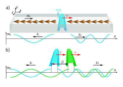
It is known [14,15] that fastly moving profile of a magnetic field can generate spin waves, which differ in the wavelength, depending on the direction of propagation (seeFig. 1(a)). This effect is known as a spin wave Cherenkov effect. Interestingly, the wavelength (wavenumber) of the forward and backward propagating spin waves changes with different rates as the velocity of the barrier increases (see Fig. 2(b)). This allows designing the unidirectional spin wave emitter where the spin waves produced by the pair of moving profiles of the magnetic field can interfere constructively or destructively on the opposite sides of the system – see Fig. 1(b). The conditions for the observation of the constructive (and destructive) interference in the front (and in the back) are not accidental and can be tuned by the adjustment of the selection of the velocity .
We considered a ferromagnetic stripe with a thickness of 10 nm and a width of 100 nm as a conduit for spin waves, which has been magnetized alongside the external field . It means the backward volume configuration for spin waves where their wave vector is parallel to the external field. We assumed that the ferromagnetic material (permalloy) is characterized by the saturation magnetization , exchange stiffness , and the low damping [15]. On both ends of the stripe, we implemented absorbing boundary conditions by gradually increasing the value of .
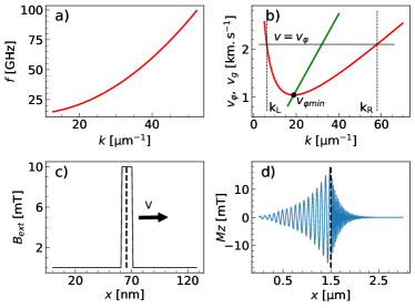
We used a modified version of Mumax3 [27], the GPU-accelerated micromagnetic software, which solves the Landau-Lifshitz-Gilbert equation to simulate the magnetization dynamics. To calculate the spin wave dispersion, we applied the harmonic (in time) and sinc-shaped (in space) pulse of magnetic field on one side of the magnetic stripe. We assumed the cut-off wave number 1/m and sweeped the frequency starting from 14 to 30 GHz by the steps of 0.5 GHz and from 30 to 100 GHz by steps of 1 GHz. After the time , we recorded the spin wave on the opposite side of the wire for each step of the simulations. The recorded spin wave profile was post-processed, using Fourier transform, to determine the leading wave vector corresponding to a given frequency. To observe the spin wave Cherenkov effect, we generated the moving profile of a magnetic field of rectangular shape ( 10 nm in width and = 10 mT in height) – see Fig. 2(c). We registered the spin waves excited by the moving profile of the magnetic field, for successive values of its velocity. The simulations were performed for different velocities of magnetic profile ranging from to . Such values are observed experimentally for moving sources of magnetic field in the form of superconducting vortices [28] in hybrid superconducting-magnonic systems [29].
3 Cherenkov radiation of spin waves
The Cherenkov effect for electromagnetic waves is usually associated with the radiation which occurs when a charged particle moves through a material with a higher velocity than the material’s phase velocity for light. When the charged particle moves with a velocity smaller than the phase velocity of light, there is a deformation of the electric polarisation in the material around the charged particle. In the reverse situation, when the velocity of the charged particle is larger than the phase velocity in the medium, the deformation of the electric field does not have the time to recover its initial state, so the deformation is extended on the particle trajectory, and creates an electromagnetic wave.
A similar effect is observed for spin waves when the magnetization is locally modified by the moving magnetic excitation (narrow profile of magnetic field). If the velocity of the excitation exceeds (the minimum value) of the phase velocity in the magnetic medium , the magnetization does not have the time to recover its initial state in the time of the flight of excitation and a spin wave is generated – see Fig. 1(a) and Fig. 2(b).
In our study, we are going to demonstrate that the pair of the profiles of the magnetic field moving parallelly at properly selected velocities can work as a unidirectional spin wave emitter – see Fig. 1(b). To test our numerical model and illustrate the principles of the spin wave Cherenkov effect, we reproduced the result of M. Yan [14, 15], where the motion of a single profile of magnetic field was considered.
Fig. 2(a) presents the numerically determined dispersion relation (frequency versus wave number) for the considered stripe (see Sec. 2). From the relation , we calculated the dependence of the spin wave phase (and group) velocity () on the wave number () – see Fig. 2(b). It is interesting to notice that the system has a threshold value of the phase velocity for spin waves, corresponding to the minimum of . According to the condition describing the spin wave Cherenkov emission, the spin waves cannot be generated when and for , the spin waves of two different wave numbers (and corresponding frequencies) are emitted. The minimum of corresponds to the contition: . Therefore, a wave with a smaller (larger) wave number will propagate with the slower (faster) that the field’s profile () and remain behind (overtake) the moving field’s profile.
4 Tunable, unidirectional spin wave emitter
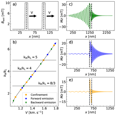
Let’s discuss now the working principles of unidirectional spin wave emitter presented in Fig. 1(b) where two square profiles of the magnetic field move with the same speed , keeping a constant gap between them (Fig. 1(b) and Fig. 3(a)).
To observe destructive (constructive) interference of two harmonic sources generating the waves of the wavevector and displaced by the distance , the wave number should fulfill the following condition: (), where is an integer number. In the considered system, we can tune the value of the wave vector of the generated spin wave by changing the velocity of the moving field’s profile. It is worth noting that this tuning takes place with a different rate for forward propagating spin waves (of larger wavenumber ) and backward propagating spin waves (of smaller wave ). It is known that the dipolar-exchange dispersion relation is linear: (quadratic ) for small (large) wave numbers. This corresponds to the relation: () for small (large) wave numbers. As a result, the ratio of will vary approximately linearly as the velocity increases – see Fig. 3(b). We can consider three particular scenarios.
-
1.
Backward spin wave emitter - constructive interference in the back and destructive interference in the front of moving barriers – Fig. 3(c):
(1) -
2.
Forward spin wave emitter - constructive interference in the back and destructive interference in the front of moving barriers – Fig. 3(d):
(2) -
3.
Spin wave confinement - constructive interference in the back and destructive interference in the front of moving barriers – Fig. 3(e):
(3)
The symbols and are two independent integer numbers.
For larger velocities (i.e. for km/s), the ratio is proportional to . As the velocity of the profiles increases, it can be tuned multiple times to every three mentioned scenarios. In is worth notting that the ratio must be grather that one: , which coresponds to the condition for Cherenkov emission .
Because of the damping, the constructive and destructive interferences cannot be perfect. However, the effects of unidirectional emissions are quite distinctive – see Fig. 3(a,b). The interfering waves decay exponentially with the rate for the exchange dominated regime, where the relaxation time is: and the group velocity: [30] ( is the static effective field, here: ). Then the amplitude of the interfering waves will change as , where is constant, the -(+) signs in the exponents refer to the right(left) popagating waves, and the -(+) sign between the terms in the brackets denotes the destuctively(constructively) interfering waves. This means that descuctively interfering waves are not canceled out immediately. This effect and the overall decay of interfering waves depends on the -number. However, the lack of perfect unidirectional emission and confinement cannot be attributed solely to the -dependent damping, but is possibly related to the occurrence of nonlinear effects in this externally pumped system.
5 Summary
Our simulations demonstrate that it is possible to use the spin wave Cherenkov emission to design the unidirectional (backward or forward) spin wave emitter of tunable frequency.
We showed that it is feasible to confine and continuously pump the bi-harmonic superposition of spin waves (i.e. the spin waves of two different frequencies).
The discussed effects can be potentially implemented in hybrid magic-superconducting systems where the Abricosov lattices vortices can be used as moving sources of the magnetic field that drives the spin waves in the ferromagnetic subsystem.
Data availibility
All of the simulations scripts, simulation outputs and post-processing code is open source and has been made available at https://doi.org/10.5281/zenodo.8328602
Acknowledgements
G. P. anf J. W. K. would like to acknowledge the erasmus mundus MaMaSELF programm and the support from the National Science Center – Poland grant No. 2021/43/I/ST3/00550.
References
[1] V. L. Ginzburg, Radiation by uniformly moving sources (Vav- ilov–Cherenkov effect, transition radiation, and other phenomena), Phys.- Usp. 39 (10) (1996) 973. doi:10.1070/PU1996v039n10ABEH000171.
[2] J. O. Perrine, The Doppler and Echo Doppler Effect, Am. J. Phys. 12 (1) (1944) 23–28. doi:10.1119/1.1990527.
[3] H. Berger, Complex Doppler effect in dispersive media, Am. J. Phys. 44 (9) (1976) 851–854. doi:10.1119/1.10136.
[4] G. S. Smith, Cherenkov radiation from a charge of finite size or a bunch of charges, Am. J. Phys. 61 (2) (1993) 147–155. doi:10.1119/1.17329.
[5] P. A. ˇCerenkov, Visible radiation produced by electrons moving in a medium with velocities exceeding that of light, Phys. Rev. 52 (1937) 378– 379. doi:10.1103/PhysRev.52.378.
[6] I. Frank, I. Tamm, Coherent visible radiation of fast electrons passing through matter, in: B. M. Bolotovskii, V. Y. Frenkel, R. Peierls (Eds.), I. E. Tamm: Selected Papers, Springer, Berlin – Heidelberg, 1991, Ch. 3, pp. 29–35. doi:10.1007/BF02783103.
[7] C. Luo, M. Ibanescu, S. G. Johnson, J. D. Joannopoulos, Cerenkov Radiation in Photonic Crystals, Science 299 (5605) (2003) 368–371. doi:10.1126/science.1079549.
[8] S. Xi, H. Chen, T. Jiang, L. Ran, J. Huangfu, B.-I. Wu, J. A. Kong, M. Chen, Experimental verification of reversed Cherenkov radiation in left-handed metamaterial, Phys. Rev. Lett. 103 (2009) 194801. doi: 10.1103/PhysRevLett.103.194801.
[9] S. Liu, P. Zhang, W. Liu, S. Gong, R. Zhong, Y. Zhang, M. Hu, Surface polariton Cherenkov light radiation source, Phys. Rev. Lett. 109 (2012) 153902. doi:10.1103/PhysRevLett.109.153902.
[10] P. Genevet, D. Wintz, A. Ambrosio, A. She, R. Blanchard, F. Capasso, Controlled steering of Cherenkov surface plasmon wakes with a one- dimensional metamaterial, Nat. Nanotechnol. 10 (9) (2015) 804–809. doi:10.1038/nnano.2015.137.
[11] N. Rivera, I. Kaminer, Light–matter interactions with photonic quasi- particles, Nat. Rev. Phys. 2 (10) (2020) 538–561. doi:10.1038/ s42254-020-0224-2.
[12] Y. Zhang, C. Hu, B. Lyu, H. Li, Z. Ying, L. Wang, A. Deng, X. Luo, Q. Gao, J. Chen, J. Du, P. Shen, K. Watanabe, T. Taniguchi, J.-H. Kang, F. Wang, Y. Zhang, Z. Shi, Tunable Cherenkov radiation of phonon polaritons in silver nanowire/hexagonal boron nitride heterostructures, Nano Lett. 20 (4) (2020) 2770–2777. doi:10.1021/acs.nanolett. 0c00419.
[13] A. V. Chumak, et al., Advances in magnetics roadmap on spin-wave com- puting, IEEE Trans. Magn 58 (6) (2022) 1–72. doi:10.1109/TMAG. 2022.3149664.
[14] M. Yan, C. Andreas, A. Kakay, F. Garcia-Sanchez, R. Hertel, Fast domain wall dynamics in magnetic nanotubes: Suppression of Walker breakdown and Cherenkov-like spin wave emission, Appl. Phys. Lett. 99 (12) (09 2011). doi:10.1063/1.3643037.
[15] M. Yan, A. Kakay, C. Andreas, R. Hertel, Spin-Cherenkov effect and magnonic mach cones, Phys. Rev. B 88 (2013) 220412. doi:10.1103/ PhysRevB.88.220412.
[16] B. Rana, Y. Otani, Towards magnonic devices based on voltage-controlled magnetic anisotropy, Commun. Phys. 2 (1) (2019) 1–12. doi:10.1038/ s42005-019-0189-6.
[17] O. V. Dobrovolskiy, D. Y. Vodolazov, F. Porrati, R. Sachser, V. M. Bevz, M. Y. Mikhailov, A. V. Chumak, M. Huth, Ultra-fast vortex motion in a direct-write Nb-C superconductor, Nature Commun. 11 (1) (2020) 3291. doi:10.1038/s41467-020-16987-y.
[18] O. V. Dobrovolskiy, R. Sachser, T. Bratcher, T. Bottcher, V. V. Kruglyak R. V. Vovk, V. A. Shklovskij, M. Huth, B. Hillebrands, A. V. Chu- mak, Magnon–fluxon interaction in a ferromagnet/superconductor het- erostructure, Nat. Phys. 15 (5) (2019) 477–482. doi:10.1038/ s41567-019-0428-5.
[19] O. V. Dobrovolskiy, Q. Wang, D. Y. Vodolazov, B. Budinska, S. Knauer, R. Sachser, M. Huth, A. I. Buzdin, Cherenkov radiation of spin waves by ultra-fast moving magnetic flux quanta (2023). arXiv:2103.10156. [20] D. H. Evans, W. N. McDicken, Doppler Ultrasound: Physics, Instrumen- tation and Signal Processing, 2nd Edition, Wiley, Berlin – Heidelberg, 1991.
[21] J. Fern´andez-Rossier, M. Braun, A. S. N´u˜nez, A. H. MacDonald, In- fluence of a uniform current on collective magnetization dynamics in a ferromagnetic metal, Phys. Rev. B 69 (2004) 174412. doi:10.1103/ PhysRevB.69.174412.
[22] V. Vlaminck, M. Bailleul, Current-induced spin-wave doppler shift, Sci- ence 322 (5900) (2008) 410–413. doi:10.1126/science.1162843. [23] J. Chen, H. Xia, X. Zeng, M. Yan, A micromagnetic study of the in- fluences of electric currents and magnetic fields on the spin-Cherenkov effect, Physica B: Condensed Matter 481 (2016) 59–62.
[24] A. de Kruijf, Spin waves and the spin Cherenkov effect, Ph.D. thesis, Eindhoven University of Technology (2017).
[25] V. N. Krivoruchko, A. S. Savchenko, V. V. Kruglyak, Electric-field con- trol of spin-wave power flow and caustics in thin magnetic films, Phys. Rev. B 98 (2018) 024427. doi:10.1103/PhysRevB.98.024427.
[26] R. A. Gallardo, P. Alvarado-Seguel, A. K´akay, J. Lindner, P. Landeros, Spin-wave focusing induced by dipole-dipole interaction in synthetic antiferromagnets, Phys. Rev. B 104 (2021) 174417. doi:10.1103/ PhysRevB.104.174417.
[27] A. Vansteenkiste, J. Leliaert, M. Dvornik, M. Helsen, F. Garcia-Sanchez, B. Van Waeyenberge, The design and verification of MuMax3, AIP Ad- vances 4 (10) (2014) 107133. doi:10.1063/1.4899186.
[28] V. Bevz, M. Mikhailov, B. Budinsk´a, S. Lamb-Camarena, S. Shpilinska, A. Chumak, M. Urb´anek, M. Arndt, W. Lang, O. Dobrovolskiy, Vortex counting and velocimetry for slitted superconducting thin strips, Phys. Rev. Appl. 19 (2023) 034098. doi:10.1103/PhysRevApplied.19. 034098.
[29] O. Dobrovolskiy, V. Bevz, E. Begun, R. Sachser, R. Vovk, M. Huth, Fast dynamics of guided magnetic flux quanta, Phys. Rev. Appl. 11 (2019) 054064. doi:10.1103/PhysRevApplied.11.054064.
[30] A. Prabhakar, D. D. Stancil, Spin Waves: Theory and Applications, Springer-Verlag, Springer New York, NY, 2009.