These authors contributed equally to this work.
[1]\fnmAlexey \surEremin\equalcontThese authors contributed equally to this work.
[1]\orgdivDepartment Nonlinear Phenomena, \orgnameInstitute of Physics, Otto von Guericke University, \orgaddress\streetUniversitaetsplatz 2, \cityMagdeburg, \postcode39106, \countryGermany 2]\orgdivDepartment Industrial Chemistry, \orgnameInstitute of Chemistry, Otto von Guericke University, \orgaddress\streetUniversitaetsplatz 2, \cityMagdeburg, \postcode39106, \countryGermany 3]\orgdivIndependent researcher \cityBensheim, \countryGermany 4]\orgdivMerck Electronics KGaA, \cityDarmstadt, \countryGermany
Fluid fibres in true 3D ferroelectric liquids
Abstract
We demonstrate an exceptional ability of a high-polarisation 3D ferroelectric liquid to form freely-suspended fluid fibres at room temperature. Unlike fluid threads in modulated smectics and columnar phases, where translational order is a prerequisite for forming liquid fibres, recently discovered ferroelectric nematic forms fibres with solely orientational molecular order. Additional stabilisation mechanisms based on the polar nature of the mesophase are required for this. We propose a model for such a mechanism and show that these fibres demonstrate an exceptional non-linear optical response and exhibit electric field-driven instabilities.
keywords:
liquid crystals, ferroelectrics, nonlinear optics1 Introduction
The phenomenon of freely suspended fluid fibres in non-Newtonian fluids is a fascinating topic with many practical applications. From living organisms to technological applications, such as spider silk, polymeric melts, textiles, and photonic devices, this phenomenon is observed in a wide range of areas [1, 2, 3]. Fibre-based materials are particularly desirable for wearable electronics due to their flexibility and stretchability, providing advantages over solid-state materials for the development of the next generation of electronic devices [4, 5]. Recent developments in smart materials and wearable design have created opportunities for the creation of structured and multifunctional materials, resulting in further research in this field.
Fibres can result from solidified liquids or glasses, which initially start as a liquid [6, 7]. In Newtonian liquids, long liquid filaments cannot form due to the Rayleigh-Plateau instability [8]. However, non-Newtonian fluids such as polymeric solutions and melts can form cylindrical filaments and jets during the process of thinning fluid bridges suspended between two supports or during droplet detachment [9].
The capillary-induced thinning of liquid filaments has been demonstrated in multiple studies as an effective method for characterising rheological materials [10, 11]. This approach can be utilised as a rheometric device for characterising rheological materials, which enables the determination of their flow and deformation properties under different conditions [11]. The usefulness of capillary-induced thinning of liquid filaments for rheological material characterisation and as a rheometric device has been demonstrated in several studies, making it a valuable tool in the field of materials science.
However, structured fluids, such as some types of liquid crystals, can form stable fibres [12, 13, 14]. Experiments with pure thermotropic liquid crystals have shown that the orientational anisotropy of nematics alone does not affect filament stability [12] . Columnar [15, 16, 17, 18, 19] or modulated smectic order [20, 21, 22, 23, 24] is the prerequisite for stabilising the filament structure.
Nematics are liquids exhibiting orientational molecular order and finding various applications from displays to electro-optics, photonics and sensorics [25]. Most nematics show quadrupolar uniaxial and rarely biaxial types of order. Possibility to stabilise the nematic phase assuming dipolar correlations were proposed by Max Born as early as 1916 [26]. The symmetry of such a liquid corresponds to that of the ferroelectric nematic. The dipolar symmetry of the NF phase sharply contrasts the quadrupolar symmetry of common nematics. It is accompanied by breaking the head-tail invariance of the nematic director. Although such symmetry breaking is quite common at interfaces, the experimental realisations of the bulk ferroelectricity in nematics remained elusive. A few polymeric and lyotropic systems showed indications of polar order in bulk. Only in 2017, Nishikawa et al. synthesised a thermotropic liquid crystal with a 1,3-dioxane unit in the mesogenic core (DIO) and exhibiting two nematic phases with a low-temperature phase distinguished by the spontaneous polarisation aligned with the director [27]. Around the same time, Mandle et al. designed a series of mesogens also exhibiting polymorphic nematic phases with a low-temperature ferroelectric nematic phase [28, 29].
Ferroelectric nematics are distinguished by an unusually high spontaneous polarisation typically within the range of a few µC cm-2 [30, 31, 32, 33, 34]. Mertelj and Sebastian have demonstrated that the transition into the NF phase involves a significant softening of splay deformations and an increase in polar correlations [35]. Consequently, electrostatic interactions play a very important role in defining the materials’ macroscopic properties. Avoiding the polarisation splay results in stiffening the splay elasticity [36]. Another necessary consequence of the polar symmetry in the nematic phase is the possibility of developing spontaneous splay, as theoretically investigated by Pleiner and Brand [37]. Although the field stabilised NF thread-like structures were found by Nishimura et al. [38] in experiments on electrostatic actuators, spontaneous formation of fibres remained unexplored.
In this paper, we experimentally demonstrate that ferroelectric nematics spontanously form liquid filaments. The filament formation occurs regardless of whether the compound undergoes a direct isotropic-NF or nematic-NF transition. These filaments can be created by mechanically pulling from a droplet or through the electro-capillary instability of a droplet in a vertical electric field. Using non-linear optical microscopy, we show that those filaments exhibit a remarkably efficient optical second harmonic generation. A model based on the polar structure of the phase is proposed to explain filament formation.
2 Results
2.1 Filament stability and optical properties
A striking feature of pulling filaments in the ferroelectric nematic becomes apparent when one is trying to pick a small amount of liquid crystal with a spatula from a vial. Long and occasionally, multiple fibres become attached to the spatula (Fig. 2a).
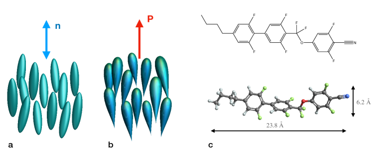
We explored this behaviour in two materials: compound 1 is a single-component mesogen exhibiting a direct transition from the isotropic to the ferroelectric nematic (NF) phase (Fig. 1):
isotropic (\qty19.6 NF) \qty44.0 crystal,
and material 2, a mixture exhibiting the transitions
isotropic \qty87.0 N \qty57.0 M \qty46.0 NF \qty-43.0 crystal.
Both compounds exhibit the room temperature NF with a high spontaneous polarisation in the rang of 5 - \qty6\micro\per\squared. The mesogen in compound 1 has a strong dipole moment , and its properties are described in [36, 39].
A drop of isotropic liquid spanned between two supports forms a catenoid-shaped profile of a liquid bridge formed by two menisci. Surface tension and the wetting conditions at the support determine its shape. As the distance between the supports increases, the bridge collapses due to the Plateau-Rayleigh instability.
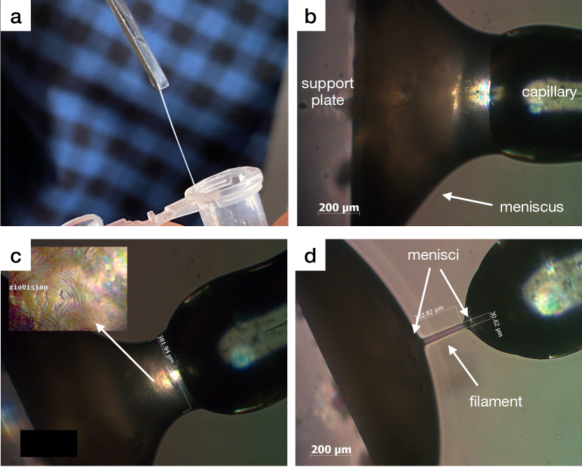
The bridge becomes birefringent when cooling to the nematic phase N (Fig. 2b). A grainy character of the microscopic texture observed between crossed polarisers suggests a disordered polydomain arrangement in the absence of the alignment within the meniscus. A slightly better alignment was observed in the central part of the bridge. Strong fluctuations of the nematic director result in the scattering of light observed as a typical flickering of the microscopic texture. Those fluctuations become quenched upon the transition into the intermediate M phase (Fig. 2c). The microscopic texture remains grainy in the meniscus and partially aligned in the central part of the bridge. Labyrinthine structures appear at the surface of the fluid bridge (Fig. 2c). The length of bridges in the N and M phases is not greater than that in the isotropic phase.
When entering the ferroelectric nematic phase NF, the situation changes drastically. The director fluctuations become visible again. Stretching the bridge above the critical length does not lead to immediate collapse. Rather, a cylindrical filament will form between the pair of separated menisci (Fig. 2d). Dust particles occasionally trapped at the filament surface help to visualise the material flow at the surface. The particles move slowly during the filament’s extension, now and then exhibiting slow circulating motion around the filament axis. These observations suggest that there is no significant flow present at the filament surface in the steady state.
Optical anisotropy indicates anisotropic molecular order, and most liquid crystals exhibit birefringence. In nematics, the birefringence is connected to the orientational order parameter. In the NF filaments, the slow optical axis (with the largest refractive index) points along the filament axis, as determined using a variable retarder. The experiments on aligned samples in planar cells showed that the same axis is parallel to the director in the N and the NF phases. This suggests that the molecular orientation in the filament is parallel to the filament axis. This phenomenon is akin to the case of spider silk formed by the hardening of silk fibres through the extensional flow.
2.2 Behaviour in electric field
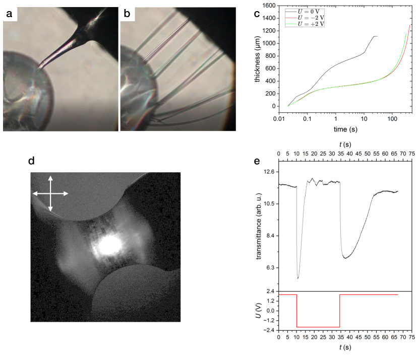
Spontaneous polarisation in the nematic phase gives rise to the whole zoo of remarkable effects in an electric field, such as explosive electrostatic instabilities in droplets [40], formation of dendritic structure in droplets [41], and behaviour of soliton walls in N [42], light-driven propulsion of ferroelectric droplets [43]. Fluid filaments also show remarkable behaviour in an external electric field applied axially along the filament axis. Thick bridges can switch between electrical and optical states when the field is reversed within a moderate range (as shown in Fig. 3 d,e). To demonstrate this, we can measure the optical transmittance of a bridge between crossed polarisers as the field is varied. When the voltage is reversed, the transmittance transiently decreases and increases again. However, if the same voltage is applied again after the field is removed, there is only a negligible change in transmittance.
In high fields, in the case of non-isolated electrodes, convective patterns occur, and the nematic alignment becomes disturbed.
Optical switching is not observed in thin filaments, but the electric field can have stabilising or destabilising effects depending on polarity. In the stabilising case, stronger fields can slow down or reverse thinning dynamics through the supply of material from the meniscus (Fig. 3c). However, field reversal can cause the collapse of the filament. Asymmetric metal/glass interfaces can lead to a destabilising field after the collapse of the filament, resulting in a bursting instability and a cluster of sideways-injected filaments (Fig. 3a,b).
However, if the filament is pulled from a droplet in an electric field, the field effect has a stabilising character independent of the polarity. As shown in Fig. 3c, applying the field as low as \qty2\per\micro increases the thinning time by order of magnitude compared to the field-free case.
2.3 Nonlinear optical behaviour
Ferroelectric nematics exhibit an exceptionally high second harmonic generation efficiency (SHG) [44, 45, 46]. This is a direct consequence of the polar mesophase symmetry and high values of the second-order molecular hyperpolarisability responsible for the conversion of the infrared light () of the primary beam to the second harmonic, SH (). As a result, the filaments prepared in the NF exhibit strong SH generation.
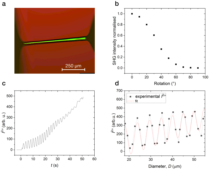
Fig. 4a exemplifies an image of a filament captured by SHG-microscopy. The record of the angular dependence of the SH signal shows that the highest signal is obtained when the polarisation of the primary laser beam is parallel to the filament axis (Fig. 4b), suggesting that the polar axis is aligned parallel to the nematic director in the NF phase. According to the Kleinman principle, symmetry of the NF phase results in the second-order polarisation:
| (1) |
where and are the second-order nonlinear optical coefficients in a coordinate frame with axis ”3” (Z) directed along the polar axis of the nematic. Thus, the fundamental light polarised along the axis (extraordinary) of a thin NF slab results in the SHG determined by . The light polarised orthogonal to the axis generates an SH signal determined by .
As the thickness of the slab is varied, the exhibits a typical periodic dependence called Maker fringes. This occurs due to the energy exchange between the primary and the SH beams (see also Fig. 5b).
In the case of a plane parallel slab, the Maker fringes can be described by the equation:
| (2) |
where the coefficient is determined by the Fresnel transmission coefficients for the fundamental, the SH lights, is the wavelength, and is the sample thickness, is the effective NLO coefficient, and is the dispersion. Thus, analysis of Maker fringes allows us to estimate the LC material’s second-order nonlinear optical (NLO) coefficients of the LC material [47, 48, 49].
To determine the NLO coefficients, we can use the periodicity of the fringe pattern to calculate the difference in refractive indices, even if we don’t know the exact values of and . By comparing the maximal intensities to those of a reference like -Quartz, we can extract the NLO coefficients for the material under study.
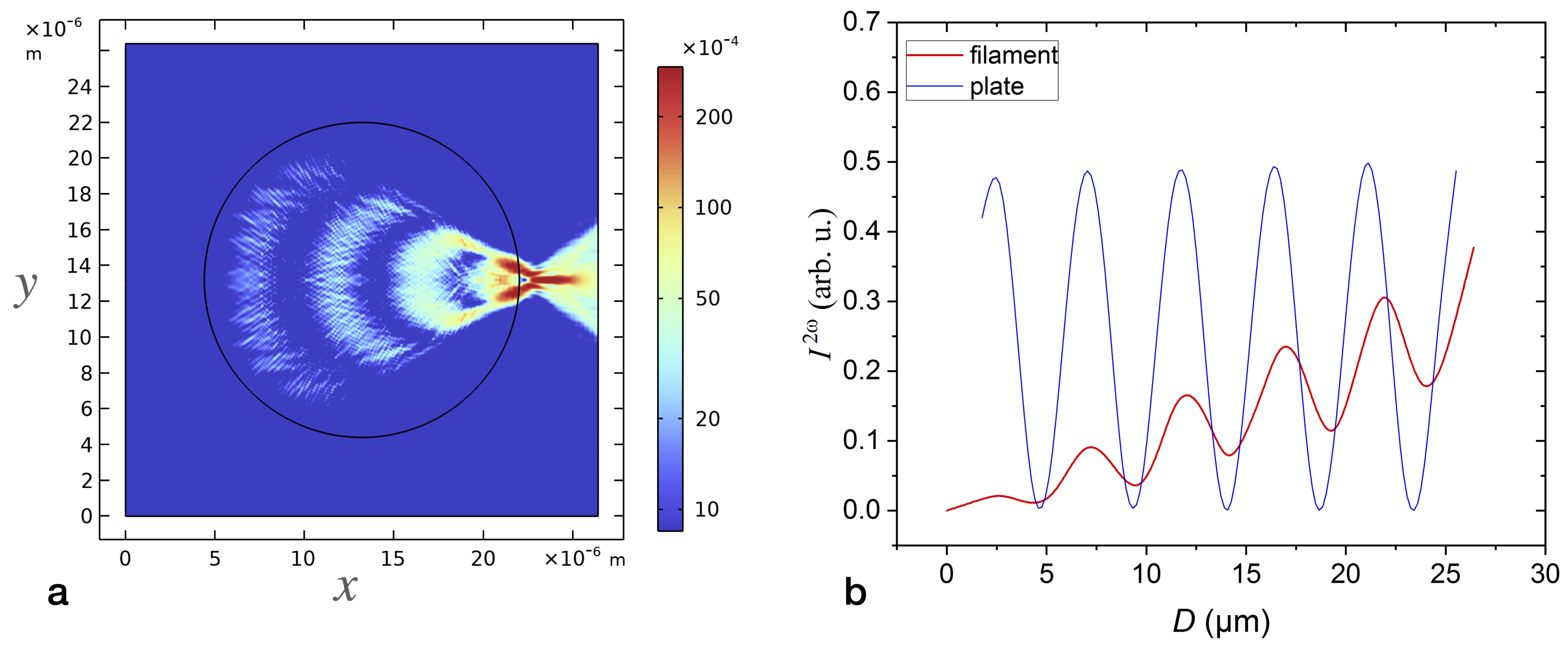
In the case of filaments, the thickness dependence of can be recorded during filament thinning. However, the fringe pattern is different from that of the plane parallel slab. The periodic fringe pattern is superimposed with a baseline growing with increasing filament diameter. In the range of rather small diameters , the fringe pattern can be approximated by the function
| (3) |
where and are fit parameters for the baseline and the amplitude, respectively.
The difference occurs due to the circular shape of the filament cross-section allowing the rays with different path lengths to contribute to the net SH power. A simulation of the SH generation in a filament using the finite element method is shown in Fig. 5 qualitatively confirms this behaviour. The net power exhibits fringes within the filament cross-section as shown in Fig. 5a.
Even in this case, the period of the fringe pattern equals . This allows us to determine from the thickness dependence of the . The slope of the baseline allows us to roughly estimate the nonlinear optical coefficient of the filament material. The simulation in Fig. 5b compares the thickness dependences of the SHG signal of a filament and a reference slab with identical coefficients . Taking the mean intensity of the slab as a reference, the baseline of the normalised filament intensity is proportional to the diameter , , where . The same approach can be applied to the experimental data giving the ratio
| (4) |
where is the nonlinear optical coefficient of -Quartz. The slope of the baseline determined in the experiment is giving an estimation .
This value is more than five times higher than that of -Quartz, making this material stand out. At the same time, it is smaller than the values reported by Folcia et al. [44] for another ferroelectric nematogen mesogen, RM734, aligned in an electric field. This difference can be attributed to the different chemical structures of our compounds containing several fluorine substituents.
3 Discussion
Polar, SHG-active filaments were initially discovered in the polarisation-modulated smectic phase of bent-core liquid crystals [21, 23]. These filaments display exceptional stability for a few days. In contrast, the stability range of the nematic filaments is restricted to 10 - 30 seconds in compound 1 to several minutes in material 2. The filaments thin retaining their cylindrical shape until they eventually break. What is the reason for the stability of the nematic filaments?
In polymeric systems, it is the nonlinear rheology responsible for filament formation. Intensive theoretical and experimental studies of the filament formation and jet break-up showed that extensional rheological response dictates whether or not a stable filament is formed [9, 50, 51]. During the necking process, as a fluid bridge is thinning, elastic tensile stresses resist the pinching driven by the capillary forces [11]. In our case, however, the mesogens are low-weight molecules. In the whole temperature range of the liquid crystal phases, the rheological behaviour is Newtonian with a linear flow curve (Fig. 6a), excluding this mechanism of filament stabilisation.
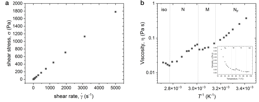
The viscosity exhibits Arrhenius dependence in the conventional and ferroelectric nematic phases (N and NF). Non-Arrhenius behaviour occurs in the intermediate M phase. It appears that nematic filaments occur only in the ferroelectric nematic phase regardless the presence of the mesophase above NF. Same behaviour is observed in compounds with the direct iso-NF and iso–N–M–NF transitions. These observations suggest that ferroelectric polarisation is essential for filament stability. Indeed the instability of a fluid cylinder occurs due to the growth of surface distortion modes when the aspect ratio of the cylinder exceeds a critical value. Those distortions are accompanied by the decrease of the surface energy, driving the system to a state where the liquid is confined to a set of spherical droplets. A sinusoidal distortion of the fluid cylinder of an initial radius is given by the radius dependence , where is the distortion amplitude, is the wave number, and is the modified cylinder radius under the assumption of the volume conservation. The corresponding contribution of the surface energy is expressed by the formula:
| (5) |
While the surface energy is quadratically dependent on , the undistorted state’s stability hinges on the prefactor . Exceeding an aspect ratio of triggers instability in the lowest mode with , which is referred to as the Rayleigh-Plateau limit.
Distortions in the form of surface undulations result in the deformation of the nematic director within the filament. Such deformations are driven by the strong anchoring at the liquid/air interface. The distortion of the director field in bulk is controlled by the nematic elasticity and determined by the splay, twist and bend elastic constants (, , , respectively) [25]. Assuming planar anchoring at the filament’s interface and parametrising the nematic director using the angle as , we obtain in one-constant approximation () from a solution of the Laplace equation (Eq. 7).
In the ferroelectric nematic with , surface undulations are accompanied by the splay of the director and, as a result, by undulations of the spontaneous polarisation. Since the polarisation splay results in the bound electric charge density , the surface undulations will cost electrostatic energy. As Bellini et al. [52] demonstrated the ferroelectric nematic phase confined in microchannels exhibits a unique property known as electric ”super-screening.” This phenomenon enables the polarisation in the N to be restricted to a designated channel or filament, guiding the electric field. Specifically, any transverse electric field that exists with respect to the filament axis is rapidly compensated for by the induced bound electric charges. This compensation process leads to a confinement of the electric field of the polarised filament within the filament itself. Electric displacement in a ferroelectric is given by the equation , where is the electric field and is the remanent displacement, equivalent to the spontaneous polarization . Assuming no free charges, introducing the electric potential with we can derive from the Poisson equation , where the term represents the density of the bound charges and is determined by the deformation of the polar director field as . The solutions of Eqs. 6 and 7 provides required potential:
| (6) |
| (7) |
The electrostatic energy is determined by the integration over the volume of the filament:
| (8) |
Numerical solutions of the Eqs. 6 and 7 for an exemplary filament of the length and the initial radius are shown in Fig. 7a. The filament’s surface is undulated with , . The potential has an axial symmetry and exhibits a modulation as shown in the cross-section in Fig. 7b together with the residual displacement .
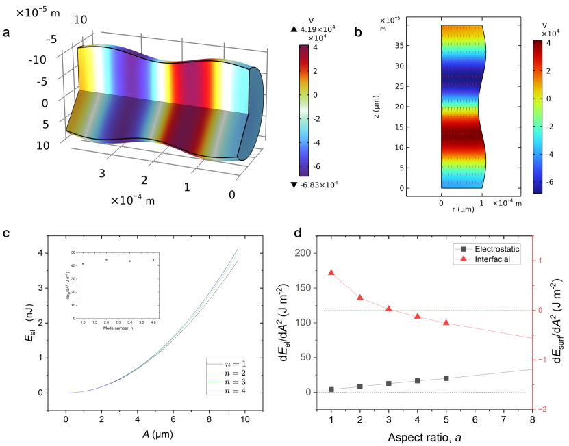
By keeping the modulation amplitude below 10% of , the electrostatic energy increases quadratically with and is mostly unaffected by the mode number (Fig. 7c). The slope only slightly increases with higher wave numbers. As a result, thus it is adequate to only consider the lowest mode with . With the elastic constant in the range of piconewtons, the elastic energy given by the energy density term is several orders of magnitude smaller than the surface [53] and electrostatic contributions.
When the length of a filament increases while the radius is fixed, the slope linearly increases with the aspect ratio (black curve in Fig. 7d). Conversely, the surface energy decreases as the aspect ratio increases, and the slope changes sign from positive to negative, ultimately making long filaments unstable (red curve in Fig. 7d).
However, the electrostatic contribution exceeds the surface one by almost an order of magnitude, which explains why the breaking instability is suppressed. A drastic slowing down of the thinning dynamics in filaments prepared in an electric field is another confirmation that the stabilisation is of electrostatic origin. Indeed the field-guiding property of the NF filament [52] results in an electric field induced by the polarisation charges at the junctions to the menisci. The filament acts as a capacitor, and the electric field couples to the spontaneous polarisation within the fibre. Nonetheless, this stabilisation mechanism does not prevent the filament’s thinning from occurring due to the transversal tension and material transport into the menisci. Another structural feature contributing to filament stabilisation is required to sustain the transversal stresses. One possible mechanism is the conjectured spontaneous polarisation splay creating a smectic or columnar-type superstructure that can balance the transversal stresses. Such splay is of flexoelectric nature and is the consequence of the symmetry of N. The linear splay term is proposed in the theoretical models of the N phase [37, 54, 29, 55]. The experimental observations of the spontaneous splay were suggested by Mertelj and Sebastián in [55] using photo-patterned substrates. A detailed theoretical description accounting for the conductivity, free charges, and polarisation fluctuations is required to accurately describe the stability of the N filaments.
4 Conclusion
In summary, we demonstrated that the recently discovered ferroelectric nematic phase can form freely suspended filaments in a addition to freely suspended films. The filaments exhibit a remarkable efficiency of the optical second harmonic conversion and their stability is strongly dependent on the external electric field.
Although those features are rather typical for the (modulated) smectic and columnar phases, they are yet observed in the nematic phase suggesting the suppression of the surface fluctuations and probably the presence of the polarisation-driven secondary structure such as a periodic director modulation.
5 Methods
Materials. We investigated two liquid crystal compounds both synthesised and provided by Merck Electronic KGaA: Compound 1 is 4-((4’-butyl-2’,3,5,6’-tetrafluoro[1,1’-biphenyl]-4-yl)difluoromethoxy)-2,6-difluorobenzonitrile exhibiting a monotropic ferroelectric nematic phase near room temperature. The phase diagram is isotropic (\qty19.6 NF) \qty44.0 crystal.
Material 2 is a mixture exhibiting the nematic (N), an intermediate unclassified M phase, and the ferroelectric nematic (NF) phases: isotropic \qty87.0 N \qty57.0 M \qty46.0 \qty-43.0 crystal.
Polarised light microscopy. Optical studies were made using a polarised light microscope AxioImager A.1 (Carl Zeiss GmbH, Germany) equipped with a heating stage (Instec, USA). Using a custom-made pulling device, the filaments were pulled mechanically in a heating stage. Birefringence measurements were done using the Berek tilting compensator.
Nonlinear optical microscopy. The generation of the optical second harmonic (SHG) was measured using the multiphoton laser of a confocal microscope (Leica TCS SP8, CLSM). A tunable IR laser () was used as a fundamental light beam, and the emission was acquired at . As a reference, we used a \qty50\micro -quartz crystal plate (z-cut).
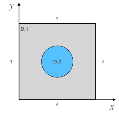
Data analysis and simulations. Data analysis and numerical simulations were made using Matlab (Mathworks) and Comsol software. To simulate SHG in filaments, we solved coupled equations for the fundamental and SH electromagnetic waves in the frequency domain. The geometrical domain is composed of an outer rectangular domain D.1 and the inner cylinder with a circular cross-section in the -plane (domain D.2) as shown in Fig. 8. The cylinder’s radius was varied from to to simulate the radius dependence of the SHG signal.
We considered a plane wave polarised along the cylinder axis propagating in -direction: . The fundamental and the SH waves satisfy the wave equation:
| (9) |
where for the fundamental and the SH waves, respectively. The polarisation contains a sum of linear and non-linear contributions:
| (10) |
In the case of -polarised beam, the nonlinear polarisation in the domain D.2 is determined by the coefficient:
| (11) |
At the domain D.1 boundaries 1 and 2 satisfy scattering boundary conditions for the fundamental wave:
| (12) |
with for boundary 1, and for boundary 2, and is the normal to the boundary. The same conditions are satisfied for the SH wave with at both boundaries. The conditions for the inner boundary between the domains D.1 and D.2 are continuous.
Acknowledgments
The authors would like to thank Antal Jákli, Joseph Maclennan, Michail Osipov and Tommaso Bellini for fruitful discussions. N and their electromechanical properties were also demonstrated by A. Jákli at European Liquid Crystal Conference in Rende (Italy) [56].
The authors acknowledge the financial support of Deutsche Forschungsgemeinschaft (Project ER 467/8-3).
Declarations
There are no conflicts to declare.
References
- \bibcommenthead
- Vollrath and Knight [2001] Vollrath, F., Knight, D.: Liquid crystalline spinning of spider silk. Nature 410(6828), 541–548 (2001) https://doi.org/10.1038/35069000
- Kerkam et al. [1991] Kerkam, K., Viney, C., Kaplan, D., Lombardi, S.: Liquid crystallinity of natural silk secretions. Nature 349, 596–598 (1991) https://doi.org/10.1038/349596a0
- Wang et al. [2023] Wang, M.-Y., Zhang, J.-P., Chen, S.-L., Qi, B., Yao, X.-Y., Zhang, X.-H., Li, Y.-T., Yang, Z.-H.: Dry-Spinning of Artificial Spider Silk Ribbons from Regenerated Natural Spidroin in an Organic Medium. Macromolecular Rapid Communications, 2300024 (2023) https://doi.org/10.1002/marc.202300024
- Stoppa and Chiolerio [2014] Stoppa, M., Chiolerio, A.: Wearable Electronics and Smart Textiles: A Critical Review. Sensors 14(7), 11957–11992 (2014) https://doi.org/10.3390/s140711957
- Heo et al. [2018] Heo, J.S., Eom, J., Kim, Y., Park, S.K.: Recent Progress of Textile-Based Wearable Electronics: A Comprehensive Review of Materials, Devices, and Applications. Small 14(3), 1703034 (2018) https://doi.org/10.1002/smll.201703034
- Mercader et al. [2010] Mercader, C., Lucas, A., Derré, A., Zakri, C., Moisan, S., Maugey, M., Poulin, P.: Kinetics of fiber solidification. Proceedings of the National Academy of Sciences 107(43), 18331–18335 (2010) https://doi.org/10.1073/pnas.1003302107
- Sparkes and Holland [2019] Sparkes, J., Holland, C.: The Energy Requirements for Flow-Induced Solidification of Silk. Macromolecular Bioscience 19(3), 1800229 (2019) https://doi.org/10.1002/mabi.201800229
- Rayleigh [1879] Rayleigh, L.: On the capillary phenomena of jets. Proceedings of the Royal Society of London A: Mathematical, Physical and Engineering Sciences 28, 190–195 (1879)
- Goldin et al. [1969] Goldin, M., Yerushalmi, J., Pfeffer, R., Shinnar, R.: Breakup of a laminar capillary jet of a viscoelastic fluid. Journal of Fluid Mechanics 38(4), 689–711 (1969) https://doi.org/10.1017/s0022112069002540
- Clasen et al. [2006] Clasen, C., Eggers, J., Fontelos, M.A., Li, J., Mckinley, G.H.: The beads-on-string structure of viscoelastic threads. Journal of Fluid Mechanics 556, 283–308 (2006) https://doi.org/10.1017/s0022112006009633
- Anna and McKinley [2001] Anna, S.L., McKinley, G.H.: Elasto-capillary thinning and breakup of model elastic liquids. Journal of Rheology 45(1), 115–138 (2001) https://doi.org/10.1122/1.1332389
- Mahajan et al. [1999] Mahajan, M., Tsige, M., Taylor, P., Rosenblatt, C.: Liquid crystal bridges. Liquid Crystals 26(3), 443–448 (1999) https://doi.org/10.1080/026782999205227
- Cheong et al. [2001] Cheong, A.G., Rey, A.D., Mather, P.T.: Capillary instabilities in thin nematic liquid crystalline fibers. Physical Review E 64, 041701 (2001) https://doi.org/10.1103/PhysRevE.64.041701
- Cheong and Rey [2002] Cheong, A.-G., Rey, A.D.: Temperature effects on capillary instabilities in a thin nematic liquid crystalline fiber embedded in a viscous matrix. The European Physical Journal E - Soft Matter 9(2), 171–193 (2002) https://doi.org/10.1140/epje/i2002-10083-3
- Gharbia et al. [1990] Gharbia, M., Gharbi, A., Cagnon, M., Durand, G.: Capillary oscillations and instabilities of discotic liquid crystal threads. Journal de Physique 51(12), 1355–1365 (1990) https://doi.org/10.1051/jphys:0199000510120135500
- Fontes et al. [1988] Fontes, E., Heiney, P., Jeu, W.: Liquid-crystalline and helical order in a discotic mesophase. Physical Review Letters 61(10), 1202–1205 (1988) https://doi.org/10.1103/PhysRevLett.61.1202
- Safinya et al. [1985] Safinya, C.R., Clark, N.A., Liang, K.S., Varady, W.A., Chiang, L.Y.: Synchrotron X-ray Scattering Study of Freely Suspended Discotic Strands. Molecular Crystals and Liquid Crystals 123(1), 205–216 (1985) https://doi.org/10.1080/00268948508074778
- Kamenskii and Kats [1983] Kamenskii, V.G., Kats, E.I.: Stability of filaments of discotic liquid crystals. Soviet Journal of Experimental and Theoretical Physics Letters 37, 261 (1983)
- van Winkle and Clark [1982] Winkle, D.H., Clark, N.A.: Freely Suspended Strands of Tilted Columnar Liquid-Crystal Phases: One-Dimensional Nematics with Orientational Jumps. Physical Review Letters 48(20), 1407–1410 (1982) https://doi.org/10.1103/physrevlett.48.1407
- Bailey et al. [2007] Bailey, C., Gartland, E.C., Jákli, A.: Structure and stability of bent core liquid crystal fibers. Physical Review E 75(3), 031701 (2007) https://doi.org/10.1103/PhysRevE.75.031701
- Jákli et al. [2003] Jákli, A., Krüerke, D., Nair, G.G.: Liquid crystal fibers of bent-core molecules. Physical Review E 67, 051702 (2003) https://doi.org/10.1103/PhysRevE.67.051702
- Eremin et al. [2005] Eremin, A., Nemes, A., Stannarius, R., Schulz, M., Nadasi, H., Weissflog, W.: Structure and mechanical properties of liquid crystalline filaments. Physical Review E 71(3), 031705 (2005) https://doi.org/10.1103/PhysRevE.71.031705
- Eremin et al. [2012] Eremin, A., Kornek, U., Stern, S., Stannarius, R., Araoka, F., Takezoe, H., Nádasi, H., Weissflog, W., Jákli, A.: Pattern-Stabilized Decorated Polar Liquid-Crystal Fibers. Physical Review Letters 109(1), 017801 (2012) https://doi.org/10.1103/physrevlett.109.017801
- Tamba et al. [2015] Tamba, M.-G., Salili, S.M., Zhang, C., Jákli, A., Mehl, G.H., Stannarius, R., Eremin, A.: A fibre forming smectic twist-bent liquid crystalline phase. RSC Advances 5, 11207 (2015) https://doi.org/10.1039/c4ra14669g
- de Gennes and Prost [1995] Gennes, P.G., Prost, J.: The Physics of Liquid Crystals. Clarendon Press. Clarendon Press, London (1995)
- Born [1916] Born, M.: Über anisotrope Flüssigkeiten. Versuch einer Theorie der flüssigen Kristalle und des elektrischen Kerr-Effekts in Flüssigkeiten. Sitzungsber. Preuss. Akad Wiss. 30, 614–650 (1916)
- Nishikawa et al. [2017] Nishikawa, H., Shiroshita, K., Higuchi, H., Okumura, Y., Haseba, Y., Yamamoto, S.-i., Sago, K., Kikuchi, H.: A fluid liquid-crystal material with highly polar order. Advanced Materials 29(43), 1702354 (2017) https://doi.org/10.1002/adma.201702354
- Mandle et al. [2017] Mandle, R.J., Cowling, S.J., Goodby, J.W.: A nematic to nematic transformation exhibited by a rod-like liquid crystal. Phys. Chem. Chem. Phys. 19, 11429–11435 (2017) https://doi.org/10.1039/C7CP00456G
- Mertelj et al. [2018] Mertelj, A., Cmok, L., Sebastián, N., Mandle, R.J., Parker, R.R., Whitwood, A.C., Goodby, J.W., Čopič, M.: Splay Nematic Phase. Physical Review X 8(4), 041025 (2018) https://doi.org/%****␣main.tex␣Line␣1025␣****10.1103/physrevx.8.041025
- Lavrentovich [2020] Lavrentovich, O.: Ferroelectric nematic liquid crystal, a century in waiting - commentary. Proceedings of the National Academy of Sciences 117(26), 14629–14631 (2020)
- Chen et al. [2020] Chen, X., Korblova, E., Dong, D., Wei, X., Shao, R., Radzihovsky, L., Glaser, M.A., Maclennan, J.E., Bedrov, D., Walba, D.M., Clark, N.A.: First-principles experimental demonstration of ferroelectricity in a thermotropic nematic liquid crystal: Polar domains and striking electro-optics. Proceedings of the National Academy of Sciences of the United States of America 117(25), 14021–14031 (2020) https://doi.org/10.1073/pnas.2002290117
- Mandle et al. [2021] Mandle, R.J., Sebastián, N., Martinez-Perdiguero, J., Mertelj, A.: On the molecular origins of the ferroelectric splay nematic phase. Nature Communications 12(1), 4962 (2021) https://doi.org/10.1038/s41467-021-25231-0 2011.02722
- Brown et al. [2021] Brown, S., Cruickshank, E., Storey, J.M.D., Imrie, C.T., Pociecha, D., Majewska, M., Makal, A., Gorecka, E.: Multiple Polar and Non-polar Nematic Phases. ChemPhysChem 22(24), 2506–2510 (2021) https://doi.org/10.1002/cphc.202100644
- Sebastián et al. [2021] Sebastián, N., Mandle, R.J., Petelin, A., Eremin, A., Mertelj, A.: Electrooptics of mm-scale polar domains in the ferroelectric nematic phase. Liquid Crystals 48(14), 2055–2071 (2021) https://doi.org/10.1080/02678292.2021.1955417 2103.10215
- Sebastián et al. [2020] Sebastián, N., Cmok, L., Mandle, R.J., Fuente, M.R.d.l., Olenik, I.D., Copic, M., Mertelj, A.: Ferroelectric-Ferroelastic Phase Transition in a Nematic Liquid Crystal. Physical Review Letters 124(3), 037801 (2020) https://doi.org/10.1103/physrevlett.124.037801
- Zavvou et al. [2022] Zavvou, E., Klasen-Memmer, M., Manabe, A., Bremer, M., Eremin, A.: Polarisation-driven magneto-optical and nonlinear-optical behaviour of a room-temperature ferroelectric nematic phase. Soft Matter 18(46), 8804–8812 (2022) https://doi.org/10.1039/d2sm01298g 2206.08017
- Pleiner and Brand [1989] Pleiner, H., Brand, H.R.: Spontaneous Splay Phases in Polar Nematic Liquid Crystals. Europhysics Letters 9(3), 243–249 (1989) https://doi.org/10.1209/0295-5075/9/3/010
- Nishimura et al. [2022] Nishimura, S., Masuyama, S., Shimizu, G., Chen, C.-Y., Ichibayashi, T., Watanabe, J.: Lowering of Electrostatic Actuator Driving Voltage and Increasing Generated Force Using Spontaneous Polarization of Ferroelectric Nematic Liquid Crystals. Advanced Physics Research 1(1), 2200017 (2022) https://doi.org/10.1002/apxr.202200017
- Manabe et al. [2021] Manabe, A., Bremer, M., Kraska, M.: Ferroelectric nematic phase at and below room temperature. Liquid Crystals 48(8), 1–8 (2021) https://doi.org/10.1080/02678292.2021.1921867
- Barboza et al. [2022] Barboza, R., Marni, S., Ciciulla, F., Mir, F.A., Nava, G., Caimi, F., Zaltron, A., Clark, N.A., Bellini, T., Lucchetti, L.: Explosive electrostatic instability of ferroelectric liquid droplets on ferroelectric solid surfaces. Proceedings of the National Academy of Sciences 119(32), 2207858119 (2022) https://doi.org/10.1073/pnas.2207858119 2205.06353
- Máthé et al. [2023] Máthé, M.T., Farkas, B., Péter, L., Buka, A., Jákli, A., Salamon, P.: Electric field-induced interfacial instability in a ferroelectric nematic liquid crystal. Scientific Reports 13(1), 6981 (2023) https://doi.org/10.1038/s41598-023-34067-1
- Basnet et al. [2022] Basnet, B., Rajabi, M., Wang, H., Kumari, P., Thapa, K., Paul, S., Lavrentovich, M.O., Lavrentovich, O.D.: Soliton walls paired by polar surface interactions in a ferroelectric nematic liquid crystal. Nature Communications 13(1), 3932 (2022) https://doi.org/10.1038/s41467-022-31593-w
- Marni et al. [2023] Marni, S., Nava, G., Barboza, R., Bellini, T.G., Lucchetti, L.: Walking Ferroelectric Liquid Droplets with Light. Advanced Materials 35(22), 2212067 (2023) https://doi.org/10.1002/adma.202212067
- Folcia et al. [2022] Folcia, C.L., Ortega, J., Vidal, R., Sierra, T., Etxebarria, J.: The ferroelectric nematic phase: an optimum liquid crystal candidate for nonlinear optics. Liquid Crystals 49, 866 (2022)
- Nishikawa and Araoka [2021] Nishikawa, H., Araoka, F.: A New Class of Chiral Nematic Phase with Helical Polar Order. Advanced Materials 33(35), 2101305 (2021) https://doi.org/10.1002/adma.202101305
- Li et al. [2021] Li, J., Nishikawa, H., Kougo, J., Zhou, J., Dai, S., Tang, W., Zhao, X., Hisai, Y., Huang, M., Aya, S.: Development of ferroelectric nematic fluids with giant- dielectricity and nonlinear optical properties. Science Advances 7(17), 5047 (2021) https://doi.org/10.1126/sciadv.abf5047 2011.14099
- Vivek et al. [2021] Vivek, P., Suvitha, A., Jauhar, R.M., Steephen, A., Arunkumar, R., Karunagaran, N., Kowsalya, M., Rekha, M.: Determination of SHG by Maker fringes studies on unidirectional grown guanidinium chlorochromate single crystal for NLO device applications. Journal of Optics 50(1), 77–82 (2021) https://doi.org/10.1007/s12596-020-00664-w
- Okamoto et al. [1992] Okamoto, N., Hirano, Y., Sugihara, O.: Precise estimation of nonlinear-optical coefficients for anisotropic nonlinear films with symmetry. Journal of the Optical Society of America B 9(11), 2083 (1992) https://doi.org/10.1364/josab.9.002083
- Jerphagnon and Kurtz [1970] Jerphagnon, J., Kurtz, S.K.: Maker Fringes: A Detailed Comparison of Theory and Experiment for Isotropic and Uniaxial Crystals. Journal of Applied Physics 41(4), 1667–1681 (1970) https://doi.org/10.1063/1.1659090
- Bogy [1979] Bogy, D.B.: Drop Formation in a Circular Liquid Jet. Annual Review of Fluid Mechanics 11(1), 207–228 (1979) https://doi.org/10.1146/annurev.fl.11.010179.001231
- Eggers [1997] Eggers, J.: Nonlinear dynamics and breakup of free-surface flows. Reviews of Modern Physics 69(3), 865–930 (1997) https://doi.org/10.1103/revmodphys.69.865
- Caimi et al. [2023] Caimi, F., Nava, G., Fuschetto, S., Lucchetti, L., Paié, P., Osellame, R., Chen, X., Clark, N.A., Glaser, M.A., Bellini, T.: Fluid superscreening and polarization following in confined ferroelectric nematics. Nature Physics 19, 1658–1666 (2023) https://doi.org/10.1038/s41567-023-02150-z
- Stannarius et al. [2005] Stannarius, R., Nemes, A., Eremin, A.: Plucking a liquid chord: Mechanical response of a liquid crystal filament. Physical Review E 72(2, Part 1), 020702 (2005) https://doi.org/10.1103/physreve.72.020702
- Kats [2021] Kats, E.I.: Stability of the uniform ferroelectric nematic phase. Physical Review E 103(1), 012704 (2021) https://doi.org/%****␣main.tex␣Line␣1475␣****10.1103/physreve.103.012704 2011.13626
- Sebastián et al. [2023] Sebastián, N., Lovšin, M., Berteloot, B., Osterman, N., Petelin, A., Mandle, R.J., Aya, S., Huang, M., Drevenšek-Olenik, I., Neyts, K., Mertelj, A.: Polarization patterning in ferroelectric nematic liquids via flexoelectric coupling. Nature Communications 14(1), 3029 (2023) https://doi.org/%****␣main.tex␣Line␣1500␣****10.1038/s41467-023-38749-2
- Jákli [2023] Jákli, A.: Electromechanical Effects in Ferroelectric Nematic Liquid Crystals. In: Europeal Liquid Crystal Conference, Rende, Italy, p. 115 (2023)