Enforcing Topological Interaction between Implicit Surfaces via Uniform Sampling
Abstract
Objects interact with each other in various ways, including containment, contact, or maintaining fixed distances. Ensuring these topological interactions is crucial for accurate modeling in many scenarios. In this paper, we propose a novel method to refine 3D object representations, ensuring that their surfaces adhere to a topological prior. Our key observation is that the object interaction can be observed via a stochastic approximation method: the statistic of signed distances between a large number of random points to the object surfaces reflect the interaction between them. Thus, the object interaction can be indirectly manipulated by using choosing a set of points as anchors to refine the object surfaces. In particular, we show that our method can be used to enforce two objects to have a specific contact ratio while having no surface intersection. The conducted experiments show that our proposed method enables accurate 3D reconstruction of human hearts, ensuring proper topological connectivity between components. Further, we show that our proposed method can be used to simulate various ways a hand can interact with an arbitrary object.
1 Introduction
Modeling the interaction between objects is at the heart of numerous applications such as computer graphics, virtual reality, robotics, and health care. Most existing works focus on the dynamic interactions between human objects such as hand-object [21], body-garment [16], or human-scene [6]. In this paper, we focus on the problem of multi-objects reconstruction where there is a strong prior indicating the topological interaction between them. The goal is to simultaneously reconstruct multiple objects while ensuring their interaction aligns with a prior. The interaction [4] can take various forms including containment, contact with specific surface ratios, or maintaining fixed distances between objects. This is particularly useful in modeling different parts of composite objects. For example, when reconstructing a heart from imagery for medical purposes, the four ventricles should touch each other at the anatomically appropriate locations, and exhibit the right connections to allow blood flow, but without ever overlapping with each other.
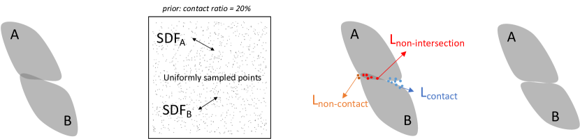
We propose a novel way to enforce topological constraints between 3D objects, with a specific focus on cases like the aforementioned heart ventricles. More specifically, given two 3D objects represented by their deep implicit signed distance functions [19] and a prior indicating a desired contact ratio (%) between them, our goal is to refine them such that they contact each other with that exact ratio and do not intersect. To achieve this, we first uniformly sample a large number of points and compute their signed distances to the two objects. At any given state of the objects, we can estimate the intersection volume by counting the number of random points that fall within both objects. Similarly, the contact ratio can be estimated by evaluating the ratio of points that lie in close proximity to the surfaces of both objects. Based on the prior, we can estimate the expected number of random points that should be in contact with both objects and fine-tune the object’s implicit functions accordingly.
We apply our proposed method to the problem of reconstructing different components of the 3D human heart. Each pair of heart components exhibits a consistent type of topological interaction. They should never intersect and consistently maintain a specific contact ratio, i.e., there should be no inter-penetrations but they should match tightly, without unwarranted gaps. While these constraints are not automatically satisfied when using individual deepSDF [19] to model each component, the results of our method exhibit proper topological interactions and also have lower Chamfer distances than the baseline method. Further, we show that our proposed system can modify a generative implicit hand model to interact with an arbitrary object in a proper manner. Our proposed losses enable the hand model to be re-positioned and its pose optimized to increase the contact ratio while preventing any intersection with the object.
In short, our core contribution is to show that topological interactions between 3D objects can be enforced via uniformly sampled 3D points. In essence, we use the statistics of random-point-object distances to indirectly observe and manipulate the object interaction.
2 Related Work
Image-Based Topological Interaction.
Many 2D segmentation problems involve semantic classes that have some relative topology constraints between them, such as road connectivity over a background or cell nuclei that should be contained within the cytoplasm. Mosinska et al. [17] proposes a topology-aware loss that uses the response of selected filters from a pre-trained VGG19 network. These filters prefer elongated shapes and thus alleviate the broken connection issue. Hu et al. [9] uses a topology loss based on persistent diagrams to help cell segmentation. Other works rely on detecting and penalizing critical pixels for topology interaction between classes, such as Hu [8] and Gupta et al. [4], using homotopy warping and convolutions respectively to find these pixels. However, image and pixel based topology constraints do not lend themselves easily to implicit multi-object 3D reconstruction.
Multi-Object 3D Reconstruction.
Multi-object 3D reconstruction [10, 14] is a fundamental task for scene understanding or generation. The presence of multiple objects poses a different set of challenges compared to single-object reconstruction where objects are usually treated as isolated geometries without considering the scene context, such as object locations and instance-to-instance interactions. For multi-object reconstruction, Mesh R-CNN [3] augments Mask R-CNN [7] with a mesh predictions branch that estimates a 3D mesh for each detected object in an image. Total3DUnderstanding [18] presents a framework that predicts room layout, 3D object bounding boxes, and meshes for all objects in an image based on the known 2D bounding boxes. However, these three methods first detect objects in the 2D image, and then independently produce their 3D shapes with single object reconstruction modules. Liu and Liu [14] propose a system to infer the pose, size, and location of 3D bounding boxes and the 3D shapes of multiple object instances in the scene, which is divided into a grid whose cells are occupied by objects. Irshad et al. [11] recovers objects shape, appearance, and poses using implicit representations, as has become increasingly frequent, e.g., [11, 12, 21, 1].
3D Interaction.
While some works aim to enforce physical plausibility between objects in a scene, e.g., Engelmann et al. [2] that enforces a collision loss between reconstructed objects, most works focus on human-object interactions. Karunratanakul et al. [12] models the grasp between the hand and an object as implicit surfaces and learns to generate new grasps using a VAE, Ye et al. [21] reconstruct from an image the hand-object interaction, and at the same time the object as an implicit surface, and Contact2Grasp [13] learns to synthesize grasps by first predicting a contact map on the object surfaces. Other directions include body-garment interaction, such as DrapeNet [1] with a physically based self-supervision, or human-scene interaction [6]. However, these works primarily focus on interactions between the articulated human body and objects, without incorporating any prior information on how they should interact. In contrast, our approach considers a specific topological prior that needs to be enforced between two objects.
3 Method
Our method refines two 3D implicit objects to ensure their interaction aligns with a topological prior. In this section, we describe our method designed to enforce two conditions: 1) objects should not intersect each other and 2) they contact each other with given percentage surface areas. Different configurations of our method designed for other interactions are included in the supplementary material.
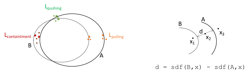
Figure 1 summarizes our proposed method. Given a pair of objects represented by their deep signed distance functions (deep-SDF)[19] and a prior indicating the contact ratio (the percentage of surface areas that should be in contact with the other object), we first compute the signed distances between the two objects and a randomly sampled point cloud. We then select a subset of points that reside in close proximity to the surfaces of both objects, with the number of points determined based on the provided prior. By utilizing these points as anchors, we refine the objects by fine-tuning their deep-SDF to ensure that no points are located inside the surfaces of both objects while simultaneously pulling the object surfaces towards areas that should be in contact.
(a) (b) (c) (d)
3.1 Deep-SDF Preliminary
Implicit surface representations in the form of singed-distance functions [19] have recently emerged as a powerful model to learn continuous representations of 3D shapes. They allow detailed reconstructions of object instances as well as meaningful interpolations between them. A signed distance function of an object is a function that outputs the point’s distance to the closest object surface:
| (1) |
Conventionally, the distance is negative if the point is inside the object and positive otherwise.
In this paper, we focus on the interaction between a pair of objects instances of two categories represented by two deep signed-distance functions and . Here, and are two deep networks approximating SDFs of multiple objects of category and , respectively. The latent vector encodes information for a specific instance of category and the latent for a specific object similarly. Following [19], and are trained on a large set of training instances while at test time, we optimize the latent codes based on the testing instances’ signed distances as well as their interaction prior. For the rest of the paper, we refer to the approximated deep SDF functions and as deep-SDF objects.
3.2 Enforcing Topological Interaction via Random Points
Let us consider explicit meshes of two 3D objects denoted as . The contact ratio of mesh w.r.t. mesh is defined as follows:
| (2) |
where represents the partial surface of object that includes all points within a small distance to object , and refers to the entire surface of object . However, computing this ratio using object meshes is computationally expensive, and further, it is not directly applicable for implicitly represented objects where the object surfaces are not readily available [15]. To overcome this issue, our key observation is that the contact ratio between the two implicit objects can be closely approximated via the signed distances between them to a larger number of uniformly random points. In particular, the contact ratio of a deep-SDF object to another deep-SDF object can be approximated by the following equation:
| (3) |
where is the set of uniformly random points, is a small threshold indicating the “contact” distance, and is the indicator function that returns the value 1 if its statement is true and 0 otherwise. In essence, the contact ratio here is estimated via a stochastic Monte Carlo method by counting the number of points lying close to the surfaces of both objects and the number of points lying close to the surface of one object. Our analysis shows that with a large enough value of , the result obtained from equation 3 closely approximates the contact ratio calculated using explicit meshes in equation 2.
Building on this observation, we propose to refine the topological interaction between two implicit objects by adjusting their distances to a uniformly sampled point cloud. The goal of the adjustment is to ensure the two objects interact with a similar contact ratio as a given prior while having no intersection. Let us consider two deep-SDF objects and with a prior that of surface should be in contact distance with . Here we assume that is given or can be trivially computed from the training set. Given uniformly random points , the number of points that is close to the surface of can be calculated as = . Based on the prior, the expected number of points lying on the contact surface between the two objects should be . Thus, we choose a set of anchor points containing the top points with the smallest distance to among points lying close to the surface of . To prevent the two objects from having a larger contact ratio than the prior, we select a set of anchor points containing all points within a contact distance to both objects while not being in .
To ensure that there is no intersection between two objects, we find all anchor points lying inside both and and push their surfaces to these points via a non-intersection loss function:
| (4) |
where function restricts a given value between an upper and lower bound and are hyper-parameters of our model.
Since and are both negative, this loss function drives the surface of both objects to be pushed toward these anchor points. To enforce a contact ratio of between the two objects, we enforce that all chosen anchor points in need to be within small distances to both objects via a contact loss function:
| (5) |
This loss pushes the surfaces of the two objects closer together. In particular, if and ,i.e., the point lies inside the surface of object , the loss function will increase while decreasing 111In this case, is smaller than or else the two objects would intersect. such that their values closely match. If and , the loss simply pulls the surfaces of both objects to this anchor point.
To prevent the two objects from having a larger contact ratio than the given prior, we push the surface of two objects further away from the anchor points in by a pushing loss function:
| (6) |
The loss function to fine-tune the deep-SDFs of the two objects is:
| (7) |
where is the data reconstruction term that regresses the signed distances[19] and are controlling parameters. During the optimization process, it is important to note that we periodically sample points to ensure they accurately reflect the current state of the object shapes. Further details regarding the loss functions and the optimization algorithm can be found in the supplementary material.
4 Metrics and Experiments
We conduct experiments on the task of 3D heart reconstruction and further demonstrate an application for simulating hands-contacting objects. Following [19], we first train deep SDFs models for different objects on a training set. At test time, we optimize a pair of random latent codes such that the models fit the signed distances to the testing objects’ surfaces.
4.1 Measuring Topological Interaction Similarity via Signed Distance Histogram Distance
Comparing object interactions is non-trivial since it is hard to describe. Current metrics for 3D object reconstruction including the intersection-over-union (IoU) or Chamfer distance, for the most part, do not sufficiently characterize the differences between two interactions. Two interactions can have small individual parts’ chamfer distances while being completely distinct such as contacting versus slightly intersecting. To measure the topological similarities between two interactions, we propose the use of signed distance histogram distances. The histogram is computed by dividing the range of signed distances ( in our paper) into bins and then counting the percentage of surface area that falls into each bin. The histogram considers both the intersection ratio (at bin “<0”) and the contact ratio (the smallest positive bin). In this paper, we set the bin values at since all meshes are rendered to the size of while the signed distances range from -1 to 1. Thus, each pixel corresponds to 0.008 units of distance. The distance between two histograms can be computed by summing the absolute difference at each bin.
4.2 3D Heart Reconstruction
Accurate reconstruction of heart substructures is important in the development of clinical applications. Here we are particularly interested in building a 3D model of the human heart that is topologically correct, reflecting the accurate connectivity between different parts of human hearts.
We experiment on the whole-heart segmentation dataset introduced by Zhuang and Shen [22], which includes 120 whole-heart models with 3D segmentation of various parts of the human heart such as the myocardium of left ventricle (M-LV), left atrium (LA), left ventricle (LV), right atrium (RA), and right ventricle (RV). The dataset is split into 100 training instances and 20 testing instances. We first extract connectivity priors in terms of contact ratios between different components of the heart, i.e., the ratio between the area of the contact surface over the total surface area of each part. We visualize different components of a 3D heart model and the contact ratios between them in Figure 2. In plot 2b, we use the data meshes to measure the contact ratios (i.e., equation 2) while in plot 2c, we measure the contact ratios via the signed distances of the meshes to a random point cloud (following equation 3). The values between the two plots are closely matched, showing that we can use a set of random points to measure the contact ratio between two 3D objects. As can be seen, 87.5% of the LV’s surface is in contact distance with the M-LV’s surface since M-LV is an outer layer covering LV (see Figure 3). These ratios are relatively consistent across different instances. We average these numbers across the whole training set and use them as priors when reconstructing testing instances.
Table 1 summarizes the results of our method in comparison with deepSDF[19] models trained without our proposed losses. We conduct experiments on different pairs of heart components where we focus on pairs with significant contact ratios: 1) M-LV and LV, 2) LA and LV, 3) RA and RV, and 4) M-LV and RV. We report the average intersection ratio (lower is better), contact ratio (closer to the ground truth is better), chamfer distance (lower is better), and signed distance histogram distance (lower is better). As can be seen, our proposed losses improve the 3D reconstruction in all metrics. The reconstructed components do not intersect each other more than 0.1% in all cases while having contact ratios closely approximating the ground truth. Shapes generated from a vanilla deepSDF [19] model significantly intersect each other while having lower contact ratios.
We visualize qualitative samples for two different cases in Figure 3. For each case, we show how the two heart components connect based on the ground truth data (first two columns), the reconstructed 3D meshes using the baseline method DeepSDF, and the reconstructed 3D meshes using our method. The contact surfaces are colored green while the intersecting surfaces are colored red. The contact and intersection ratios are shown next to the plots. The results of our method show no surface intersection between components. We include more results on whole-heart reconstruction in the supplementary material.
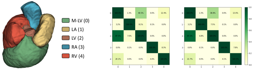
(a) Heart Components (b) Contact ratios (c) Appx. contact ratios
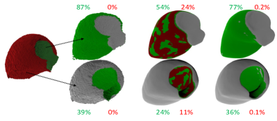
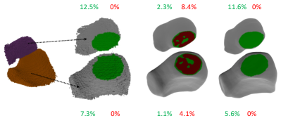
(a) M-LV and LV. (b) RA and RV. The bottom part is rotated to better show the contact areas.
| Intersection (%) | Contact (%) | Chamfer () | SDH Dist. | |||||||
| Dataset | Part | dSDF | Ours | GT | dSDF | Ours | dSDF | Ours | dSDF | Ours |
| MLV-LV | MLV | 24.0 | 0.0 | 38.6 | 11.3 | 35.7 | 1.4 | 1.5 | 1.90 | 0.31 |
| LV | 53.5 | 0.1 | 85.2 | 24.7 | 78.3 | 1.1 | 1.1 | |||
| LA-LV | LA | 6.9 | 0.1 | 13.0 | 3.2 | 9.2 | 1.6 | 1.5 | 0.38 | 0.12 |
| LV | 4.5 | 0.1 | 8.8 | 2.1 | 6.1 | 1.1 | 1.0 | |||
| RA-RV | RA | 7.0 | 0.0 | 12.8 | 2.7 | 8.7 | 1.6 | 1.4 | 0.37 | 0.14 |
| RV | 3.9 | 0.0 | 7.4 | 1.5 | 4.8 | 1.3 | 1.2 | |||
| MLV-RV | RA | 8.0 | 0.0 | 14.0 | 3.9 | 10.9 | 1.4 | 1.3 | 0.12 | 0.04 |
| RV | 13.4 | 0.0 | 22.8 | 6.5 | 18.1 | 1.4 | 1.2 | |||
| Average | 15.2 | 0.0 | 25.3 | 7.0 | 21.5 | 1.4 | 1.3 | 0.7 | 0.2 | |
4.3 Simulating Hand Contacting Objects
The interaction between human hands and objects poses a significant challenge in modeling, given the variability of hand poses and the diversity of objects involved. Simulating and understanding the various ways in which a hand can come into contact with an object is crucial for numerous applications. We demonstrate that our system using random points to drive the interaction between 3D objects can be used to manipulate a generative hand model to increase the contact ratio between the hand and the object while preventing intersection between them.
We first train an auto-decoder model 222The detailed network architecture and training losses are included in the supplementary material. on the SMPL-H dataset [20] containing 1581 hand meshes captured from 31 subjects, each with 51 hand poses (the same for all subjects). Given the trained hand model and a 3D object in space, we are interested in simulating how a hand interacts with the object. To move the hand in space such that it gets closer to the object, we incorporate an affine transformation consisting of a rotation matrix and a translation vector into the deepSDF model:
| (8) |
where is a rotation matrix and is a translation vector. We construct the rotation matrix from the 3 angular parameters such that it does not include any scaling factor. Function allows moving an implicit object freely in space while training on only zero-centered data.
To simulate how a hand interacts with an object, we put the deepSDF model of a hand in random positions in space (defined via the affine parameters ) and the object is at the origin. The latent code is initialized as a random latent code from a random training pose. We set a fixed contact ratio prior for hand and object at , i.e., 20% of the hand surface should be in contact distance. However, we must note that finding a realistic hand pose satisfying the exact prior contact ratio is not possible with the generative deepSDF hand model [12] due to the limited training data. Our system, hence, mainly aims to establish hand-object contact while preventing the intersection between them. In fact, our model can strictly enforce a specific contact ratio between the hand and the object but it results in unrealistic hand surfaces.
Table 2 summarizes the results of our proposed method testing on 10 objects from the HO3D dataset [5]. We average over 10 runs for each object. To evaluate the hand-object interaction, we measure the intersection ratio (%): the ratio between the surface area of the hand that intersects the object over the surface area of the hand; and the contact ratio (%) between the hand and the object. Note that the object can intersect the hand in its initial starting position. Our losses, optimizing over the values of , re-position the hand as well as modify the hand pose to lower the intersection while increasing the contact ratios in all cases.
| Intersection(%) | Contact(%) | |||||
|---|---|---|---|---|---|---|
| Item | Init. | Aff. | Aff. + Latent | Init. | Aff. | Aff. + Latent |
| 11-Banana | 6.8 | 3.7 | 1.1 | 2.1 | 14.1 | 15.8 |
| 24-Bowl | 4.9 | 4.2 | 0.4 | 1.5 | 8.6 | 10.7 |
| 04-Sug.box | 4.9 | 1.1 | 0.4 | 1.3 | 6.8 | 7.2 |
| 06-M.bottle | 4.3 | 1.1 | 0.8 | 1.4 | 8.4 | 9.4 |
| 35-Drill | 8.4 | 3.3 | 0.5 | 2.4 | 4.8 | 7.0 |
| 37-Scissors | 4.0 | 2.5 | 0.9 | 1.2 | 15.9 | 18.2 |
| 61-FoamBrick | 8.4 | 5.3 | 0.7 | 2.7 | 14.2 | 17.5 |
| 25-Mug | 3.8 | 2.8 | 0.4 | 1.2 | 9.3 | 11.2 |
| 03-C.box | 10.9 | 3.8 | 0.4 | 2.4 | 2.9 | 4.1 |
| 52-L.clamp | 3.6 | 1.2 | 0.4 | 1.4 | 6.9 | 8.0 |
| Mean | 6.0 | 2.8 | 0.6 | 1.7 | 9.0 | 10.7 |
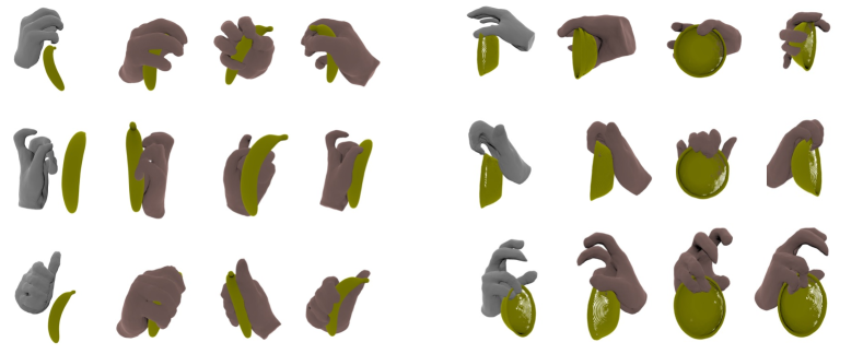
Here we do not aim to generate realistic hand grasps but simply force the hand to interact with objects. In many cases, it simply results in the object resting on the hand. Generating realistic hand-grasping objects is a challenging and active research problem on its own. Nevertheless, our system can generate various feasible and realistic hand-object interactions, as can be seen in Figure 4. For each row, we show the original positions of the hand and object in space, and then three views of the optimized hand. Please see the supplementary material for more results.
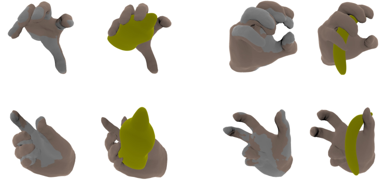
In Figure 5, we visualize how our losses optimize hand shapes to have better “grips” on objects. For each pair, we show the original hand pose (colored in gray) overlaid by the optimized hand pose (colored in the skin color), and how the optimized hand interacts with the object. The hand model moves the fingers to positions that increase the contact areas (top row) or to positions that do not intersect the objects (bottom row). It shows that our losses can serve as supervision signals to drive generative shape models in meaningful manners.
(a) Banana (b) Bowl
5 Limitations
There are limitations of our work that can be interesting directions for future work. Computing signed distances from object surfaces to a large number of points can be computationally expensive and might not be trivially applicable to other kinds of surface representations. Here we only consider a fixed topological constraint for a given pair of classes while in practice, they can be in a more dynamic form and can be even hard to estimate. Further, we must note that we indirectly manipulate the object surfaces via stochastic Monte Carlo estimation. There is no guarantee about the correctness of the topological interactions since at no point do we directly measure them.
6 Conclusions
We discuss the problem of 3D multiple object reconstruction where a topological prior is given. The prior implies the interaction between objects, which can be in the form of contact ratio. Our key observation is that the object interaction can be observed via a stochastic estimation method by uniformly sampling a large number of points and computing distances between them to the objects. Further, the interaction between objects can be refined by choosing a set of points as anchors to modify the object surfaces. Experiments on 3D heart reconstruction and hand-object interaction demonstrate the effectiveness of our proposed method.
In general, our work highlights the importance of incorporating topological priors in 3D multiple-object reconstructions. By leveraging stochastic sampling, we enable accurate modeling of object interactions which is crucial in various domains. For example, topological priors can be applied to the reconstruction of skeletal structures since they are typically positioned in fixed relationships with each other. In robotics, we can incorporate topological priors that define the expected contact patterns and containment relationships to enhance the robot’s ability to manipulate objects accurately and with minimal collisions.
Appendix A Enforcing Containment with Fixed Distances between Classes
In the main paper, we have presented our system to enforce two 3D objects to have a specific contact ratio. In general, our proposed concept of using random points to observe and manipulate the topological interaction between objects can be used for various types of topological constraints. In this section, we describe how we can enforce a containment relationship between two objects (one is completely inside the other) while also maintaining their surface distance within a specific range. This is particularly useful for modeling 3D objects with designated “thickness” attributes where the inner and outer layers are viewed as separate objects with the aforementioned topological interaction.
Let us consider two deep-SDF objects and . Our objective is to ensure that all points on the surface of are located within the interior of while the distance between them,i.e., the thickness of the wall, is always in the range . We assume that and are given or can be easily computed from the training data.
To achieve this, we begin by uniformly sampling random points, denoted as . From this set, we select a set of points, , containing points that are in proximity (based on a predefined small threshold) to the surface of either object.
To ensure that is strictly located inside , we can minimize the following containment loss that penalizes points located outside but inside :
| (9) |
where function restricts a given value between an upper and lower bound and are hyper-parameters of our model. This loss drives the surfaces of both and toward the anchor points (see Fig.6a).
To ensure that the distance between two objects is in the range , we first find anchor points lying on the areas where the local surface distance between the two objects is smaller than or larger than . Given a random point that either locates ① inside both objects, ② between the two objects, or ③ outside both objects, we can estimate the length of a line segment lying between a pair of two objects and passing through as follow:
| (10) |
Based on this method to measure local surface distances, we select a set of points lying in areas where the distance between two objects is smaller than and adjust the object surfaces by minimizing the following loss function, which increases the margin between the two objects:
| (11) |
Similarly, we enforce a loss function with an opposite effect for points lying on areas where the distance between the two objects is larger than :
| (12) |
The loss function to fine-tune the deep-SDFs of the two objects is:
| (13) |
where is the data reconstruction term that regresses the signed distances[19] and are controlling parameters.
(a) (b)
A.1 Experiment
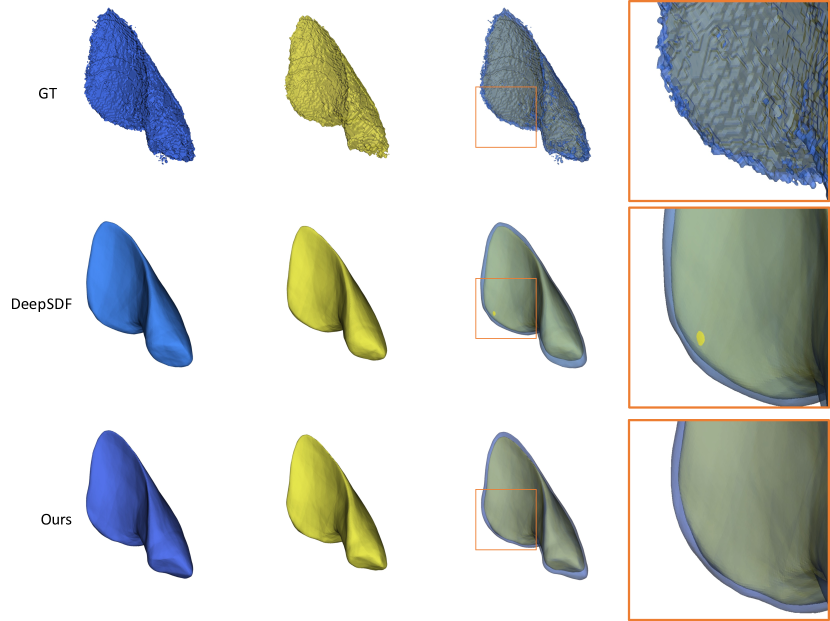
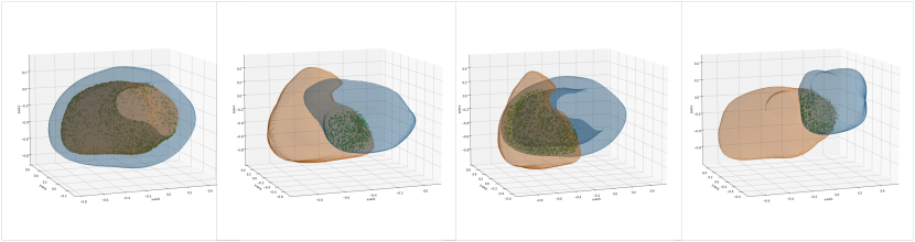
To demonstrate the effectiveness of this method, we conduct an experiment on reconstructing the pseudo inner walls of different heart components. We start from the occupancy matrix of each heart component and apply a 3D erosion operation to obtain an inner structure of each part. In this context, we consider the original structure as the “outer layer” and the eroded one as the “inner layer”, which are colored blue and yellow respectively in Fig. 7.
We use our proposed method to simultaneously model the outer and inner structures. In this experiment, we assume are given (all vertex coordinates are scaled to before training, is equivalent to pixels when rendering objects at size ). Note that these values are specific to this proof-of-concept experiment and can be directly inferred from the erosion kernel.
For each pair of outer-inner objects, we sample 20000 points and their SDF values. We optimize the latent codes of two deep SDF models to fit these values. We compare a basic baseline trained with just the data term and our proposed method trained with the aforementioned loss functions. To evaluate the effectiveness of the methods, we measure the percentage of the inner object surface that violates the imposed topological constraints for each reconstructed outer-inner object pair. The summarized results are presented in Table 3. The baseline deepSDF model exhibits a violation rate of around 2-3% on the inner object surface, while our proposed method shows minimal violations.
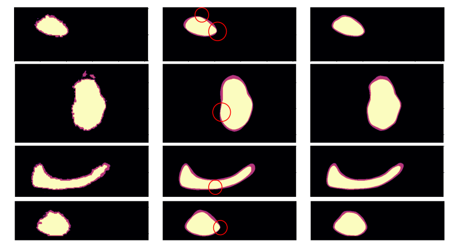
We visualize an example in Fig.7. Both the baseline deepSDF [19] and our method can reconstruct the overall shapes of objects. However, in the last column, we highlight an area where the baseline deepSDF model exhibits a violation by reconstructing a partial surface of the inner object outside the outer object. Our method shows no violation. Additionally, we provide several examples of 2D slices from different objects in Fig.8. These examples demonstrate various cases where the baseline deepSDF model fails to generate objects that satisfy the imposed constraints. Our method show no violation in all cases.
| Component | Violation (% area) | Violation (N.o. vertexes) | N.o. vertexes | ||
|---|---|---|---|---|---|
| deepSDF | Ours | deepSDF | Ours | ||
| MLV | 3.51 | 0.11 | 4638.94 | 145.80 | 132104.5 |
| LA | 2.66 | 0.00 | 1170.26 | 0.00 | 43932.0 |
| LV | 3.36 | 0.00 | 2020.36 | 0.00 | 60126.6 |
| RA | 3.49 | 0.15 | 1267.76 | 55.66 | 36288.4 |
| RV | 2.31 | 0.02 | 1547.81 | 16.59 | 67140.2 |
Outer Inner Outer& Inner Zoom-in Crop
Appendix B More Details on Network Architecture and Optimization
In all of our experiments, we adopt the auto-decoder framework introduced in deepSDF [19]. The decoder network consists of 6 fully connected layers, each with 256 dimensions and ReLU activation. We utilize a Tanh activation function as the final layer to output the signed distance function (SDF) values. Layer normalization [ba2016layer] is applied to normalize intermediate outputs after each layer. The auto-decoder is trained for 20,000 epochs using the Adam optimizer [kingma2014adam].
To prepare data, we normalize the vertices of each mesh to the range of [-1,1]. For training, we sample 440,000 spatial points to compute SDF values for each shape. The ratio of points near the object’s surface to random points is set to 10:1. Throughout the optimization process, we sample 22,000 spatial points to compute SDF values for each shape. The baseline deepSDF models are trained for 20,000 epochs. It is important to note that while we use as input a small number of spatial points and their SDF values, the core idea of our method is independent of the input representation. Alternative approaches, such as training a 3D segmentation model to generate initial object meshes or training an encoder-decoder system to regress latent codes before refining them with our proposed method, can also be employed.
To refine the topological interaction, we uniformly sample 1M random points after every 200 iterations for heart component reconstruction and after every 20 iterations for hand-object reconstruction. Computing SDF distances from these points to deepSDF models requires a single feed-forward pass through each model and obtaining anchor points takes 0.1 seconds in total. For a pair of testing objects, we optimize the system for 2000 iterations, which takes 24 seconds for an NVIDIA A100 GPU. The baseline deepSDF takes 12 seconds.
We experimentally set the parameters to (0.0001,0.0001,0.0001). The parameters in eq. (7) and in eq. (13) are both set to .
Appendix C Signed Distance Histogram Distance
To measure the topological similarities between two interactions, we propose the use of signed distance histogram distances. The histogram is computed by dividing the range of signed distances ( in our paper) into bins and then counting the percentage of surface area that falls into each bin. The histogram considers both the intersection ratio (at bin “<0”) and the contact ratio (the smallest positive bin). We set the bin values at since all meshes are rendered to the size of while the signed distances range from -1 to 1.
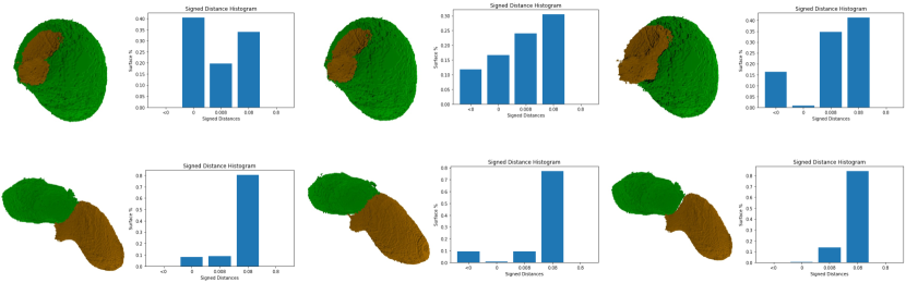
We visualize a few histograms computed between human heart components in Fig.9. In all cases, the histogram is computed for signed distances from the “green” object to the “orange” object. In the first column, we visualize the histograms computed for pairs of ground-truth objects. We then translate the “green” objects by a small offset of +3 and -3 pixels along the x-axis, which results in the middle and last columns, respectively. As can be seen, moving the objects by small offsets significantly change the topological interactions between them, e.g., from contact with a large ratio to significantly intersecting. These variations in interactions are effectively captured and reflected in the computed histograms.
Appendix D Hand contacting objects
We use our proposed losses with random anchor points to enforce a hand model to contact an arbitrary object. We first uniformly random 1 million spatial points and compute the signed distances from them to the deepSDF hand and object models. We then choose the top of points lying close to the surface of the hand and enforce these points to be in contact distance with the object. We vary the value of (10/20/30) as well as randomly initialize the pose, position, and rotating angle of the hand to obtain different hand-object interactions. It is important to note that not all latent embeddings result in realistic hands due to the limited training data. In some cases, the generated hand models may not appear visually realistic, as depicted in Fig. 10.

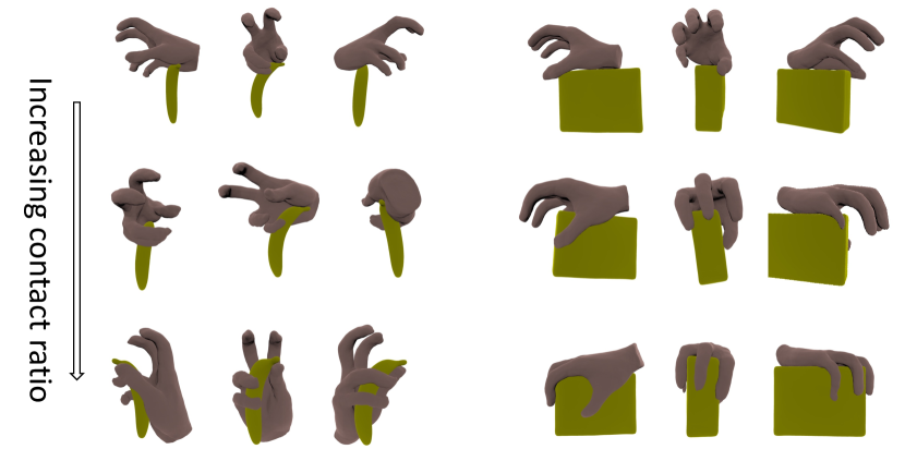
Different values of lead to different interactions between the hand and the object. As the value of increases, it encourages the hand model to find a position and pose that results in a larger contact ratio with the object. This effect is demonstrated in Figure 11 for two different objects. In each case, the model is initialized from the same pose and starting position, but as increases, the hand "grasps" the objects differently, with increasing contact ratios from the top to bottom rows.
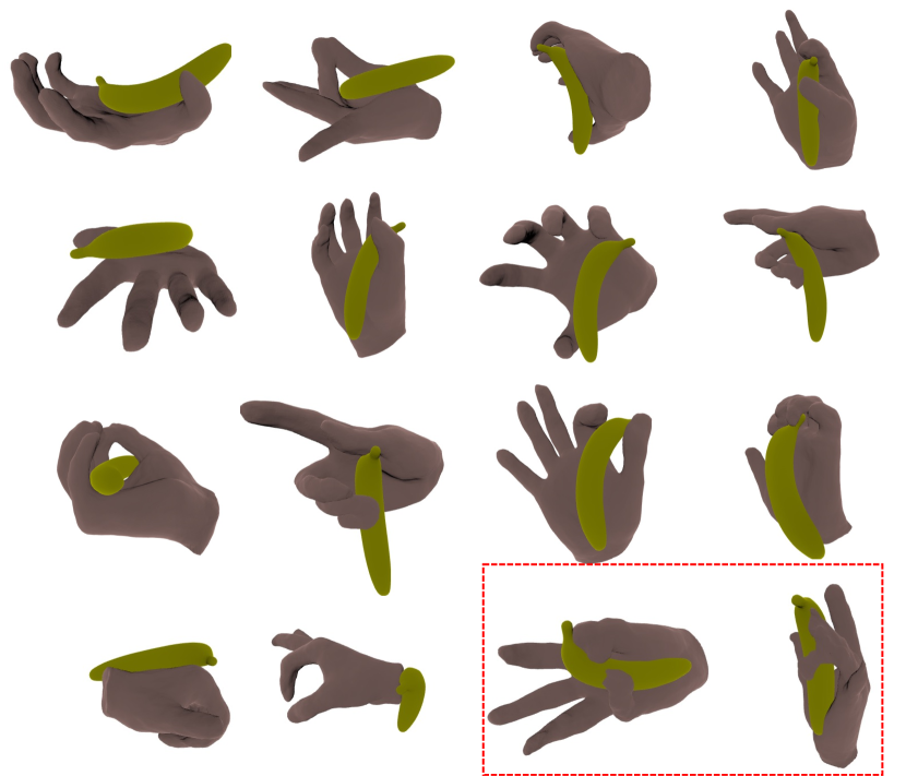
Our method enables the generation of diverse interactions between the hand model and any arbitrary 3D object, as illustrated in Figure 12. It is important to note that we do not explicitly control the location of the contact. Instead, the hand model autonomously determines where the contact occurs based on the optimization process. To avoid generating unrealistic hand shapes, such as those highlighted in the red bounding box, we utilize a small learning rate (1e-6) for the latent code of the hand model. This helps to maintain the overall realism and stability of the generated hand-object interactions.
Appendix E Visualizing Anchor Points
We visualize anchor points used in our method for refining interactions between different pairs of heart components. We choose among randomly sampled points ones that are close to the surfaces of both objects where the numbers of points are determined via a prior contact ratio. As can be seen, those anchor points are distributed evenly on the contact surface, allowing us to refine the interactions between the two objects.
(a) MLV- LV (b) RA- RV (c) MLV- RV (d) LA-MLV
References
- De Luigi et al. [2023] Luca De Luigi, Ren Li, Benoit Guillard, Mathieu Salzmann, and Pascal Fua. DrapeNet: Garment Generation and Self-Supervised Draping. In Proceedings of the IEEE/CVF Conference on Computer Vision and Pattern Recognition, 2023.
- Engelmann et al. [2020] Francis Engelmann, Konstantinos Rematas, B. Leibe, and Vittorio Ferrari. From points to multi-object 3d reconstruction. 2021 IEEE/CVF Conference on Computer Vision and Pattern Recognition (CVPR), pages 4586–4595, 2020.
- Gkioxari et al. [2019] G. Gkioxari, J. Johnson, and J. Malik. Mesh r-cnn. In 2019 IEEE/CVF International Conference on Computer Vision (ICCV), pages 9784–9794, 2019.
- Gupta et al. [2022] Saumya Gupta, Xiaoling Hu, James Kaan, Michael Jin, Mutshipay Mpoy, Katherine Chung, Gagandeep Singh, Mary Saltz, Tahsin Kurc, Joel Saltz, et al. Learning topological interactions for multi-class medical image segmentation. In ECCV, pages 701–718. Springer, 2022.
- Hampali et al. [2020] Shreyas Hampali, Mahdi Rad, Markus Oberweger, and Vincent Lepetit. Honnotate: A method for 3d annotation of hand and object poses. In CVPR, 2020.
- Hassan et al. [2020] Mohamed Hassan, Partha Ghosh, J. Tesch, Dimitrios Tzionas, and Michael J. Black. Populating 3d scenes by learning human-scene interaction. 2021 IEEE/CVF Conference on Computer Vision and Pattern Recognition (CVPR), pages 14703–14713, 2020.
- He et al. [2017] Kaiming He, Georgia Gkioxari, Piotr Dollar, and Ross Girshick. Mask r-cnn. In Proceedings of the IEEE International Conference on Computer Vision (ICCV), Oct 2017.
- Hu [2021] Xiaoling Hu. Structure-aware image segmentation with homotopy warping. 2021.
- Hu et al. [2019] Xiaoling Hu, Fuxin Li, Dimitris Samaras, and Chao Chen. Topology-preserving deep image segmentation. In H. Wallach, H. Larochelle, A. Beygelzimer, F. d'Alché-Buc, E. Fox, and R. Garnett, editors, Advances in Neural Information Processing Systems, volume 32. Curran Associates, Inc., 2019. URL https://proceedings.neurips.cc/paper_files/paper/2019/file/2d95666e2649fcfc6e3af75e09f5adb9-Paper.pdf.
- Irshad et al. [2022a] Muhammad Zubair Irshad, Thomas Kollar, Michael Laskey, Kevin Stone, and Zsolt Kira. Centersnap: Single-shot multi-object 3d shape reconstruction and categorical 6d pose and size estimation. 2022 International Conference on Robotics and Automation (ICRA), pages 10632–10640, 2022a.
- Irshad et al. [2022b] Muhammad Zubair Irshad, Sergey Zakharov, Rares Ambrus, Thomas Kollar, Zsolt Kira, and Adrien Gaidon. Shapo: Implicit representations for multi object shape appearance and pose optimization. 2022b. URL https://arxiv.org/abs/2207.13691.
- Karunratanakul et al. [2020] Korrawe Karunratanakul, Jinlong Yang, Yan Zhang, Michael J Black, Krikamol Muandet, and Siyu Tang. Grasping field: Learning implicit representations for human grasps. In 2020 International Conference on 3D Vision (3DV), pages 333–344. IEEE, 2020.
- Li et al. [2023] Haoming Li, Xinzhuo Lin, Yang Zhou, Xiang Li, Yuchi Huo, Jiming Chen, and Qi Ye. Contact2grasp: 3d grasp synthesis via hand-object contact constraint, 2023.
- Liu and Liu [2021] Feng Liu and Xiaoming Liu. Voxel-based 3d detection and reconstruction of multiple objects from a single image. In Neural Information Processing Systems, 2021.
- Lorensen and Cline [1987] William E. Lorensen and Harvey E. Cline. Marching cubes: A high resolution 3d surface construction algorithm. Proceedings of the 14th annual conference on Computer graphics and interactive techniques, 1987.
- Ma et al. [2020] Qianli Ma, Jinlong Yang, Anurag Ranjan, Sergi Pujades, Gerard Pons-Moll, Siyu Tang, and Michael J. Black. Learning to dress 3d people in generative clothing. In Proceedings of the IEEE/CVF Conference on Computer Vision and Pattern Recognition (CVPR), June 2020.
- Mosinska et al. [2017] Agata Mosinska, Pablo Márquez-Neila, Mateusz Koziński, and P. Fua. Beyond the pixel-wise loss for topology-aware delineation. 2018 IEEE/CVF Conference on Computer Vision and Pattern Recognition, pages 3136–3145, 2017.
- Nie et al. [2020] Yinyu Nie, Xiaoguang Han, Shihui Guo, Yujian Zheng, Jian Chang, and Jian Jun Zhang. Total3dunderstanding: Joint layout, object pose and mesh reconstruction for indoor scenes from a single image. In IEEE/CVF Conference on Computer Vision and Pattern Recognition (CVPR), June 2020.
- Park et al. [2019] Jeong Joon Park, Peter R. Florence, Julian Straub, Richard A. Newcombe, and S. Lovegrove. Deepsdf: Learning continuous signed distance functions for shape representation. 2019 IEEE/CVF Conference on Computer Vision and Pattern Recognition (CVPR), pages 165–174, 2019.
- Romero et al. [2017] Javier Romero, Dimitrios Tzionas, and Michael J. Black. Embodied hands. ACM Transactions on Graphics (TOG), 36:1 – 17, 2017.
- Ye et al. [2022] Yufei Ye, Abhinav Kumar Gupta, and Shubham Tulsiani. What’s in your hands? 3d reconstruction of generic objects in hands. 2022 IEEE/CVF Conference on Computer Vision and Pattern Recognition (CVPR), pages 3885–3895, 2022.
- Zhuang and Shen [2016] Xiahai Zhuang and Juan Shen. Multi-scale patch and multi-modality atlases for whole heart segmentation of mri. Medical image analysis, 31:77–87, 2016.