Role of isotropic and anisotropic Dzyaloshinskii-Moriya interaction on skyrmions, merons and antiskyrmions in the symmetric system
Abstract
The lattice Hamiltonian with the presence of a chiral magnetic isotropic Dzyaloshinskii-Moriya interaction (DMI) in a square and hexagonal lattice is numerically solved to give the full phase diagram consisting of skyrmions and merons in different parameter planes. The phase diagram provides the actual regions of analytically unresolved asymmetric skyrmions and merons, and it is found that these regions are substantially larger than those of symmetric skyrmions and merons. With magnetic field, a change from meron or spin spiral to skyrmion is seen. The complete phase diagram for the symmetric system with anisotropic DMI is drawn and it is shown that this DMI helps to change the spin spiral propagation direction. Finally, the well-defined region of a thermodynamically stable antiskyrmion phase in the symmetric system is shown.
The Dzyaloshinskii-Moriya interaction [1, 2, 3], an asymmetric exchange interaction, plays an important role in stabilizing the noncollinear magnetic structure in broken inversion symmetric systems. The spin spiral (SS), whose length scale [4, 5, 6, 7] is mostly created by DMI and symmetric exchange interactions, is a common noncollinear ground state of a chiral magnet. This ground state transforms into a number of interesting topologically protected small-scale spin textures, including skyrmions [8, 9, 10, 11, 12, 13, 14] and merons [15, 16], with the aid of magnetic fields, magnetic anisotropy, and higher order frustrated exchange interactions. These spin textures are classified into two types based on crystal symmetry: Neel type for symmetric and Block type for symmetric systems [4, 5]. Whereas, the symmetric system [6] supports antiskyrmions [17] and antimerons [18]. Due to their tiny size [19, 20], topological stability[4, 5], and stability over a broad range of parameter spaces [7, 21, 6, 22, 23] including magnetic field, anisotropy, and DMI, all of these topological non-trivial phases have had a positive impact on the field of spintronics[24, 25, 26, 27, 28, 29].
We have a semi-analytic theory [5, 7, 6] for singly symmetric skyrmions in a ferromagnetic background. However, we still have no analytical solution for experimentally observed asymmetric skyrmions [30, 31, 32, 33] in the presence of easy plane anisotropy. Since the topological number remains the same [34, 7], asymmetric skyrmions have the same topological properties as symmetric skyrmions, such as the Hall effect [35]. Asymmetric merons such as asymmetric skyrmions have been observed experimentally [15, 36, 37, 38] in regions of easy plane anisotropy. Even merons always appear in lattice form [15, 16, 7]. Continuum model-based analytical solutions, however, are more suitable for single symmetric skyrmions and merons. As a result, we are unable to construct precise phase diagrams for the lattice skyrmions, asymmetric skyrmions, symmetric merons and asymmetric merons using the continuum model. In this article, I describe the full phase diagram by minimizing the lattice Hamiltonian in presence of isotropic DMI using Monte Carlo (MC) simulations with periodic boundary conditions on both square and hexagonal lattices. These phase diagrams depict a transition from SS skyrmions (lattice skyrmion, isolated skyrmion) polar ferromagnet in the easy-axis anisotropy limit and from merons skyrmions in the easy-plane anisotropy limit, all of which have already been observed experimentally [12, 13, 25, 14]. These phase diagrams also demonstrate that asymmetric skyrmions and asymmetric merons have significantly wider regions in the parameter space than symmetric skyrmions and symmetric merons.
The orthogonal coefficients of an anisotropic DMI are different. Heide et al. [39] predicted such DMI in 2Fe/W(100) films using first-principles calculations. It has been observed experimentally in an ultrathin epitaxial Au/Co/W(110) films [40], CoFeB(211)/Pt(110) films [41]. Shibata et al. [42] showed that the anisotropy of bulk DMI causes mechanical strain, which produces an anisotropic skyrmion. We already know that anisotropic DMI is direction dependant, and this strain aids in changing the spin configuration. This DMI can also alter the spin orientation of the skyrmions in a certain manner, leading to the eventual emergence of an antiskyrmions in symmetric system. Hoffmann et al. [43] have first observed antiskyrmions in (110)-oriented films with symmetric systems. Although, we generally know skyrmions appears in symmetric systems. We have a theoretical prediction [7] of antiskyrmion stabilization in symmetric systems. However, neither this skyrmion nor the antiskyrmion is symmetric about their center. Consequently, there are no analytical solutions and phase diagrams for these topological phases. Here, I first demonstrate through MC simulations how the anisotropic DMI promotes the skyrmion to antiskyrmion transition in the symmetric system before illuminating the full phase diagram for this DMI.
I Hamiltonian and Methods
The ferromagnetic Heisenberg spin Hamiltonian in the presence of an easy axis magnetic field can be written as
| (1) |
where is the unit vector of the magnetization at sites. The first term is the isotropic exchange interaction with nearest-neighbor coupling constant, . Second term, is an antisymmetric spin orbit interaction, known as Dzyaloshinskii-Moriya interaction [1]. The direction of the DMI vectoer depends on the crystal symmetries. is proportional to for , and for symmetries systems respectively. Here, is unit vector from to sites. The amplitude of DMI vector () is proportional to interaction strength between spin and orbit. Here, is isotropic. is the coefficient of the magnetic anisotropy. It is positive for easy-plane anisotropy and negative for easy-axis anisotropy. is the effective magnetic field perpendicular to the plane of the systems. The last two terms in Eq. (1) determine the direction of the ferromagnet [22, 7]. When , all spins align parallel to and form a polar ferromagnet phase. For , the direction of magnetization depends on the anisotropy and the magnetic field strength. Easy-plane anisotropy forces all spins to lie in the plane, and the magnetic field forces the spins to lie perpendicular to the plane. Consequently all spins make an angle with the direction of . This configuration is known as tilted ferromagnet.
The Hamiltonian given in Eq. (1) is minimised on both the square lattice and the hexagonal lattice using a MC simulation based on the conventional Metropolis algorithm [44, 45] with periodic boundary conditions. Hamiltonian has many local minima or metastable state for a given parameters. To avoid these metastable states and locate the actual thermodynamic ground state, conventional simulated annealing techniques with MC are employed. The MC simulation begins with a random initial spin configuration at a high temperature. The temperature is then steadily lowered using the formula , with an MC simulation being run at each stage. The initial spin configuration in the MC simulation is derived from the outcome of the preceding step after the first annealing loop has been completed. Repeat the same procedure until my final temperature reaches a very low value ( close to zero). The simulation parameters used in my numerical calculations are: total number of steps in annealing method , initial temperature , final temperature , , and MC steps . is utilized to measure all energy-related parameters such as , and , while , the lattice constant, is used to scale length. is chosen to construct the phase diagram in the plane. This value of DMI supports a SS with periodicity close to . We know that the periodicity of SS in is about [46]. So, the chosen value of DMI belongs to real materials. All these MCs are performed mesh, but the mesh size is increased to for some important results (mostly at phase boundaries). My simulation always treats as 1.
I.1 Numerical Results and Phase Diagrams in Symmetric System
The Hamiltonian (1) has only three parameters, namely , and because is used to scale all energy parameters. We only have the , , and planes for the phase diagram. The article is organized as follows: i begin by showing the whole phase diagram for the symmetric system with isotropic DMI on a square and a hexagonal lattice of different parameter planes. The numerical outcomes for the symmetric system in plane are later explained. Finally, in the presence of anisotropic DMI, numerical results and an entire phase diagram are displayed for the symmetric system.
The final output of the MC gives a spin configuration of the system for a given parameter. To identify the phase that this spin configuration supports, we need to use some distinct properties: local magnetization , average magnetization , local chirality , and total chirality , local spin asymmetric parameter , where N is the number of lattice sites. gives information about symmetry with respect to its center. Chirality helps distinguish between topologically trivial and nontrivial phases. A detailed description of these above parameters for different phases is given in Ref. [21]. These characteristic variables are used to draw phase boundaries in all phase diagrams.
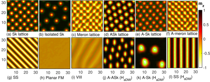
The complete phase diagram for a square lattice in the plane at is shown in Fig. (1a). The large magnetic field transforms the system into the ferromagnetic (FM) phase (Phase-1). In opposite limit, a weak magnetic field causes the spins to form a spin spiral (SS) phase (phase-II). Here, SS propagates along the direction because the sign of the DMI vector is taken positive. These two phases, SS and FM, are topologically trivial and emerge at extreme magnetic field values. Now increasing the magnetic field in the SS phase in the easy-plane anisotropy region. At this stage, all spins begin to experience an additional force in the presence of a magnetic field. The magnetic field seeks to align all of the spins in the field’s direction. DMI, however, aims to provide a finite rotation between the spins. These interactions work together to stabilize a skyrmion. At low field ranges, the skyrmion and spin spiral appear together in what is known as a mixed phase (Phase-III). As the magnetic field increases, the number of spin spirals decreases. Because of this, we’ve reached a point where there are only skyrmions in the system. In this case, the separation between any two skyrmions remains the same and forms a lattice known as skyrmion lattice (phase-IV). The magnetic field increases the spacing between the skyrmions. As a result, fewer skyrmions exist in a given lattice shape and they are also smaller in size. These small-sized skyrmions are randomly distributed in what is called the isolated skyrmion phase (phase-V). The decrease in size of the skyrmions with magnetic field has already been predicted theoretically [7] and observed experimentally [47]. The area of phase-V is much smaller than the phase-IV. Finally for a slight increase in the magnetic field we reach the FM phase. The spin configurations of skyrmion lattice phase and isolated skyrmion phase are shown in figures (2a) and (2b), respectively. We can see that there is a transition from SS to skyrmion to FM with magnetic field which has already been observed experimentally [12, 13, 25, 14].
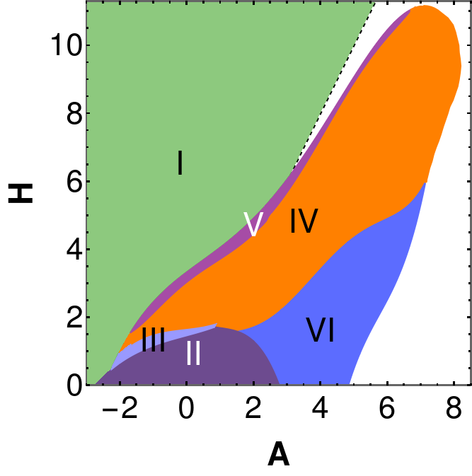
The phase diagram at is interesting because there are no analytical solutions for the asymmetric skyrmions and asymmetric merons in this region. Figure (1a) shows the corresponding phase diagram. We observed both skyrmions and SS phases here, similar to negative anisotropy. Here for all phases, indicating that these skyrmions are not symmetric about their center called asymmetric skyrmions. This result is consistent with analytical predictions [7]. The phase space region of these skyrmions is larger in this case than it is in the case, which is a second crucial fact. Given the wide spectrum of asymmetric skyrmion, this is crucial in application. Spin configuration of a asymmetric skyrmion is shown in figure (2e).
Apart from the existing phases described in the above paragraph, there is another interesting phase which is also topologically non-trivial known as the meron phase (phase-VI). This phase lies below the skyrmion-lattice phase. Like skyrmions, merons are not symmetrical about their center in regions known as asymmetric merons. Spin configuration of asymmetric merons is shown in figure (2f). However, at the merons are formed in the background of planar ferromagnet and are symmetric about their center. Figure (1a) shows that is the range of anisotropy for symmetric merons at . Both types of merons appear in lattice shapes that are consistent with theoretical predictions [15, 16, 7]. This result is new and interesting not only because it is challenging to estimate the potential meron region using continuum models, but also because these results are crucial for practical applications. Phases in the white area in Fig. (1a) are difficult to identify because this region may contain some conical phases and tilted ferromagnet.
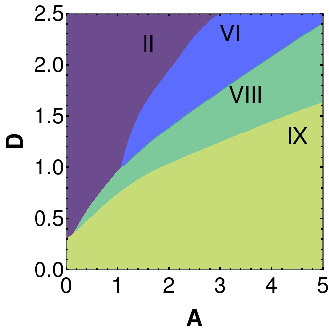
Fig. (1b) shows the full phase diagram in the plane for a better understanding of a symmetric meron. The phase region of symmetric merons increases with both DMI and magnetic anisotropy. This phase diagram also suggests that we need a DMI value close to the exchange interaction strength to stabilize symmetric merons in the absence of a magnetic field. Which indicates that the system should have strong spin-orbit coupling to support symmetric merons. The planar ferromagnetic phase (phase IX) is observed with large anisotropy. An unknown phase (phase VIII) is noticed between merons and planar ferromagnetic phases. The spin configuration of these phases are shown in Fig. (2).
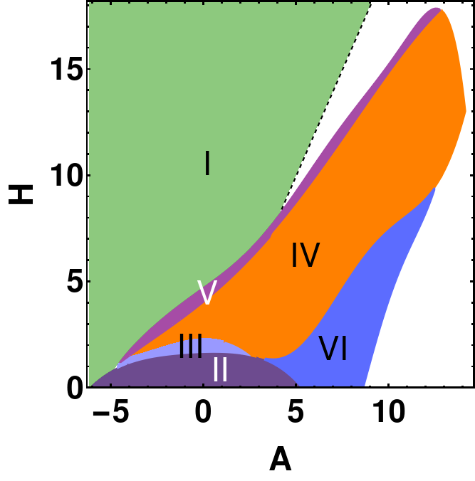
The full phase diagram for the hexagonal lattice is shown in figure (1c). The order and appearance of the phases in the phase diagram are almost the same as in the square lattice phase diagram. However, in the hexagonal case the boundaries of each phase are slightly larger. In other words, each axis of our phase diagram has an additional scaling factor. Here, I consider to be the lattice spacing for the hexagonal lattice (where is the lattice spacing for the square lattice). This additional scaling factor of the phase diagram is due to this lattice spacing.
I.2 Antiskyrmion in Symmetric System
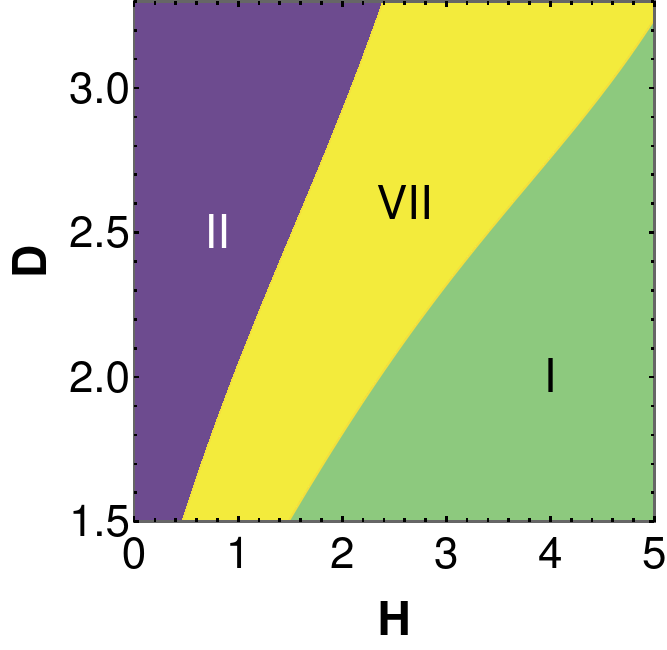
The same numerical method is used to minimize the lattice Hamiltonian (1) in symmetric systems for square lattice. Here the phase diagram is similar to the symmetric system, but the symmetric system has antiskyrmions instead of skyrmions. Since the results are the same, we have calculated the phase diagram in a different plane () for the systems. Fig. (1d) shows that the antiskyrmions phase (phase-VII) regions increase with increasing DMI and magnetic field. Spin configuration of an antiskyrmion is shown in Fig. (2d).
II Antiskyrmion in Symmetric System with Anisotropic DMI
The following form of anisotropic DMI () is considered in the lattice Hamiltonian:
| (2) |
where is a positive number and represents the strength of the anisotropic DMI. The DMI becomes isotropic when . Anisotropic DMI refers to the fact that the DMI’s amplitude in the and directions differ. Here, and are, in the case of an isotropic DMI vector, the and components, respectively. The introductory section has already described how this term is expressed for several symmetric systems. In Eq. (2), the same amount of anisotropy added to the component of is subtracted from the component.
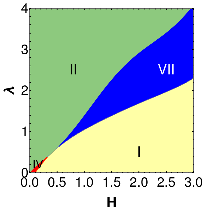
Here, my attention is solely on symmetric system. It is obvious that all skyrmions and merons will be asymmetric about their centres because our DMI is asymmetric in nature. The entire phase diagram at is displayed in Fig. (3) in the plane. The SS phase (phase II) manifests at large anisotropic DMI or large , as expected. The spin configuration of SS phase in this instance differs from the spin configuration of SS phase in isotropic DMI (Fig. (2l) ). For and SS propagates along direction whereas SS in isotropic DMI always propagates along -direction (Because the isotropic DMI vector is assumed to be a positive quantity). This result demonstrates that we can continually modify the SS phase propagation direction by utilising . In the other limit, a ferromagnetic phase (I-phase) is observed at very low and large . Skyrmions (phase-IV) are observed in a small region with low magnetic field and low . These skyrmions are asymmetrical and extended in the direction. For any , the component of is smaller than the component. It is known that the radii [7, 6] of skyrmions and merons depend inversely on the DMI. Thus, the extension of the skyrmions border along the direction seen in our simulations is also supported by the theoretical realization. Fig. (2k) depicts the spin arrangement of these asymmetric skyrmions. Finally, for medium to high values of and , the phase with the greatest interest (phase-IV) is observed. It is an antiskyrmion according to all investigations including topological number, spin configuration and chirality. This antiskyrmion is also not symmetric, known as asymmetric antiskyrmion, and is thermodynamically stable. This phase exists between the ferromagnetic phase and the SS phase. Its spin configuration is shown in Fig. (2j). The phase space region of this asymmetric antiskyrmion expands as and increase. As a result, we see experimentally [43] confirmed thermodynamically stable antiskyrmions in symmetric system with anisotropic DMI. Using the same form of anisotropic DMI, one can also stabilize the skyrmion in the system. In this case and will depend on the DMI form of the symmetric system.
In conclusion, complete phase diagrams for skyrmions in both square and hexagonal lattices are shown. The phase diagram remains the same for these two different lattices. The phase region of merons are seperately depicted in different plane. The numerical results for the total phase diagram of the symmetric system are the same as those of the symmetric system. Skyrmions are not seen in this instance; antiskyrmions are. These results are consistent with theoretical predictions. Symmetric and asymmetric skyrmions, merons and antiskyrmions have already been detected experimentally in many systems. In comparison to symmetric skyrmions, asymmetric skyrmions have a larger parameter space region, which is significant for applications. Finally, it is shown that the symmetric system has a thermodynamically stable antiskyrmion that is in line with the findings of an experiment[43]. This anisotropic DMI also helps to change the direction of spiral spiral propagation. Higher order exchange interactions and frustrated exchange interactions are absent in our calculations. We know that exchange can stabilize the skyrmion even for very small DMI [21]. Thus, frustrated high order exchange interaction and anisotropic DMI can give some additional features to the phase diagram.
Acknowledgements.
I would like to thank Prof. Sudhansu Shekhar Mandal for initial discussions. I’m grateful to Abinash Kumar Shaw, Sahana Das and Sudipto Das for help in understanding Monte Carlo simulations. The initial work of the project was done using the computer facilities provided by the Department of Physics at IIT Kharagpur.References
- Dzialoshinskii [1957] I. Dzialoshinskii, Thermodynamic theory of ”weak” ferromagnetism in antiferromagnetic substances, Zh. Eksp. Theo. Fiz. 32, 1547 (1957), [Sov. Phys. JETP 5, 1259 (1957)].
- Dzialoshinskii [1965] I. Dzialoshinskii, The theory of helicoidal structures in antiferromagnets. ii. metals, Sov. Phys. JETP 20, 223 (1965), [Sov. Phys. JETP 20, 223 (1965)].
- Moriya [1960] T. Moriya, Anisotropic superexchange interaction and weak ferromagnetism, Phys. Rev. 120, 91 (1960).
- Bogdanov and Yablonskii [1989] A. N. Bogdanov and D. A. Yablonskii, Zh. Eksp. Teor. Fiz. 95, 178 (1989).
- Bogdanov and Hubert [1994] A. Bogdanov and A. Hubert, Thermodynamically stable magnetic vortex states in magnetic crystals, Journal of Magnetism and Magnetic Materials 138, 255 (1994).
- Leonov et al. [2016] A. O. Leonov, T. L. Monchesky, N. Romming, A. Kubetzka, A. N. Bogdanov, and R. Wiesendanger, The properties of isolated chiral skyrmions in thin magnetic films, New Journal of Physics 18, 065003 (2016).
- Bera and Mandal [2019] S. Bera and S. S. Mandal, Theory of the skyrmion, meron, antiskyrmion, and antimeron in chiral magnets, Phys. Rev. Res. 1, 033109 (2019).
- Meyer et al. [2019] S. Meyer, M. Perini, S. von Malottki, A. Kubetzka, R. Wiesendanger, K. von Bergmann, and S. Heinze, Isolated zero field sub-10 nm skyrmions in ultrathin co films, Nature Communications 10, 3823 (2019).
- Münzer et al. [2010] W. Münzer, A. Neubauer, T. Adams, S. Mühlbauer, C. Franz, F. Jonietz, R. Georgii, P. Böni, B. Pedersen, M. Schmidt, A. Rosch, and C. Pfleiderer, Skyrmion lattice in the doped semiconductor , Phys. Rev. B 81, 041203 (2010).
- Yu et al. [2016] G. Yu, P. Upadhyaya, X. Li, W. Li, S. K. Kim, Y. Fan, K. L. Wong, Y. Tserkovnyak, P. K. Amiri, and K. L. Wang, Room-temperature creation and spin–orbit torque manipulation of skyrmions in thin films with engineered asymmetry, Nano Letters 16, 1981 (2016).
- Romming et al. [2013] N. Romming, C. Hanneken, M. Menzel, J. E. Bickel, B. Wolter, K. von Bergmann, A. Kubetzka, and R. Wiesendanger, Writing and deleting single magnetic skyrmions, Science 341, 636 (2013).
- Yu et al. [2010] X. Z. Yu, N. Kanazawa, Y. Onose, K. Kimoto, W. Z. Zhang, S. Ishiwata, Y. Matsui, and Y. Tokura, Near room-temperature formation of a skyrmion crystal in thin-films of the helimagnet fege, Nature Materials 10, 106 (2010).
- Hervé et al. [2018] M. Hervé, B. Dupé, R. Lopes, M. Böttcher, M. D. Martins, T. Balashov, L. Gerhard, J. Sinova, and W. Wulfhekel, Stabilizing spin spirals and isolated skyrmions at low magnetic field exploiting vanishing magnetic anisotropy, Nature Communications 9, 1015 (2018).
- Yu et al. [2018a] X. Yu, D. Morikawa, T. Yokouchi, K. Shibata, N. Kanazawa, F. Kagawa, T.-h. Arima, and Y. Tokura, Aggregation and collapse dynamics of skyrmions in a non-equilibrium state, Nature Physics 14, 832 (2018a).
- Yu et al. [2018b] X. Z. Yu, W. Koshibae, Y. Tokunaga, K. Shibata, Y. Taguchi, N. Nagaosa, and Y. Tokura, Transformation between meron and skyrmion topological spin textures in a chiral magnet, Nature 564, 95 (2018b).
- Gao et al. [2019] N. Gao, S.-G. Je, M.-Y. Im, J. W. Choi, M. Yang, Q. Li, T. Y. Wang, S. Lee, H.-S. Han, K.-S. Lee, W. Chao, C. Hwang, J. Li, and Z. Q. Qiu, Creation and annihilation of topological meron pairs in in-plane magnetized films, Nature Communications 10, 5603 (2019).
- Nayak et al. [2017] A. K. Nayak, V. Kumar, T. Ma, P. Werner, E. Pippel, R. Sahoo, F. Damay, U. K. Rößler, C. Felser, and S. S. P. Parkin, Magnetic antiskyrmions above room temperature in tetragonal heusler materials, Nature 548, 561 (2017).
- Hayami and Yambe [2021] S. Hayami and R. Yambe, Meron-antimeron crystals in noncentrosymmetric itinerant magnets on a triangular lattice, Phys. Rev. B 104, 094425 (2021).
- Nagaosa and Tokura [2013] N. Nagaosa and Y. Tokura, Topological properties and dynamics of magnetic skyrmions, Nature Nanotechnology 8, 899 (2013).
- Soumyanarayanan et al. [2017] A. Soumyanarayanan, M. Raju, A. L. Gonzalez Oyarce, A. K. C. Tan, M.-Y. Im, A. . P. Petrovic, P. Ho, K. H. Khoo, M. Tran, C. K. Gan, F. Ernult, and C. Panagopoulos, Tunable room-temperature magnetic skyrmions in ir/fe/co/pt multilayers, Nature Materials 16, 898 (2017).
- Bera and Mandal [2021] S. Bera and S. S. Mandal, Skyrmions at vanishingly small dzyaloshinskii-moriya interaction or zero magnetic field, Journal of Physics: Condensed Matter (2021).
- Banerjee et al. [2014] S. Banerjee, J. Rowland, O. Erten, and M. Randeria, Enhanced stability of skyrmions in two-dimensional chiral magnets with rashba spin-orbit coupling, Phys. Rev. X 4, 031045 (2014).
- Nandy et al. [2016] A. K. Nandy, N. S. Kiselev, and S. Blügel, Interlayer exchange coupling: A general scheme turning chiral magnets into magnetic multilayers carrying atomic-scale skyrmions, Phys. Rev. Lett. 116, 177202 (2016).
- Parkin et al. [2008] S. S. P. Parkin, M. Hayashi, and L. Thomas, Magnetic domain-wall racetrack memory, Science 320, 190 (2008).
- Iwasaki et al. [2013] J. Iwasaki, M. Mochizuki, and N. Nagaosa, Current-induced skyrmion dynamics in constricted geometries, Nature Nanotechnology 8, 742 (2013).
- Fert et al. [2013] A. Fert, V. Cros, and J. Sampaio, Skyrmions on the track, Nature Nanotechnology 8, 152 (2013).
- Yu et al. [2017] X. Yu, Y. Tokunaga, Y. Taguchi, and Y. Tokura, Variation of topology in magnetic bubbles in a colossal magnetoresistive manganite, Advanced Materials 29, 1603958 (2017).
- Sampaio et al. [2013] J. Sampaio, V. Cros, S. Rohart, A. Thiaville, and A. Fert, Nucleation, stability and current-induced motion of isolated magnetic skyrmions in nanostructures, Nature Nanotechnology 8, 839 (2013).
- Jonietz et al. [2010] F. Jonietz, S. Mühlbauer, C. Pfleiderer, A. Neubauer, W. Münzer, A. Bauer, T. Adams, R. Georgii, P. Böni, R. A. Duine, K. Everschor, M. Garst, and A. Rosch, Spin transfer torques in mnsi at ultralow current densities, Science 330, 1648 (2010).
- Huang and Chien [2012] S. X. Huang and C. L. Chien, Extended skyrmion phase in epitaxial thin films, Phys. Rev. Lett. 108, 267201 (2012).
- Li et al. [2013] Y. Li, N. Kanazawa, X. Z. Yu, A. Tsukazaki, M. Kawasaki, M. Ichikawa, X. F. Jin, F. Kagawa, and Y. Tokura, Robust formation of skyrmions and topological hall effect anomaly in epitaxial thin films of mnsi, Phys. Rev. Lett. 110, 117202 (2013).
- Porter et al. [2014] N. A. Porter, J. C. Gartside, and C. H. Marrows, Scattering mechanisms in textured fege thin films: Magnetoresistance and the anomalous hall effect, Phys. Rev. B 90, 024403 (2014).
- Yokouchi et al. [2014] T. Yokouchi, N. Kanazawa, A. Tsukazaki, Y. Kozuka, M. Kawasaki, M. Ichikawa, F. Kagawa, and Y. Tokura, Stability of two-dimensional skyrmions in thin films of mn1-xfexsi investigated by the topological hall effect, Phys. Rev. B 89, 064416 (2014).
- Göbel et al. [2021] B. Göbel, I. Mertig, and O. A. Tretiakov, Beyond skyrmions: Review and perspectives of alternative magnetic quasiparticles, Physics Reports 895, 1 (2021).
- Bera and Mandal [2020] S. Bera and S. S. Mandal, Length-scale independent skyrmion and meron hall angles, Journal of Physics: Condensed Matter 33, 115801 (2020).
- Shigeto et al. [2002] K. Shigeto, T. Okuno, K. Mibu, T. Shinjo, and T. Ono, Magnetic force microscopy observation of antivortex core with perpendicular magnetization in patterned thin film of permalloy, Applied Physics Letters 80, 4190 (2002).
- Chmiel et al. [2018] F. P. Chmiel, N. Waterfield Price, R. D. Johnson, A. D. Lamirand, J. Schad, G. van der Laan, D. T. Harris, J. Irwin, M. S. Rzchowski, C.-B. Eom, and P. G. Radaelli, Observation of magnetic vortex pairs at room temperature in a planar -fe2o3/co heterostructure, Nature Materials 17, 581 (2018).
- Phatak et al. [2012] C. Phatak, A. K. Petford-Long, and O. Heinonen, Direct observation of unconventional topological spin structure in coupled magnetic discs, Phys. Rev. Lett. 108, 067205 (2012).
- Heide et al. [2008] M. Heide, G. Bihlmayer, and S. Blügel, Dzyaloshinskii-moriya interaction accounting for the orientation of magnetic domains in ultrathin films: Fe/w(110), Phys. Rev. B 78, 140403 (2008).
- Camosi et al. [2017] L. Camosi, S. Rohart, O. Fruchart, S. Pizzini, M. Belmeguenai, Y. Roussigné, A. Stashkevich, S. M. Cherif, L. Ranno, M. de Santis, and J. Vogel, Anisotropic dzyaloshinskii-moriya interaction in ultrathin epitaxial au/co/w(110), Phys. Rev. B 95, 214422 (2017).
- Liu et al. [2021] C. Q. Liu, Y. B. Zhang, G. Z. Chai, and Y. Z. Wu, Large anisotropic Dzyaloshinskii–Moriya interaction in CoFeB(211)/Pt(110) films, Applied Physics Letters 118, 10.1063/5.0054943 (2021), 262410.
- Shibata et al. [2015] K. Shibata, J. Iwasaki, N. Kanazawa, S. Aizawa, T. Tanigaki, M. Shirai, T. Nakajima, M. Kubota, M. Kawasaki, H. S. Park, D. Shindo, N. Nagaosa, and Y. Tokura, Large anisotropic deformation of skyrmions in strained crystal, Nature Nanotechnology 10, 589 (2015).
- Hoffmann et al. [2017] M. Hoffmann, B. Zimmermann, G. P. Müller, D. Schürhoff, N. S. Kiselev, C. Melcher, and S. Blügel, Antiskyrmions stabilized at interfaces by anisotropic dzyaloshinskii-moriya interactions, Nature Communications 8, 308 (2017).
- Metropolis et al. [1953] N. Metropolis, A. W. Rosenbluth, M. N. Rosenbluth, A. H. Teller, and E. Teller, Equation of state calculations by fast computing machines, The Journal of Chemical Physics 21, 1087 (1953).
- Hayami and Motome [2018] S. Hayami and Y. Motome, Néel- and bloch-type magnetic vortices in rashba metals, Phys. Rev. Lett. 121, 137202 (2018).
- Kanazawa et al. [2011] N. Kanazawa, Y. Onose, T. Arima, D. Okuyama, K. Ohoyama, S. Wakimoto, K. Kakurai, S. Ishiwata, and Y. Tokura, Large topological Hall effect in a short-period helimagnet mnge, Phys. Rev. Lett. 106, 156603 (2011).
- Romming et al. [2015] N. Romming, A. Kubetzka, C. Hanneken, K. von Bergmann, and R. Wiesendanger, Field-dependent size and shape of single magnetic skyrmions, Phys. Rev. Lett. 114, 177203 (2015).