Unlocking optical coupling tunability in epsilon-near-zero metamaterials through liquid crystal nanocavities
Abstract
Epsilon-near-zero (ENZ) metamaterials represent a powerful toolkit for selectively transmitting and localizing light through cavity resonances, enabling the study of mesoscopic phenomena and facilitating the design of photonic devices. In this experimental study, we demonstrate the feasibility of engineering and actively controlling cavity modes, as well as tuning their mutual coupling, in an ENZ multilayer structure. Specifically, by employing a high-birefringence liquid crystal film as a tunable nanocavity, the polarization-dependent coupling of resonant modes with narrow spectral width and spatial extent was achieved. Surface forces apparatus (SFA) allowed us to continuously and precisely control the thickness of the liquid crystal film contained between the nanocavities and thus vary the detuning between the cavity modes. Hence, we were able to manipulate nanocavities anti-crossing behaviors. The suggested methodology unlocks the full potential of tunable optical coupling in epsilon-near-zero metamaterials and provides a versatile approach to the creation of tunable photonic devices, including bio-photonic sensors, and/or tunable planar metamaterials for on-chip spectrometers.
I Introduction
In the eighteenth century, the voltaic pile invented by Alessandro Volta demonstrated that stacking materials with different properties can lead to groundbreaking devices with significantly novel functionalities. Nowadays, this approach is recognized as a cornerstone of fabrication technology, particularly in the development of high-performance nano-devices. The Fabry-Perot resonator is one of the most convenient and broadly used devices in photonics, particularly for engineering light-matter coupling [1, 2, 3] and is commonly used in color filters [4, 5], two-photon direct laser writing with hyper-resolution [6, 7], optical metasurfaces [8, 9], high-heat release [10, 11], sensing devices [12, 13, 14], and anti-counterfeiting tags [15], just to name a few. The resonant cavity is usually fabricated by sandwiching a transparent dielectric layer between two partially reflecting mirrors. These metal-dieletric resonators possess the intriguing properties of epsilon-near-zero (ENZ) effective permittivity [16, 17, 18] at specific resonance wavelengths that can be finely tuned by carefully selecting the thickness and refractive index of the metal and dielectric layers, and the angle and polarization of the incoming light [2]. Multilayer resonators also allow to efficiently manipulate electromagnetic waves in specific spectral ranges and enable optimal solutions for device miniaturization [19], fabrication of perfect absorbers for structural coloring in the VIS-NIR range, [20], and high photovoltaic conversion [21]. Furthermore, photon confinement in optical nanocavities enables an efficient control of light-matter coupling in fundamental physics studies of single quantum objects [22] and correlated polaritons [23, 24], as well as applications in quantum optical devices, and sensors [25, 26, 27, 28, 29].
In this context, there is high demand of devices that can be reconfigured and adapted to various emerging technologies, especially in the automotive and telecommunication sectors [30]. Current ENZ metamaterial technologies, however, lack the ability to dynamically adjust their functionalities. Liquid crystals (LCs) show a large and fast response to external stimuli and are ideal candidates to overcome this limitation. For instance, elastomeric LCs have been used to tune photonic crystals [31] and Fabry-Perot cavities [32]. LC-based metasurfaces have also been recently implemented, confirming the extraordinary capabilities of LCs in the active control of visible light [33, 34, 35, 36], while extensions to the microwave [37, 38] and terahertz regimes [39, 40] are under way. The primary challenge to developing an active, LC-based ENZ metamaterial is to reduce the LC thickness to a few hundred nanometers. This thickness is considerably smaller than the limit of a few micrometers currently achieved in display technology.
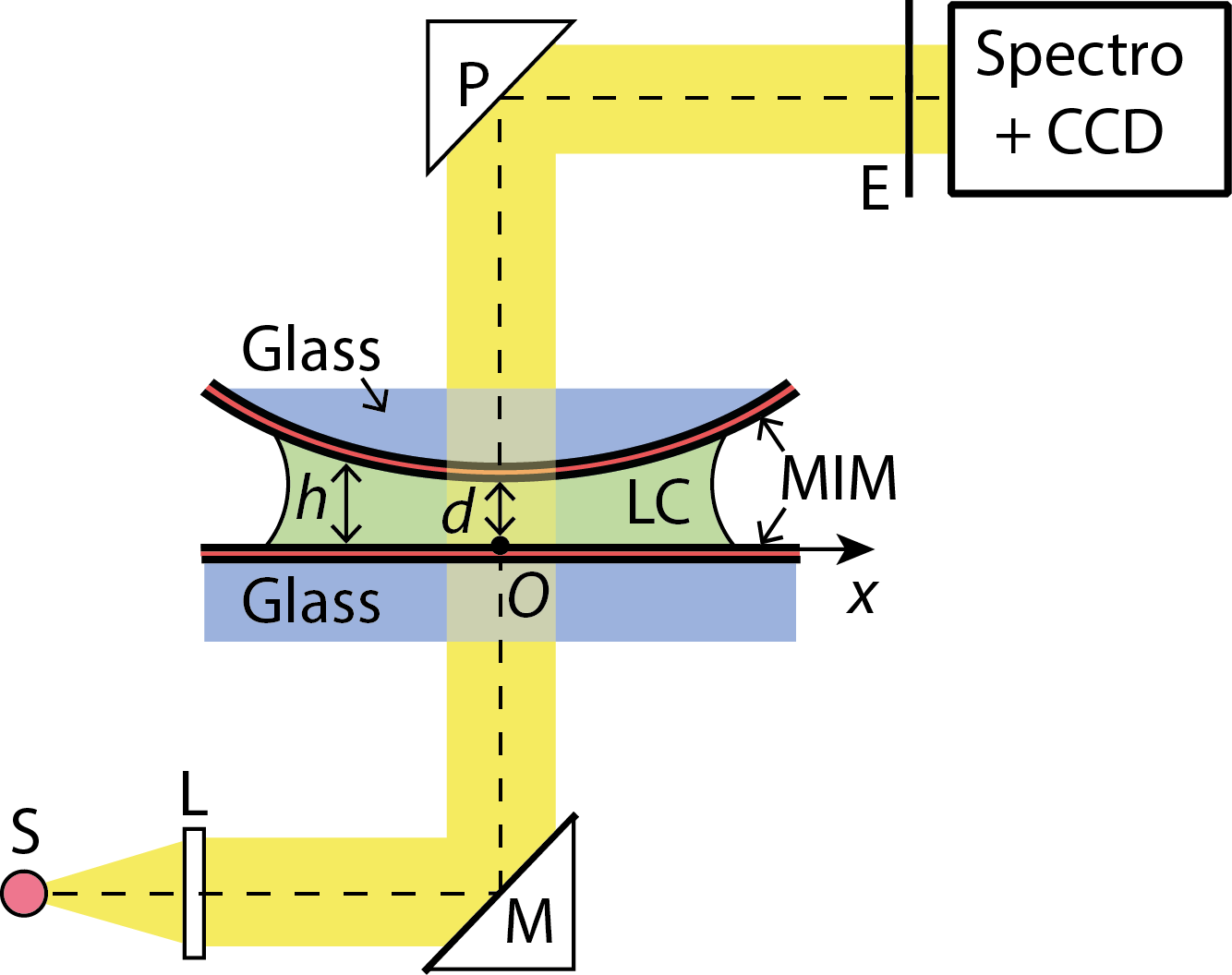
In this article, we present experimental and numerical evidence of optical coupling in ENZ multilayer metamaterials comprising a nanoscale high-birefringence LC film with tunable thickness achieved by means of a Surface Force Apparatus (SFA). Originally designed to measure surface forces across fluid films [41], the SFA has been recently introduced in photonics as a tool to control mode coupling in optical cavities [42, 24]. Specifically, we have investigated a system comprising a nanoscale LC film (T-layer) with variable thickness sandwiched between two identical metal-insulator-metal (MIM) cavities, thereby creating a symmetric three-cavity resonator denoted as MIMTMIM. The MIM cavities were fabricated by sputtering deposition on two cylindrical surfaces having a radius cm. The surfaces were mounted with crossed axes in the SFA ensuring a single contact point (i.e., point of closest surface approach, in Fig. 1b) where the surface distance was . Around this point, the distance varied approximately as in a sphere-plane geometry: . The three-cavity resonator was illuminated with white light under normal incidence. The SFA allowed controlling the LC thickness dynamically, accurately, and continuously from several tens of microns down to the direct mechanical contact between the MIM surfaces (Fig. 1a). Details about the SFA technique are provided in the Materials and method section and a scheme is shown as supporting information (Fig. S1).
II Mode coupling in a multi-cavity resonator
Let us begin the theoretical considerations with the analysis of multi-beam interference under normal incidence in a single (Fabry-Perot) MIM cavity constituted by an isotropic material (I-layer). A plane wave resonates with a cavity if the following condition of constructive interference occurs [43, 44]:
| (1) |
where is the refractive index of the cavity medium, is the metal-metal surface separation distance, is the resonance order, = is resonance wavevector with wavelength , and is the phase shift due to reflection at the dielectric-metal interface. Both and vary slowly with the wavelength and can be considered approximately constant across the 100 nm spectral range of an SFA experiment. The resonance condition Eq.1 can thus be rewritten as:
| (2) |
showing that the resonance wavelength increases linearly as the surface distance or the refractive index increases, whereas it decreases when the order number increases. The transmittance of a MIM cavity under normal incidence can be accurately calculated as a function of wavelength and the cavity thickness using the transfer matrix multiplication (TMM) method (green lines in Fig. 1b). For the MIM cavities considered in our experiments, only one resonance wavelength appeared in the SFA spectral range (vertical dashed black line in Fig. 1b). The TMM calculation showed that corresponded to the first resonant mode obtained for the MIM cavity thickness of = (horizontal dashed black line in Fig. 1b).
In a three-cavity MIMTMIM resonator, a cavity mode can overlap and interfere with the resonances of neighboring cavities across the metal (M) layers. Consequently, the coupling of resonances and the optical interaction among the cavities that give rise to hybrid resonance modes [42]. In the MIMTMIM resonator, hybridization is strongest between the outer MIM cavities and the central MTM cavity when the resonance wavelength of the former crosses the resonance wavelength of the latter. If the central liquid crystal cavity, T-layer indicated as (), is optically isotropic, hybridization creates a threefold splitting of the resonance, i.e., a triplet of wavelengths , and with increasing photon energy [42]. On the other hand, when the T-layer is an optically anisotropic LC film, these wavelengths depend on light polarization (purple and cyan curves in Fig. 1b). In contrast with Eq. 1, the resonance wavelengths and do not vary linearly with the thickness in proximity of the crossing point between and . However, as the wavelength departs from , hybridization weakens and and converge towards thus acquiring an almost linear dependence on . These preliminary considerations highlight the potential of birefringent materials for tuning the resonances of metal-dielectric metametarials.
III Experimental results
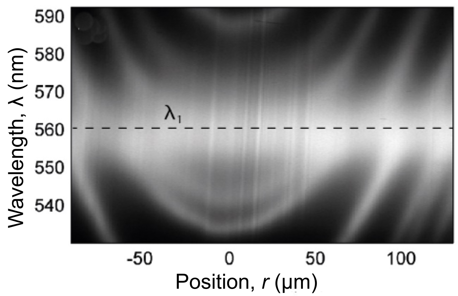
In the realized system, the thickness of silver (Ag, M-layers) and zinc oxide (ZnO, I-layers) is and , respectively. The LC material considered for the T-layer is a high-birefringence nematic liquid crystal mixture named LC1825, synthesized by the Military University of Warsaw [45] with a birefringence of , where and are the extraordinary and ordinary refractive indices at room temperature, respectively. The photoalignment compound JK158 [46] was spin-coated on the Ag surfaces facing the LC to induce planar orientation along the cylinder axis on one surface and perpendicular to the axis on the other surface. Crossing the axes in the SFA ensured a planar alignment uniform across the LC thickness. Therefore, polarized parallel or perpendicular to the LC orientation travelled in the LC film as purely extraordinary or ordinary waves, respectively. Further details on the fabrication and materials used in our experiments are provided in the Materials and methods section. During the experiment, a collimated white-light beam coming from a halogen lamp illuminated the MIMTMIM resonator under normal incidence and the transmitted intensity was analyzed using an imaging spectrograph coupled to a high-resolution CCD camera. In the spectrogram of Fig. 2, the transmitted intensity was measured as a 2D function of the wavelength and lateral distance for the contact point ( in FIg. 1). A resonance produces a local maximum in the intensity function . Because around the contact point, resonance wavelengths that depend linearly on vary quadratically with and create curved fringes in the SFA spectrograms with a parabolic tip corresponding to the contact point. In the spectrogram of Fig. 2b, the intensity was measured at the contact position () while increasing the surface distance at a constant speed of a few nm/s using a motorized actuator (Fig. 1). In this case, the intensity was resolved as a 2D-function of and time. Because ,where is the initial thickness, each vertical line in the spectrogram corresponds to a specific time and surface distance . The advantage of this approach is that the SFA can vary dynamically and continuously over a wide range of surface distances, from several m to direct surface contact ( nm for molecularly smooth surfaces), with an accuracy better than 1 nm and execution time of the order of minutes. To vary , the surfaces were approached to or separated from each other at a constant speed. By recording , the SFA allowed studying the resonance dispersion as a function of the cavity thickness in a single sweep of thickness, instead of fabricating multiple cavities with different thicknesses. In the spectrograms of Fig. 2a,b, the first-order resonance of the fixed-thickness MIM cavities produces a specific resonance wavelength that does not depend on the thickness ( or ) of the MTM cavity, i.e., the LC film. On the other hand, the other fringes in the spectrogram are due to resonances of the MTM cavity and, therefore, depend both on the film thickness and polarization of the incident light. For a fixed surface distance ( or ) and far from , these fringes show an approximately parabolic shape (Fig. 2a) reflecting the surface curvature, as expected. Due to the LC birefringence, these fringes form two distinct sets that can be separately extinguished using a linear polarizer parallel or perpendicular to the planar anchoring direction, as shown in Fig. 2a (see also an example of unpolarized spectrogram in Fig. S2 of SI). This finding demonstrates that the resonance modes of the MTM cavity are linearly polarized along the ordinary and extraordinary axis of the uniformly aligned LC. The extraordinary modes appear slightly brighter than the ordinary ones (Fig. S2 in SI), because light was directed into the spectrograph using a right-angle mirror with polarization-dependent reflectivity (Fig. S1 in SI).
This allows to identify the fringe polarization even though we cannot use a polarizer to dynamically resolve the polarization while varying . Figure 2b shows that extraordinary fringes enter and exit the spectral range of the SFA (at a wavelengths distant from ) more rapidly than ordinary fringes. In the entrance and exit regions, resonances approximately follow Eq. 1. Therefore, if the mode with order resonates at a given wavelength , then the mode with order resonates at the same wavelength after displacing the surfaces by a distance . As a result of the inequality , extraordinary fringes with index cross the wavelength more often than ordinary fringes as the distance is increased. If the surfaces are separated at a constant speed , the fringe with order exits the spectral range after a time compared to the fringe with order . Figure 2b shows ordinary fringes exiting the spectral range at wavelength at periodic time intervals s, whereas the period is s for extraordinary fringes. The ratio of these two periods, , is in good agreement with the value predicted by Eq. 1 using the nominal refractive indices (at room temperature) and of the LC.
Figures 3a and 3b show intensity spectrograms obtained for the ordinary and extraordinary polarization, respectively, by using a polarizer in transmission. Resonance wavelengths are highlighted by black dashed lines and are referred to as , and . As the thickness of the LC film increases, approaches while departs from . Eventually, and become equally spaced from by a distance . This behaviour agrees with the numerical prediction and demonstrate the possibility of dynamically tuning the modes at different wavelengths ranging from to by acting on LC thickness or incoming light polarization.
IV Tuning mode coupling via LC confinement and reorientation
In order to understand why mode coupling produces a wavelength triplet, we calculated the transmitted intensity as a function of wavelength and LC film thickness using the TMM method (Fig. 4a), and selected three different values of to compute, by a finite element method (COMSOL), the electric field map along the direction perpendicular to the MIMTMIM resonator as a function of and position [2] (Fig. 4(b-e)).
For nm and ordinary polarization (Fig. 4b), the high-energy mode has wavelength and is farther away from than the low-energy mode with wavelength . This unequal wavelength spacing is reflected in mode hybridization. Namely, the high-energy mode is mainly located in the central MTM cavity while the low-energy mode is more delocalized among the central and outer (MIM) cavities. When the LC film thickness is increased to nm (Fig. 4c), the high-energy wavelength (Fig. 4c) and low-energy wavelength are almost equally spaced from and show a comparable degree of delocalization. When the LC film thickness is further increased to nm (Fig. 4d), the situation shown in Fig. 4b is reversed and the high-energy mode at is closer to and more delocalized than the low-energy mode at . Mode hybridization in MIMTMIM resonator can be understood based on its mirror symmetry under reflection on the middle plane of the central T-cavity. Symmetry requires that resonances be either even (+) or odd (-) under reflection (Fig 4(b-e)). Using first-order perturbation theory or variational method [47, 42], these modes can be approximated as symmetry-adapted linear combinations of single-cavity modes. In particular, the field of first-order mode in the central cavity is even and, therefore, hybridizes with the field of the even combination of outer-cavity modes. Against, the odd combination cannot hybridize with an even mode such as . While the modes and overlap and interfere with each other, particularly within the metal layers of the central MTM cavity, direct overlap and interference between the outer cavities is negligible and, as a result, the wavelength of the mode is very close to the wavelength of an isolated MIM cavity. Indeed, the difference between and was too small to be detected in our experiments.
Hybridization between same-parity modes produces the wavelengths and observed both in the SFA experiments and in our calculation [42]. For first-order modes, these wavelengths correspond to the modes and , respectively, where the positive linear coefficients and depend on the thickness of the central MTM cavity. The wavelengths and are due to the anti-crossing interaction between the even mode and occurring as varies (Fig 4(b-d)). Namely, the -mode repels the -mode as it moves towards lower energies, while the mode is unaffected. The avoided-crossing point is reached when the wavelength of the -mode (Eq. 1) overlaps with the first-order wavelength of the outer MIM cavities. In other words, the difference or ”detuning” between the photon energies of the two modes becomes zero. At this point, the modes and become uniformly delocalized across the resonator, with equal intensity maxima in each cavity (,, Fig 4c). At the avoided-crossing point, the wavelengths and are found at an equal distance from the wavelength of the mode.
A decisive advantage of using an anisotropic LC film is that the detuning can be actively controlled not only by varying the MTM cavity thickness, but also by selecting the refractive index of the LC. This fact is highlighted in Eq. 1 showing that the resonance wavelength depends on the product and, therefore, the thickness and index play equivalent roles. For example, the transmittance variation obtained by increasing the film thickness from 100 nm (Fig. 4b) to 134 nm (Fig. 4c) can also be obtained by switching the refractive index from ordinary to extraordinary (Fig. 4d) while keeping the film thickness fixed to 100 nm. The switching can be obtained by changing the polarization from ordinary to extraordinary, or acting on the LC orientation (e.g., by applying a voltage to the silver surfaces of the MTM cavity) so as to vary the refractive index seen by extraordinary waves.
As a further demonstration of mode hybridization, the electric field was calculated using finite element method for the three LC thicknesses under normal incidence in Fig. S3 of SI. In Fig. S4 of SI the transmittance plots, electric field confinement into the LC cavity (), and electric field distributions along the propagation direction are also shown.
In Fig. 5a, the wavelength splitting related to the difference , and is shown as a function of the LC thickness. The top and bottom panels show the resonance wavelengths retrieved via a multiple Gaussian fit on the transmittance curves, for the anti-crossing behaviour represented by approaching , approaching , and approaching , for the ordinary and extraordinary LC refractive index, respectively. The minimum value of corresponds to the avoided-crossing point and maximum coupling between same-parity modes. The same behaviour is observed in experiments (Fig. 5b). The slight difference related to the amplitude () reported in both plots, numerical and experimental ones, for extraordinary polarization is a consequence of the non negligible effect of changing the surrounding medium around the two MIM resonators. In SI, we also simulated the angular dependence by varying the incident angle from to in steps of for both ordinary and extraordinary polarization (Fig. S5. The results show that the three-cavity resonator is not significantly perturbed by the variation of the incident angle, especially for the extraordinary polarization .
V Conclusions
In conclusion, we presented a detailed study on how to design and actively tune strongly confined hybrid modes in one-dimensional layered structures working in visible wavelengths. The active control is enabled by a high-birefringence LC in combination with an SFA that can vary the cavity thickness rapidly, continuously, and accurately from several m down to direct contact between its metal mirror surfaces. Importantly, we studied numerically and experimentally how the system performs in terms of weak and strong light coupling conditions when an LC film is confined between two MIM cavities. This result has significant practical implications for the development of innovative devices as it enables the possibility to excite multiple resonant modes across the LC cavity. This is of fundamental importance for developing active and reconfigurable devices that can find applications as a platform for optical beam steering devices.. Thanks to the tunability of these photonic modes, the proposed system can be of extremely high importance for bio-sensing where it is necessary to involve high energy modes (short wavelengths, from to ) excitable in free-space. Although the cavity resonances were obtained under normal incidence, it is expected that plasmonic modes can also be excited in a multi-cavity metamaterials under oblique incidence, notably without using any coupler (i.e, a grating) to generate evanescent waves. To this end, the SFA could be used to study the generation, coupling, and transmission of plasmonic modes in multi-cavity metamaterials as a function of the thickness and refractive index of LC loaded cavity.
Materials and Method
Samples Fabrication:
The MIM cavities were fabricated by DC/RF sputtering (model Kenosistec KC300C), and they were constituted of Ag and transparent Zinc-oxide (ZnO), respectively with target thickness of 30 and 95 nm, on cylindrical glass lenses. The lenses had diameter of R = 2 cm , the thickness of 4 mm, 60/ 40 scratch/dig surface quality, centration wedge angle 5 arcmin, and irregularity (interferometer fringes) /2 at a wavelength of 630 nm. Ag was chosen for its large extinction coefficient 1 , ensuring a high reflectivity and an approximately real negative permittivity in the metal layers while ZnO was chosen for its transparency ( 1 ).
For the deposition, the following parameters were used: vacuum , DC power for for Ag layer while ZnO were deposited using the RF cathode at a power of and time of .
In order to align the LC layer, a solution photo-active poly(amide imide), denominated JK158 in N-methylpyrrolidone (1 wt.) was spin-coated on top of the exposed Ag layers. The poly(amide imide) was described in [48]. JK158 contains randomly aligned azo-dye molecules that reorient perpendicularly to the polarization direction of UV light to minimise the absorption cross-section. The LCs in contact with the aligned JK158 molecules acquire the same alignment.
SFA Experiments:
A surface forces apparatus (SFA) Mark III by Surforce LLC, USA was used in the experiments [42, 49]. One of the MIM-coated cylindrical lenses was fixed on a rigid support, whereas the other one was attached to the free end of a double cantilever spring. The surfaces of the lenses were sufficiently far apart from each other to avoid any mechanical interaction and moved freely in contact with a 50 L droplet of LC. The droplet was infiltrated between the MIM-coated lenses by capillarity.
Transmission spectra were obtained by illuminating the MIMTMIM cavity (consisting of the metal- insulator- metal layers on the lens surfaces and the LC solution) under normal incidence with white light from a halogen lamp. The transmitted light was collected through the entrance slit of an imaging spectrograph (PI Acton Spectra Pro 2300i) aligned with one of the cylindrical lenses, and recorded with a high-sensitivity CCD camera (Andor Newton DU940P-FI). Only a small region of the surface surrounding the contact position was probed, such that , equivalent to a sphere-plane geometry [50]. A CCD camera image recorded the transmitted intensity I as a function of the wavelength and position r. Multi-beam interference created resonance peaks in a spectrogram, i.e., local maxima of the 2d intensity function , corresponding to constructive interference. Spectrograms were obtained by combining multiple CCD images taken in different but overlapping spectral intervals. Each image was recorded within in less than one second, whereas a spectrogram was completed in less than 20 s.
Numerical simulations:
The transfer matrix method (TMM) analysis were performed using a script implemented in commercial software Matlab. It uses as input the refractive indices data, retrieved by ellipsometry for the used materials, the layer thicknesses and it allows calculating the spectrum varying the T cavity thickness.
Finete Element Method (FEM) simulation were performed using COMSOL Multiphysics with the same scheme reported in [2]. In order to analyse the electric filed , where has been calculated as , here P is the input power (), represents the area illuminated by the light beam and Z0 is the impedance, in the MIMTMIM system a 1D cutting line have been used to collect the normalized electric filed as function of the structure size and wavelengths. The cutting line has been chose to cover the entire length of the MIMTMIM system plus extra 20 nm in the glass before and after the structure.
Acknowledgements.
This research is performed in the framework of the bilateral (Italy-Poland) project: ”Active metamaterials based on new generation liquid crystals (LCMETA)” funded by the Italian Ministry of Foreign Affairs and International Cooperation and the Polish National Agency for Academic Exchange NAWA. G.E.L and F.R. thank the FASPEC (Fiber-Based Planar Antennas for Biosensing and Diagnostics) - supported by Tuscany region in the Horizon 2020 framework - and the project ”Complex Photonic Systems (DFM.AD005. 317). G.E.L. also thanks the research project ”FSE-REACT EU” financed by National Social Fund - National Operative Research Program and Innovation 2014-2020 (DM 1062/2021). A.F and R.C thank the project “DEMETRA – Sviluppo di tecnologie di materiali e di tracciabilità per la sicurezza e la qualità dei cibi” PON ARS01 00401. R.K. and J.P. acknowledge the financial support from the MUT University Grant UGB 22 804 from funds for year 2023.Authors contribution
G.E.L. and A.F. equally contributed to this work and wrote the article. G.E.L and R.C. conceived the main idea in the framework of the research project ”LCMETA”. G.E.L and A.F. performed numerical simulations and samples fabrication. B.Z. performed the SFA measurements and provided theoretical explanations. E.S-B. synthesized and delivered LC photoaligning materials and supported the work with fundamental technical advice. R.K. tested photo-aligning materials. J.P., R.K., C.P.U., F.R., and R.C. provided fundamental support thanks to their expertise in liquid crystals. F.R. provided his expertise on light coupling behavior in complex media to explain the physics behind this work. All authors revised the paper and accepted its contents.
References
- Réveret et al. [2008] F. Réveret, P. Disseix, J. Leymarie, A. Vasson, F. Semond, M. Leroux, and J. Massies, Influence of the mirrors on the strong coupling regime in planar gan microcavities, Physical Review B 77, 195303 (2008).
- Lio et al. [2019] G. E. Lio, G. Palermo, R. Caputo, and A. De Luca, A comprehensive optical analysis of nanoscale structures: from thin films to asymmetric nanocavities, RSC Adv. 9, 21429 (2019).
- Cao et al. [2021] J. Cao, S. De Liberato, and A. V. Kavokin, Strong light–matter coupling in microcavities characterised by rabi-splittings comparable to the bragg stop-band widths, New Journal of Physics 23, 113015 (2021).
- Choudhury et al. [2016] S. M. Choudhury, A. Shaltout, V. M. Shalaev, A. V. Kildishev, and A. Boltasseva, Experimental realization of color hologram using pancharatnam-berry phase manipulating metasurface, in CLEO: QELS_Fundamental Science (Optical Society of America, 2016) pp. FF1D–8.
- Lio et al. [2020] G. E. Lio, A. Ferraro, M. Giocondo, R. Caputo, and A. De Luca, Color gamut behavior in epsilon near-zero nanocavities during propagation of gap surface plasmons, Advanced Optical Materials 8, 2000487 (2020).
- Guo et al. [2018] Z. Guo, H. Jiang, K. Zhu, Y. Sun, Y. Li, and H. Chen, Focusing and super-resolution with partial cloaking based on linear-crossing metamaterials, Physical Review Applied 10, 064048 (2018).
- Lio et al. [2021] G. E. Lio, A. Ferraro, T. Ritacco, D. M. Aceti, A. De Luca, M. Giocondo, and R. Caputo, Leveraging on enz metamaterials to achieve 2d and 3d hyper-resolution in two-photon direct laser writing, Advanced Materials 33, 2008644 (2021).
- Shaltout et al. [2016] A. M. Shaltout, N. Kinsey, J. Kim, R. Chandrasekar, J. C. Ndukaife, A. Boltasseva, and V. M. Shalaev, Development of optical metasurfaces: emerging concepts and new materials, Proceedings of the IEEE 104, 2270 (2016).
- Kowerdziej et al. [2022] R. Kowerdziej, A. Ferraro, D. C. Zografopoulos, and R. Caputo, Soft-matter-based hybrid and active metamaterials, Advanced Optical Materials 10, 2200750 (2022).
- Dyachenko et al. [2016] P. N. Dyachenko, S. Molesky, A. Y. Petrov, M. Störmer, T. Krekeler, S. Lang, M. Ritter, Z. Jacob, and M. Eich, Controlling thermal emission with refractory epsilon-near-zero metamaterials via topological transitions, Nature communications 7, 1 (2016).
- Ferraro et al. [2021] A. Ferraro, G. E. Lio, A. Hmina, G. Palermo, J. M. Djouda, T. Maurer, and R. Caputo, Tailoring of plasmonic functionalized metastructures to enhance local heating release, Nanophotonics (2021).
- Sreekanth et al. [2016] K. V. Sreekanth, Y. Alapan, M. ElKabbash, E. Ilker, M. Hinczewski, U. A. Gurkan, A. De Luca, and G. Strangi, Extreme sensitivity biosensing platform based on hyperbolic metamaterials, Nat. Mater. 15, 621 (2016).
- Sreekanth et al. [2013] K. V. Sreekanth, S. Zeng, K.-T. Yong, and T. Yu, Sensitivity enhanced biosensor using graphene-based one-dimensional photonic crystal, Sens. Actuators, B 182, 424 (2013).
- Lio et al. [2023] G. E. Lio, A. Ferraro, R. Kowerdziej, A. O. Govorov, Z. Wang, and R. Caputo, Engineering fano-resonant hybrid metastructures with ultra-high sensing performances, Advanced Optical Materials , 2203123 (2023).
- Ferraro et al. [2022] A. Ferraro, G. E. Lio, M. D. L. Bruno, S. Nocentini, M. P. De Santo, D. S. Wiersma, F. Riboli, R. Caputo, and R. C. Barberi, Hybrid camouflaged anticounterfeiting token in a paper substrate, Advanced Materials Technologies , 2201010 (2022).
- Vassant et al. [2012] S. Vassant, J.-P. Hugonin, F. Marquier, and J.-J. Greffet, Berreman mode and epsilon near zero mode, Optics express 20, 23971 (2012).
- Reshef et al. [2019] O. Reshef, I. De Leon, M. Z. Alam, and R. W. Boyd, Nonlinear optical effects in epsilon-near-zero media, Nature Reviews Materials 4, 535 (2019).
- Wu et al. [2021] J. Wu, Z. T. Xie, Y. Sha, H. Fu, and Q. Li, Epsilon-near-zero photonics: Infinite potentials, Photonics Research 9, 1616 (2021).
- Jin and Ziolkowski [2010] P. Jin and R. Ziolkowski, Multiband extensions of the electrically small, near-field resonant parasitic z antenna, IET microwaves, antennas & propagation 4, 1016 (2010).
- Li et al. [2015] Z. Li, S. Butun, and K. Aydin, Large-area, lithography-free super absorbers and color filters at visible frequencies using ultrathin metallic films, Acs Photonics 2, 183 (2015).
- Heydari and Sabaeian [2017] M. Heydari and M. Sabaeian, Plasmonic nanogratings on mim and soi thin-film solar cells: comparison and optimization of optical and electric enhancements, Applied optics 56, 1917 (2017).
- Imamog et al. [1999] A. Imamog, D. D. Awschalom, G. Burkard, D. P. DiVincenzo, D. Loss, M. Sherwin, A. Small, et al., Quantum information processing using quantum dot spins and cavity qed, Physical review letters 83, 4204 (1999).
- Greentree et al. [2006] A. D. Greentree, C. Tahan, J. H. Cole, and L. C. Hollenberg, Quantum phase transitions of light, Nature Physics 2, 856 (2006).
- Patra et al. [2023] A. Patra, V. Caligiuri, B. Zappone, R. Krahne, and A. De Luca, In-plane and out-of-plane investigation of resonant tunneling polaritons in metal–dielectric–metal cavities, Nano Letters 23, 1489 (2023).
- Vahala [2003] K. J. Vahala, Optical microcavities, nature 424, 839 (2003).
- Liang et al. [2013] F. Liang, N. Clarke, P. Patel, M. Loncar, and Q. Quan, Scalable photonic crystal chips for high sensitivity protein detection, Optics express 21, 32306 (2013).
- Frisk Kockum et al. [2019] A. Frisk Kockum, A. Miranowicz, S. De Liberato, S. Savasta, and F. Nori, Ultrastrong coupling between light and matter, Nature Reviews Physics 1, 19 (2019).
- Herzog et al. [2020] T. Herzog, S. Böhrkircher, S. Both, M. Fischer, R. Sittig, M. Jetter, S. Portalupi, T. Weiss, and P. Michler, Realization of a tunable fiber-based double cavity system, Physical Review B 102, 235306 (2020).
- Smith et al. [2020] K. C. Smith, Y. Chen, A. Majumdar, and D. J. Masiello, Active tuning of hybridized modes in a heterogeneous photonic molecule, Physical Review Applied 13, 044041 (2020).
- Cui et al. [2019] T. Cui, B. Bai, and H.-B. Sun, Tunable metasurfaces based on active materials, Advanced Functional Materials 29, 1806692 (2019).
- De Bellis et al. [2023] I. De Bellis, D. Martella, C. Parmeggiani, D. S. Wiersma, and S. Nocentini, Temperature tunable 4d polymeric photonic crystals, Advanced Functional Materials , 2213162 (2023).
- Zubritskaya et al. [2023] I. Zubritskaya, R. Cichelero, I. Faniayeu, D. Martella, S. Nocentini, P. Rudquist, D. S. Wiersma, and M. L. Brongersma, Dynamically tunable optical cavities with embedded nematic liquid crystalline networks, Advanced Materials , 2209152 (2023).
- Sharma and Ellenbogen [2020] M. Sharma and T. Ellenbogen, An all-optically controlled liquid-crystal plasmonic metasurface platform, Laser & Photonics Reviews 14, 2000253 (2020).
- Lio and Ferraro [2021] G. E. Lio and A. Ferraro, Lidar and beam steering tailored by neuromorphic metasurfaces dipped in a tunable surrounding medium, Photonics 8, 10.3390/photonics8030065 (2021).
- Wang et al. [2022] J. Wang, K. Li, H. He, W. Cai, J. Liu, Z. Yin, Q. Mu, V. K. Hisao, D. Gérard, D. Luo, et al., Metasurface-enabled high-resolution liquid-crystal alignment for display and modulator applications, Laser & Photonics Reviews , 2100396 (2022).
- Palermo et al. [2022] G. Palermo, A. Lininger, A. Guglielmelli, L. Ricciardi, G. Nicoletta, A. De Luca, J.-S. Park, S. W. D. Lim, M. L. Meretska, F. Capasso, et al., All-optical tunability of metalenses permeated with liquid crystals, ACS nano 16, 16539 (2022).
- Kowerdziej et al. [2013] R. Kowerdziej, J. Krupka, E. Nowinowski-Kruszelnicki, M. Olifierczuk, and J. Parka, Microwave complex permittivity of voltage-tunable nematic liquid crystals measured in high resistivity silicon transducers, Applied Physics Letters 102, 102904 (2013).
- Zografopoulos et al. [2019] D. C. Zografopoulos, A. Ferraro, and R. Beccherelli, Liquid-crystal high-frequency microwave technology: Materials and characterization, Advanced Materials Technologies 4, 1800447 (2019).
- Kowerdziej et al. [2015] R. Kowerdziej, T. Stańczyk, and J. Parka, Electromagnetic simulations of tunable terahertz metamaterial infiltrated with highly birefringent nematic liquid crystal, Liquid Crystals 42, 430 (2015).
- Isić et al. [2019] G. Isić, G. Sinatkas, D. C. Zografopoulos, B. Vasić, A. Ferraro, R. Beccherelli, E. E. Kriezis, and M. Belić, Electrically tunable metal–semiconductor–metal terahertz metasurface modulators, IEEE Journal of Selected Topics in Quantum Electronics 25, 1 (2019).
- Israelachvili and McGuiggan [1990a] J. N. Israelachvili and P. M. McGuiggan, Adhesion and short-range forces between surfaces. part i: New apparatus for surface force measurements, Journal of Materials Research 5, 2223–2231 (1990a).
- Zappone et al. [2021] B. Zappone, V. Caligiuri, A. Patra, R. Krahne, and A. De Luca, Understanding and controlling mode hybridization in multicavity optical resonators using quantum theory and the surface forces apparatus, ACS Photonics 10.1021/acsphotonics.1c01055 (2021).
- Fowles [1989] G. Fowles, Modern optics. new york: Holt (1989).
- Born and Wolf [2013] M. Born and E. Wolf, Principles of optics: electromagnetic theory of propagation, interference and diffraction of light (Elsevier, 2013).
- Dkabrowski et al. [2013] R. Dkabrowski, P. Kula, and J. Herman, High birefringence liquid crystals, Crystals 3, 443 (2013).
- Wegłowski et al. [2015] R. Wegłowski, W. Piecek, A. Kozanecka-Szmigiel, J. Konieczkowska, and E. Schab-Balcerzak, Poly (esterimide) bearing azobenzene units as photoaligning layer for liquid crystals, Optical Materials 49, 224 (2015).
- Caligiuri et al. [2019] V. Caligiuri, M. Palei, G. Biffi, and R. Krahne, Hybridization of epsilon-near-zero modes via resonant tunneling in layered metal-insulator double nanocavities, Nanophotonics 8, 1505 (2019).
- Konieczkowska et al. [2015] J. Konieczkowska, E. Schab-Balcerzak, M. Siwy, K. Switkowski, and A. Kozanecka-Szmigiel, Large and highly stable photoinduced birefringence in poly (amideimide) s with two azochromophores per structural unit, Optical Materials 39, 199 (2015).
- Israelachvili and McGuiggan [1990b] J. N. Israelachvili and P. M. McGuiggan, Adhesion and short-range forces between surfaces. part i: New apparatus for surface force measurements, Journal of Materials Research 5, 2223 (1990b).
- Israelachvili [2011] J. N. Israelachvili, Intermolecular and surface forces (Academic press, 2011).
Supplementary Information
Unlocking optical coupling tunability in epsilon-near-zero metamaterials through liquid crystal nanocavities
Surface Force Apparatus (SFA)
Figure S1 shows a schematic of the SFA setup.
Experimental measurements
Figure S2 shows the transmitted intensity of a MIMTMIM resonator as a function of the wavelength and lateral distance from the surface contact position () without polarizers.
Numerical simulations
Here are reported the further numerical simulations performed to confirm the trends shown in the main paper.