ToothSegNet: Image Degradation meets Tooth Segmentation in CBCT Images
Abstract
In computer-assisted orthodontics, three-dimensional tooth models are required for many medical treatments. Tooth segmentation from cone-beam computed tomography (CBCT) images is a crucial step in constructing the models. However, CBCT image quality problems such as metal artifacts and blurring caused by shooting equipment and patients’ dental conditions make the segmentation difficult. In this paper, we propose ToothSegNet, a new framework which acquaints the segmentation model with generated degraded images during training. ToothSegNet merges the information of high and low quality images from the designed degradation simulation module using channel-wise cross fusion to reduce the semantic gap between encoder and decoder, and also refines the shape of tooth prediction through a structural constraint loss. Experimental results suggest that ToothSegNet produces more precise segmentation and outperforms the state-of-the-art medical image segmentation methods.
Index Terms— Tooth Segmentation, CBCT, Orthodontics, Tooth Models, Image Degradation
1 Introduction
Stomatologists and dentists use tooth models to carry out diagnosis, orthodontic treatment planning and dental restoration [1]. Constructing a tooth model first requires tooth segmentation from CBCT scans [2]. Existing computational methods then generate the final tooth models according to the segmentation. Traditionally, specialists have to manually label each tooth from CBCT images slice by slice, which is a huge workload and extremely time-consuming. It is therefore practically demanded to design accurate and fully automatic end-to-end methods to attain tooth segmentation from CBCT images [3].
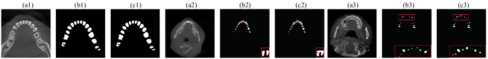
In recent years, deep learning has been increasingly applied to image segmentation tasks in various medical areas including dentistry [2]. Some prior works [4], [5] formulated CBCT tooth segmentation task as 3D instance segmentation which usually demands labeling tooth pixels and instances on 3D voxels across the entire CBCT scan. To explore a more efficient way, we recognize the task as semantic segmentation over 2D CBCT images to alleviate the data annotation labour. Directly applying current segmentation methods to the 2D case [6], however, leads to unsatisfied results because of the existence of low-quality images. Fig.1 illustrates two most commonly seen defects in dental CBCT images [7]: (a) consecutively displays a high quality CBCT image, an image with metal artifacts and an image with blurring; (b) and (c) give respective ground truth and segmentation results of U-Net [6]; the red boxes are magnification areas for metal artifacts and blurring. The second and third triplets indicate that such image defects can lead to abysmal tooth segmentation. Addressing these problems should greatly improve 2D CBCT tooth segmentation, promising an efficient and effective tooth modeling for the dentistry community.
In this study, we propose a metal artifacts and blurring robust and teeth structural constrained tooth segmentation method named ToothSegNet. The philosophy is to acquaint the deep model with defective cases when learning each CBCT image sample. Experiments show that our method not only outperforms the state-of-the-art segmentation methods on high-quality images but also has a strong robustness to images with metal artifacts and blurring, suggesting the applicability of our framework in real-world clinical scenarios. The main contributions are summarized below:
-
•
We propose a medical image degradation simulation strategy, combined with a multi quality fusion module, to attain higher robustness to problematic images.
-
•
We design a channel-wise cross fusion module (CCF) to reduce the semantic gap between the encoder and decoder, which eliminates the ambiguity features existed in vanilla U-Net caused by skip-connection.
-
•
We design a structural constraint loss in order to restrict the structure of tooth prediction.
-
•
We explore an annotation approach which is much lower-cost than that implemented in current CBCT tooth segmentation methods.
2 Method
2.1 Overview
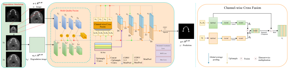
Suppose we have a dataset , where and denote the -th CBCT image and corresponding pixel-level segmentation labels respectively, is the number of images in the dataset. For each pixel, we use to denote the background and tooth respectively. In our task, we aim to generate accurate pixel-level predictions for each input image. As is illustrated in Fig. 2, ToothSegNet is composed of the degradation simulation module, multi-quality fusion module, CCF, vanila U-Net decoder, SE-Net [8] and the structural constraint loss. The vanila U-Net decoder follow the conventional CNN-based architecture [6].
2.2 Degradation simulation module
In computer vision tasks, people often construct data sets through image degradation to mimic complex real-world scenarios [9], [10]. Referred to that, ToothSegNet randomly degrades the input image during training. For blurring and double blurring simulation, the input image is down-sampled once (1x) and twice (2x) respectively and then up-sampled to generate the degraded image , as is shown in Fig. 2. In the downsampling, a Gaussian pyramid blurring is performed to downscale the image. In the upsampling, a bilinear interpolation is performed to convert images to the original size. For artifact simulation, since we observe that the teeth with metal have higher image contrast compared with others, we create contrast enhanced images by image square.
The degradation simulation procedure is defined to follow the operation probability distribution:
| (1) |
where and denote an input CBCT image and its degradation simulation, to represent the blurring degradation, double blurring degradation, no operation for source images and artifact degradation respectively.
2.3 Network architecture
2.3.1 Multi-quality fusion module
After the degraded images are obtained, the source and degraded images are sent to a designed multi-quality fusion module similar to the two-branch improved U-Net encoder. As shown in Fig. 2, the blue branch is the vanilla U-Net encoder which encodes the feature of source images, the green branch is the U-Net encoder with 1x1 convolution which encodes the feature of degraded images. The fused feature is defined as follows:
| (2) |
is the fused feature.
2.3.2 Channel-wise cross fusion
Shallow layer features with less semantic information may damage performance via a skip connection in conventional U-Net [11]. To solve this issue, we design the CCF module, similar to channel attention [8], [11], to increase the semantic gap between teeth and the background. Fig. 2 shows the framework of CCF. The encoded CCF feature is defined as:
| (3) |
The feature fusion of CCF in Fig.2 is defined as:
| (4) |
Also, the SE-Net module is added to exploit the correlation of feature channels, enhancing the feature representation:
| (5) |
where denotes the SE-Net. are the fused features of inconsistent semantics between the CCF and SE-Net.
2.4 Structural constraint loss
With noise in images, the inference often lose the tooth structure. Thus, we design the structural constraint loss based on the structural similarity index measure (SSIM) [12]:
| (6) |
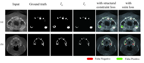
where is the ground truth zero-one vector, is the prediction of ToothSegNet, is the element-wise multiplication between and which, as shown in Fig. 3, retains the correctly predicted area in and sets the wrong predicted area to 0. ensures that the prediction approaches structurally, effectively constraining the results.
The total loss function is the sum of three losses:
| (7) |
Besides , is based on the Dice metrics [13] and is the binary cross-entropy (BCE) loss [13].
2.5 Training details
We set the batch size to 4 and the epoch to 300. The input resolution and patch size are set as 512 x 512 and 16 respectively. For optimizer, we use Adam with the initial learning rate to be 0.01. We perform a number of data augmentations including horizontal flipping, vertical flipping and random rotating.
3 Experiment
3.1 Dataset
We construct a large-scale CBCT dataset consisting of 503 patient samples from hospitals and clinics across 25 provinces in China during 2018-2021. The 503 patients are at the age of 19.53±7.57 years old, with 32.5% male and 67.5% female. Each patient has 400 slices, from which we select 15-25 slices to annotate to make sure labeled images contain different anatomical information. Selected images are annotated with software Labelme, under the supervision of senior radiologists with more than 10 year experience. Accordingly, the dataset has 9651 CBCT images in total from which 8612 images of 453 patients are used to train the model and 1039 images of 50 patients are used to test the model.
| IoU | Dice | Recall | Precision | |
| U-Net[6] | 81.12±5.18 | 88.95±3.54 | 94.63±4.12 | 84.82±5.35 |
| U-Net++[14] | 80.70±5.53 | 88.61±3.78 | 93.17±4.40 | 85.46±5.40 |
| FCN [15] | 78.82±6.98 | 87.32±4.95 | 90.56±5.73 | 85.42±5.84 |
| DeepLabv3[16] | 78.79±6.90 | 87.29±4.88 | 90.47±5.67 | 85.49±5.88 |
| MeDT[17] | 73.87±13.8 | 82.35±12.6 | 76.98±14.3 | 94.42±4.91 |
| UCTransNet[11] | 76.86±7.09 | 85.37±4.81 | 97.27±2.90 | 78.70±7.83 |
| ToothSegNet | 82.24±6.38 | 89.74±4.07 | 95.71±3.83 | 85.51±7.66 |
3.2 Main results
To demonstrate the overall segmentation performance of the proposed ToothSegNet, we compare it with six methods for a comprehensive evaluation, covering four U-Net based methods: U-Net [6], UNet++ [14], FCN [15], Deeplabv3 [16] and two state-of-the-art transformer-based segmentation methods: MedT [17], and UCTransNet [11]. To make a fair comparison, the implementations of MedT, UCTransNet, UNet, and UNet++ are based on their original source codes, and the implementations of FCN, and Deeplabv3 are based on the codes from MMsegmentation [18] where their originally published settings are used in the experiment. The backbone of DeepLabv3 and FCN is ResNet-50, and the training hyper parameters are in MMSegmentation [18] by default, the training procedure lasts for 160K iterations. Experimental results are reported in Table 1 where the best results are boldfaced, and the second results are underlined.
Each entry of Table 1 exhibits the average over 50 patient samples. The results indicate that ToothSegNet attains noticeable improvements over prior arts. In clinics, the segmentation results of tooth CBCT images need to be reconstructed into 3D mesh images, which turns out to require a balance between false positives and false negatives. Therefore, CBCT segmentation favors higher Dice and IoU. ToothSegNet achieves 89.74% Dice and 82.24% IoU with testing, which surpasses UCTransNet by 4.37% Dice, and 5.38% IoU.
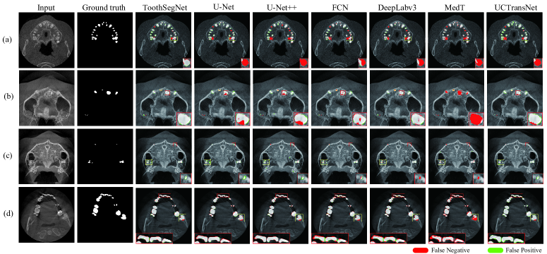
We visualize the segmentation results of all models in Fig. 4 where The red boxes contains FN pixels(red) and FP pixels(green). Fig. 4 (a) shows the results of a high-quality CBCT image on which ToothSegNet outperforms other methods. (b), (c) show the results of CBCT images with blurring, illustrating that our method generates segmentation results more similar to the ground truth than others. (d) shows the results of a CBCT image with metal artifacts, demonstrating that ToothSegNet have the best performance on tooth boundaries.
3.3 Reconstruction
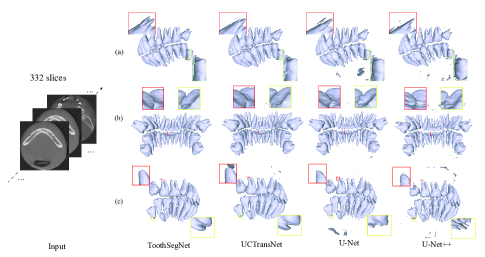
To explore the performance of ToothSegNet in clinics, we employ the marching cubes algorithm [3] to get 3D CBCT mesh. Fig. 5 shows the reconstruction results using four state-of-the-art methods for a selected sample in which CBCT images are blurred around teeth erupting areas, and have high contrast differences as well as significant metal artifacts in teeth crown areas. As is shown in the right view, the tooth root reconstruction of ToothSegNet is the most complete, others have unreasonable disconnected fragments. In the frontal view, ToothSegNet results in the most smooth and natural reconstruction at the tooth connection, whereas UCtransNet leads to unnatural connections, U-Net and U-Net++ both end up with strange textures illustrated in a yellow box and a red box respectively. In the left view, one can observe that the reconstruction of UCTransNet, U-Net, and U-Net++ all contains floating tooth fragments, violating the common sense.
3.4 Ablation study
Table 2 records the ablation study results for the degradation simulation module, structural constraint loss, and the CCF module. One can observe that all three designs are effective for segmentation, calling for the extension of this degradation simulation approach to other computer vision tasks. Also, we compare the performance of the structural constraint loss with the traditional SSIM loss [19] as shown in Fig. 3, demonstrating that our constraint loss leads to preciser segmentation.
| DS | SC | CCF | IoU | Dice | Recall | Precision | |||
|---|---|---|---|---|---|---|---|---|---|
| 90.21 | 94.85 | 97.77 | 92.11 | ||||||
| 89.90 | 94.68 | 97.79 | 91.76 | ||||||
| 89.67 | 94.55 | 97.93 | 91.40 | ||||||
| 88.55 | 93.03 | 97.31 | 90.77 | ||||||
|
|||||||||
4 Conclusion
Accurate tooth CBCT image segmentation is essential for the clinics in orthodontics. In this work, we combine the strengths of the designed degradation simulation module, CCF, and the structure constraint loss to provide a precise and robust automatic CBCT tooth segmentation. With in-depth analysis and ablation study, we show that the proposed ToothSegNet obtains better segmentation results on tooth datasets than the other six advanced medical image segmentation methods in terms of quantitative evaluation and visualization. In the future, we will deploy our work into clinical usage.
References
- [1] Zhiming Cui, Yu Fang, Lanzhuju Mei, Bojun Zhang, Bo Yu, Jiameng Liu, Caiwen Jiang, Yuhang Sun, Lei Ma, Jiawei Huang, et al., “A fully automatic ai system for tooth and alveolar bone segmentation from cone-beam ct images,” Nature communications, vol. 13, no. 1, pp. 1–11, 2022.
- [2] Robert Weiss and Andrew Read-Fuller, “Cone beam computed tomography in oral and maxillofacial surgery: an evidence-based review,” Dentistry journal, vol. 7, no. 2, pp. 52, 2019.
- [3] Jin Hao, Jiaxiang Liu, Jin Li, Wei Pan, Ruizhe Chen, Huimin Xiong, Kaiwei Sun, Hangzheng Lin, Wanlu Liu, Wanghui Ding, et al., “Ai-enabled automatic multimodal fusion of cone-beam ct and intraoral scans for intelligent 3d tooth-bone reconstruction and clinical applications,” arXiv preprint arXiv:2203.05784, 2022.
- [4] Zhiming Cui, Changjian Li, and Wenping Wang, “Toothnet: automatic tooth instance segmentation and identification from cone beam ct images,” in Proceedings of the IEEE/CVF Conference on Computer Vision and Pattern Recognition, 2019, pp. 6368–6377.
- [5] Xiyi Wu, Huai Chen, Yijie Huang, Huayan Guo, Tiantian Qiu, and Lisheng Wang, “Center-sensitive and boundary-aware tooth instance segmentation and classification from cone-beam ct,” in 2020 IEEE 17th International Symposium on Biomedical Imaging (ISBI). IEEE, 2020, pp. 939–942.
- [6] Olaf Ronneberger, Philipp Fischer, and Thomas Brox, “U-net: Convolutional networks for biomedical image segmentation,” in International Conference on Medical image computing and computer-assisted intervention. Springer, 2015, pp. 234–241.
- [7] Zhiming Cui, Bojun Zhang, Chunfeng Lian, Changjian Li, Lei Yang, Wenping Wang, Min Zhu, and Dinggang Shen, “Hierarchical morphology-guided tooth instance segmentation from cbct images,” in International Conference on Information Processing in Medical Imaging. Springer, 2021, pp. 150–162.
- [8] Jie Hu, Li Shen, and Gang Sun, “Squeeze-and-excitation networks,” in Proceedings of the IEEE conference on computer vision and pattern recognition, 2018, pp. 7132–7141.
- [9] Chunwei Tian, Yong Xu, Wangmeng Zuo, Bob Zhang, Lunke Fei, and Chia-Wen Lin, “Coarse-to-fine cnn for image super-resolution,” IEEE Transactions on Multimedia, vol. 23, pp. 1489–1502, 2020.
- [10] Yanting Pei, Yaping Huang, Qi Zou, Xingyuan Zhang, and Song Wang, “Effects of image degradation and degradation removal to cnn-based image classification,” IEEE transactions on pattern analysis and machine intelligence, vol. 43, no. 4, pp. 1239–1253, 2019.
- [11] Haonan Wang, Peng Cao, Jiaqi Wang, and Osmar R Zaiane, “Uctransnet: Rethinking the skip connections in u-net from a channel-wise perspective with transformer,” arXiv preprint arXiv:2109.04335, 2021.
- [12] Zhou Wang, Alan C Bovik, Hamid R Sheikh, and Eero P Simoncelli, “Image quality assessment: from error visibility to structural similarity,” IEEE transactions on image processing, vol. 13, no. 4, pp. 600–612, 2004.
- [13] Shervin Minaee, Yuri Y Boykov, Fatih Porikli, Antonio J Plaza, Nasser Kehtarnavaz, and Demetri Terzopoulos, “Image segmentation using deep learning: A survey,” IEEE transactions on pattern analysis and machine intelligence, 2021.
- [14] Zongwei Zhou, Md Mahfuzur Rahman Siddiquee, Nima Tajbakhsh, and Jianming Liang, “Unet++: A nested u-net architecture for medical image segmentation,” in Deep learning in medical image analysis and multimodal learning for clinical decision support, pp. 3–11. Springer, 2018.
- [15] Jonathan Long, Evan Shelhamer, and Trevor Darrell, “Fully convolutional networks for semantic segmentation,” in Proceedings of the IEEE conference on computer vision and pattern recognition, 2015, pp. 3431–3440.
- [16] Liang-Chieh Chen, George Papandreou, Florian Schroff, and Hartwig Adam, “Rethinking atrous convolution for semantic image segmentation,” arXiv preprint arXiv:1706.05587, 2017.
- [17] Jeya Maria Jose Valanarasu, Poojan Oza, Ilker Hacihaliloglu, and Vishal M Patel, “Medical transformer: Gated axial-attention for medical image segmentation,” in International Conference on Medical Image Computing and Computer-Assisted Intervention. Springer, 2021, pp. 36–46.
- [18] Jiarui Xu, Kai Chen, and Dahua Lin, “Mmsegmenation,” 2020.
- [19] Xuebin Qin, Zichen Zhang, Chenyang Huang, Chao Gao, Masood Dehghan, and Martin Jagersand, “Basnet: Boundary-aware salient object detection,” in Proceedings of the IEEE/CVF conference on computer vision and pattern recognition, 2019, pp. 7479–7489.