PIMCOMP: A Universal Compilation Framework for Crossbar-based PIM DNN Accelerators
Abstract
Crossbar-based PIM DNN accelerators can provide massively parallel in-situ operations. A specifically designed compiler is important to achieve high performance for a wide variety of DNN workloads. However, some key compilation issues such as parallelism considerations, weight replication selection, and array mapping methods have not been solved. In this work, we propose PIMCOMP - a universal compilation framework for NVM crossbar-based PIM DNN accelerators. PIMCOMP is built on an abstract PIM accelerator architecture, which is compatible with the widely used Crossbar/IMA/Tile/Chip hierarchy. On this basis, we propose four general compilation stages for crossbar-based PIM accelerators: node partitioning, weight replicating, core mapping, and dataflow scheduling. We design two compilation modes with different inter-layer pipeline granularities to support high-throughput and low-latency application scenarios, respectively. Our experimental results show that PIMCMOP yields improvements of 1.6 and 2.4 in throughput and latency, respectively, relative to PUMA.
Index Terms:
NVM, PIM accelerator, deep neural network, compilation frameworkI Introduction
In recent years, deep neural networks (DNNs) have made breakthroughs in a variety of tasks. Due to the expansion of the parameter scale of DNN models, the industry expects considerable performance improvements in hardware to efficiently run DNN algorithms. Therefore various DNN accelerators (e.g., [1, 2]) have been proposed. However, these devices based on CMOS and following the von Neumann architecture are now hitting the memory wall challenge [3], and encounter bottlenecks in the improvements of storage, bandwidth, and energy consumption.
Process-in-memory (PIM) is regarded as a promising technology to avoid the memory wall, and has become a popular research direction in the field of DNN accelerators. PIM has a variety of implementations, among which emerging Non-Volatile Memory (NVM) devices such as RRAM, PCM and MRAM have great potential to challenge the dominance of CMOS. Integrating these devices into a 2D cross-point array results in a crossbar array. The 2D crossbar structure formed by NVM devices has attracted growing interest due to its high memory density and parallel in-situ computing properties [4].
There are previous works (e.g., [5, 6, 7, 8, 9]) proposing NVM crossbar-based PIM DNN accelerators. However, they mainly focus on the design of specific architectures and lack consideration of the execution details of DNNs. First, existing works rely on manually mapping the weight data to the crossbars, which ignores the impact of weight mapping on the parallelism of the crossbars and has poor scalability. Second, existing designs often determine the replication of the weights intuitively, such as replicating weight data in early layers to keep the execution pipeline balanced. However, this method does not make effective use of resources. It needs a toolchain to elaborate the task mapping, resource allocation, data distribution, dataflow scheduling, etc., to fully exploit the performance of PIM DNN accelerators when running DNN models. Although PUMA [10] has proposed a compiler for memristor crossbar-based accelerators, it has not effectively solved the problems mentioned above.
To address these limitations, we propose a universal compilation framework, PIMCOMP, for NVM crossbar-based PIM accelerators. The compilation process is divided into 4 phases: node partitioning, weight replicating, core mapping, and dataflow scheduling. Based on these steps, we design a DNN inference compiler. We make the following contributions.
-
•
We propose a general and representative NVM crossbar based accelerator architecture as a hardware abstraction for studying the actual execution of DNNs;
-
•
We provide two compilation modes: “low latency” and “high throughput”, according to the user’s application scenario;
-
•
We propose a genetic algorithm to optimize weight replication and core mapping, with novel fitness function for both compilation modes;
-
•
We design scheduling algorithms to support DNN networks with complex topologies and multiple operators and optimize on-chip memory usage.
II Background and Motivation
II-A NVM Crossbar based DNN Accelerators
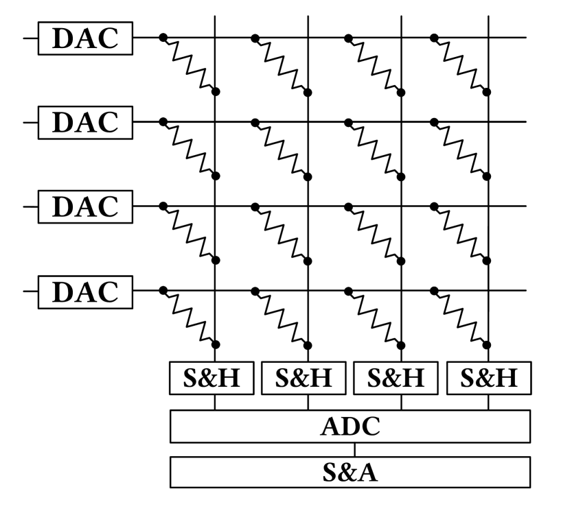
Fig. 1 shows the structure of the NVM crossbar which is the basic operation unit of PIM DNN accelerators. Due to hardware characteristics, NVM crossbars can perform matrix-vector multiplication (MVM) operations efficiently in an analog manner. The conductance of a crossbar cell at each cross-point can be programmed to store an element of matrix G and a voltage vector representing the vector V is applied to the rows. According to Ohm’s law, the current value at each cross-point is , and according to Kirchhoff’s law, the accumulated current value that can be read in each column is . In this way, the crossbar can calculate the dot product of matrix G and vector V in parallel. Since the NVM crossbar operates in the analog domain and other circuits of the accelerator work in the digital domain, peripheral circuits such as ADC/DAC, Sample and Hold (S&H), Shift And Add (S&A) are required in the operation unit.
II-B DNN Compilation Framework
To bridge the gap between various Deep Learning (DL) frameworks and different DL hardwares, several DNN compilation frameworks have been proposed by industry and academia (e.g., [11, 12]).
TVM [11] is a popular end-to-end DL optimization stack that provides multi-stage back-end optimization for different hardwares. However, TVM is not suitable for PIM architectures. First, storage units in PIM are also computation units, which makes the storage and computing characteristics of PIM different from traditional hardware. Second, a significant stage in TVM’s optimization of computing is the scheduling of multi-layer loops, including unrolling, vectorization, parallelization, and tiling. However, the parallel MVM operation is naturally supported by PIM crossbars, so TVM optimization will have limited effects on NVM crossbar-based accelerators.
In the field of PIM, PUMA [10] is the first memristor-based ML inference accelerator that supports ISA with a compiler that can convert high-level languages into ISA code. Nonetheless, heuristic weight replicating and core mapping methods adopted by its compiler are difficult to guarantee high performance. In addition, the granularity of PUMA’s inter-layer pipeline is inference, that is, different layers process data of different inferences, and this processing manner is unacceptable in low-latency scenarios.
III Abstract Accelerator Architecture
We propose an abstract PIM accelerator architecture. On this basis, we propose an execution model to capture the execution characteristics and parallelism of PIM accelerators.
III-A Hardware Abstraction
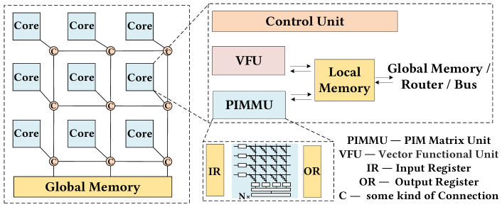
Fig. 2 illustrates the proposed abstract DNN accelerator architecture. At a high level, the accelerator consists of a series of cores connected to a global memory. Each core can be controlled by instructions or state machines. The cores can be interconnected through NoC or busses. The weights of the neural network are stored in the cores, while the inputs, outputs and intermediate results are stored in the global memory. Different cores perform operations asynchronously. Inter-core synchronization occurs when there is an inter-core data transfer.
The abstract core in Fig. 2 consists of a control unit, a local memory and two types of operation units: PIM matrix unit (PIMMU) and vector functional unit (VFU). The PIM matrix unit is composed of several PIM crossbars, which are used to perform MVM operations in the DNN, while the VFU performs other operations, including activation function, pooling, and element-wise operations. The local memory works as a scratchpad that stores inputs and outputs of DNN nodes. The PIMMU and VFU can only access data in the local memory. In addition, operations such as padding, concatenation, and split can also be handled using the local memory.
Our proposed abstract architecture is compatible with the Crossbar/IMA/Tile/Chip structure widely adopted in previous work [5]. This work focuses on the general optimization idea of the compilation process of crossbar-based PIM DNN accelerator, and we do not consider the detailed optimization inside the PIM matrix unit. Nonetheless, related optimizations such as mixed size crossbars [13] and low-bit ADCs [14] are compatible with this abstract architecture.
III-B Execution Model
According to our abstract architecture, after mapping the DNN to the cores, each core can get a static operation sequence, which is composed of the basic operations such as MVM, VEC, COMM, and MEM, representing MVM operations by PIMMU, vector operations by VFU, communication between cores, and access to global memory, respectively. We do not restrict the format of the operation sequence. It can be a series of instructions, or a schedule of basic operators, etc.
For any two MVMs in the operation sequence of the same core, the parallel relationship between them is analyzed as follows.
-
•
If they are for the same crossbar, that is, there is a structural conflict between them, the latter one must wait for the previous one to complete before it can start.
-
•
If the input data of the latter MVM is the output of the former one, that is, there is a data dependency between them, the latter one must also wait for the former MVM to finish before it can start.
For several MVM operations that do not have structural conflicts, data dependencies, and synchronization blocking at a certain moment, the start time interval between two adjacent MVM operations is determined by the on-chip bandwidth of each core.
IV Compilation Framework
IV-A The Overview of PIMCOMP
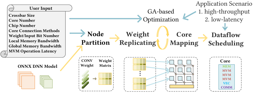
Fig. 3 illustrates the high-level overview of PIMCOMP. First, PIMCOMP reads the user input and loads DNN model in ONNX format which facilitates conversion between different DL frameworks, and obtains the model description including node (in this work, node and layer share the same meaning) information and topological relationship after parsing the model. This information will be fed to the backend. The entire backend includes 4 stages. Node Partitioning (Section IV-B) describes the rules for dividing the convolutional and fully connected layers according to the crossbar size. Weight Replicating (Section IV-C) determines the replication numbers of different nodes, Core Mapping (Section IV-C) decides the mapping relationship between crossbars and cores, and Dataflow Scheduling (Section IV-D) performs scheduling and optimization according to user’s requirement to generate control flow or instruction flow.
We provide two compilation modes for users to choose from: High Throughput (HT) and Low Latency (LL), which are suitable for scenarios with continuous input data of large batches and intermittent input of a small amount of data, respectively. Their main design difference is the granularity of the inter-layer pipeline. In HT mode, DNN processes in a layer-by-layer manner. When the pipeline is filled, different layers process data from different inferences. There is no inter-layer data communication so parallelism between layers is high. In LL mode, as long as one layer produces an output, it passes the output to the position required by subsequent layers. When a layer receives enough data, it can start its operation, so the overall latency is low.
IV-B Node Partitioning
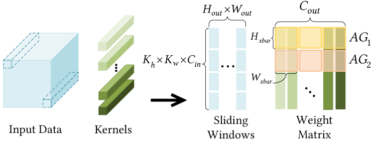
Due to the limited size of a crossbar array, weight data of convolutional layers and fully connected layers cannot be completely mapped to the same crossbar in general, so we need to partition these nodes to fit in the crossbars. Node partitioning strategy is shown in Fig. 4. First, the convolutional layers and fully connected layers (which can be regarded as special convolutional layers) in DNN are converted into MVM operations. Specifically, the weights of each convolution kernel are flatten into a column, thus obtaining a weight matrix with height and width , where , represent the width and height of the convolution kernel and , represent the number of input channels and output channels, respectively. After that, the entire weight matrix is divided into several Array Groups (AG) according to the size of the crossbar array. The height of each AG is equal to the height of the crossbar array , and the width is equal to . Therefore each AG contains crossbar arrays, where is the width of crossbar array. Each AG needs to run input cycles (input sliding windows), where and are the height and width of the output feature.
It is preferred to map all crossbars of one AG to the same core. Crossbar arrays belonging to the same AG can be driven by the same instruction or control signal, therefore gathering them in one core can reduce control complexity. More importantly, these crossbar arrays have the exact same input. If they are in the same core, input data can be broadcast to these arrays, which avoids repeatedly accessing Input Register and alleviates on-chip bandwidth and buffer pressure.
After partitioning the weight, the AGs need to be allocated to the cores. One core may contain AGs of multiple nodes, and AGs of one node may be mapped to different cores. The MVM results obtained by AGs of the same node need to be accumulated to get a complete computation result. If AGs of the same node are mapped to different cores, data accumulation across cores is required.
IV-C Weight Replicating and Core Mapping
The storage units in PIM are also computation units, so an important way to improve computation parallelism is to replicate the weight data multiple times. Besides, allocating computing tasks among cores also greatly influences performance of PIM accelerators, taking into account structural conflict and data dependency. The above two steps are intertwined so we employ a modified genetic algorithm to optimize them simultaneously.
IV-C1 Algorithm Design
In the genetic algorithm, each gene represents several AGs of a node, which is encoded as an integer, expressed as . For example, represents AGs of the node. To ensure that the mapping result is not so scattered that on-chip communication becomes a bottleneck, we set a limit on the number of nodes that each core can hold, . Therefore, the chromosome length of each individual is , where is user specified. The location of each gene in the chromosome determines the index of core these AGs are mapped to. This encoding takes into account flexibility and operational efficiency. If each AG is coded, the chromosome will be too long to process efficiently.
In the initialization phase, we randomly select the replication number for each node, and randomly map the AGs to the cores. The design of the fitness function is directly related to the optimization effect, which will be described in the following subsection. Crossover phase in this issue lacks practical significance, so we skip it. Mutation is an important phase to improve resource utilization and inference performance. In this stage, the algorithm will randomly select individuals to perform one of the following four mutation operations: I. Randomly select a node, increase its replication number, and randomly map the expanded AG to cores. II. Randomly select a node, reduce its replication number, and recover the crossbar arrays occupied by that replicated block. III. Randomly select a gene and spread its AG to other cores. IV. Randomly select a gene and merge its AG into the same node of other cores.
IV-C2 Fitness Function
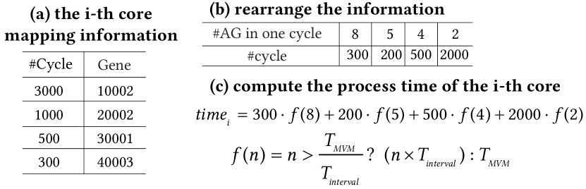
For HT mode, the overall inference time can directly reflect the performance. Fig. 5 is an example of how to calculate the estimated inference time of the i-th core in HT mode. A total of 4 nodes are mapped to the i-th core, containing , , , and AGs respectively, and the AGs of each node have , , , and input sliding windows respectively. Because there is no data dependency between AGs, each AG starts to execute in turn at interval under the condition that no structural conflict occurs. Rearrange the information to get the table in Fig. 5(b). The in the first column means that the number of AGs in this core is for the first operation cycles. After cycles, the 4-th node is completed, so the number of AGs for the next cycles is . Based on this information, the estimated time of the i-th core can be calculated according to the formula in Fig. 5(c). calculates the operation time of one operation cycle when there are AGs in the core. If , where is the time to complete a single MVM operation, then each operation cycle takes ; otherwise . In this way, an ideal inference time is calculated for each core, so the fitness function for HT mode is .
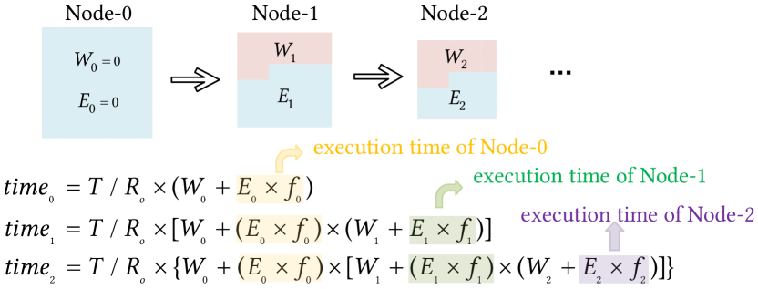
For LL mode, the inter-layer execution sequence in LL mode can be equivalent to “after waiting for the provider node (layer) to generate enough output, the consumer node (layer) starts to execute and generates all outputs without pause”. This waiting percentage can be calculated for each node. Further, if the uninterrupted execution time of node is and if the replication number of node is times that of its consumer node , it takes for the consumer node to complete the calculation without pausing after waiting . Therefore the overall time to complete computing these two nodes is .
The estimated runtime of LL mode can be derived as shown in Fig. 6. For convenience, we set , where is the replication number of the node and gets the provider node index of node . We let , which represents the percentage of execution of node . We assume the execution time of the first node without extra replication is . Iterate based on topology and the final estimated time is used as the fitness function .
IV-D Dataflow Scheduling
The dataflow scheduling stage will generate a sequence of instructions or control flow according to the pipeline mode selected by the user. We first introduce the dataflow scheduling algorithms in HT mode and LL mode, and then describe the on-chip memory optimization technique.
IV-D1 HT Dataflow
Algorithm 1 shows dataflow scheduling for HT mode. It is unrealistic to store all data in a inference of each node in on-chip local memory so it is necessary to periodically transfer some input (output) data from (to) the global memory to (from) the local memory (Lines 3 and 9). In the inter-core data accumulation process (Line 7), AGs are required to transfer the data to be accumulated to the core where the first AG of this replicated weight block is located. To improve parallelism, other operations such as POOL, CONCAT, ELTWISE are distributed among several cores (Line 10). DNNs with complex topology are easy to implement in HT mode with each node reading the corresponding data from global memory.
IV-D2 LL Dataflow
In LL mode, each node computes an output and then immediately passes it to its consumer nodes. When one node receives enough input, it can start executing. The condition for the output of node to start computing is that the node has received the last input [15] that it requires, and can be formulated as:
where and are the height and width of the output feature of node , respectively. , , and are kernel size, stride, and padding size of node , respectively, if node is convolutional or pooling layer.
According to the formula, the required input and expected output of each replicated block can be obtained. In order to improve computational parallelism and reduce the transmission between cores, other operations in DNN are divided into several cores according to the replication number of their predecessor convolutional layer.
IV-D3 On-Chip Memory Reuse
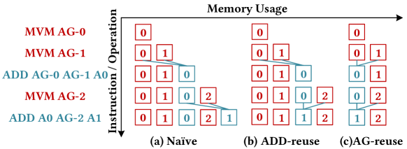
Since the capacity of on-chip local memory is limited and global memory access is expensive, efficient utilization of on-chip local memory is important to reduce the frequency of accessing global memory, improve executing efficiency and reduce power consumption. Fig. 7 illustrates an example of memory optimization. For the naive method, we allocate new memory block for each operation. Most memory blocks are accessed once and will never be used again. So we use an ADD-reuse in Fig. 7(b) to reuse the memory for data accumulation. But allocating memory blocks for each AG still causes a lot of waste. Therefore, we propose AG-reuse on the basis of ADD-reuse in Fig. 7(c), which fully reuses the on-chip storage of AGs.
V Evaluation
V-A Experiment Setup
V-A1 hardware characteristics
In order to evaluate the performance of PIMCOMP and facilitate fair comparison, we adopt PUMA architecture to instantiate our design. The PIM material is ReRAM, and NoC is selected as core connection implementation. Our evaluation adopts the same parameters as PUMA, including area and power information of ReRAM crossbars, VFUs, and control units. The ReRAM cell precision is 2-bit, and inputs, outputs and weights are 16-bit fixed-point numbers. Memory modules and routers are modeled by CACTI [16] and Orion 3.0 [17] respectively, to get energy and area estimation. The detailed configurations of hardware are summarized in Table I.
| Component | Parameters | Specification |
|
|
||||
| PIMMU | # crossbar | 64 | 1221.76 | 0.77 | ||||
| VFU | # per core | 12 | 22.80 | 0.048 | ||||
| Local Memory | capacity | 64 kB | 18.00 | 0.085 | ||||
| Control Unit | — | — | 8.00 | 0.11 | ||||
| Core | # per chip | 36 | 1270.56 | 1.01 | ||||
| Router | flit size | 64 | 43.13 | 0.14 | ||||
| Global Memory | capacity | 4 MB | 257.72 | 2.42 | ||||
| Hyper Transport | link bandwidth | 6.40 GB/s | 10.40 k | 22.88 | ||||
| Chip | — | — | 56.79 k | 62.92 |
V-A2 benchmarks and baselines
We use both computationally intensive network (vgg16) and topologically complex networks (resnet18, squeezenet, googlenet and inception-v3) as benchmarks. We build a cycle-accurate simulator. It accepts the operation stream compiled by PIMCOMP, and can simulate the structure conflict and data dependency of MVM operation, the usage of on-chip local memory, the synchronization overhead of inter-core communication and can obtain energy consumption and area overhead.
As a comparison, we faithfully implement the PUMA dataflow under our framework and it is called a PUMA-like dataflow. According to [10, 18], the purpose of node replicating is to balance the pipeline and a heuristic method is adopted to deal with core mapping. Since PUMA only support dataflow with pipeline granularity of inference (HT mode), we implement the LL mode for PUMA.
V-B Experimental Result
V-B1 Throughput and Latency
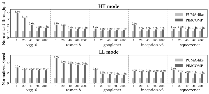
Fig. 8 shows the results of throughput and latency of PIMCOMP under different degrees of parallelism. The degree of parallelism here refers to how many AGs are allowed to calculate at the same time, limited by the user given on-chip bandwidth. According to the results, we can observe that with the increase of parallelism, the improvement of PIMCOMP gradually decreases. This is because the source of optimization is the gap between the actual performance and the ideal performance of the hardware. Still, PIMCOMP gains and improvements in throughput and latency, respectively, relative to PUMA.
In HT mode, the optimization effect of googlenet and squeezenet is limited. The main reason is that the MVM calculation pressure of these networks is light, so the time to access global memory and to process vector and memory operations become dominant. For computationally intensive tasks such as vgg16, PIMCOMP can achieve better optimization effect. In LL mode, the optimization effect of PIMCOMP is more significant because the node replicating method adopted by PUMA is not efficient enough.
V-B2 Energy
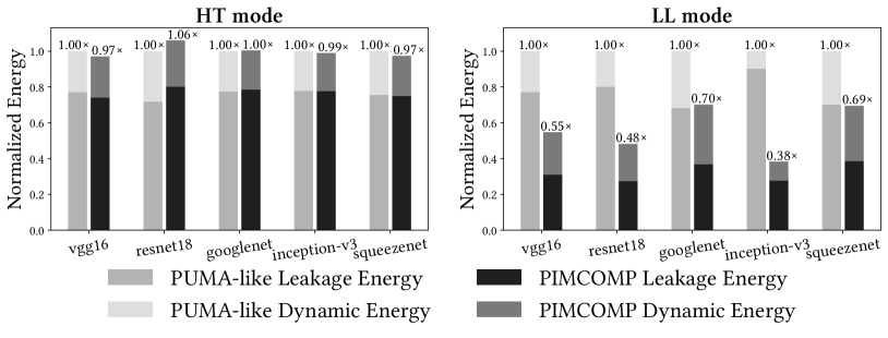
Fig. 9 shows the energy evaluation results with parallelism degree . The computational load of the same network is relatively fixed so dynamic energy of PUMA and PIMCOMP are close. The main difference between two compilation results is static energy consumption. In HT mode, PUMA allocates computation unevenly, causing some cores to run for a long time while others finish early. PIMCOMP ensures the computing tasks are evenly distributed. This results in a slight increase in static energy due to having more cores active, although PIMCOMP has a shorter overall runtime. In LL mode, there is data dependency between cores, and the active time of each core is related to the overall inference time. PIMCOMP is able to reduce static energy by by reducing overall runtime.
V-B3 Memory Usage
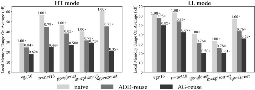
Fig. 10 shows the effect of different memory reuse optimization. In the evaluation of HT mode, every core will transfer results back to global memory and load new input data into local memory after each AG performs 2 MVM operations. In HT mode, if AG-reuse is adopted, the global memory access can be reduced by an average of compared with the naive method. This will result in faster inference speed and lower memory access energy consumption. In LL mode, the average local memory usage can be controlled within 64kB using AG-reuse optimization, which is in line with our architectural design.
V-B4 Compiling Time
| vgg16 | resnet18 | googlenet | squeezenet | inception_v3 | ||||||
| HT | LL | HT | LL | HT | LL | HT | LL | HT | LL | |
| Node Partitioning | 0.01 | 0.01 | 0.04 | 0.03 | 0.04 | 0.04 | 0.05 | 0.05 | 0.03 | 0.03 |
| Replicating+Mapping | 8.93 | 1.80 | 12.39 | 6.35 | 12.90 | 8.10 | 12.04 | 7.43 | 12.88 | 8.76 |
| Dataflow Scheduling | 1.62 | 6.67 | 0.54 | 4.39 | 0.64 | 5.44 | 1.08 | 32.72 | 0.80 | 20.78 |
| Total | 10.56 | 8.48 | 12.96 | 10.78 | 13.57 | 13.58 | 13.17 | 40.21 | 13.71 | 29.57 |
Table II shows the running time of PIMCOMP. The population size is and the maximum iteration number is in the genetic algorithm. We can observe that weight replicating and core mapping take longer time in HT mode, while dataflow scheduling is time-consuming in LL mode. The overall compiling time is acceptable.
VI Conclusion
Previous research studies on NVM crossbar based PIM accelerator downplay several practical issues, such as parallelism consideration, weight replication selection and array mapping methods. In this work, we propose PIMCOMP, which has 4 general optimization stages to form a complete compilation toolchain for PIM accelerators. Evaluations show that our work outperforms a PUMA-like compiler on average in terms of performance and power consumption. PIMCOMP is orthogonal to other studies on PIM accelerators, and researchers can apply PIMCOMP to their accelerators for further improvement.
References
- [1] T. Chen et al., “Diannao: A small-footprint high-throughput accelerator for ubiquitous machine-learning,” in ASPLOS, p. 269–284, 2014.
- [2] Y.-H. Chen et al., “Eyeriss: A spatial architecture for energy-efficient dataflow for convolutional neural networks,” in ISCA, pp. 367–379, 2016.
- [3] S.-L. Lu et al., “Scaling the “memory wall”: Designer track,” in ICCAD, pp. 271–272, 2012.
- [4] I. Chakraborty et al., “Resistive crossbars as approximate hardware building blocks for machine learning: Opportunities and challenges,” Proceedings of the IEEE, vol. 108, no. 12, pp. 2276–2310, 2020.
- [5] A. Shafiee et al., “Isaac: A convolutional neural network accelerator with in-situ analog arithmetic in crossbars,” in ISCA, pp. 14–26, 2016.
- [6] X. Qiao et al., “Atomlayer: A universal reram-based cnn accelerator with atomic layer computation,” in DAC, pp. 1–6, 2018.
- [7] T. Song et al., “Brahms: Beyond conventional rram-based neural network accelerators using hybrid analog memory system,” in DAC, pp. 1033–1038, 2021.
- [8] S. Jung et al., “A crossbar array of magnetoresistive memory devices for in-memory computing,” Nature, vol. 601, pp. 211–216, Jan 2022.
- [9] A. Chen et al., “Enabling high-performance dnn inference accelerators using non-volatile analog memory (invited),” in EDTM, pp. 1–4, 2020.
- [10] A. Ankit et al., “Puma: A programmable ultra-efficient memristor-based accelerator for machine learning inference,” in ASPLOS, p. 715–731, 2019.
- [11] T. Chen et al., “Tvm: An automated end-to-end optimizing compiler for deep learning,” in OSDI, (USA), p. 579–594, 2018.
- [12] N. Vasilache et al., “Tensor comprehensions: Framework-agnostic high-performance machine learning abstractions,” 2018.
- [13] Z. Zhu et al., “Mixed size crossbar based rram cnn accelerator with overlapped mapping method,” in ICCAD, pp. 1–8, 2018.
- [14] Y. He et al., “Infox: An energy-efficient reram accelerator design with information-lossless low-bit adcs,” in DAC, p. 97–102, 2022.
- [15] Z. Zhu et al., “Mnsim 2.0: A behavior-level modeling tool for memristor-based neuromorphic computing systems,” in GLSVLSI, p. 83–88, 2020.
- [16] R. Balasubramonian et al., “Cacti 7: New tools for interconnect exploration in innovative off-chip memories,” ACM Trans. Archit. Code Optim., vol. 14, jun 2017.
- [17] A. B. Kahng et al., “Orion3.0: A comprehensive noc router estimation tool,” IEEE Embedded Systems Letters, vol. 7, no. 2, pp. 41–45, 2015.
- [18] J. Ambrosi et al., “Hardware-software co-design for an analog-digital accelerator for machine learning,” in ICRC, pp. 1–13, 2018.