SynthCal: A Synthetic Benchmarking Pipeline to Compare Camera Calibration Algorithms
Abstract
Accurate camera calibration is crucial for various computer vision applications. However, measuring camera parameters in the real world is challenging and arduous, and there needs to be a dataset with ground truth to evaluate calibration algorithms’ accuracy. In this paper, we present SynthCal, a synthetic camera calibration benchmarking pipeline that generates images of calibration patterns to measure and enable accurate quantification of calibration algorithm performance in camera parameter estimation. We present a SynthCal-generated calibration dataset with four common patterns, two camera types, and two environments with varying view, distortion, lighting, and noise levels. The dataset evaluates single-view calibration algorithms by measuring reprojection and root-mean-square errors for identical patterns and camera settings. Additionally, we analyze the significance of different patterns using Zhang’s method, which estimates intrinsic and extrinsic camera parameters with known correspondences between 3D points and their 2D projections in different configurations and environments. The experimental results demonstrate the effectiveness of SynthCal in evaluating various calibration algorithms and patterns.
Index Terms— camera calibration, benchmarking, synthetic dataset, pattern recognition
1 Introduction
When we capture an image using a camera, the captured digital image can differ from the real-world scene in terms of perspective, distortion, color, resolution, and other visual properties. This is because real-world scenes are three-dimensional and continuous, while digital images captured by a camera are two-dimensional and discrete, and contain distortion and other imperfections. To minimize thse differences and improve the accuracy of image-based computer vision tasks, camera calibration is essential.
Camera calibration involves calculating camera parameters that refer to its intrinsic and extrinsic characteristics for accurately mapping points in the 3D world to their corresponding 2D image coordinates. Once the camera is calibrated, it can accurately measure distances, angles, and sizes of objects in the 3D world and perform other image-based computer vision tasks such as object tracking [1], 3D reconstruction [2], augmented reality [3], medical imaging [4], and autonomous driving [5].
Geometric camera calibration [6] is one of the most widely used calibration methods. It involves using a calibration target with known geometric features, such as a calibration grid, to estimate the camera parameters. The target is captured from different angles, and the resulting images are used to estimate the camera parameters that minimize the difference between the predicted and observed image points.
However, creating a real camera calibration data with ground truth for calibration algorithms can be challenging because it is difficult to measure camera position and rotation accurately, and the camera’s intrinsic parameters can change with changes in the zoom level, focus distance, or temperature. Additionally, the aging of the camera or misalignment of its components can also affect the intrinsic parameters. Moreover, cameras can have different intrinsic parameters, even if they are of the same make and model, because of manufacturing tolerances, assembly errors, and differences in lens quality. Observing the calibration pattern in the image along with the previous knowledge of the pattern, we can determine the intrinsic and extrinsic parameters using various calibration algorithms, such as Zhang’s calibration method [7], the Tsai’s method [8], or Bouguet method [9]. Previous works have tried to compare different camera calibration algorithms [10, 11, 12, 13]. However, there is a need for a benchmarking procedure that can provide a quantitative comparison of calibration algorithms due to the unknown ground truth of the calibration dataset.
To overcome these problems, we introduce the SynthCal pipeline, which generates a synthetic camera calibration dataset with user-defined intrinsic camera parameters while precisely measuring the extrinsic camera parameters. It enables the selection of the optimal camera calibration algorithm for specific configurations by considering all intrinsic, extrinsic, and distortion parameters. It also ensures that lighting conditions and noise are identical for the different captured datasets for accurate comparison. The idea of generating synthetic calibration data has been previously applied in other works, such as sports-based synthetic calibration [14] and evaluating closed-form solutions of principal line calibration [15], but not necessarily for comparing calibration algorithms.
Our main contributions can be summarized as follows:
-
•
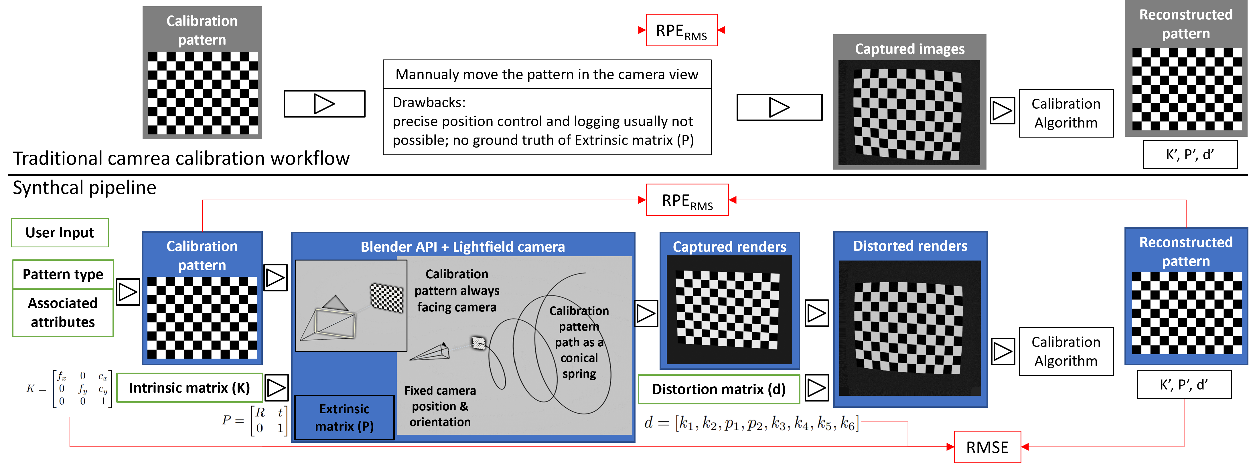
We present a pipeline to generate a camera calibration dataset with ground truth parameters and select the optimal camera calibration algorithm for the specific configurations, as depicted in Fig. 1.
-
•
We evaluate the proposed pipeline on three different camera calibration algorithms and four different calibration patterns using a SynthCal-generated dataset with 1016 images, two distinct camera configurations, and two different lighting and noise conditions.
2 Proposed Method
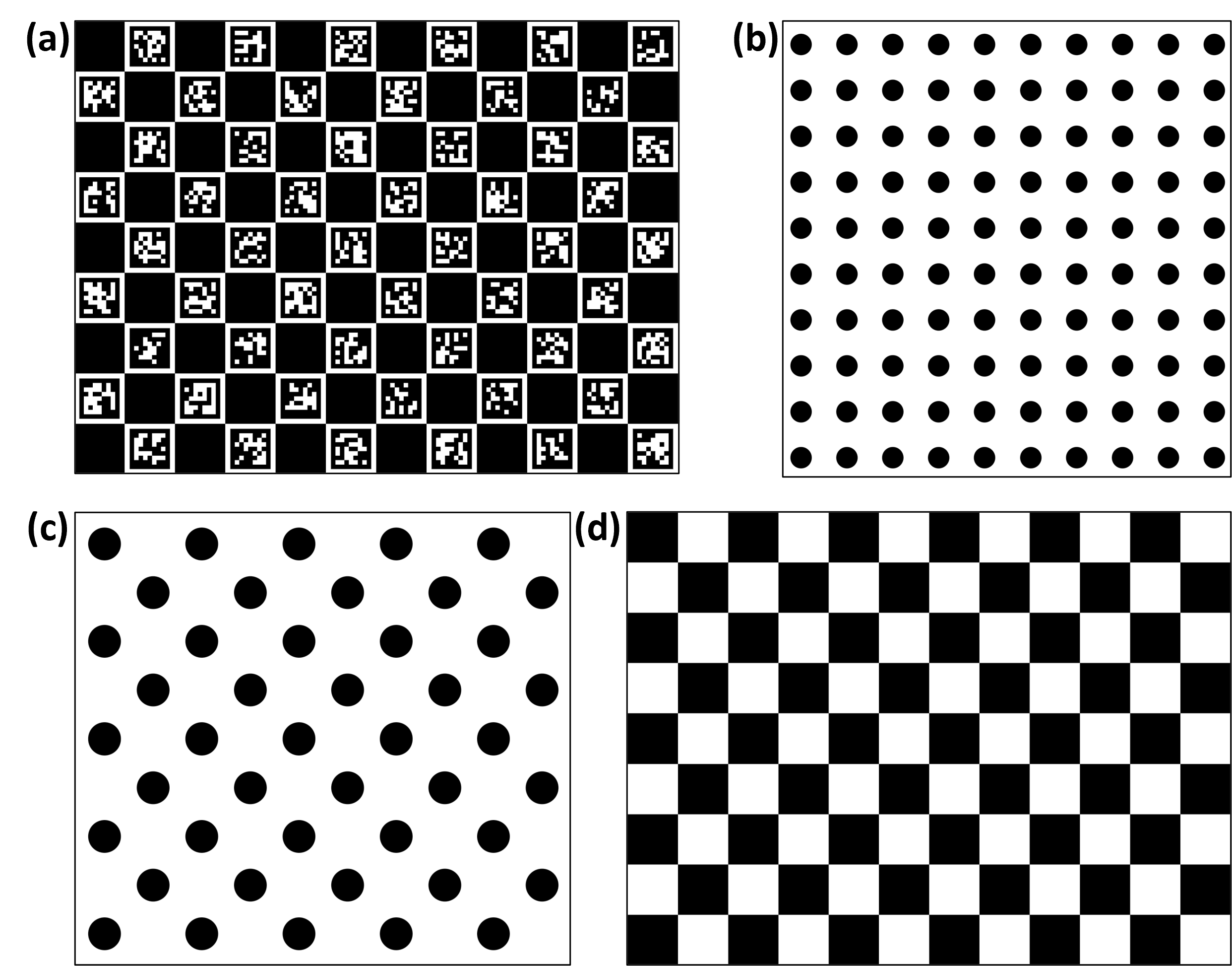
We created a modular web-based interface with OpenCV [16] and Blender API [17] in the back-end to generate a synthetic camera calibration dataset with ground truth which has functionalities to create different camera calibration patterns, simulate a camera inside Blender using the light-field analysis add-on [18], render the camera calibration pattern from various positions and orientations, add radial distortions while establishing the camera’s intrinsic, extrinsic and distortion parameters to formulate the ground truth. We used an OpenCV script to generate geometric patterns that take input pattern type, and pattern attributes to generate a PNG image. Our script allows us to create checkerboard patterns (Ch), symmetric circular patterns (Sc), asymmetric circular patterns (Ac), and Charuco[19] patterns (Cu) of different configurations as shown in Fig. 1. Let be the intrinsic matrix of the camera, which includes the parameters that describe the internal configuration of the camera, such as the focal length (, ) and principal point (, ):
| (1) |
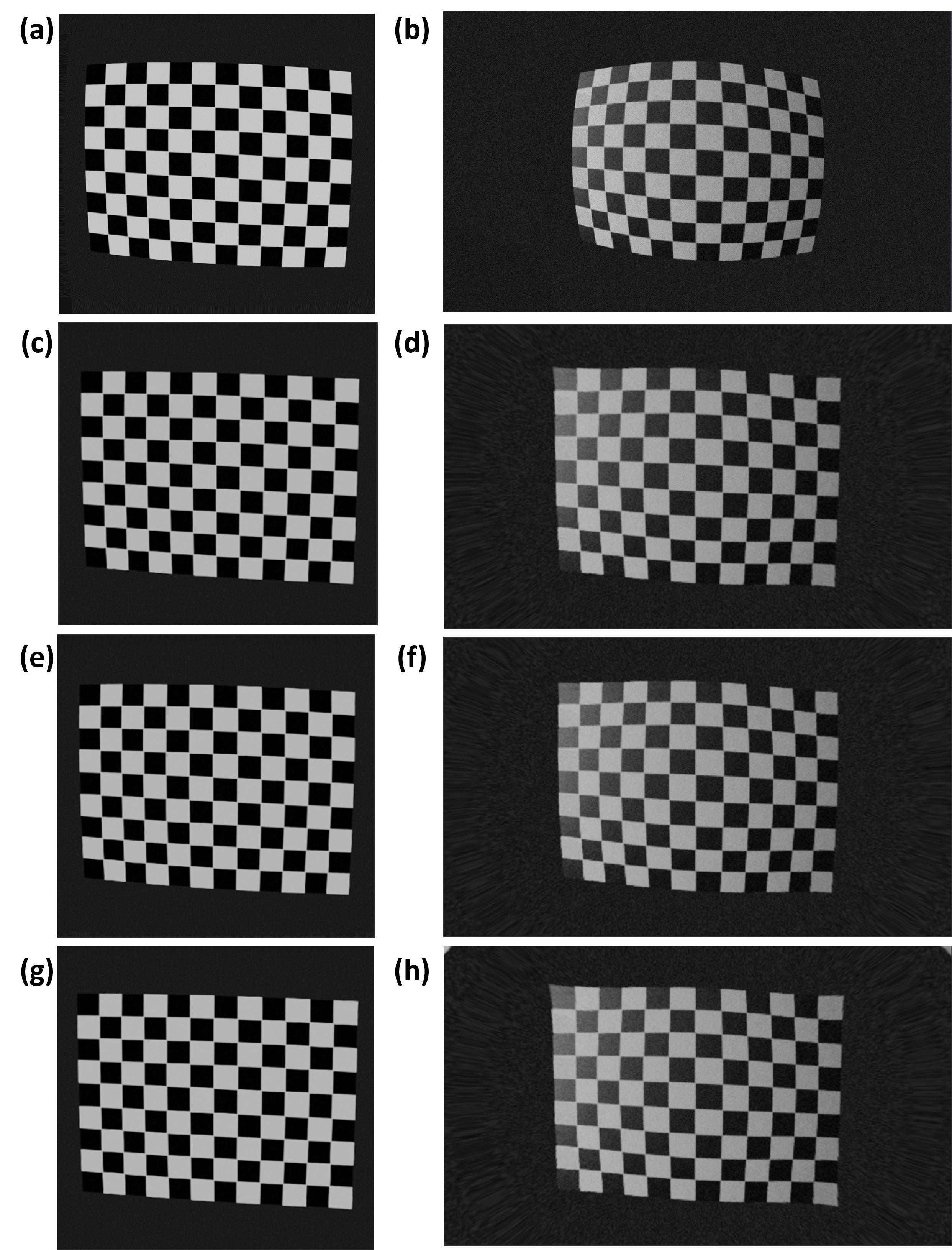
We used a Blender python API and a light-field add-on to create a synthetic camera that takes camera attributes (, ) and (, ) to create a camera configuration file for simulating the camera inside Blender. To capture the calibration pattern for dataset creation, we moved the pattern in a path resembling the shape of a conical spring, as depicted in Fig. 1. The center of the calibration pattern is always in the camera’s direction, so the planar pattern can be captured in different angles, sizes, and orientations and have consistency without going out of the camera frame. Let be the rotation matrix that describes the orientation of the camera in the global coordinate system, and let be the translation vector that describes the position of the camera in the world coordinate system:
| (2) |
The extrinsic matrix combines the rotation matrix and the translation vector. is, and are evaluated by extracting the global position and orientation of the camera and calibration pattern at each frame. The camera parameters can also be described using the distortion parameters, which describe the deviations from the ideal imaging system. The distortion parameters can be represented as a vector
| (3) |
where are radial distortion coefficients and are tangential distortion coefficients. The distortions are added later using Blender undistorted node by setting up a tracking scene in Blender and defining and . The final equation for mapping a 3D point in the global coordinate system to a 2D point in the image plane, including the distortion parameters, can be written as:
| (4) |
Where and are the distorted image coordinates, the distortion model maps the distorted image coordinates to the corrected image coordinates. The captures are saved in PNG formats, while camera parameters are saved as NumPy arrays.
3 Results and Evaluation
3.1 Dataset
We created a dataset of four widely used distinct pattern types that are a 912 checkerboard pattern with a checker width of 15 mm, one 1010 symmetric circle pattern with 7 mm circle diameter, and 15 mm circle spacing, one 910 asymmetric circle pattern with 9 mm diameter, and 22 mm diagonal spacing and 912 Charuco pattern checker width of 15 mm and ArUco dictionary [20] of 77. Two distinct camera configurations representing a high-resolution rectilinear lens with focal length (, ), principal point (, ) with distortion parameters and a low resolution wide, angle lens with focal length (, ), principal point (, ) with distortion parameters are simulated for capturing the patterns. Skew and tangential distortion are kept at zero for both camera configurations. The extrinsic parameters a 33 identity matrix and a 31 zero vector are calculated using vector calculation with the relative position and orientation of the camera and target pattern to establish the ground truth. Two different external lighting conditions are used while rendering, one with uniform light across the scene without noise and another with Directional lights with additive Gaussian noise in the camera captures. We created eight data configurations with 127 captures with camera intrinsic and extrinsic matrix for each configuration as specified in the Table 1.
| Camera | Pattern | Environment |
|---|---|---|
| 912 Ch | ||
| Rectilinear | 1010 Sc | Uniform light |
| lens. | 910 Ac | and no noise. |
| 912 Cu | ||
| 912 Ch | ||
| Wide angle | 1010 Sc | Directional light and |
| lens. | 910 Ac | Gaussian noise. |
| 912 Cu |
3.2 Evaluation & Analysis
We used () as a metric to compare the algorithms and calibration patterns which can be defined as:
| (5) |
where is the number of points, is the observed image point in the captured image, and is the corresponding projected image point using the estimated intrinsic and extrinsic parameters from the camera calibration. We also calculated accuracy by comparing the estimated intrinsic and extrinsic parameters of the camera to the ground truth values using () that can be defined as:
| (6) |
where is the number of parameters being estimated, is the ground truth value for the -th parameter, and is the estimated value for the -th parameter. We evaluated three different single-view camera calibration algorithms for both rectilinear and wide-angle camera configurations with the dataset created using 912 checkerboard pattern and listed in Table 2.
| Camera | Algorithm | ||
|---|---|---|---|
| Rectilinear | Zhang’s method | 0.510 | 1.221 |
| lens. | Tsai’s method | 0.551 | 1.880 |
| Bouguet method | 0.373 | 1.127 | |
| Wide angle | Zhang’s method | 1.316 | 2.219 |
| lens. | Tsai’s method | 1.433 | 2.344 |
| Bouguet method | 0.811 | 1.861 |
To compare different camera calibration patterns, we calculated both and for all eight available configurations using Zhang’s method, which is listed in Table 3.
Based on the results of we observed that and are low for the high-resolution rectilinear camera with uniform lighting and no additive noise, unlike the wide-angle camera with low distortion, directional light, Gaussian noise, and high distortion factors. Both scores follow a similar trend and verify that our work aligns with the pre-established effectiveness of different calibration methods in different circumstances [10]. we also observed that center-based patterns are more efficient than edge-based patterns in austere environments. However, increased complexity makes their performance worse than the edge-based patterns. The Charuco pattern with the best score proves its robustness to noise compared to other patterns.
| Environment | Pattern | ||
|---|---|---|---|
| 912 Ch | 0.510 | 1.221 | |
| Uniform light | 1010 Sc | 0.508 | 1.206 |
| and no noise. | 910 Ac | 0.506 | 1.205 |
| 912 Cu | 0.493 | 1.093 | |
| 912 Ch | 1.116 | 2.219 | |
| Directional light | 1010 Sc | 1.20 | 2.263 |
| and Gaussian noise. | 910 Ac | 1.118 | 2.261 |
| 912 Cu | 0.898 | 1.916 |
4 Conclusion
In this paper, we presented SynthCal, a comprehensive pipeline for generating customized camera-specific calibration datasets that can be used to benchmark different camera calibration algorithms and patterns. By introducing ground truth parameters, the proposed pipeline enables the comparison of different calibration algorithms using not only pixel-wise reprojection error but also a new RMSE of intrinsic and extrinsic parameters. This allows us to select the optimal calibration strategy for any given camera configuration. We generated calibration datasets with four distinct calibration patterns and evaluated three calibration methods for two camera configurations. The quantitative results are consistent with previous works, but the proposed approach has a broader scope. In future work, the proposed SynthCal pipeline can be easily modified for multi-view and non-planar calibration algorithms for any camera type.
5 Acknowledgments
The research reported in this paper was supported by the BMBF (German Federal Ministry of Education and Research) in the project VidGenSense (01IW21003).
References
- [1] Mustansar Fiaz, Arif Mahmood, Sajid Javed, and Soon Ki Jung, “Handcrafted and deep trackers: Recent visual object tracking approaches and trends,” ACM Computing Surveys (CSUR), vol. 52, no. 2, pp. 1–44, 2019.
- [2] Zhizhong Kang, Juntao Yang, Zhou Yang, and Sai Cheng, “A review of techniques for 3d reconstruction of indoor environments,” ISPRS International Journal of Geo-Information, vol. 9, no. 5, pp. 330, 2020.
- [3] Mark Roman Miller, Hanseul Jun, Fernanda Herrera, Jacob Yu Villa, Greg Welch, and Jeremy N Bailenson, “Social interaction in augmented reality,” PloS one, vol. 14, no. 5, pp. e0216290, 2019.
- [4] Inés Barbero-García, José Luis Lerma, Pablo Miranda, and Ángel Marqués-Mateu, “Smartphone-based photogrammetric 3d modelling assessment by comparison with radiological medical imaging for cranial deformation analysis,” Measurement, vol. 131, pp. 372–379, 2019.
- [5] Di Feng, Lars Rosenbaum, Claudius Glaeser, Fabian Timm, and Klaus Dietmayer, “Can we trust you? on calibration of a probabilistic object detector for autonomous driving,” arXiv preprint arXiv:1909.12358, 2019.
- [6] Juho Kannala, Janne Heikkilä, and Sami S Brandt, “Geometric camera calibration.,” Wiley encyclopedia of computer science and engineering, vol. 13, no. 6, pp. 1–20, 2008.
- [7] Zhengyou Zhang, “A flexible new technique for camera calibration,” IEEE Transactions on pattern analysis and machine intelligence, vol. 22, no. 11, pp. 1330–1334, 2000.
- [8] Roger Tsai, “A versatile camera calibration technique for high-accuracy 3d machine vision metrology using off-the-shelf tv cameras and lenses,” IEEE Journal on Robotics and Automation, vol. 3, no. 4, pp. 323–344, 1987.
- [9] J-Y Bouguet, “Camera calibration toolbox for matlab,” http://www. vision. caltech. edu/bouguetj/calib_doc/index. html, 2004.
- [10] Helmut Zollner and Robert Sablatnig, Comparison of methods for geometric camera calibration using planar calibration targets, na, 2004.
- [11] Psang D Lin and Chi K Sung, “Comparing two new camera calibration methods with traditional pinhole calibrations,” Optics Express, vol. 15, no. 6, pp. 3012–3022, 2007.
- [12] Derek D Lichti and Changjae Kim, “A comparison of three geometric self-calibration methods for range cameras,” Remote Sensing, vol. 3, no. 5, pp. 1014–1028, 2011.
- [13] Jan Hieronymus, “Comparison of methods for geometric camera calibration,” International Archives of the Photogrammetry, Remote Sensing and Spatial Information Sciences, vol. 39, pp. 595–599, 2012.
- [14] Jianhui Chen and James J Little, “Sports camera calibration via synthetic data,” in Proceedings of the IEEE/CVF conference on computer vision and pattern recognition workshops, 2019, pp. 0–0.
- [15] Jen-Hui Chuang, Chih-Hui Ho, Ardian Umam, Hsin-Yi Chen, Jenq-Neng Hwang, and Tai-An Chen, “Geometry-based camera calibration using closed-form solution of principal line,” IEEE Transactions on Image Processing, vol. 30, pp. 2599–2610, 2021.
- [16] Gary Bradski, “The opencv library.,” Dr. Dobb’s Journal: Software Tools for the Professional Programmer, vol. 25, no. 11, pp. 120–123, 2000.
- [17] Blender Online Community, Blender - a 3D modelling and rendering package, Blender Foundation, Stichting Blender Foundation, Amsterdam, 2023.
- [18] Katrin Honauer, Ole Johannsen, Daniel Kondermann, and Bastian Goldluecke, “A dataset and evaluation methodology for depth estimation on 4d light fields,” in Computer Vision–ACCV 2016: 13th Asian Conference on Computer Vision, Taipei, Taiwan, November 20-24, 2016, Revised Selected Papers, Part III 13. Springer, 2017, pp. 19–34.
- [19] Gwon Hwan An, Siyeong Lee, Min-Woo Seo, Kugjin Yun, Won-Sik Cheong, and Suk-Ju Kang, “Charuco board-based omnidirectional camera calibration method,” Electronics, vol. 7, no. 12, pp. 421, 2018.
- [20] Grigorios Tzortzis and Aristidis Likas, “The minmax k-means clustering algorithm,” Pattern recognition, vol. 47, no. 7, pp. 2505–2516, 2014.