Hybrid Precoder and Combiner Designs for Decentralized Parameter Estimation in mmWave MIMO Wireless Sensor Networks

Priyanka Maity   Suraj Srivastava   Kunwar Pritiraj Rajput   Naveen K. D. Venkategowda   Aditya K. Jagannatham   and Lajos Hanzo L. Hanzo would like to acknowledge the financial support of the Engineering and Physical Sciences Research Council projects EP/W016605/1 and EP/X01228X/1 as well as of the European Research Council’s Advanced Fellow Grant QuantCom (Grant No. 789028). The work of Aditya K. Jagannatham was supported in part by the Qualcomm Innovation Fellowship, and in part by the Arun Kumar Chair Professorship.P. Maity, S. Srivastava and A. K. Jagannatham are with the Department of Electrical Engineering, Indian Institute of Technology, Kanpur, Kanpur, 208016, India (e-mail: pmaity@iitk.ac.in, ssrivast@iitk.ac.in, adityaj@iitk.ac.in.)K. P. Rajput was with the Department of Electrical Engineering, Indian Institute of Technology, Kanpur, Kanpur, 208016, India. He is now with the interdisciplinary center of security reliability and trust (SnT), University of Luxembourg, 4365, Luxembourg (e-mail: kunwar.rajput@uni.lu) N. K. D. Venkategowda is with the Department of Science and Technology, Linköping University, 60174 Norrköping, Sweden (e-mail: naveen.venkategowda@liu.se.)L. Hanzo is with the School of Electronics and Computer Science, University of Southampton, Southampton SO17 1BJ, U.K. (e-mail: lh@ecs.soton.ac.uk)
Abstract

Hybrid precoder and combiner designs are conceived for decentralized parameter estimation in millimeter wave (mmWave) multiple-input multiple-output (MIMO) wireless sensor networks (WSNs). More explicitly, efficient pre- and post-processing of the sensor observations and received signal are proposed for the minimum mean square error (MMSE) estimation of a parameter vector. The proposed techniques exploit the limited scattering nature of the mmWave MIMO channel for formulating the hybrid transceiver design framework as a multiple measurement vectors (MMV)-based sparse signal recovery problem. This is then solved using the iterative appealingly low-complexity simultaneous orthogonal matching pursuit (SOMP). Tailor-made designs are presented for WSNs operating under both total and per-sensor power constraints, while considering ideal noiseless as well as realistic noisy sensors. Furthermore, both the Bayesian Cramer-Rao lower bound and the centralized MMSE bound are derived for benchmarking the proposed decentralized estimation schemes. Our simulation results demonstrate the efficiency of the designs advocated and verify the analytical findings.

Index Terms:
Hybrid transceiver design, mmWave MIMO, wireless sensor networks, majorization theory, decentralized parameter estimation

I Introduction

Recent advances in massive Machine-Type Communication (mMTC) and low cost of sensors have opened new opportunities for deploying large scale wireless sensor networks (WSNs) [1]. This has ushered in a new era and paved the way for compelling applications, such as the Internet of Things (IoT) [2] [3]. This in turn enables various applications of substantial socio-economic value, such as health care [4], agriculture [5], defence [6], smart cities [7], smart grids [8], vehicle-to-everything (V2X) communication [9], among others. In a typical WSN that performs decentralized estimation [10],[11], [12] the constituent low-power sensors precode the observations followed by transmission to a fusion center (FC) over a coherent multiple access channel (MAC). The FC subsequently processes the received data for generating reliable estimates of the multiple parameters under consideration. In contrast, centralized estimation refers to the scenario when all the sensor measurements are available directly at the FC without any distortion. Naturally, the estimation accuracy in WSNs is generally degraded by both the measurement/observation noise at the sensors, as well as by the fading nature of the wireless channel and also by the ubiquitous thermal noise of the communication circuitry at the FC. Therefore, conceiving powerful precoder/combiner designs capable of exploiting the multiplexing and diversity gains of the multiple-input multiple-output (MIMO) WSN is of crucial importance for achieving reliable estimates of the parameters. Unfortunately, the massive connectivity required by the large number of sensors in a large-scale IoT deployment further exacerbates the spectrum crunch in the over-crowded sub-6 GHz band. This motivates leveraging the less congested, but higher path loss spectrum beyond the current sub-6 GHz bands.

Millimeter wave (mmWave) wireless technology, which exploits the abundant spectrum available in the mmWave band (30-300 GHz), can help realize the dual goals of massive connectivity and high data rates necessary to support WSNs [13], [14], [15]. However, communication in the mmWave band is challenging due to its high propagation losses and severe signal blockage [16],[17]. In such a scenario, multiple antenna technology can be leveraged to overcome these barriers, which is especially convenient in mmWave frequency bands owing to the short wavelength that supports the fabrication and integration of a very large number of antennas in compact devices. However, it must be noted that the large number of antennas at both ends necessitates a large number of radio-frequency (RF) chains, since the conventional baseband transceiver architecture requires an individual RF chain for each antenna. This leads to unsustainably high power consumption, especially by the analog-to-digital converters (ADCs) [18] that are required to operate at high sampling rates due to the high bandwidth of signals in the mmWave frequency bands. To overcome this problem, the hybrid RF-baseband transceiver architecture, proposed in the pioneering contributions [19], [20] offers an excellent solution for the practical realization of mmWave MIMO systems. Hence, we focus our attention on designing novel hybrid precoder/combiner designs for decentralized parameter vector estimation in mmWave MIMO WSNs. Next we discuss other novel contributions on linear decentralized estimation.

I-A State-of-the-Art in Transceiver Designs for WSNs

The popular model of linear decentralized estimation has been developed in the seminal works in [10], [11] and [21]. However, the signal processing techniques proposed therein are unsuitable in mmWave MIMO-based WSNs, given the specific nature of signal processing at mmWave frequencies. Specifically, for mmWave MIMO systems, analog beamforming [17] is a compellingly low-complexity, low-power technique. However, its impediment is that it does not readily support multi-stream transmission, which is critical for the simultaneous estimation of multiple parameters. As a remedy, hybrid beamforming techniques have been proposed in [20], which simultaneously support both spatial multiplexing and transmission of multiple streams in mmWave MIMO systems. The hybrid transceiver employed in such systems is comprised of an RF precoder consisting of a digitally controlled network of phase shifters and a baseband precoder relying on a digital signal processor (DSP). Similarly, the hybrid combiner at the receiver is comprised of an analog RF combiner in cascade with a digital baseband combiner. For designing the hybrid transceiver components, Ayach et al. [20] proposed an interesting hybrid transmit precoder (TPC)/ receive combiner (RC) design for mutual information maximization in a point-to-point mmWave MIMO system. The conventional fully-digital optimal precoder obtained therein is the right singular matrix of the mmWave MIMO channel matrix. The authors then decompose the fully-digital TPC into its RF and baseband components using the low-complexity simultaneous orthogonal matching pursuit (SOMP) algorithm incorporating the properties of the mmWave channel model. However, in a coherent MAC-based mmWave MIMO WSN, the design of the fully-digital TPC is a non-trivial problem. Yu et al. [22] formulated the hybrid precoder design paradigm as a matrix factorization problem, and developed an alternating minimization (Altmin) algorithm for solving it. The iterative algorithm presented therein has a significantly higher complexity and does not exploit the specific properties of the mmWave MIMO channel. Gong et al. [23] proposed hybrid transceiver designs based on majorization-minimization (MM) method. The other various hybrid precoder and combiner designs for cellular mmWave MIMO systems are described in works such as [24, 25, 26, 27, 28]. Furthermore, Wang et al. [29] addressed the security aspect and designed a hybrid precoder for securing broadcast communications in mmWave IoT networks. Hybrid beamforming was also considered by Chae et al. [30] for simultaneous wireless information and power transfer (SWIPT) based IoT sensor networks where the nodes were considered working only in half-duplex mode.

TABLE I: Boldly contrasting our new contributions against the state-of-the-art
Attribute [20], [21], [24], [25] [22] [28] [29], [30] [31] [33] [34] Proposed
mmWave MIMO WSN
Decentralized Estimation
Coherent MAC
Vector Parameter Estimation
Hybrid Transceiver Design
Closed-form Solution
MSE-optimal
Total Power Budget
Individual Sensor Power Constraints

However, authors therein have not exploited the properties of the mmWave MIMO channel and considered a single antenna at the FC for scalar parameter estimation, hence they were unable to glean any multiplexing gain for improving the estimation accuracy. Zhao et al. [31] also proposed a hybrid precoding scheme for SWIPT based IoT nodes in a Rayleigh fading channel working in full-duplex mode. Lie et al. [32] presented a hybrid TPC design based on the alternating direction method of multipliers (ADMM) for the maximization of mutual information in an orthogonal MAC. However, the estimation accuracy in a WSN is best quantized in terms of the mean square error (MSE) of parameter estimation, which cannot be represented by a mutual information based objective function. The authors of [33] presented a MMSE-based transceiver optimization procedure for multi-user MIMO systems, where the optimal TPCs are obtained by minimizing the sum MSE subject to a constraint on the total power of all the users. However, it must be noted that their scheme cannot be used in WSNs since the system model of a MIMO WSN is substantially different to that of a multi user MIMO cellular system. In an uplink multi-user MIMO system, each user transmits its data symbol to the base station, which is independent of the data symbols of the other users. Therefore, the data transmitted from the kth user suffers from interference arising due to the other co-channel users. By contrast, in a WSN, all the sensors simultaneously observe correlated versions of the same parameter. Thus, the observation vectors transmitted from the sensors are correlated and noisy versions of the parameter have to be estimated. Moreover, it can be readily inferred from [33] that in a multi-user MIMO system, the TPCs {𝐓¯k}k=1Ksuperscriptsubscriptsubscript¯𝐓𝑘𝑘1𝐾\left\{\overline{\mathbf{T}}_{k}\right\}_{k=1}^{K} corresponding to the K𝐾K users are decoupled in the sum-MSE expression. However, in the corresponding sum-MSE expression of the MIMO WSN, the TPCs {𝐅k}k=1Ksuperscriptsubscriptsubscript𝐅𝑘𝑘1𝐾\left\{{\mathbf{F}}_{k}\right\}_{k=1}^{K} corresponding to the K𝐾K sensors are coupled, as will be seen in Section III. This necessitates a completely different algorithm for the design of the TPCs, which is described in our paper. Authors in [34] have proposed ADMM-based iterative hybrid transceiver designs in MIMO WSNs. However, the work does not exploit the mmWave channel sparsity for hybrid transceiver designs. Rajput et al. [35] have proposed hybrid precoder designs for scalar parameter estimation in mmWave MIMO WSNs. However, to the best of our knowledge, none of the existing contributions have developed a hybrid transceiver design taking into account the associated power constraints of the parameter vector estimation problem of a mmWave hybrid MIMO WSN, which is hence the objective of this treatise. The contributions of this work are described in the next section. Furthermore, the novel aspects of this paper are boldly and explicitly contrasted to the existing literature in Table I.

I-B Our Contributions

  • Novel TPC/ RC designs are developed for decentralized parameter vector estimation in mmWave MIMO WSNs. Our hybrid analog-digital transceiver designs are first designed for a scenario associated with noisy measurements under a given total power budget. Subsequently, hybrid TPCs are designed for a mmWave hybrid MIMO WSN subject to individual power constraints at the constituent sensors, which are suitable for applications where each sensor has a stringent power budget due to its limited battery charge.

  • Closed-form expressions are derived for the optimal fully-digital TPCs using majorizaton theory. Subsequently, the hybrid baseband and RF TPC components are designed using SOMP.

  • For parameter estimation at the FC, both a fully-digital RC, and its baseband and RF components are derived by minimizing the MSE using the classic linear minimum mean square error (LMMSE) framework.

  • Both, the Bayesian Cramer-Rao bound (BCRB) and the centralized MMSE bound are derived for benchmarking the MSE performance of parameter estimation in the proposed designs relying on noiseless and noisy sensor observations, respectively.

  • Our simulation results confirm that the proposed schemes perform close to the fully-digital designs having as many RF chains as the number of antennas, and they approach the centralized MMSE lower bound at high signal-to-noise ratio (SNR), hence illustrating their efficiency.

I-C Outline of the paper

The rest of the paper is outlined as follows. Section II discusses the mmWave hybrid MIMO WSN system model and the mmWave MIMO channel model of linear decentralized parameter estimation. Section III presents MSE-optimal hybrid TPC/ RC designs, initially under a total power budget and individual sensor power constraints. Our simulation results are discussed in Section V, and we conclude in Section VI. For maintaining seamless flow, the proofs of the various propositions are relegated to the Appendices.

Notation: Small and capital boldface letters 𝐳𝐳\mathbf{z} and 𝐙𝐙\mathbf{Z} have been used to represent vectors and matrices, respectively. ()Tsuperscript𝑇()^{T}, ()Hsuperscript𝐻()^{H} and ()superscript()^{\dagger} denote transpose, Hermitian transpose and pseudo-inverse operations respectively; Furthermore, the (i,j)𝑖𝑗(i,j)th element of a matrix 𝐙𝐙\mathbf{Z} is denoted by 𝐙(i,j)𝐙𝑖𝑗\mathbf{Z}(i,j); A block diagonal matrix is denoted by blkdiag(𝐙1,𝐙2,,𝐙L)blkdiagsubscript𝐙1subscript𝐙2subscript𝐙𝐿\mathrm{blkdiag}(\mathbf{Z}_{1},\mathbf{Z}_{2},\ldots,\mathbf{Z}_{L}) where the matrices 𝐙1subscript𝐙1\mathbf{Z}_{1}, 𝐙2subscript𝐙2\mathbf{Z}_{2} upto 𝐙Lsubscript𝐙𝐿\mathbf{Z}_{L} are on its principal diagonal; Furthermore, diag(𝐙)diag𝐙\mathbf{\mathrm{diag}\left(\mathbf{Z}\right)} and 𝝀(𝐙)𝝀𝐙\mathbf{\boldsymbol{\lambda}\left(\mathbf{Z}\right)} denote the vector of diagonal elements and vector of eigenvalues of a matrix 𝐙𝐙\mathbf{Z} respectively; λk(𝐙)subscript𝜆𝑘𝐙\mathbf{{\lambda}}_{k}\left(\mathbf{Z}\right) and σk(𝐙)subscript𝜎𝑘𝐙\mathbf{{\sigma}}_{k}\left(\mathbf{Z}\right) represent the k𝑘kth eigenvalue and k𝑘kth singular value of the matrix 𝐙𝐙\mathbf{Z}, respectively; The column-space and row-space of matrix 𝐙𝐙\mathbf{Z} are denoted by 𝒞(𝐙)𝒞𝐙\mathcal{C}(\mathbf{Z}) and (𝐙)𝐙\mathcal{R}(\mathbf{Z}), respectively; The operator (z)+superscript𝑧\left(z\right)^{+} denotes max{z,0}max𝑧0\text{max}\left\{z,0\right\}; 𝒞𝒩(0,1)𝒞𝒩01\mathcal{CN}(0,1) denotes a standard complex normal distributed random variable with mean 00 and variance 111.

Refer to caption
Figure 1: Coherent MAC based mmWave MIMO WSN system model

II mmWave Hybrid MIMO WSN System Model

This section describes the mmWave hybrid MIMO WSN system model and the mmWave MIMO channel model of linear decentralized estimation.

II-A mmWave MIMO WSN Model

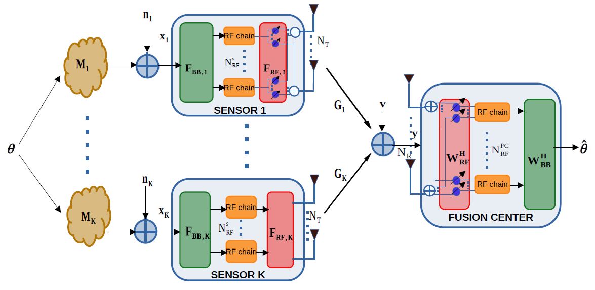
The mmWave WSN, as depicted in Fig. 1, consists of K𝐾K sensors each having NTsubscript𝑁𝑇N_{T} antennas, and NRFssuperscriptsubscript𝑁RF𝑠N_{\text{RF}}^{s} RF chains and a FC equipped with NRsubscript𝑁𝑅N_{R} antennas and NRFFCsuperscriptsubscript𝑁RFFCN_{\text{RF}}^{\text{FC}} RF chains, where NRFFCNRmuch-less-thansuperscriptsubscript𝑁RFFCsubscript𝑁𝑅N_{\text{RF}}^{\text{FC}}\ll N_{R} and NRFsNTmuch-less-thansuperscriptsubscript𝑁RF𝑠subscript𝑁𝑇N_{\text{RF}}^{s}\ll N_{T}. Each sensor simultaneously senses the common parameter vector 𝜽m×1𝜽superscript𝑚1\boldsymbol{\theta}\in{\mathbb{C}}^{m\times 1}, where 𝜽𝒞𝒩(𝟎,𝐑θ)similar-to𝜽𝒞𝒩0subscript𝐑𝜃\boldsymbol{\theta}\sim\mathcal{CN}(\mathbf{0},\mathbf{R}_{\theta}). The observations 𝐱kqk×1subscript𝐱𝑘superscriptsubscript𝑞𝑘1{\mathbf{x}}_{k}\in{\mathbb{C}}^{q_{k}\times 1} at the k𝑘kth sensor can be modelled as

𝐱k=𝐌k𝜽+𝐧k.subscript𝐱𝑘subscript𝐌𝑘𝜽subscript𝐧𝑘\displaystyle{\mathbf{x}}_{k}={\mathbf{M}}_{k}\boldsymbol{\theta}+{\mathbf{n}}_{k}. (1)

The quantity 𝐌kqk×msubscript𝐌𝑘superscriptsubscript𝑞𝑘𝑚{\mathbf{M}}_{k}\in{\mathbb{C}}^{q_{k}\times m} denotes the measurement matrix of the k𝑘kth sensor, while qksubscript𝑞𝑘q_{k} represents the number of measurements sensed by the k𝑘kth sensor. Here 𝐧kqk×1subscript𝐧𝑘superscriptsubscript𝑞𝑘1{\mathbf{n}}_{k}\in{\mathbb{C}}^{q_{k}\times 1} represents the circularly symmetric complex additive Gaussian observation noise at the k𝑘kth sensor with zero mean and covariance matrix 𝐑n,kqk×qksubscript𝐑𝑛𝑘superscriptsubscript𝑞𝑘subscript𝑞𝑘\mathbf{R}_{n,k}\in\mathbb{C}^{q_{k}\times q_{k}}.

As per the hybrid TPC scheme, the observation vector is precoded initially by the baseband TPC 𝐅BB,kNRFs×qksubscript𝐅BB𝑘superscriptsuperscriptsubscript𝑁RF𝑠subscript𝑞𝑘\mathbf{F}_{\text{BB},k}\in{\mathbb{C}}^{N_{\text{RF}}^{s}\times q_{k}} followed with the RF TPC 𝐅RF,kNT×NRFssubscript𝐅RF𝑘superscriptsubscript𝑁𝑇superscriptsubscript𝑁RF𝑠\mathbf{F}_{\text{RF},k}\in{\mathbb{C}}^{N_{T}\times N_{\text{RF}}^{s}} of the k𝑘kth sensor. The RF TPC is realized exclusively using equal-gain phase shifters, and performs analog processing in the RF domain to achieve a beamforming gain. Therefore, the magnitudes of the elements of RF TPC can be constrained as |𝐅RF,k(s,t)|=1NTsubscript𝐅RF𝑘𝑠𝑡1subscript𝑁𝑇|\mathbf{F}_{\text{RF},k}(s,t)|=\frac{1}{\sqrt{N_{T}}}. The mmWave MIMO channel between the k𝑘kth sensor and the FC is denoted by 𝐆kNR×NTsubscript𝐆𝑘superscriptsubscript𝑁𝑅subscript𝑁𝑇{\mathbf{G}}_{k}\in{\mathbb{C}}^{N_{R}\times N_{T}}. Thus, the signal received by the FC can be expressed as

𝐲𝐲\displaystyle{\mathbf{y}} =k=1K𝐆k𝐅RF,k𝐅BB,k𝐱k+𝐯absentsuperscriptsubscript𝑘1𝐾subscript𝐆𝑘subscript𝐅RF𝑘subscript𝐅BB𝑘subscript𝐱𝑘𝐯\displaystyle=\sum_{k=1}^{K}{\mathbf{G}}_{k}{\mathbf{F}}_{\text{RF},k}{\mathbf{F}}_{\text{BB},k}{\mathbf{x}}_{k}+{\mathbf{v}}
=k=1K𝐆k𝐅RF,k𝐅BB,k𝐌k𝜽+k=1K𝐆k𝐅RF,k𝐅BB,k𝐧k+𝐯absentsuperscriptsubscript𝑘1𝐾subscript𝐆𝑘subscript𝐅RF𝑘subscript𝐅BB𝑘subscript𝐌𝑘𝜽superscriptsubscript𝑘1𝐾subscript𝐆𝑘subscript𝐅RF𝑘subscript𝐅BB𝑘subscript𝐧𝑘𝐯\displaystyle=\sum_{k=1}^{K}{\mathbf{G}}_{k}{\mathbf{F}}_{\text{RF},k}{\mathbf{F}}_{\text{BB},k}{\mathbf{M}}_{k}\boldsymbol{\theta}+\sum_{k=1}^{K}{\mathbf{G}}_{k}{\mathbf{F}}_{\text{RF},k}{\mathbf{F}}_{\text{BB},k}{\mathbf{n}}_{k}+{\mathbf{v}}
=𝐆𝐅𝐌𝜽+𝐆𝐅𝐧+𝐯,absent𝐆𝐅𝐌𝜽𝐆𝐅𝐧𝐯\displaystyle={\mathbf{G}}{\mathbf{F}}{\mathbf{M}}\boldsymbol{\theta}+{\mathbf{G}}{\mathbf{F}}\mathbf{n}+{\mathbf{v}}, (2)

where 𝐯NR×1𝐯superscriptsubscript𝑁𝑅1\mathbf{v}\in{\mathbb{C}}^{N_{R}\times 1} is the FC noise, which is distributed as 𝐯𝒞𝒩(𝟎,𝐑v)similar-to𝐯𝒞𝒩0subscript𝐑𝑣\mathbf{v}\sim\mathcal{CN}(\mathbf{0},\mathbf{R}_{v}), where 𝐑v=σv2𝐈NRsubscript𝐑𝑣superscriptsubscript𝜎𝑣2subscript𝐈subscript𝑁𝑅\mathbf{R}_{v}=\sigma_{v}^{2}\mathbf{I}_{N_{R}}. The stacked observation matrix 𝐌q×m𝐌superscript𝑞𝑚\mathbf{M}\in{\mathbb{C}}^{q\times m}, and the concatenated channel matrix 𝐆NR×KNT𝐆superscriptsubscript𝑁𝑅𝐾subscript𝑁𝑇\mathbf{G}\in{\mathbb{C}}^{N_{R}\times KN_{T}} across the sensors, are defined as

𝐌𝐌\displaystyle\mathbf{M} =[𝐌1T,𝐌2T,,𝐌KT]T,𝐆=[𝐆1,𝐆2,,𝐆K],formulae-sequenceabsentsuperscriptsuperscriptsubscript𝐌1𝑇superscriptsubscript𝐌2𝑇superscriptsubscript𝐌𝐾𝑇𝑇𝐆subscript𝐆1subscript𝐆2subscript𝐆𝐾\displaystyle=\left[\mathbf{M}_{1}^{T},\mathbf{M}_{2}^{T},\cdots,\mathbf{M}_{K}^{T}\right]^{T},\mathbf{G}=\left[\mathbf{G}_{1},\mathbf{G}_{2},\cdots,\mathbf{G}_{K}\right], (3)

where k=1Kqk=qsuperscriptsubscript𝑘1𝐾subscript𝑞𝑘𝑞\sum_{k=1}^{K}q_{k}=q. The block-diagonal hybrid TPC 𝐅KNT×q𝐅superscript𝐾subscript𝑁𝑇𝑞\mathbf{F}\in{\mathbb{C}}^{KN_{T}\times q} is given by

𝐅=𝐅RF𝐅BB,𝐅subscript𝐅RFsubscript𝐅BB\mathbf{F}=\mathbf{F}_{\text{RF}}\mathbf{F}_{\text{BB}}, (4)

where 𝐅RFKNT×KNRFssubscript𝐅RFsuperscript𝐾subscript𝑁𝑇𝐾superscriptsubscript𝑁RF𝑠{\mathbf{F}_{\text{RF}}}\in\mathbb{C}^{KN_{T}\times KN_{\text{RF}}^{s}} is the block-diagonal RF TPC and 𝐅BBKNRFs×qsubscript𝐅BBsuperscript𝐾superscriptsubscript𝑁RF𝑠𝑞\mathbf{F}_{\text{BB}}\in\mathbb{C}^{KN_{\text{RF}}^{s}\times q} is the block-diagonal baseband TPC, which are defined as

𝐅RF=blkdiag(𝐅RF,1,𝐅RF,2,,𝐅RF,K),subscript𝐅RFblkdiagsubscript𝐅RF1subscript𝐅RF2subscript𝐅RF𝐾\displaystyle\mathbf{F}_{\text{RF}}=\mathrm{blkdiag}(\mathbf{F}_{\text{RF},1},\mathbf{F}_{\text{RF},2},\cdots,\mathbf{F}_{\text{\text{RF}},K}), (5)
𝐅BB=blkdiag(𝐅BB,1,𝐅BB,2,,𝐅BB,K).subscript𝐅BBblkdiagsubscript𝐅BB1subscript𝐅BB2subscript𝐅BB𝐾\displaystyle\mathbf{F}_{\text{BB}}=\mathrm{blkdiag}(\mathbf{F}_{\text{BB},1},\mathbf{F}_{\text{BB},2},\cdots,\mathbf{F}_{\text{BB},K}). (6)

Furthermore, the covariance matrix 𝐑nq×qsubscript𝐑𝑛superscript𝑞𝑞\mathbf{R}_{n}\in{\mathbb{C}}^{q\times q} of the concatenated observation noise vector 𝐧=[𝐧1T,𝐧2T,,𝐧KT]Tq×1𝐧superscriptsuperscriptsubscript𝐧1𝑇superscriptsubscript𝐧2𝑇superscriptsubscript𝐧𝐾𝑇𝑇superscript𝑞1\mathbf{n}=[\mathbf{n}_{1}^{T},\mathbf{n}_{2}^{T},\cdots,\mathbf{n}_{K}^{T}]^{T}\in\mathbb{C}^{q\times 1} is given by

𝐑n=blkdiag(𝐑n,1,𝐑n,2,,𝐑n,K).subscript𝐑𝑛blkdiagsubscript𝐑𝑛1subscript𝐑𝑛2subscript𝐑𝑛𝐾\displaystyle\mathbf{R}_{n}=\mathrm{blkdiag}(\mathbf{R}_{n,1},\mathbf{R}_{n,2},\cdots,\mathbf{R}_{n,K}). (7)
Refer to caption
Figure 2: Spatial channel model for the mmWave MIMO system
𝜽^^𝜽\displaystyle\widehat{\boldsymbol{\theta}} =𝐖BBH𝐖RFH(k=1K𝐆k𝐅RF,k𝐅BB,k𝐌k)𝜽+𝐖BBH𝐖RFH(k=1K𝐆k𝐅RF,k𝐅BB,k𝐧k)+𝐖BBH𝐖RFH𝐯absentsuperscriptsubscript𝐖BB𝐻superscriptsubscript𝐖RF𝐻superscriptsubscript𝑘1𝐾subscript𝐆𝑘subscript𝐅RF𝑘subscript𝐅BB𝑘subscript𝐌𝑘𝜽superscriptsubscript𝐖BB𝐻superscriptsubscript𝐖RF𝐻superscriptsubscript𝑘1𝐾subscript𝐆𝑘subscript𝐅RF𝑘subscript𝐅BB𝑘subscript𝐧𝑘superscriptsubscript𝐖BB𝐻superscriptsubscript𝐖RF𝐻𝐯\displaystyle=\mathbf{W}_{\text{BB}}^{H}\mathbf{W}_{\text{RF}}^{H}\Bigg{(}\sum_{k=1}^{K}{{\mathbf{G}}_{k}\mathbf{F}_{\text{RF},k}\mathbf{F}_{\text{BB},k}{\mathbf{M}}_{k}}\Bigg{)}\boldsymbol{\theta}+\mathbf{W}_{\text{BB}}^{H}\mathbf{W}_{\text{RF}}^{H}\left(\sum_{k=1}^{K}{{\mathbf{G}}_{k}\mathbf{F}_{\text{RF},k}\mathbf{F}_{\text{BB},k}{\mathbf{n}}_{k}}\right)+\mathbf{W}_{\text{BB}}^{H}\mathbf{W}_{\text{RF}}^{H}\mathbf{v}
=𝐖BBH𝐖RFH𝐆𝐅𝐌𝜽+𝐖BBH𝐖RFH𝐆𝐅𝐧+𝐖BBH𝐖RFH𝐯=𝐖H𝐆𝐅𝐌𝜽+𝐖H𝐆𝐅𝐧+𝐖H𝐯.absentsuperscriptsubscript𝐖BB𝐻superscriptsubscript𝐖RF𝐻𝐆𝐅𝐌𝜽superscriptsubscript𝐖BB𝐻superscriptsubscript𝐖RF𝐻𝐆𝐅𝐧superscriptsubscript𝐖BB𝐻superscriptsubscript𝐖RF𝐻𝐯superscript𝐖𝐻𝐆𝐅𝐌𝜽superscript𝐖𝐻𝐆𝐅𝐧superscript𝐖𝐻𝐯\displaystyle=\mathbf{W}_{\text{BB}}^{H}\mathbf{W}_{\text{RF}}^{H}{\mathbf{G}}{\mathbf{F}}{\mathbf{M}}\boldsymbol{\theta}+\mathbf{W}_{\text{BB}}^{H}\mathbf{W}_{\text{RF}}^{H}{\mathbf{G}}{\mathbf{F}}\mathbf{n}+\mathbf{W}_{\text{BB}}^{H}\mathbf{W}_{\text{RF}}^{H}\mathbf{v}=\mathbf{W}^{H}{\mathbf{G}}{\mathbf{F}}{\mathbf{M}}\boldsymbol{\theta}+\mathbf{W}^{H}{\mathbf{G}}{\mathbf{F}}\mathbf{n}+\mathbf{W}^{H}\mathbf{v}. (8)

The parameter estimate 𝜽^m×1^𝜽superscript𝑚1\widehat{\boldsymbol{\theta}}\in{\mathbb{C}}^{m\times 1} at the FC of the unknown parameter 𝜽𝜽\boldsymbol{\theta} is obtained using the hybrid RC denoted by 𝐖𝐖\mathbf{W}, which can be decomposed as 𝐖=𝐖RF𝐖BB𝐖subscript𝐖RFsubscript𝐖BB\mathbf{W}=\mathbf{W}_{\text{RF}}\mathbf{W}_{\text{BB}}, where 𝐖RFNR×NRFFCsubscript𝐖RFsuperscriptsubscript𝑁𝑅superscriptsubscript𝑁RFFC\mathbf{W}_{\text{RF}}\in\mathbb{C}^{N_{R}\times N_{\text{RF}}^{\text{FC}}} is the RF RC and 𝐖BBNRFFC×msubscript𝐖BBsuperscriptsuperscriptsubscript𝑁RFFC𝑚\mathbf{W}_{\text{BB}}\in\mathbb{C}^{N_{\text{RF}}^{\text{FC}}\times m} is the baseband RC. The equivalent system model can be compactly written as shown in (8). The covariance matrix 𝐄m×m𝐄superscript𝑚𝑚\mathbf{E}\in{\mathbb{C}}^{m\times m} of the estimation error of parameter 𝜽𝜽\boldsymbol{\theta} is defined as

𝐄𝐄\displaystyle{\mathbf{E}} =\displaystyle= 𝔼{(𝜽^𝜽)(𝜽^𝜽)H},𝔼^𝜽𝜽superscript^𝜽𝜽𝐻\displaystyle\mathbb{E}\left\{\left(\widehat{\boldsymbol{\theta}}-\boldsymbol{\theta}\right)\left(\widehat{\boldsymbol{\theta}}-\boldsymbol{\theta}\right)^{H}\right\}, (9)

whereas the MSE at the FC is given by

MSE=Tr(𝐄).MSETr𝐄\text{MSE}=\text{Tr}\left(\mathbf{E}\right). (10)

Furthermore, the total transmit power of all the sensors may be formulated as

𝔼{𝐅𝐱22}=Tr(𝐅(𝐌𝐌H+𝐑n)𝐅H).𝔼superscriptsubscriptnorm𝐅𝐱22Tr𝐅superscript𝐌𝐌𝐻subscript𝐑𝑛superscript𝐅𝐻\displaystyle\mathbb{E}\left\{||\mathbf{Fx}||_{2}^{2}\right\}=\text{Tr}\left(\mathbf{F}\left(\mathbf{M}\mathbf{M}^{H}+\mathbf{R}_{n}\right){\mathbf{F}}^{H}\right). (11)

The relevant mmWave MIMO channel model is presented in the next subsection.

II-B mmWave MIMO Channel Model
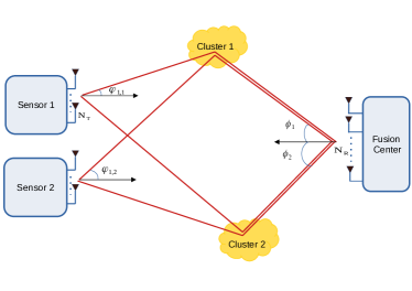
The mmWave MIMO channel 𝐆ksubscript𝐆𝑘{\mathbf{G}_{k}} between the FC and the k𝑘kth sensor is modelled using the spatial channel model of [36] having L𝐿L multipath components formulated as

𝐆ksubscript𝐆𝑘\displaystyle\mathbf{G}_{k} =NRNTLn=1Lαn,k𝐚R(ϕn)𝐚TH(φn,k),absentsubscript𝑁𝑅subscript𝑁𝑇𝐿superscriptsubscript𝑛1𝐿subscript𝛼𝑛𝑘subscript𝐚𝑅subscriptitalic-ϕ𝑛superscriptsubscript𝐚𝑇𝐻subscript𝜑𝑛𝑘\displaystyle=\sqrt{\frac{N_{R}N_{T}}{L}}\sum_{n=1}^{L}\alpha_{n,k}\boldsymbol{\mathrm{a}}_{R}(\phi_{n})\boldsymbol{\mathrm{a}}_{T}^{H}(\varphi_{n,k}), (12)

where the 3-tuple (αn,k,ϕn,φn,k)subscript𝛼𝑛𝑘subscriptitalic-ϕ𝑛subscript𝜑𝑛𝑘(\alpha_{n,k},\phi_{n},\varphi_{n,k}) denotes the complex gain αn,ksubscript𝛼𝑛𝑘\alpha_{n,k}, the angle of arrival (AoA) ϕnsubscriptitalic-ϕ𝑛\phi_{n} at the FC and angle of departure (AoD) φn,ksubscript𝜑𝑛𝑘\varphi_{n,k} at the k𝑘kth sensor associated with the n𝑛nth cluster. The spatial channel model of the mmWave MIMO WSN is presented in Fig. 2. Upon considering uniform linear arrays (ULAs) at the receiver and transmitters, the receive array response vector 𝐚R(ϕn)NR×1subscript𝐚𝑅subscriptitalic-ϕ𝑛superscriptsubscript𝑁𝑅1\boldsymbol{\mathrm{a}}_{R}(\phi_{n})\in\mathbb{C}^{N_{R}\times 1} and transmit array response vectors 𝐚T(φn,k)NT×1subscript𝐚𝑇subscript𝜑𝑛𝑘superscriptsubscript𝑁𝑇1\boldsymbol{\mathrm{a}}_{T}(\varphi_{n,k})\in\mathbb{C}^{N_{T}\times 1} are given by

𝐚R(ϕn)subscript𝐚𝑅subscriptitalic-ϕ𝑛\displaystyle\boldsymbol{\mathrm{a}}_{R}(\phi_{n}) =1NR[1,ejϕ~n,,ej(NR1)ϕ~n]T,absent1subscript𝑁𝑅superscript1superscript𝑒𝑗subscript~italic-ϕ𝑛superscript𝑒𝑗subscript𝑁𝑅1subscript~italic-ϕ𝑛𝑇\displaystyle=\frac{1}{\sqrt{N_{R}}}\left[1,e^{-j\widetilde{\phi}_{n}},...,e^{-j(N_{R}-1)\widetilde{\phi}_{n}}\right]^{T}, (13)
𝐚T(φn,k)subscript𝐚𝑇subscript𝜑𝑛𝑘\displaystyle\boldsymbol{\mathrm{a}}_{T}(\varphi_{n,k}) =1NT[1,ejφ~n,k,,ej(NT1)φ~n,k]T,absent1subscript𝑁𝑇superscript1superscript𝑒𝑗subscript~𝜑𝑛𝑘superscript𝑒𝑗subscript𝑁𝑇1subscript~𝜑𝑛𝑘𝑇\displaystyle=\frac{1}{\sqrt{N_{T}}}\left[1,e^{-j\widetilde{\varphi}_{n,k}},...,e^{-j(N_{T}-1)\widetilde{\varphi}_{n,k}}\right]^{T}, (14)

where ϕ~n=2πλdRcos(ϕn)subscript~italic-ϕ𝑛2𝜋𝜆subscript𝑑𝑅cossubscriptitalic-ϕ𝑛\widetilde{\phi}_{n}=\frac{2\pi}{\lambda}d_{R}\text{cos}(\phi_{n}) and φ~n,k=2πλdTcos(φn,k)subscript~𝜑𝑛𝑘2𝜋𝜆subscript𝑑𝑇cossubscript𝜑𝑛𝑘\widetilde{\varphi}_{n,k}=\frac{2\pi}{\lambda}d_{T}\text{cos}(\varphi_{n,k}). The quantities λ,dR𝜆subscript𝑑𝑅\lambda,d_{R} and dTsubscript𝑑𝑇d_{T} denote the carrier wavelength, and the inter-antenna spacings at the FC and each sensor, respectively. The mmWave MIMO channel 𝐆ksubscript𝐆𝑘\mathbf{G}_{k} can now be expressed in the compact form of:

𝐆k=𝐀R𝐃k𝐀T,kH,subscript𝐆𝑘subscript𝐀𝑅subscript𝐃𝑘superscriptsubscript𝐀𝑇𝑘𝐻\mathbf{G}_{k}=\mathbf{A}_{R}\mathbf{D}_{k}\mathbf{A}_{T,k}^{H}, (15)

where 𝐃k=NRNTLdiag(α1,k,α2,k,,αL,k)L×Lsubscript𝐃𝑘subscript𝑁𝑅subscript𝑁𝑇𝐿diagsubscript𝛼1𝑘subscript𝛼2𝑘subscript𝛼𝐿𝑘superscript𝐿𝐿\mathbf{D}_{k}=\sqrt{\frac{N_{R}N_{T}}{L}}\mathrm{diag}(\alpha_{1,k},\alpha_{2,k},...,\alpha_{L,k})\in\mathbb{C}^{L\times L} is a diagonal matrix containing the path gains of the channel on its principal diagonal. The quantities 𝐀T,kNT×Lsubscript𝐀𝑇𝑘superscriptsubscript𝑁𝑇𝐿\mathbf{A}_{T,k}\in\mathbb{C}^{N_{T}\times L}, 𝐀RNR×Lsubscript𝐀𝑅superscriptsubscript𝑁𝑅𝐿\mathbf{A}_{R}\in\mathbb{C}^{N_{R}\times L} denote the transmit and receive array response matrices, respectively, which are given by

𝐀T,k=[𝐚T(φ1,k),𝐚T(φ2,k),,𝐚T(φL,k)],subscript𝐀𝑇𝑘subscript𝐚𝑇subscript𝜑1𝑘subscript𝐚𝑇subscript𝜑2𝑘subscript𝐚𝑇subscript𝜑𝐿𝑘\displaystyle\mathbf{A}_{T,k}=\left[\boldsymbol{\mathrm{a}}_{T}(\varphi_{1,k}),\boldsymbol{\mathrm{a}}_{T}(\varphi_{2,k}),...,\boldsymbol{\mathrm{a}}_{T}(\varphi_{L,k})\right], (16)
𝐀R=[𝐚R(ϕ1),𝐚R(ϕ2),,𝐚R(ϕL)].subscript𝐀𝑅subscript𝐚𝑅subscriptitalic-ϕ1subscript𝐚𝑅subscriptitalic-ϕ2subscript𝐚𝑅subscriptitalic-ϕ𝐿\displaystyle\mathbf{A}_{R}=\left[\boldsymbol{\mathrm{a}}_{R}(\phi_{1}),\boldsymbol{\mathrm{a}}_{R}(\phi_{2}),...,\boldsymbol{\mathrm{a}}_{R}(\phi_{L})\right]. (17)

The concatenated mmWave channel can now be represented as

𝐆𝐆\displaystyle\mathbf{G} =[𝐆1,𝐆2,,𝐆K]absentsubscript𝐆1subscript𝐆2subscript𝐆𝐾\displaystyle=[\mathbf{G}_{1},\mathbf{G}_{2},\cdots,\mathbf{G}_{K}]
=𝐀R[𝐃1𝐀T,1H,𝐃2𝐀T,2H,,𝐃K𝐀T,KH]absentsubscript𝐀𝑅subscript𝐃1superscriptsubscript𝐀𝑇1𝐻subscript𝐃2superscriptsubscript𝐀𝑇2𝐻subscript𝐃𝐾superscriptsubscript𝐀𝑇𝐾𝐻\displaystyle=\mathbf{A}_{R}[\mathbf{D}_{1}\mathbf{A}_{T,1}^{H},\mathbf{D}_{2}\mathbf{A}_{T,2}^{H},\cdots,\mathbf{D}_{K}\mathbf{A}_{T,K}^{H}]
=𝐀R𝐃𝐀~TH,absentsubscript𝐀𝑅𝐃superscriptsubscript~𝐀𝑇𝐻\displaystyle=\mathbf{A}_{R}{\mathbf{D}}\widetilde{\mathbf{A}}_{T}^{H}, (18)

where 𝐃=[𝐃1,𝐃2,,𝐃K]L×KL𝐃subscript𝐃1subscript𝐃2subscript𝐃𝐾superscript𝐿𝐾𝐿{\mathbf{D}}=[\mathbf{D}_{1},\mathbf{D}_{2},\cdots,\mathbf{D}_{K}]\in\mathbb{C}^{L\times KL} and 𝐀~TH=blkdiag(𝐀T,1H,𝐀T,2H,,𝐀T,KH)KL×KNtsuperscriptsubscript~𝐀𝑇𝐻blkdiagsuperscriptsubscript𝐀𝑇1𝐻superscriptsubscript𝐀𝑇2𝐻superscriptsubscript𝐀𝑇𝐾𝐻superscript𝐾𝐿𝐾subscript𝑁𝑡\widetilde{\mathbf{A}}_{T}^{H}=\text{blkdiag}\left(\mathbf{A}_{T,1}^{H},\mathbf{A}_{T,2}^{H},\cdots,\mathbf{A}_{T,K}^{H}\right)\in\mathbb{C}^{KL\times KN_{t}}.

The optimization problem of the TPC sensor matrices 𝐅k=𝐅RF,k𝐅BB,kksubscript𝐅𝑘subscript𝐅RF𝑘subscript𝐅BB𝑘for-all𝑘\mathbf{F}_{k}=\mathbf{F}_{\text{RF},k}\mathbf{F}_{\text{BB},k}\ \forall k can now be formulated by minimizing the MSE under a given power constraint. The design procedures of various scenarios are described next.

III Hybrid MMSE Precoder/Combiner Design

In this section, our hybrid TPC is designed for both total power budget as well as per sensor power constraints and hybrid RC design of the FC.

III-A TPC design under total power budget

For the system having a total power budget across all the sensors, the fully-digital LMMSE RC 𝐖NR×m𝐖superscriptsubscript𝑁𝑅𝑚\mathbf{W}\in\mathbb{C}^{N_{R}\times m} used for estimating the underlying parameter 𝜽𝜽\boldsymbol{\theta} subject to noisy sensor observations is given by [37],

𝐖𝐖\displaystyle\mathbf{W} =(𝔼{𝐲𝐲H})1𝔼{𝐲𝜽H}absentsuperscript𝔼superscript𝐲𝐲𝐻1𝔼𝐲superscript𝜽𝐻\displaystyle=\left(\mathbb{E}\left\{\mathbf{y}\mathbf{y}^{H}\right\}\right)^{-1}\mathbb{E}\left\{\mathbf{y}\boldsymbol{\theta}^{H}\right\}
=(𝐆𝐅(𝐌𝐌H+𝐑n)𝐅H𝐆H+σv2𝐈NR)1𝐆𝐅𝐌absentsuperscript𝐆𝐅superscript𝐌𝐌𝐻subscript𝐑𝑛superscript𝐅𝐻superscript𝐆𝐻superscriptsubscript𝜎𝑣2subscript𝐈subscript𝑁𝑅1𝐆𝐅𝐌\displaystyle=\left({\mathbf{G}}\mathbf{F}\left(\mathbf{M}{\mathbf{M}}^{H}+\mathbf{R}_{n}\right)\mathbf{F}^{H}\mathbf{G}^{H}+\sigma_{v}^{2}\mathbf{I}_{N_{R}}\right)^{-1}\mathbf{G}\mathbf{F}{\mathbf{M}}
=𝐆𝐅((𝐌𝐌H+𝐑n)𝐅H𝐆H𝐆𝐅+σv2𝐈q)1𝐌,absent𝐆𝐅superscriptsuperscript𝐌𝐌𝐻subscript𝐑𝑛superscript𝐅𝐻superscript𝐆𝐻𝐆𝐅superscriptsubscript𝜎𝑣2subscript𝐈𝑞1𝐌\displaystyle=\mathbf{G}\mathbf{F}\left(\left(\mathbf{M}{\mathbf{M}}^{H}+\mathbf{R}_{n}\right)\mathbf{F}^{H}\mathbf{G}^{H}{\mathbf{G}}\mathbf{F}+\sigma_{v}^{2}\mathbf{I}_{q}\right)^{-1}{\mathbf{M}}, (19)

where the last step follows using the matrix identity (𝐈+𝐔𝐀𝐕)1𝐔=𝐔(𝐈+𝐀𝐕𝐔)1superscript𝐈𝐔𝐀𝐕1𝐔𝐔superscript𝐈𝐀𝐕𝐔1\left(\mathbf{I}+\mathbf{UAV}\right)^{-1}\mathbf{U}=\mathbf{U}\left(\mathbf{I}+\mathbf{AVU}\right)^{-1}. The resultant error covariance matrix is shown in (20).

𝐄=(𝐈m+𝐌H𝐅H𝐆H(𝐆𝐅𝐑n𝐅H𝐆H+σv2𝐈NR)1𝐆𝐅𝐌)1.𝐄superscriptsubscript𝐈𝑚superscript𝐌𝐻superscript𝐅𝐻superscript𝐆𝐻superscriptsubscript𝐆𝐅𝐑𝑛superscript𝐅𝐻superscript𝐆𝐻superscriptsubscript𝜎𝑣2subscript𝐈subscript𝑁𝑅1𝐆𝐅𝐌1\mathbf{E}=\left(\mathbf{I}_{m}+\mathbf{M}^{H}\mathbf{F}^{H}\mathbf{G}^{H}\left(\mathbf{G}\mathbf{F}\mathbf{R}_{n}\mathbf{F}^{H}\mathbf{G}^{H}+\sigma_{v}^{2}\mathbf{I}_{N_{R}}\right)^{-1}\mathbf{G}\mathbf{F}\mathbf{M}\right)^{-1}. (20)
𝐄𝐄\displaystyle\mathbf{E} =(𝐈m+𝐌H𝐑n1𝐌𝐌H𝐑n1(1σv2𝐅H𝐆H𝐆𝐅+𝐑n1)1𝐑n1𝐌)1absentsuperscriptsubscript𝐈𝑚superscript𝐌𝐻superscriptsubscript𝐑𝑛1𝐌superscript𝐌𝐻superscriptsubscript𝐑𝑛1superscript1superscriptsubscript𝜎𝑣2superscript𝐅𝐻superscript𝐆𝐻𝐆𝐅superscriptsubscript𝐑𝑛11superscriptsubscript𝐑𝑛1𝐌1\displaystyle=\left(\mathbf{I}_{m}+\mathbf{M}^{H}\mathbf{R}_{n}^{-1}\mathbf{M}-\mathbf{M}^{H}\mathbf{R}_{n}^{-1}\left(\frac{1}{\sigma_{v}^{2}}\mathbf{F}^{H}\mathbf{G}^{H}\mathbf{G}\mathbf{F}+\mathbf{R}_{n}^{-1}\right)^{-1}\mathbf{R}_{n}^{-1}\mathbf{M}\right)^{-1}
=(𝐈m+1σn2𝐌H𝐌1σn2𝐌H(σn2σv2𝐅H𝐆H𝐆𝐅+𝐈q)1𝐌)1.absentsuperscriptsubscript𝐈𝑚1superscriptsubscript𝜎𝑛2superscript𝐌𝐻𝐌1superscriptsubscript𝜎𝑛2superscript𝐌𝐻superscriptsuperscriptsubscript𝜎𝑛2superscriptsubscript𝜎𝑣2superscript𝐅𝐻superscript𝐆𝐻𝐆𝐅subscript𝐈𝑞1𝐌1\displaystyle=\left(\mathbf{I}_{m}+\frac{1}{\sigma_{n}^{2}}\mathbf{M}^{H}\mathbf{M}-\frac{1}{\sigma_{n}^{2}}\mathbf{M}^{H}\left(\frac{\sigma_{n}^{2}}{\sigma_{v}^{2}}\mathbf{F}^{H}\mathbf{G}^{H}\mathbf{G}\mathbf{F}+\mathbf{I}_{q}\right)^{-1}\mathbf{M}\right)^{-1}. (21)

Employing the Woodbury matrix identity [38] for simplifying the term (𝐆𝐅𝐑n𝐅H𝐆H+σv2𝐈NR)1superscriptsubscript𝐆𝐅𝐑𝑛superscript𝐅𝐻superscript𝐆𝐻superscriptsubscript𝜎𝑣2subscript𝐈subscript𝑁𝑅1\left(\mathbf{G}\mathbf{F}\mathbf{R}_{n}\mathbf{F}^{H}\mathbf{G}^{H}+\sigma_{v}^{2}\mathbf{I}_{N_{R}}\right)^{-1} and considering the noise covariance matrix 𝐑n=σn2𝐈qsubscript𝐑𝑛superscriptsubscript𝜎𝑛2subscript𝐈𝑞\mathbf{R}_{n}=\sigma_{n}^{2}\mathbf{I}_{q}, the error covariance matrix can be formulated as shown in (21). Our hybrid TPC design based on MSE minimization can be formulated as

minimize{𝐅RF,k,𝐅BB,k}k=1KTr(𝐄)subscriptminimizesuperscriptsubscriptsubscript𝐅RF𝑘subscript𝐅BB𝑘𝑘1𝐾Tr𝐄\displaystyle\mathop{\text{minimize}}_{\left\{\mathbf{F}_{\text{RF},k},\mathbf{F}_{\text{BB},k}\right\}_{k=1}^{K}}\ \text{Tr}\left(\mathbf{E}\right)
subject toTr(𝐅RF𝐅BB(𝐌𝐌H+σn2𝐈q)𝐅BBH𝐅RFH)PT,subject toTrsubscript𝐅RFsubscript𝐅BBsuperscript𝐌𝐌𝐻superscriptsubscript𝜎𝑛2subscript𝐈𝑞superscriptsubscript𝐅BB𝐻superscriptsubscript𝐅RF𝐻subscript𝑃𝑇\displaystyle\quad\ \text{subject to}\quad\ \textrm{Tr}\left(\mathbf{F}_{\text{RF}}\mathbf{F}_{\text{BB}}\left(\mathbf{M}\mathbf{M}^{H}+\sigma_{n}^{2}\mathbf{I}_{q}\right){\mathbf{F}_{\text{BB}}}^{H}{\mathbf{F}_{\text{RF}}}^{H}\right)\leq{P}_{T},
|𝐅RF,k(s,t)|=1NT, 1kK,formulae-sequencesubscript𝐅RF𝑘𝑠𝑡1subscript𝑁𝑇1𝑘𝐾\displaystyle\quad\quad\quad\quad\quad\quad\ \ |\mathbf{F}_{\text{RF},k}(s,t)|=\frac{1}{\sqrt{N_{T}}},\ 1\leq k\leq K,

where PTsubscript𝑃𝑇P_{T} denotes the WSN’s total transmit power budget. The aforementioned problem is non-convex and intractable owing to the constant modulus constraint of the RF TPC 𝐅RF,ksubscript𝐅RF𝑘\mathbf{F}_{\text{RF},k}. To circumvent this, we first design the optimal fully-digital hybrid TPC given by 𝐅=𝐅RF𝐅BB𝐅subscript𝐅RFsubscript𝐅BB\mathbf{F}=\mathbf{F}_{\text{RF}}\mathbf{F}_{\text{BB}}. The resultant hybrid TPC is then decomposed into its baseband and RF components. The convex optimization problem of the fully-digital TPC 𝐅𝐅\mathbf{F} is thus formulated as follows

minimize𝐅𝐅minimize\displaystyle\underset{\mathbf{{F}}}{\text{minimize}} Tr(𝐄)Tr𝐄\displaystyle\text{Tr}\left(\mathbf{E}\right) (22)
subject to Tr(𝐅(𝐌𝐌H+σn2𝐈l)𝐅H)PT.Tr𝐅superscript𝐌𝐌𝐻superscriptsubscript𝜎𝑛2subscript𝐈𝑙superscript𝐅𝐻subscript𝑃𝑇\displaystyle\text{Tr}\left(\mathbf{F}\left(\mathbf{M}\mathbf{M}^{H}+\sigma_{n}^{2}\mathbf{I}_{l}\right){\mathbf{F}}^{H}\right)\leq{P}_{T}.
𝐄𝐄\displaystyle\mathbf{E} =(𝐕M𝐕MH+1σn2𝐕M(𝚲M𝚺MH𝐔MH(σn2σv2𝐅H𝐕g𝚲g𝐕gH𝐅+𝐈q)1𝐔M𝚺M)𝐕MH)1absentsuperscriptsubscript𝐕𝑀superscriptsubscript𝐕𝑀𝐻1superscriptsubscript𝜎𝑛2subscript𝐕𝑀subscript𝚲𝑀superscriptsubscript𝚺𝑀𝐻superscriptsubscript𝐔𝑀𝐻superscriptsuperscriptsubscript𝜎𝑛2superscriptsubscript𝜎𝑣2superscript𝐅𝐻subscript𝐕𝑔subscript𝚲𝑔superscriptsubscript𝐕𝑔𝐻𝐅subscript𝐈𝑞1subscript𝐔𝑀subscript𝚺𝑀superscriptsubscript𝐕𝑀𝐻1\displaystyle=\left(\mathbf{V}_{M}\mathbf{V}_{M}^{H}+\frac{1}{\sigma_{n}^{2}}\mathbf{V}_{M}\left(\boldsymbol{\Lambda}_{M}-\mathbf{\Sigma}_{M}^{H}\mathbf{U}_{M}^{H}\left(\frac{\sigma_{n}^{2}}{\sigma_{v}^{2}}\mathbf{F}^{H}\mathbf{V}_{g}\mathbf{\Lambda}_{g}\mathbf{V}_{g}^{H}\mathbf{F}+\mathbf{I}_{q}\right)^{-1}\mathbf{U}_{M}\mathbf{\Sigma}_{M}\right)\mathbf{V}_{M}^{H}\right)^{-1}
=(𝐈m+1σn2(𝚲M𝚺MH𝐔MH(σn2σv2𝐅H𝐕g𝚲g𝐕gH𝐅+𝐈q)1𝐔M𝚺M))1absentsuperscriptsubscript𝐈𝑚1superscriptsubscript𝜎𝑛2subscript𝚲𝑀superscriptsubscript𝚺𝑀𝐻superscriptsubscript𝐔𝑀𝐻superscriptsuperscriptsubscript𝜎𝑛2superscriptsubscript𝜎𝑣2superscript𝐅𝐻subscript𝐕𝑔subscript𝚲𝑔superscriptsubscript𝐕𝑔𝐻𝐅subscript𝐈𝑞1subscript𝐔𝑀subscript𝚺𝑀1\displaystyle=\left(\mathbf{I}_{m}+\frac{1}{\sigma_{n}^{2}}\left(\boldsymbol{\Lambda}_{M}-\mathbf{\Sigma}_{M}^{H}\mathbf{U}_{M}^{H}\left(\frac{\sigma_{n}^{2}}{\sigma_{v}^{2}}\mathbf{F}^{H}\mathbf{V}_{g}\mathbf{\Lambda}_{g}\mathbf{V}_{g}^{H}\mathbf{F}+\mathbf{I}_{q}\right)^{-1}\mathbf{U}_{M}\mathbf{\Sigma}_{M}\right)\right)^{-1}
=(𝐈m+1σn2𝚺MH(𝑰q(σn2σv2𝐔MH𝐅H𝐕g𝚲g𝐕gH𝐅𝐔M+𝐔MH𝐔M)1)𝚺M)1.absentsuperscriptsubscript𝐈𝑚1superscriptsubscript𝜎𝑛2superscriptsubscript𝚺𝑀𝐻subscript𝑰𝑞superscriptsuperscriptsubscript𝜎𝑛2superscriptsubscript𝜎𝑣2superscriptsubscript𝐔𝑀𝐻superscript𝐅𝐻subscript𝐕𝑔subscript𝚲𝑔superscriptsubscript𝐕𝑔𝐻subscript𝐅𝐔𝑀superscriptsubscript𝐔𝑀𝐻subscript𝐔𝑀1subscript𝚺𝑀1\displaystyle=\left(\mathbf{I}_{m}+\frac{1}{\sigma_{n}^{2}}\mathbf{\Sigma}_{M}^{H}\left(\boldsymbol{I}_{q}-\left(\frac{\sigma_{n}^{2}}{\sigma_{v}^{2}}\mathbf{U}_{M}^{H}\mathbf{F}^{H}\mathbf{V}_{g}\mathbf{\Lambda}_{g}\mathbf{V}_{g}^{H}\mathbf{F}\mathbf{U}_{M}+\mathbf{U}_{M}^{H}\mathbf{U}_{M}\right)^{-1}\right)\mathbf{\Sigma}_{M}\right)^{-1}. (23)

The above matrix-based optimization problem in terms of 𝐅𝐅\mathbf{F} can be converted to an equivalent scalar valued convex optimization problem via majorization theory [39]. Since the trace of the error covariance matrix 𝐄𝐄\mathbf{E} is a Schur-concave function [40], the MSE cost function value achieves the lower bound when diag(𝐄~)=𝝀(𝐄~)diag~𝐄𝝀~𝐄\mathrm{diag}\left(\mathbf{\widetilde{E}}\right)=\mathbf{\boldsymbol{\lambda}\left(\widetilde{E}\right)}, and the optimal solution is obtained when the matrix is diagonalized. Let the singular value decomposition (SVD) of 𝐌𝐌\mathbf{{M}} be given by 𝐔M𝚺M𝐕MHsubscript𝐔𝑀subscript𝚺𝑀superscriptsubscript𝐕𝑀𝐻\mathbf{U}_{{M}}\mathbf{\Sigma}_{{M}}\mathbf{V}_{M}^{H}. Also, the eigenvalue decomposition (EVD) of 𝐌~=𝐌H𝐌~𝐌superscript𝐌𝐻𝐌\widetilde{\mathbf{M}}=\mathbf{{M}}^{H}\mathbf{{M}} be denoted as 𝐕M~𝚲M~𝐕M~Hsubscript𝐕~𝑀subscript𝚲~𝑀superscriptsubscript𝐕~𝑀𝐻\mathbf{V}_{\widetilde{M}}\mathbf{\Lambda}_{\widetilde{M}}\mathbf{V}_{\widetilde{M}}^{H}, where 𝚲M~m×msubscript𝚲~𝑀superscript𝑚𝑚\mathbf{\Lambda}_{\widetilde{M}}\in\mathbb{C}^{m\times m} is given by 𝚲M~=diag[λ1(𝐌~),λ2(𝐌~),λm(𝐌~)].subscript𝚲~𝑀diagsubscript𝜆1~𝐌subscript𝜆2~𝐌subscript𝜆𝑚~𝐌\mathbf{\Lambda}_{\widetilde{M}}=\mathrm{diag}\left[\lambda_{1}(\widetilde{\mathbf{M}}),\lambda_{2}(\widetilde{\mathbf{M}}),\cdots\lambda_{m}(\widetilde{\mathbf{M}})\right]. Let the SVD of the concatenated mmWave MIMO channel 𝐆NR×KNT𝐆superscriptsubscript𝑁𝑅𝐾subscript𝑁𝑇\mathbf{G}\in\mathbb{C}^{N_{R}\times KN_{T}} be given as 𝐆=𝐔g𝚺g𝐕gH.𝐆subscript𝐔𝑔subscript𝚺𝑔superscriptsubscript𝐕𝑔𝐻\mathbf{{G}}=\mathbf{U}_{g}\mathbf{\Sigma}_{g}\mathbf{V}_{g}^{H}. Furthermore, the EVD of 𝐆H𝐆superscript𝐆𝐻𝐆\mathbf{G}^{H}\mathbf{G} may be derived as 𝐆~=𝐆H𝐆=𝐕g𝚲g𝐕gH~𝐆superscript𝐆𝐻𝐆subscript𝐕𝑔subscript𝚲𝑔superscriptsubscript𝐕𝑔𝐻\widetilde{\mathbf{G}}=\mathbf{G}^{H}\mathbf{G}=\mathbf{V}_{g}\mathbf{\Lambda}_{g}\mathbf{V}_{g}^{H}, where 𝚲gKNT×KNTsubscript𝚲𝑔superscript𝐾subscript𝑁𝑇𝐾subscript𝑁𝑇\mathbf{\Lambda}_{g}\in\mathbb{C}^{KN_{T}\times KN_{T}} is given by 𝚲g=𝚺gH𝚺g=diag[σ12(𝐆),σ22(𝐆),,σKNT2(𝐆)],subscript𝚲𝑔subscriptsuperscript𝚺𝐻𝑔subscript𝚺𝑔diagsubscriptsuperscript𝜎21𝐆subscriptsuperscript𝜎22𝐆subscriptsuperscript𝜎2𝐾subscript𝑁𝑇𝐆\mathbf{\Lambda}_{g}=\mathbf{\Sigma}^{H}_{g}\mathbf{\Sigma}_{g}=\mathrm{diag}\left[\sigma^{2}_{1}\left({\mathbf{{G}}}\right),\sigma^{2}_{2}\left({\mathbf{{G}}}\right),\cdots,\sigma^{2}_{KN_{T}}\left({\mathbf{{G}}}\right)\right], with the first L𝐿L non-zero eigenvalues arranged in decreasing order and σl(𝐆)subscript𝜎𝑙𝐆\sigma_{l}\left(\mathbf{G}\right) denotes the l𝑙lth singular value. The above decompositions can be substituted into the expression of the error covariance matrix 𝐄𝐄\mathbf{E} in (21), which allows the final expression to be simplified to the one shown in (III-A). From Appendix A, in order to diagonalize (III-A), one can choose the following structure

𝐅𝐔M=𝐕g1𝚺,subscript𝐅𝐔𝑀subscriptsuperscript𝐕1𝑔𝚺\mathbf{F}\mathbf{U}_{M}=\mathbf{V}^{1}_{g}\mathbf{\Sigma}, (24)

where we have a diagonal matrix 𝚺m×m𝚺superscript𝑚𝑚\mathbf{\Sigma}\in\mathbb{R}^{m\times m} and 𝐕g1subscriptsuperscript𝐕1𝑔\mathbf{V}^{1}_{g} is comprised of the m𝑚m dominant left singular vectors of 𝐕gsubscript𝐕𝑔\mathbf{V}_{g}. The error covariance matrix from (III-A) is now diagonalized by substituting (24) into (III-A), and the MSE is given in (III-A), where we have:

𝐕gH𝐕g1=[𝐈m𝟎(KNTm)×q],𝚲~g=𝚲g(1:m,1:m).\displaystyle\mathbf{V}_{g}^{H}\mathbf{V}^{1}_{g}=\begin{bmatrix}\mathbf{I}_{m}\\ \mathbf{0}_{(KN_{T}-m)\times q}\end{bmatrix},\mathbf{\widetilde{\Lambda}}_{g}=\mathbf{{\Lambda}}_{g}\left(1:m,1:m\right).
MSE =Tr((𝐈m+1σn2𝚺MH(𝑰q(σn2σv2𝚺H𝐕g1H𝐕g𝚲g𝐕gH𝐕g1𝚺+𝐈q)1)𝚺M)1)absentTrsuperscriptsubscript𝐈𝑚1superscriptsubscript𝜎𝑛2superscriptsubscript𝚺𝑀𝐻subscript𝑰𝑞superscriptsuperscriptsubscript𝜎𝑛2superscriptsubscript𝜎𝑣2superscript𝚺𝐻superscriptsubscriptsuperscript𝐕1𝑔𝐻subscript𝐕𝑔subscript𝚲𝑔superscriptsubscript𝐕𝑔𝐻subscriptsuperscript𝐕1𝑔𝚺subscript𝐈𝑞1subscript𝚺𝑀1\displaystyle=\text{Tr}\left(\left(\mathbf{I}_{m}+\frac{1}{\sigma_{n}^{2}}\mathbf{\Sigma}_{M}^{H}\left(\boldsymbol{I}_{q}-\left(\frac{\sigma_{n}^{2}}{\sigma_{v}^{2}}\mathbf{\Sigma}^{H}{\mathbf{V}^{1}_{g}}^{H}\mathbf{V}_{g}\mathbf{\Lambda}_{g}\mathbf{V}_{g}^{H}\mathbf{V}^{1}_{g}\mathbf{\Sigma}+\mathbf{I}_{q}\right)^{-1}\right)\mathbf{\Sigma}_{M}\right)^{-1}\right)
=Tr((𝐈m+1σn2𝚺MH(𝑰q(σn2σv2𝚺H𝚲~g𝚺+𝐈q)1)𝚺M)1)absentTrsuperscriptsubscript𝐈𝑚1superscriptsubscript𝜎𝑛2superscriptsubscript𝚺𝑀𝐻subscript𝑰𝑞superscriptsuperscriptsubscript𝜎𝑛2superscriptsubscript𝜎𝑣2superscript𝚺𝐻subscript~𝚲𝑔𝚺subscript𝐈𝑞1subscript𝚺𝑀1\displaystyle=\text{Tr}\left(\left(\mathbf{I}_{m}+\frac{1}{\sigma_{n}^{2}}\mathbf{\Sigma}_{M}^{H}\left(\boldsymbol{I}_{q}-\left(\frac{\sigma_{n}^{2}}{\sigma_{v}^{2}}\mathbf{\Sigma}^{H}\mathbf{\widetilde{\Lambda}}_{g}\mathbf{\Sigma}+\mathbf{I}_{q}\right)^{-1}\right)\mathbf{\Sigma}_{M}\right)^{-1}\right)
=Tr((𝐈m+1σn2𝚺~MH(𝑰m(σn2σv2𝚺~H𝚲~g𝚺~+𝐈m)1)𝚺~M)1).absentTrsuperscriptsubscript𝐈𝑚1superscriptsubscript𝜎𝑛2superscriptsubscript~𝚺𝑀𝐻subscript𝑰𝑚superscriptsuperscriptsubscript𝜎𝑛2superscriptsubscript𝜎𝑣2superscript~𝚺𝐻subscript~𝚲𝑔~𝚺subscript𝐈𝑚1subscript~𝚺𝑀1\displaystyle=\text{Tr}\left(\left(\mathbf{I}_{m}+\frac{1}{\sigma_{n}^{2}}\mathbf{\widetilde{\Sigma}}_{M}^{H}\left(\boldsymbol{I}_{m}-\left(\frac{\sigma_{n}^{2}}{\sigma_{v}^{2}}\mathbf{\widetilde{\Sigma}}^{H}\mathbf{\widetilde{\Lambda}}_{g}\mathbf{\widetilde{\Sigma}}+\mathbf{I}_{m}\right)^{-1}\right)\mathbf{\widetilde{\Sigma}}_{M}\right)^{-1}\right). (25)

The matrix 𝚺m×m𝚺superscript𝑚𝑚\mathbf{\Sigma}\in\mathbb{R}^{m\times m} is given as 𝚺=[diag(𝐩)]m×m12𝚺subscriptsuperscriptdelimited-[]diag𝐩12𝑚𝑚\mathbf{\Sigma}=\left[\mathrm{diag}\left(\boldsymbol{\mathrm{p}}\right)\right]^{\frac{1}{2}}_{m\times m} where 𝐩=[p1,p2,,pm]T𝐩superscriptsubscript𝑝1subscript𝑝2subscript𝑝𝑚𝑇{\mathbf{p}}=\left[{p_{1}},{p_{2}},...,{p}_{m}\right]^{T} is the power allocation vector. Thus, the MSE can now be written as

MSE=l=1mσv2+σn2plσl2(𝐆~)σv2+(σn2+λl(𝐌~))plσl2(𝐆~).MSEsuperscriptsubscript𝑙1𝑚superscriptsubscript𝜎𝑣2superscriptsubscript𝜎𝑛2subscript𝑝𝑙subscriptsuperscript𝜎2𝑙~𝐆superscriptsubscript𝜎𝑣2superscriptsubscript𝜎𝑛2subscript𝜆𝑙~𝐌subscript𝑝𝑙subscriptsuperscript𝜎2𝑙~𝐆\text{MSE}=\sum_{l=1}^{m}\frac{\sigma_{v}^{2}+\sigma_{n}^{2}p_{l}\sigma^{2}_{l}(\widetilde{\mathbf{G}})}{\sigma_{v}^{2}+\left(\sigma_{n}^{2}+\lambda_{l}(\widetilde{\mathbf{M}})\right)p_{l}\sigma^{2}_{l}(\widetilde{\mathbf{G}})}. (26)

Substituting the TPC matrix 𝐅𝐅\mathbf{F} and using EVD of 𝐌~~𝐌\widetilde{\mathbf{M}}, the total transmit power can be expressed as

Tr(𝐅(𝐌𝐌H+σn2𝐈q)𝐅H)Tr𝐅superscript𝐌𝐌𝐻superscriptsubscript𝜎𝑛2subscript𝐈𝑞superscript𝐅𝐻\displaystyle\text{Tr}\left(\mathbf{F}\left(\mathbf{M}\mathbf{M}^{H}+\sigma_{n}^{2}\mathbf{I}_{q}\right){\mathbf{F}}^{H}\right)
=Tr(𝐕g1𝚺(𝚲M~H+σn2𝐈q)𝚺H(𝐕g1)H)absentTrsubscriptsuperscript𝐕1𝑔𝚺superscriptsubscript𝚲~𝑀𝐻superscriptsubscript𝜎𝑛2subscript𝐈𝑞superscript𝚺𝐻superscriptsubscriptsuperscript𝐕1𝑔𝐻\displaystyle=\text{Tr}\left(\mathbf{V}^{1}_{g}\mathbf{\Sigma}\left(\mathbf{\Lambda}_{\widetilde{M}}^{H}+\sigma_{n}^{2}\mathbf{I}_{q}\right)\mathbf{\Sigma}^{H}(\mathbf{V}^{1}_{g})^{H}\right)
=l=1mpl(λl(𝐌~)+σn2).absentsuperscriptsubscript𝑙1𝑚subscript𝑝𝑙subscript𝜆𝑙~𝐌superscriptsubscript𝜎𝑛2\displaystyle=\sum_{l=1}^{m}p_{l}\left(\lambda_{l}(\widetilde{\mathbf{M}})+\sigma_{n}^{2}\right). (27)

Using (26) and (III-A), the optimization problem of minimizing the MSE of the estimate of the parameter vector 𝜽𝜽\boldsymbol{\theta} subject to a power constraint can be equivalently formulated as

minimize𝐩𝐩minimize\displaystyle\underset{\mathbf{p}}{\text{minimize}}\ l=1mσv2+σn2plσl2(𝐆~)σv2+(σn2+λl(𝐌~))plσl2(𝐆~)superscriptsubscript𝑙1𝑚superscriptsubscript𝜎𝑣2superscriptsubscript𝜎𝑛2subscript𝑝𝑙subscriptsuperscript𝜎2𝑙~𝐆superscriptsubscript𝜎𝑣2superscriptsubscript𝜎𝑛2subscript𝜆𝑙~𝐌subscript𝑝𝑙subscriptsuperscript𝜎2𝑙~𝐆\displaystyle\sum_{l=1}^{m}\frac{\sigma_{v}^{2}+\sigma_{n}^{2}p_{l}\sigma^{2}_{l}(\widetilde{\mathbf{G}})}{\sigma_{v}^{2}+\left(\sigma_{n}^{2}+\lambda_{l}(\widetilde{\mathbf{M}})\right)p_{l}\sigma^{2}_{l}(\widetilde{\mathbf{G}})}
subject to l=1mpl(λl(𝐌~)+σn2)PT,superscriptsubscript𝑙1𝑚subscript𝑝𝑙subscript𝜆𝑙~𝐌superscriptsubscript𝜎𝑛2subscript𝑃𝑇\displaystyle\sum\limits_{l=1}^{m}p_{l}\left(\lambda_{l}(\widetilde{\mathbf{M}})+\sigma_{n}^{2}\right)\leq P_{T},
pl0,1lm.formulae-sequencesubscript𝑝𝑙01𝑙𝑚\displaystyle p_{l}\geq 0,1\leq l\leq m. (28)

The above problem is convex in terms of the power allocation vector 𝐩𝐩\mathbf{p}. Employing the Karush-Kuhn-Tucker (KKT) conditions [41], the optimal value of plsubscript𝑝𝑙p_{l} is obtained as

pl=(μσv2λl(𝐌~)σl2(𝐆~)(σn2+λl(𝐌~))σv2)+(σn2+λl(𝐌~))σl2(𝐆~),subscript𝑝𝑙superscript𝜇superscriptsubscript𝜎𝑣2subscript𝜆𝑙~𝐌subscriptsuperscript𝜎2𝑙~𝐆superscriptsubscript𝜎𝑛2subscript𝜆𝑙~𝐌superscriptsubscript𝜎𝑣2superscriptsubscript𝜎𝑛2subscript𝜆𝑙~𝐌subscriptsuperscript𝜎2𝑙~𝐆p_{l}=\frac{\left(\mu\sqrt{\frac{\sigma_{v}^{2}\lambda_{l}(\widetilde{\mathbf{M}})\sigma^{2}_{l}(\widetilde{\mathbf{G}})}{\left(\sigma_{n}^{2}+\lambda_{l}(\widetilde{\mathbf{M}})\right)}}-\sigma_{v}^{2}\right)^{+}}{\left(\sigma_{n}^{2}+\lambda_{l}(\widetilde{\mathbf{M}})\right)\sigma^{2}_{l}(\widetilde{\mathbf{G}})}, (29)

where the Lagrangian multiplier μ𝜇\mu is given by

μ=PT+l=1mσv2σl2(𝐆~)l=1mσv2λl(𝐌~)(σn2+λl(𝐌~))σl2(𝐆~).𝜇subscript𝑃𝑇superscriptsubscript𝑙1𝑚superscriptsubscript𝜎𝑣2subscriptsuperscript𝜎2𝑙~𝐆superscriptsubscript𝑙1𝑚superscriptsubscript𝜎𝑣2subscript𝜆𝑙~𝐌superscriptsubscript𝜎𝑛2subscript𝜆𝑙~𝐌subscriptsuperscript𝜎2𝑙~𝐆\mu=\frac{P_{T}+\sum_{l=1}^{m}\frac{\sigma_{v}^{2}}{\sigma^{2}_{l}(\widetilde{\mathbf{G}})}}{\sum_{l=1}^{m}\sqrt{\frac{\sigma_{v}^{2}\lambda_{l}(\widetilde{\mathbf{M}})}{\left(\sigma_{n}^{2}+\lambda_{l}(\widetilde{\mathbf{M}})\right)\sigma^{2}_{l}(\widetilde{\mathbf{G}})}}}. (30)

The matrix 𝐅𝐔Msubscript𝐅𝐔𝑀\mathbf{{F}}\mathbf{U}_{M} is obtained by substituting the optimal values plsubscript𝑝𝑙p_{l} into the expression of 𝚺𝚺\mathbf{\Sigma} in (24). The individual fully-digital TPCs 𝐅ksubscript𝐅𝑘\mathbf{F}_{k}, 1kK1𝑘𝐾1\leq k\leq K, can be determined as

𝐅k=𝐕g,k1𝚺(𝐔M,k),subscript𝐅𝑘superscriptsubscript𝐕𝑔𝑘1𝚺superscriptsubscript𝐔𝑀𝑘\mathbf{F}_{k}=\mathbf{V}_{g,k}^{1}\boldsymbol{\Sigma}\left(\mathbf{U}_{M,k}\right)^{\dagger}, (31)

where 𝐕g,k1subscriptsuperscript𝐕1𝑔𝑘\mathbf{V}^{1}_{g,k} denotes the sub-matrix of 𝐕g1subscriptsuperscript𝐕1𝑔\mathbf{V}^{1}_{g} comprised of the rows from (k1)NT+1𝑘1subscript𝑁𝑇1(k-1)N_{T}+1 to kNT𝑘subscript𝑁𝑇kN_{T}, whereas 𝐔M,ksubscript𝐔𝑀𝑘\mathbf{U}_{M,k} is the sub-matrix of 𝐔Msubscript𝐔𝑀\mathbf{U}_{M} comprising the rows from j=1k1qj+1superscriptsubscript𝑗1𝑘1subscript𝑞𝑗1\sum_{j=1}^{k-1}q_{j}+1 to j=1kqjsuperscriptsubscript𝑗1𝑘subscript𝑞𝑗\sum_{j=1}^{k}q_{j}.

The RF TPC 𝐅RF,ksubscript𝐅RF𝑘\mathbf{F}_{\text{RF},k} and baseband TPC 𝐅BB,ksubscript𝐅BB𝑘\mathbf{F}_{\text{BB},k} can now be designed from the optimal fully-digital precoder 𝐅ksubscript𝐅𝑘\mathbf{F}_{k} of the k𝑘kth sensor as follows

minimize𝐅RF,k,𝐅BB,ksubscript𝐅RF𝑘subscript𝐅BB𝑘minimize\displaystyle\underset{\mathbf{F}_{\text{RF},k},{\mathbf{F}_{\text{BB},k}}}{\text{minimize}} (𝐅k𝐅RF,k𝐅BB,k)F2superscriptsubscriptnormsubscript𝐅𝑘subscript𝐅RF𝑘subscript𝐅BB𝑘𝐹2\displaystyle\left\|{\left(\mathbf{F}_{k}-\mathbf{F}_{\text{RF},k}{\mathbf{F}}_{\text{BB},k}\right)}\right\|_{F}^{2} (32)
subject to |𝐅RF,k(s,t)|=1NT,subscript𝐅RF𝑘𝑠𝑡1subscript𝑁𝑇\displaystyle|\mathbf{F}_{\text{RF},k}(s,t)|=\frac{1}{\sqrt{N_{T}}},

where 𝐙Fsubscriptnorm𝐙𝐹\left\|\mathbf{Z}\right\|_{F} denotes the Frobenius norm [20] of the matrix 𝐙𝐙\mathbf{Z}. Due to the constant magnitude problem described earlier, the problem is non-convex and intractable. However, we can now implement the ensuing remarks which allows us to simplify the hybrid TPC design. Please note that our system model is different from that of cellular mmWave MIMO systems that employ either point-to-point MIMO or multi-user MIMO communication systems. In our work, we consider a coherent MAC channel where the signals gleaned from the sensor nodes are superimposed at the FC. Therefore, the detailed proofs that demonstrate the fact that the fully-digital TPC lies in the row space of the corresponding MIMO channel is also an important novel contribution of this work. From (15), it can be inferred that the row and column spaces of the mmWave MIMO channel 𝐆ksubscript𝐆𝑘\mathbf{G}_{k} between the k𝑘kth sensor and FC constitute a subset of the column spaces of the transmit and receive array response matrices 𝐀T,ksubscript𝐀𝑇𝑘\mathbf{A}_{T,k} and 𝐀Rsubscript𝐀𝑅\mathbf{A}_{R}, respectively, i.e.

(𝐆k)𝒞(𝐀T,k)and𝒞(𝐆k)𝒞(𝐀R).formulae-sequencesubscript𝐆𝑘𝒞subscript𝐀𝑇𝑘and𝒞subscript𝐆𝑘𝒞subscript𝐀𝑅\mathcal{R}\left(\mathbf{G}_{k}\right)\subseteq\mathcal{C}\left(\mathbf{A}_{T,k}\right)\ \ \text{and}\ \ \mathcal{C}\left(\mathbf{G}_{k}\right)\subseteq\mathcal{C}\left(\mathbf{A}_{R}\right). (33)

Furthermore, interestingly, the relationship between the column-space of the fully-digital TPC 𝐅ksubscript𝐅𝑘\mathbf{F}_{k} at the k𝑘kth sensor and the column-space of the transmit array response matrix 𝐀T,ksubscript𝐀𝑇𝑘\mathbf{A}_{T,k} is presented in the theorem below.

Theorem 1.

The column-space of the optimal fully-digital TPC 𝐅ksubscript𝐅𝑘\mathbf{F}_{k} at the k𝑘kth sensor lies in the column-space of the transmit array response matrix 𝒞(𝐀T,k)𝒞subscript𝐀𝑇𝑘\mathcal{C}\left(\mathbf{A}_{T,k}\right), i.e.,

𝒞(𝐅k)𝒞(𝐀T,k).𝒞subscript𝐅𝑘𝒞subscript𝐀𝑇𝑘\mathcal{C}\left(\mathbf{F}_{k}\right)\subseteq\mathcal{C}\left(\mathbf{A}_{T,k}\right). (34)
Proof.

The proof is given in Appendix B. ∎

Since there are only NRFssuperscriptsubscript𝑁RF𝑠N_{\text{RF}}^{s} RF chains, the RF TPC 𝐅RF,ksubscript𝐅RF𝑘\mathbf{F}_{\text{RF},k} of size NT×NRFssubscript𝑁𝑇superscriptsubscript𝑁RF𝑠N_{T}\times N_{\text{RF}}^{s} corresponding to the k𝑘kth sensor can be obtained by choosing NRFssuperscriptsubscript𝑁RF𝑠N_{\text{RF}}^{s} columns of the transmit array response matrix 𝐀T,kNT×Lsubscript𝐀𝑇𝑘superscriptsubscript𝑁𝑇𝐿\mathbf{A}_{T,k}\in\mathbb{C}^{N_{T}\times L}, since the elements of 𝐀T,ksubscript𝐀𝑇𝑘\mathbf{A}_{T,k} satisfy the constant magnitude constraint. The pertinent optimization problem in (32) can thus be reformulated as

minimize𝐅~BB,ksubscriptminimizesubscript~𝐅BB𝑘\displaystyle\mathop{\text{minimize}}_{\widetilde{\mathbf{F}}_{\text{BB},k}} (𝐅k𝐀T,k𝐅~BB,k)F2superscriptsubscriptnormsubscript𝐅𝑘subscript𝐀𝑇𝑘subscript~𝐅BB𝑘𝐹2\displaystyle\left\|{\left(\mathbf{F}_{k}-\mathbf{A}_{T,k}\widetilde{\mathbf{F}}_{\text{BB},k}\right)}\right\|_{F}^{2} (35)
subject to diag(𝐅~BB,k𝐅~BB,kH)0=NRFs,subscriptnormdiagsubscript~𝐅BB𝑘superscriptsubscript~𝐅BB𝑘𝐻0superscriptsubscript𝑁RF𝑠\displaystyle\left\|\mathrm{diag}(\widetilde{\mathbf{F}}_{\text{BB},k}\widetilde{\mathbf{F}}_{\text{BB},k}^{H})\right\|_{0}=N_{\text{RF}}^{s},

where 𝐅~BB,kL×qksubscript~𝐅BB𝑘superscript𝐿subscript𝑞𝑘\widetilde{\mathbf{F}}_{\text{BB},k}\in\mathbb{C}^{L\times q_{k}} is the intermediate baseband TPC corresponding to 𝐀T,ksubscript𝐀𝑇𝑘\mathbf{A}_{T,k} and 𝐙0subscriptnorm𝐙0\left\|\mathbf{Z}\right\|_{0} denotes the l0subscript𝑙0l_{0} norm [20] of the matrix 𝐙𝐙\mathbf{Z}. Accordingly, 𝐅~BB,ksubscript~𝐅BB𝑘\widetilde{\mathbf{F}}_{\text{BB},k} is block sparse in nature where NRFssuperscriptsubscript𝑁RF𝑠N_{\text{RF}}^{s} out of L𝐿L rows are non-zero. The baseband TPC 𝐅BB,ksubscript𝐅BB𝑘\mathbf{F}_{\text{BB},k} corresponds to the NRFssuperscriptsubscript𝑁RF𝑠N_{\text{RF}}^{s} non-zero rows of 𝐅~BB,ksubscript~𝐅BB𝑘\widetilde{\mathbf{F}}_{\text{BB},k}. Therefore, the resultant MMV-based sparse signal recovery problem for our TPC design can then be solved using the SOMP technique described in Algorithm 1, where the matrices 𝐀T,ksubscript𝐀𝑇𝑘\mathbf{A}_{T,k} and 𝐅~BB,ksubscript~𝐅BB𝑘\widetilde{\mathbf{F}}_{\text{BB},k} act as auxiliary variables for the design of the RF and BB TPCs 𝐅RF,ksubscript𝐅RF𝑘\mathbf{F}_{\text{RF},k} and 𝐅BB,ksubscript𝐅BB𝑘\mathbf{F}_{\text{BB},k}, respectively.

Algorithm 1 Simultaneous orthogonal matching pursuit (SOMP) algorithm for the transceiver design
1:{𝐅k}ksubscript𝐅𝑘for-all𝑘\left\{\mathbf{F}_{k}\right\}\forall k and NRFssuperscriptsubscript𝑁RF𝑠N_{\text{RF}}^{s}
2:for 1kK1𝑘𝐾1\leq k\leq K do
3:     𝐅^RF,k=[]subscript^𝐅RF𝑘\widehat{\mathbf{F}}_{\text{RF},k}=[\ ]
4:     𝐅res=𝐅ksubscript𝐅ressubscript𝐅𝑘\mathbf{F}_{\text{res}}=\mathbf{F}_{k}
5:     for cNRFs𝑐superscriptsubscript𝑁RF𝑠c\leq N_{\text{RF}}^{s} do
6:         𝚿=𝐀T,kH𝐅res𝚿superscriptsubscript𝐀𝑇𝑘𝐻subscript𝐅res\boldsymbol{\Psi}=\mathbf{A}_{T,k}^{H}\mathbf{F}_{\text{res}}
7:         l=arg maxn=1,,L(𝚿𝚿H)n,n𝑙subscriptarg max𝑛1𝐿subscript𝚿superscript𝚿𝐻𝑛𝑛l={\textrm{arg max}}_{n=1,...,L}(\boldsymbol{\Psi}\boldsymbol{\Psi}^{H})_{n,n}
8:         𝐅^RF,k=[𝐅^RF,k𝐀T,k(l)]subscript^𝐅RF𝑘delimited-[]conditionalsubscript^𝐅RF𝑘superscriptsubscript𝐀𝑇𝑘𝑙\widehat{\mathbf{F}}_{\text{RF},k}=[\widehat{\mathbf{F}}_{\text{RF},k}\mid\mathbf{A}_{T,k}^{(l)}]
9:         𝐅^BB,k=(𝐅^RF,kH𝐅^RF,k)1𝐅^RF,kH𝐅ksubscript^𝐅BB𝑘superscriptsuperscriptsubscript^𝐅RF𝑘𝐻subscript^𝐅RF𝑘1superscriptsubscript^𝐅RF𝑘𝐻subscript𝐅𝑘\widehat{\mathbf{F}}_{\text{BB},k}=(\widehat{\mathbf{F}}_{\text{RF},k}^{H}\widehat{\mathbf{F}}_{\text{RF},k})^{-1}\widehat{\mathbf{F}}_{\text{RF},k}^{H}\mathbf{F}_{k}
10:         𝐅res=𝐅k𝐅^RF,k𝐅^BB,k𝐅k𝐅^RF,k𝐅^BB,kFsubscript𝐅ressubscript𝐅𝑘subscript^𝐅RF𝑘subscript^𝐅BB𝑘subscriptnormsubscript𝐅𝑘subscript^𝐅RF𝑘subscript^𝐅BB𝑘𝐹\mathbf{F}_{\text{res}}=\frac{\mathbf{F}_{k}-\widehat{\mathbf{F}}_{\text{RF},k}\widehat{\mathbf{F}}_{\text{BB},k}}{\|\mathbf{F}_{k}-\widehat{\mathbf{F}}_{\text{RF},k}\widehat{\mathbf{F}}_{\text{BB},k}\|_{F}}
11:     end for
12:     𝐅RF,k=𝐅^RF,ksubscript𝐅RF𝑘subscript^𝐅RF𝑘\mathbf{F}_{\text{RF},k}=\widehat{\mathbf{F}}_{\text{RF},k}
13:     𝐅BB,k=𝐅^BB,ksubscript𝐅BB𝑘subscript^𝐅BB𝑘\mathbf{F}_{\text{BB},k}=\widehat{\mathbf{F}}_{\text{BB},k}
14:     𝐅RF=blkdiag(𝐅RF,𝐅RF,k)subscript𝐅RFblkdiagsubscript𝐅RFsubscript𝐅RF𝑘\mathbf{F}_{\text{RF}}=\text{blkdiag}\left(\mathbf{F}_{\text{RF}},\mathbf{F}_{\text{RF},k}\right)
15:     𝐅^BB=blkdiag(𝐅^BB,𝐅BB,k)subscript^𝐅BBblkdiagsubscript^𝐅BBsubscript𝐅BB𝑘\widehat{\mathbf{F}}_{\text{BB}}=\text{blkdiag}\left(\widehat{\mathbf{F}}_{\text{BB}},\mathbf{F}_{\text{BB},k}\right)
16:end for
17:𝐅BB=PT𝐅^BB𝐅RF𝐅^BB(𝐌𝐌H+σn2𝐈q)12Fsubscript𝐅BBsubscript𝑃𝑇subscript^𝐅BBsubscriptnormsubscript𝐅RFsubscript^𝐅BBsuperscriptsuperscript𝐌𝐌𝐻superscriptsubscript𝜎𝑛2subscript𝐈𝑞12𝐹\mathbf{F}_{\text{BB}}=\sqrt{P_{T}}\frac{\widehat{\mathbf{F}}_{\text{BB}}}{||\mathbf{F}_{\text{RF}}\widehat{\mathbf{F}}_{\text{BB}}\left(\mathbf{M}\mathbf{M}^{H}+\sigma_{n}^{2}\mathbf{I}_{q}\right)^{\frac{1}{2}}||_{F}}

For the k𝑘kth sensor, the algorithm requires as inputs the fully-digital TPC 𝐅ksubscript𝐅𝑘\mathbf{F}_{k} determined in (64) and the number of RF chains NRFssuperscriptsubscript𝑁RF𝑠N_{\text{RF}}^{s}. Algorithm 1 starts with Step (5) by evaluating the projection of each column of 𝐀T,ksubscript𝐀𝑇𝑘\mathbf{A}_{T,k} on every column of the residual matrix 𝐅ressubscript𝐅res\mathbf{F}_{\text{res}}. In Step (6), one chooses the column of 𝐀T,ksubscript𝐀𝑇𝑘\mathbf{A}_{T,k} that has the maximum l2subscript𝑙2l_{2} norm of the projections on the columns of 𝐅ressubscript𝐅res\mathbf{F}_{\text{res}}. In Step (7), the chosen column is appended to the RF TPC matrix 𝐅^RF,ksubscript^𝐅RF𝑘\widehat{\mathbf{F}}_{\text{RF},k}. The baseband TPC 𝐅^BB,ksubscript^𝐅BB𝑘\widehat{\mathbf{F}}_{\text{BB},k} is then computed using the least squares solution in Step (8) that best approximates the ideal fully-digital TPC 𝐅ksubscript𝐅𝑘\mathbf{F}_{k}. Step (9) evaluates the residual matrix 𝐅ressubscript𝐅res\mathbf{F}_{\text{res}} by subtracting the current estimate of the hybrid TPC 𝐅^RF,k𝐅^BB,ksubscript^𝐅RF𝑘subscript^𝐅BB𝑘\widehat{\mathbf{F}}_{\text{RF},k}\widehat{\mathbf{F}}_{\text{BB},k} from the ideal TPC 𝐅ksubscript𝐅𝑘\mathbf{F}_{k}, followed by normalization. After NRFssuperscriptsubscript𝑁RF𝑠N_{\text{RF}}^{s} iterations, one obtains the final baseband and RF TPC 𝐅BB,k,𝐅RF,ksubscript𝐅BB𝑘subscript𝐅RF𝑘\mathbf{F}_{\text{BB},k},\mathbf{F}_{\text{RF},k} at the k𝑘kth sensor. Step (13) and (14) then return the block diagonal baseband TPC 𝐅^BBsubscript^𝐅BB\widehat{\mathbf{F}}_{\text{BB}} and RF TPC 𝐅RFsubscript𝐅RF\mathbf{F}_{\text{RF}}. 𝐅BBsubscript𝐅BB{\mathbf{F}}_{\text{BB}} is obtained in Step (16) after ensuring that the total transmit power constraint in (LABEL:eq5) is satisfied. This completes the hybrid TPC design procedure for the mmWave MIMO WSN. The following subsection describes hybrid TPC design incorporating individual sensor power constraints.

III-B TPC design subject to individual sensor power constraints

The transmit power constraint at every sensor k𝑘k is given by (11) as

Tr(𝐅k(𝐌k𝐌kH+σn2𝐈qk)𝐅kH)Pk,Trsubscript𝐅𝑘subscript𝐌𝑘superscriptsubscript𝐌𝑘𝐻superscriptsubscript𝜎𝑛2subscript𝐈subscript𝑞𝑘subscriptsuperscript𝐅𝐻𝑘subscript𝑃𝑘\text{Tr}\left(\mathbf{F}_{k}\left(\mathbf{M}_{k}\mathbf{M}_{k}^{H}+\sigma_{n}^{2}\mathbf{I}_{q_{k}}\right){\mathbf{F}}^{H}_{k}\right)\leq P_{k}, (36)

where 𝐅ksubscript𝐅𝑘\mathbf{F}_{k} is the fully-digital TPC. Similar to the TPC design problem formulated in (22) in the previous subsection for a total power budget, the corresponding problem for this scenario associated with each sensor constrained by Pksubscript𝑃𝑘P_{k} can be developed as

minimize𝐅𝐅minimize\displaystyle\underset{\mathbf{{F}}}{\text{minimize}} Tr(𝐄)Tr𝐄\displaystyle\text{Tr}\left(\mathbf{E}\right) (37)
subject to Tr(𝐅k(𝐌k𝐌kH+σn2𝐈qk)𝐅kH)Pk,k.Trsubscript𝐅𝑘subscript𝐌𝑘superscriptsubscript𝐌𝑘𝐻superscriptsubscript𝜎𝑛2subscript𝐈subscript𝑞𝑘subscriptsuperscript𝐅𝐻𝑘subscript𝑃𝑘for-all𝑘\displaystyle\text{Tr}\left(\mathbf{F}_{k}\left(\mathbf{M}_{k}\mathbf{M}_{k}^{H}+\sigma_{n}^{2}\mathbf{I}_{q_{k}}\right){\mathbf{F}}^{H}_{k}\right)\leq P_{k},\ \forall k.

As shown in Appendix A, since the trace of the error covariance matrix 𝐄𝐄\mathbf{E} is a Schur-concave function, the MSE achieves the lower bound when the matrix 𝐄𝐄\mathbf{E} is diagonalized. Thus, the fully-digital TPC structure follows the structure of (24), which can be subsequently written as

𝐅𝐔M=𝐕g1𝚺subscript𝐅𝐔𝑀subscriptsuperscript𝐕1𝑔𝚺\displaystyle\mathbf{F}\mathbf{U}_{M}=\mathbf{V}^{1}_{g}\mathbf{\Sigma}
[𝐅1𝟎𝟎𝟎𝐅2𝟎𝟎𝟎𝐅K][𝐔M,1𝐔M,2𝐔M,K]=[𝐕g,11𝐕g,21𝐕g,K1]𝚺absentmatrixsubscript𝐅1000subscript𝐅20missing-subexpression00missing-subexpressionsubscript𝐅𝐾matrixsubscript𝐔𝑀1subscript𝐔𝑀2subscript𝐔𝑀𝐾matrixsuperscriptsubscript𝐕𝑔11superscriptsubscript𝐕𝑔21superscriptsubscript𝐕𝑔𝐾1𝚺\displaystyle\Rightarrow\begin{bmatrix}\mathbf{F}_{1}&\mathbf{0}&\cdots&\mathbf{0}\\ \mathbf{0}&\mathbf{F}_{2}&\cdots&\mathbf{0}\\ \vdots&&\ddots&\vdots\\ \mathbf{0}&\mathbf{0}&&\mathbf{F}_{K}\end{bmatrix}\begin{bmatrix}\mathbf{U}_{M,1}\\ \mathbf{U}_{M,2}\\ \vdots\\ \mathbf{U}_{M,K}\end{bmatrix}=\begin{bmatrix}\mathbf{V}_{g,1}^{1}\\ \mathbf{V}_{g,2}^{1}\\ \vdots\\ \mathbf{V}_{g,K}^{1}\end{bmatrix}\mathbf{\Sigma} (38)
𝐅k𝐔M,k=𝐕g,k1𝚺k.formulae-sequenceabsentsubscript𝐅𝑘subscript𝐔𝑀𝑘superscriptsubscript𝐕𝑔𝑘1𝚺for-all𝑘\displaystyle\Rightarrow\mathbf{F}_{k}\mathbf{U}_{M,k}=\mathbf{V}_{g,k}^{1}\mathbf{\Sigma}\ \ \forall k.

From the SVD of 𝐌𝐌\mathbf{M}, the measurement matrix 𝐌ksubscript𝐌𝑘\mathbf{M}_{k} of the k𝑘kth sensor can be expressed as

𝐌k=𝐔M,k𝚺M𝐕MH.subscript𝐌𝑘subscript𝐔𝑀𝑘subscript𝚺𝑀superscriptsubscript𝐕𝑀𝐻\mathbf{M}_{k}=\mathbf{U}_{M,k}\boldsymbol{\Sigma}_{M}\mathbf{V}_{M}^{H}. (39)

Considering the fact that 𝐔M,k𝐔M,kH=𝐈qksubscript𝐔𝑀𝑘superscriptsubscript𝐔𝑀𝑘𝐻subscript𝐈subscript𝑞𝑘\mathbf{U}_{M,k}\mathbf{U}_{M,k}^{H}=\mathbf{I}_{q_{k}}, the per sensor transmit power in Eq. (36) can be written in the scalar form of:

Tr(𝐅k(𝐔M,k𝚺M𝐕MH𝐕M𝚺MH𝐔M,kH+σn2𝐈qk)𝐅kH)Trsubscript𝐅𝑘subscript𝐔𝑀𝑘subscript𝚺𝑀superscriptsubscript𝐕𝑀𝐻subscript𝐕𝑀subscriptsuperscript𝚺𝐻𝑀superscriptsubscript𝐔𝑀𝑘𝐻superscriptsubscript𝜎𝑛2subscript𝐈subscript𝑞𝑘subscriptsuperscript𝐅𝐻𝑘\displaystyle\text{Tr}\left(\mathbf{F}_{k}\left(\mathbf{U}_{M,k}\boldsymbol{\Sigma}_{M}\mathbf{V}_{M}^{H}\mathbf{V}_{M}\boldsymbol{\Sigma}^{H}_{M}\mathbf{U}_{M,k}^{H}+\sigma_{n}^{2}\mathbf{I}_{q_{k}}\right){\mathbf{F}}^{H}_{k}\right)
=Tr(𝐅k𝐔M,k(𝚺M𝚺MH+σn2𝐈q)𝐔M,kH𝐅kH)absentTrsubscript𝐅𝑘subscript𝐔𝑀𝑘subscript𝚺𝑀subscriptsuperscript𝚺𝐻𝑀superscriptsubscript𝜎𝑛2subscript𝐈𝑞superscriptsubscript𝐔𝑀𝑘𝐻subscriptsuperscript𝐅𝐻𝑘\displaystyle=\text{Tr}\left(\mathbf{F}_{k}\mathbf{U}_{M,k}\left(\boldsymbol{\Sigma}_{M}\boldsymbol{\Sigma}^{H}_{M}+\sigma_{n}^{2}\mathbf{I}_{q}\right)\mathbf{U}_{M,k}^{H}{\mathbf{F}}^{H}_{k}\right)
=aTr((𝐕g,k1)H𝐕g,k1𝚽k𝚺(𝚺M𝚺MH+σn2𝐈q)𝚺H)superscriptaabsentTrsubscriptsuperscriptsuperscriptsubscript𝐕𝑔𝑘1𝐻superscriptsubscript𝐕𝑔𝑘1subscript𝚽𝑘𝚺subscript𝚺𝑀superscriptsubscript𝚺𝑀𝐻superscriptsubscript𝜎𝑛2subscript𝐈𝑞superscript𝚺𝐻\displaystyle\stackrel{{\scriptstyle\text{a}}}{{=}}\text{Tr}\left(\underbrace{(\mathbf{V}_{g,k}^{1})^{H}\mathbf{V}_{g,k}^{1}}_{\boldsymbol{\Phi}_{k}}\boldsymbol{\Sigma}\left(\boldsymbol{\Sigma}_{M}\boldsymbol{\Sigma}_{M}^{H}+\sigma_{n}^{2}\mathbf{I}_{q}\right)\boldsymbol{\Sigma}^{H}\right)
=l=1mpl(λl(𝐌~)+σn2)[𝚽k]ll,absentsuperscriptsubscript𝑙1𝑚subscript𝑝𝑙subscript𝜆𝑙~𝐌superscriptsubscript𝜎𝑛2subscriptdelimited-[]subscript𝚽𝑘𝑙𝑙\displaystyle=\sum_{l=1}^{m}p_{l}\left(\lambda_{l}(\widetilde{\mathbf{M}})+\sigma_{n}^{2}\right)\left[\boldsymbol{\Phi}_{k}\right]_{ll}, (40)

where (a) follows from (III-B). Hence, the scalar-valued optimization problem of minimizing the MSE of the estimate of the parameter vector 𝜽𝜽\boldsymbol{\theta} can be equivalently formulated using the objective in (26) and constraint in as,

minimize𝐩𝐩minimize\displaystyle\underset{\mathbf{p}}{\text{minimize}}\ l=1m1σn2+λl(𝐌~)×\displaystyle\sum_{l=1}^{m}\frac{1}{\sigma_{n}^{2}+\lambda_{l}(\widetilde{\mathbf{M}})}\times (41)
(σn2+σv2λl(𝐌~)σv2+(σn2+λl(𝐌~))plσl2(𝐆~))superscriptsubscript𝜎𝑛2superscriptsubscript𝜎𝑣2subscript𝜆𝑙~𝐌superscriptsubscript𝜎𝑣2superscriptsubscript𝜎𝑛2subscript𝜆𝑙~𝐌subscript𝑝𝑙subscriptsuperscript𝜎2𝑙~𝐆\displaystyle\left(\sigma_{n}^{2}+\frac{\sigma_{v}^{2}\lambda_{l}(\widetilde{\mathbf{M}})}{\sigma_{v}^{2}+\left(\sigma_{n}^{2}+\lambda_{l}(\widetilde{\mathbf{M}})\right)p_{l}\sigma^{2}_{l}(\widetilde{\mathbf{G}})}\right)
subject to l=1mpl(λl(𝐌~)+σn2)[𝚽k]llPk,k,superscriptsubscript𝑙1𝑚subscript𝑝𝑙subscript𝜆𝑙~𝐌superscriptsubscript𝜎𝑛2subscriptdelimited-[]subscript𝚽𝑘𝑙𝑙subscript𝑃𝑘for-all𝑘\displaystyle\sum_{l=1}^{m}p_{l}\left(\lambda_{l}(\widetilde{\mathbf{M}})+\sigma_{n}^{2}\right)\left[\boldsymbol{\Phi}_{k}\right]_{ll}\leq P_{k},\ \forall k,
pl0,1lm.formulae-sequencesubscript𝑝𝑙01𝑙𝑚\displaystyle p_{l}\geq 0,1\leq l\leq m. (42)

The optimal 𝐩𝐩\mathbf{p} can be readily determined using a convex solver. Finally, the fully-digital optimal TPC at the k𝑘kth sensor is formulated in (31). From Theorem 1 and Appendix B, one observes that 𝒞(𝐅k)𝒞(𝐀T,k)𝒞subscript𝐅𝑘𝒞subscript𝐀𝑇𝑘\mathcal{C}\left(\mathbf{F}_{k}\right)\subseteq\mathcal{C}\left(\mathbf{A}_{T,k}\right). Thus, the RF TPC 𝔽RF,ksubscript𝔽RF𝑘\mathbb{F}_{\text{RF},k} at the k𝑘kth sensor can be designed by choosing the columns of the transmit array response matrix 𝐀T,ksubscript𝐀𝑇𝑘\mathbf{A}_{T,k}. The corresponding baseband and RF components from the fully-digital hybrid TPC are determined by again solving the problem in (35). Finally, Algorithm 1 can once again be employed for the design of the RF and baseband TPCs 𝐅RF,ksubscript𝐅RF𝑘\mathbf{F}_{\text{RF},k} and 𝐅BB,ksubscript𝐅BB𝑘\mathbf{F}_{\text{BB},k} respectively, wherein step (16) is omitted and the computation 𝐅BB,k=Pk𝐅^BB,k𝐅RF,k𝐅^BB,k(𝐌k𝐌kH+σn2𝐈qk)12Fsubscript𝐅BB𝑘subscript𝑃𝑘subscript^𝐅BB𝑘subscriptnormsubscript𝐅RF𝑘subscript^𝐅BB𝑘superscriptsubscript𝐌𝑘superscriptsubscript𝐌𝑘𝐻superscriptsubscript𝜎𝑛2subscript𝐈subscript𝑞𝑘12𝐹\mathbf{F}_{\text{BB},k}=\sqrt{P_{k}}\frac{\widehat{\mathbf{F}}_{\text{BB},k}}{||\mathbf{F}_{\text{RF},k}\widehat{\mathbf{F}}_{\text{BB},k}\left(\mathbf{M}_{k}\mathbf{M}_{k}^{H}+\sigma_{n}^{2}\mathbf{I}_{q_{k}}\right)^{\frac{1}{2}}||_{F}} is performed at step (12) to meet the individual power constraints at the sensors. The TPC design of the scenario associated with high-SNR sensor observations, i.e. SNRn1much-greater-thansubscriptSNR𝑛1\text{SNR}_{n}\gg 1, is presented in Appendix C. The algorithm of our hybrid RC design at the FC is presented next.

III-C Hybrid RC design

After designing the hybrid TPCs {𝐅RF,k,𝐅BB,k}k=1Ksuperscriptsubscriptsubscript𝐅RF𝑘subscript𝐅BB𝑘𝑘1𝐾\left\{\mathbf{F}_{\text{RF},k},\mathbf{F}_{\text{BB},k}\right\}_{k=1}^{K}, one can design hybrid MMSE RCs for the FC using the optimization problem formulated below. Note that the combiner design is common for both per-sensor and total power constraint problems:

minimize𝐖RF,𝐖BBsubscript𝐖RFsubscript𝐖BBminimize\displaystyle\underset{\mathbf{W}_{\text{RF}},\mathbf{W}_{\text{BB}}}{\text{minimize}} 𝔼{𝜽𝐖BBH𝐖RFH𝐲22}𝔼superscriptsubscriptnorm𝜽superscriptsubscript𝐖BB𝐻superscriptsubscript𝐖RF𝐻𝐲22\displaystyle\mathbb{E}\left\{\left\|\boldsymbol{\theta}-\mathbf{W}_{\text{BB}}^{H}\mathbf{W}_{\text{RF}}^{H}\mathbf{y}\right\|_{2}^{2}\right\} (43)
subject to |𝐖RF(s,t)|=1NR.subscript𝐖RF𝑠𝑡1subscript𝑁𝑅\displaystyle|\mathbf{W}_{\text{RF}}(s,t)|=\frac{1}{\sqrt{N_{R}}}.

Note that, the solution of the unconstrained version of (43) is the LMMSE combiner as given in (19). Furthermore, using the mathematical manipulations detailed in Appendix D, the problem (43) is seen to be equivalent to

minimize𝐖RF,𝐖BBsubscript𝐖RFsubscript𝐖BBminimize\displaystyle\underset{\mathbf{W}_{\text{RF}},\mathbf{W}_{\text{BB}}}{\text{minimize}} 𝔼{𝐑yy12(𝐖𝐖RF𝐖BB)F2}𝔼superscriptsubscriptnormsuperscriptsubscript𝐑𝑦𝑦12𝐖subscript𝐖RFsubscript𝐖BB𝐹2\displaystyle\mathbb{E}\left\{\left\|\mathbf{R}_{yy}^{\frac{1}{2}}\left(\mathbf{W}-\mathbf{W}_{\text{RF}}\mathbf{W}_{\text{BB}}\right)\right\|_{F}^{2}\right\} (44)
subject to |𝐖RF(s,t)|=1NR,subscript𝐖RF𝑠𝑡1subscript𝑁𝑅\displaystyle|\mathbf{W}_{\text{RF}}(s,t)|=\frac{1}{\sqrt{N_{R}}},

where 𝐑yy=𝔼{𝐲𝐲H}NR×NRsubscript𝐑𝑦𝑦𝔼superscript𝐲𝐲𝐻superscriptsubscript𝑁𝑅subscript𝑁𝑅\mathbf{R}_{yy}=\mathbb{E}\left\{\mathbf{y}\mathbf{y}^{H}\right\}\in\mathbb{C}^{N_{R}\times N_{R}} is the covariance matrix of the signal 𝐲𝐲\mathbf{y} received by the FC. The hybrid RC comprised of the RF and baseband RCs 𝐖RFsubscript𝐖RF\mathbf{W}_{\text{RF}} and 𝐖BBsubscript𝐖BB\mathbf{W}_{\text{BB}}, respectively, can once again be designed from the ideal LMMSE RC 𝐖𝐖\mathbf{W} in (19) as the solution to the optimization problem in (44). The pertinent covariance matrix 𝐑yyNR×NRsubscript𝐑𝑦𝑦superscriptsubscript𝑁𝑅subscript𝑁𝑅\mathbf{R}_{yy}\in\mathbb{C}^{N_{R}\times N_{R}} of the received signal 𝐲𝐲\mathbf{y} for this scenario is given by

𝐑yy=𝐆𝐅(𝐌𝐌H+𝐑n)𝐅H𝐆H+σv2𝐈NR.subscript𝐑𝑦𝑦𝐆𝐅superscript𝐌𝐌𝐻subscript𝐑𝑛superscript𝐅𝐻superscript𝐆𝐻superscriptsubscript𝜎𝑣2subscript𝐈subscript𝑁𝑅\displaystyle\mathbf{R}_{yy}={\mathbf{G}}\mathbf{F}\left(\mathbf{M}{\mathbf{M}}^{H}+\mathbf{R}_{n}\right)\mathbf{F}^{H}\mathbf{G}^{H}+\sigma_{v}^{2}\mathbf{I}_{N_{R}}. (45)

Interestingly, one can observe from (19) and (II-B) that the column-space of the LMMSE combiner 𝐖𝐖\mathbf{W} is a subspace of the column-space of the concatenated mmWave MIMO channel 𝐆𝐆\mathbf{G}, which in turn lies in the column-space of the receive array response matrix 𝐀Rsubscript𝐀𝑅\mathbf{A}_{R}, i.e. 𝒞(𝐖)𝒞(𝐆)𝒞(𝐀R)𝒞𝐖𝒞𝐆𝒞subscript𝐀𝑅\mathcal{C}\left(\mathbf{W}\right)\subseteq\mathcal{C}\left(\mathbf{G}\right)\subseteq\mathcal{C}\left(\mathbf{A}_{R}\right). Therefore, the columns of 𝐖RFsubscript𝐖RF\mathbf{W}_{\text{RF}} can be chosen from the columns of the receive array response matrix 𝐀Rsubscript𝐀𝑅\mathbf{A}_{R}. The pertinent optimization problem may then be recast as

minimize𝐖~BBsubscriptminimizesubscript~𝐖BB\displaystyle{\mathop{\text{minimize}}_{\widetilde{\mathbf{W}}_{\text{BB}}}}\quad 𝐑yy12(𝐖𝐀R𝐖~BB)F2superscriptsubscriptnormsuperscriptsubscript𝐑𝑦𝑦12𝐖subscript𝐀𝑅subscript~𝐖BB𝐹2\displaystyle\left\|{\mathbf{R}_{yy}^{\frac{1}{2}}\left(\mathbf{W}-\mathbf{A}_{R}\widetilde{\mathbf{W}}_{\text{BB}}\right)}\right\|_{F}^{2}
subject to diag(𝐖~BB𝐖~BBH)0=NRFFC,subscriptnormdiagsubscript~𝐖BBsuperscriptsubscript~𝐖BB𝐻0superscriptsubscript𝑁RFFC\displaystyle\ \left\|\mathrm{diag}(\widetilde{\mathbf{W}}_{\text{BB}}\widetilde{\mathbf{W}}_{\text{BB}}^{H})\right\|_{0}=N_{\text{RF}}^{\text{FC}},

where 𝐖~BBL×msubscript~𝐖BBsuperscript𝐿𝑚\widetilde{\mathbf{W}}_{\text{BB}}\in\mathbb{C}^{L\times m} is a block sparse matrix that has NRFFCsuperscriptsubscript𝑁RFFCN_{\text{RF}}^{\text{FC}} non-zero rows. The resultant sparse signal recovery problem can once again be solved by using the SOMP procedure of Algorithm 1 upon replacing 𝐅ksubscript𝐅𝑘\mathbf{F}_{k}, NRFssuperscriptsubscript𝑁RF𝑠N_{\text{RF}}^{s}, 𝐀T,ksubscript𝐀𝑇𝑘\mathbf{A}_{T,k} by 𝐑yy12𝐃superscriptsubscript𝐑𝑦𝑦12𝐃\mathbf{R}_{yy}^{\frac{1}{2}}\mathbf{D}, NRFFCsuperscriptsubscript𝑁RFFCN_{\text{RF}}^{\text{FC}}, 𝐑yy12𝐀Rsuperscriptsubscript𝐑𝑦𝑦12subscript𝐀𝑅\mathbf{R}_{yy}^{\frac{1}{2}}\mathbf{A}_{R}, respectively.

TABLE II: Comparison of computational complexity of our proposed work with [11], [21], [28], [34]
Algorithm Hybrid TPCs ({𝐅RF,k,𝐅BB,k}k=1K)superscriptsubscriptsubscript𝐅RF𝑘subscript𝐅BB𝑘𝑘1𝐾\left(\left\{\mathbf{F}_{\text{RF},k},\mathbf{F}_{\text{BB},k}\right\}_{k=1}^{K}\right) Hybrid RC (𝐖RF,𝐖BB)subscript𝐖RFsubscript𝐖BB\left(\mathbf{W}_{\text{RF}},\mathbf{W}_{\text{BB}}\right)
Proposed work 𝒪(NR2NTK)𝒪superscriptsubscript𝑁𝑅2subscript𝑁𝑇𝐾\mathcal{O}\left(N_{R}^{2}N_{T}K\right) 𝒪(K2NRm2+(NRFFC)3NR)𝒪superscript𝐾2subscript𝑁𝑅superscript𝑚2superscriptsuperscriptsubscript𝑁RFFC3subscript𝑁𝑅\mathcal{O}\bigg{(}K^{2}N_{R}m^{2}+\left(N_{\text{RF}}^{\text{FC}}\right)^{3}N_{R}\bigg{)}
BCD algorithm [11] 𝒪(NINT2K2m+NINRNTKm+NINT3K)𝒪subscript𝑁Isuperscriptsubscript𝑁𝑇2superscript𝐾2𝑚subscript𝑁Isubscript𝑁𝑅subscript𝑁𝑇𝐾𝑚subscript𝑁Isuperscriptsubscript𝑁𝑇3𝐾\mathcal{O}\bigg{(}N_{\text{I}}N_{T}^{2}K^{2}m+N_{\text{I}}N_{R}N_{T}Km+N_{\text{I}}N_{T}^{3}K\bigg{)} 𝒪((NRFFC)3NR+NINRKm+NINR3)𝒪superscriptsuperscriptsubscript𝑁RFFC3subscript𝑁𝑅subscript𝑁Isubscript𝑁𝑅𝐾𝑚subscript𝑁Isuperscriptsubscript𝑁𝑅3\mathcal{O}\bigg{(}(N_{\text{RF}}^{\text{FC}})^{3}N_{R}+N_{\text{I}}N_{R}Km+N_{\text{I}}N_{R}^{3}\bigg{)}
BLUE [21] 𝒪(NI(NRK+K3))𝒪subscript𝑁Isubscript𝑁𝑅𝐾superscript𝐾3\mathcal{O}\bigg{(}N_{\text{I}}\left(N_{R}K+K^{3}\right)\bigg{)} 𝒪(NI(NR3+(NRFFC)3NR))𝒪subscript𝑁Isuperscriptsubscript𝑁𝑅3superscriptsuperscriptsubscript𝑁RFFC3subscript𝑁𝑅\mathcal{O}\bigg{(}N_{\text{I}}\left(N_{R}^{3}+(N_{\text{RF}}^{\text{FC}})^{3}N_{R}\right)\bigg{)}
PDD [28] 𝒪(NI2(NRFs)2NT2K+NINT3K)𝒪superscriptsubscript𝑁I2superscriptsuperscriptsubscript𝑁RF𝑠2superscriptsubscript𝑁𝑇2𝐾subscript𝑁Isuperscriptsubscript𝑁𝑇3𝐾\mathcal{O}\bigg{(}N_{\text{I}}^{2}\left(N_{\text{RF}}^{s}\right)^{2}N_{T}^{2}K+N_{\text{I}}N_{T}^{3}K\bigg{)} 𝒪((NRFFC)3NRNI2)𝒪superscriptsuperscriptsubscript𝑁RFFC3subscript𝑁𝑅superscriptsubscript𝑁I2\mathcal{O}\bigg{(}\left(N_{\text{RF}}^{\text{FC}}\right)^{3}N_{R}N_{\text{I}}^{2}\bigg{)}
ADMM [34] 𝒪(NI(NRFs)3NT3K)𝒪subscript𝑁Isuperscriptsuperscriptsubscript𝑁RF𝑠3superscriptsubscript𝑁𝑇3𝐾\mathcal{O}\bigg{(}N_{\text{I}}(N_{\text{RF}}^{s})^{3}N_{T}^{3}K\bigg{)} 𝒪(KNRNTm+NI(NRFFC)3NR3)𝒪𝐾subscript𝑁𝑅subscript𝑁𝑇𝑚subscript𝑁Isuperscriptsuperscriptsubscript𝑁RFFC3superscriptsubscript𝑁𝑅3\mathcal{O}\bigg{(}KN_{R}N_{T}m+N_{\text{I}}\left(N_{\text{RF}}^{\text{FC}}\right)^{3}N_{R}^{3}\bigg{)}

III-D Computational Complexity and Communication Overhead

The computational complexity for calculating the hybrid TPCs 𝐅RF,k,𝐅BB,ksubscript𝐅RF𝑘subscript𝐅BB𝑘\mathbf{F}_{\text{RF},k},\mathbf{F}_{\text{BB},k} corresponding to k𝑘kth sensor is of the order of 𝒪(KNTNR2)𝒪𝐾subscript𝑁𝑇superscriptsubscript𝑁𝑅2\mathcal{O}\left(KN_{T}N_{R}^{2}\right). As it can be observed, the complexity becomes prohibitively high as the number of sensors in the WSN increases. The computational complexity for obtaining the hybrid RCs 𝐖RF,𝐖BBsubscript𝐖RFsubscript𝐖BB\mathbf{W}_{\text{RF}},\mathbf{W}_{\text{BB}} is of the order of 𝒪(K2NRm2+(NRFFC)3NR)𝒪superscript𝐾2subscript𝑁𝑅superscript𝑚2superscriptsuperscriptsubscript𝑁RFFC3subscript𝑁𝑅\mathcal{O}\left(K^{2}N_{R}m^{2}+\left(N_{\text{RF}}^{\text{FC}}\right)^{3}N_{R}\right). Thus, it becomes significantly high as the number of sensors K𝐾K and receive antennas NRsubscript𝑁𝑅N_{R} increase in the network. Detailed step by-step analysis of the computational complexity is given in our technical report [42]. The comparison of computational complexity of our proposed work with [11], [21], [28], [34] is presented in Table II.

It is to be noted here that the sensors are tiny battery-operated devices and have a limited battery life, and thus possess low computational capability. By contrast, the fusion center (FC) does not have such a constraint on the power, and in general will have sufficient computational and communication resources. Therefore, in our proposed scheme, the FC estimates the channels {𝐆k}k=1Ksuperscriptsubscriptsubscript𝐆𝑘𝑘1𝐾\{\mathbf{G}_{k}\}_{k=1}^{K} using the pilot signals transmitted by the each sensor k𝑘k in the mmWave WSN. Subsequently, the FC designs the hybrid TPC matrices for each sensor and feeds back to each sensor its hybrid TPC. Furthermore, the FC is assumed to possess only statistical channel state information (CSI), such as the vector parameter covariance matrix 𝐑θsubscript𝐑𝜃\mathbf{R}_{\theta}, and observation noise covariance matrix 𝐑nsubscript𝐑𝑛\mathbf{R}_{n}, which can be acquired via averaging over a suitably long duration of time. Furthermore, since a quasi-static mmWave MIMO channel is considered in this work, the CSI acquired at the FC is constant over several time instants. Hence the hybrid TPCs 𝐅BB,ksubscript𝐅BB𝑘\mathbf{F}_{\text{BB},k}, 𝐅RF,ksubscript𝐅RF𝑘\mathbf{F}_{\text{RF},k} does not have to be computed and fed-back very frequently. In order to further reduce the overhead, the hybrid TPC matrices 𝐅BB,ksubscript𝐅BB𝑘\mathbf{F}_{\text{BB},k} and 𝐅RF,ksubscript𝐅RF𝑘\mathbf{F}_{\text{RF},k} corresponding to the k𝑘k sensor can be communicated by the FC using one of the limited feedback schemes discussed in [43], [44].

IV BCRB and centralized MMSE bound

To benchmark the MSE performance in Section III and IV, the BCRB and centralized MMSE bounds are determined below for the noiseless and noisy sensor observation scenarios, respectively. For the noiseless scenario, the BCRB [45] for the parameter 𝜽𝜽\boldsymbol{\theta} is obtained as

MSEBCRBTr((𝐈m+1σv2𝐅BBH𝐅RFH𝐆H𝐆𝐅RF𝐅BB)1).subscriptMSEBCRBTrsuperscriptsubscript𝐈𝑚1superscriptsubscript𝜎𝑣2superscriptsubscript𝐅BB𝐻superscriptsubscript𝐅RF𝐻superscript𝐆𝐻subscript𝐆𝐅RFsubscript𝐅BB1\text{MSE}_{\text{BCRB}}\geq\text{Tr}\left(\left(\mathbf{I}_{m}+\frac{1}{\sigma_{v}^{2}}\mathbf{F}_{\text{BB}}^{H}\mathbf{F}_{\text{RF}}^{H}\mathbf{G}^{H}\mathbf{G}\mathbf{F}_{\text{RF}}\mathbf{F}_{\text{BB}}\right)^{-1}\right). (47)

By contrast, for the case of noisy sensor observations, the centralized MMSE benchmark represents the best achievable performance where all the sensor observations are directly available at the FC. It may be formulated as [37]

MSEcent=Tr((𝐈m+𝐌H𝐑n1𝐌)1).subscriptMSEcentTrsuperscriptsubscript𝐈𝑚superscript𝐌𝐻superscriptsubscript𝐑𝑛1𝐌1\text{MSE}_{\text{cent}}=\text{Tr}\left(\left(\mathbf{I}_{m}+\mathbf{M}^{H}\mathbf{R}_{n}^{-1}\mathbf{M}\right)^{-1}\right). (48)

The next section presents our simulation results for characterizing the MSE performance of the proposed hybrid TPC/RC designs conceived for mmWave MIMO WSNs.

V Simulation Results

Refer to caption
(a)
Refer to caption
(b)
Figure 3: (a)𝑎\left(a\right) MSE versus SNRFCsubscriptSNRFC\text{SNR}_{\text{FC}} plot for noiseless sensor observations, (b) MSE versus SNRFCsubscriptSNRFC\text{SNR}_{\text{FC}} plot for noisy sensor observations
Refer to caption
(a)
Refer to caption
(b)
Figure 4: (a)𝑎\left(a\right) MSE versus SNRFCsubscriptSNRFC\text{SNR}_{\text{FC}} plot for scalar parameter estimation, (b) MSE versus SNRFCsubscriptSNRFC\text{SNR}_{\text{FC}} plot for vector parameter estimation

Let us consider a mmWave MIMO WSN system comprised of K=20𝐾20K=20 sensors and an FC. Each sensor employs NT=10subscript𝑁𝑇10N_{T}=10 transmit antennas and NRFs=3superscriptsubscript𝑁RF𝑠3N_{\text{RF}}^{s}=3 RF chains. The FC has NR=16subscript𝑁𝑅16N_{R}=16 receive antennas and NRFFC=6superscriptsubscript𝑁RFFC6N_{\text{RF}}^{\text{FC}}=6 RF chains. The number of multipath components is set as L=6𝐿6L=6. The path-gains of the mmWave MIMO channel are generated as 𝒞𝒩(0,1)𝒞𝒩01\mathcal{CN}(0,1) random variables. The AoA/AoDs are chosen randomly from the angular range [0,π]0𝜋\left[0,\pi\right]. The number of elements in the parameter vector is set to m=3𝑚3m=3, while the number of measurements is set to qk=3subscript𝑞𝑘3q_{k}=3 for each of the sensors. The matrices 𝐑vsubscript𝐑𝑣\mathbf{R}_{v} and 𝐑nsubscript𝐑𝑛\mathbf{R}_{n} are considered to obey σv2𝐈NRsuperscriptsubscript𝜎𝑣2subscript𝐈subscript𝑁𝑅\sigma_{v}^{2}\mathbf{I}_{N_{R}} and σn2𝐈qsuperscriptsubscript𝜎𝑛2subscript𝐈𝑞\sigma_{n}^{2}\mathbf{I}_{q}, respectively. The observation and FC SNRs are defined as SNRn=1σn2subscriptSNR𝑛1superscriptsubscript𝜎𝑛2\text{SNR}_{n}=\frac{1}{\sigma_{n}^{2}}, SNRFC=1σv2subscriptSNRFC1superscriptsubscript𝜎𝑣2\text{SNR}_{\text{FC}}=\frac{1}{\sigma_{v}^{2}}, respectively. The SNRnsubscriptSNR𝑛\text{SNR}_{n} is set to 101010 dB. The power budget of our WSN is set to PT=0dBWsubscript𝑃𝑇0dBWP_{T}=0\ \text{dBW}, while the maximum transmit power of the sensors is set to Pk=13dBWsubscript𝑃𝑘13dBWP_{k}=-13\ \text{dBW}. The MSE is plotted via Monte-Carlo simulation by averaging over 5000 random realizations of the mmWave MIMO channel.

Fig. 3(a) shows the MSE performance of the hybrid MIMO WSN system both under total power and individual sensor power constraints for the noiseless sensor observations considered in Section III versus the SNRFCsubscriptSNRFC\text{SNR}_{\text{FC}} at the FC for various values of the number of sensors K{5,20}𝐾520K\in\left\{5,20\right\}. The MSE performance of the fully-digital design is also plotted to compare the efficacy of proposed hybrid transceiver design to that of the unconstrained digital design. Observe that the MSE of the proposed designs monotonically decreases upon increasing SNRFCsubscriptSNRFC\text{SNR}_{\text{FC}} under the total power as well as individual power constraints. They are also seen to coincide with the BCRB derived in (47). The additional flexibility provided by the total power constraint in terms of the power allocation to each sensor results in superior performance in comparison to individual sensor power constraints. However, the gap in the MSE performance under both the scenarios is insignificant in the case of noiseless sensor observations for the proposed designs. This demonstrates the efficacy of the proposed design subject to individual sensor constraints, because for a given power threshold at each sensor, the MSE performance is similar to that under a total power budget for the hybrid MIMO WSN. Furthermore, the proposed designs are compared to the dominant directional TPC and RC [20], where the parameter vector observed is steered along the dominant multipath component of the mmWave MIMO channel to yield a beamforming gain. The MSE performance of the proposed hybrid design is superior to the dominant directional precoding/combining since the proposed SOMP based design achieved the minimum MSE whereas the latter has not. Additionally, our proposed design does not require knowledge of the path gains, which is necessary for designing the dominant directional hybrid precoder/combiner. It can be observed that as the number of sensors increases, the MSE decreases. This is owing to the fact that the number of measurements k=1Kqk=qsuperscriptsubscript𝑘1𝐾subscript𝑞𝑘𝑞\sum_{k=1}^{K}q_{k}=q used for the estimation of the parameter 𝜽𝜽\boldsymbol{\theta} increases upon increasing the number of sensors, leading to improved estimation.

Fig. 3(b) shows the MSE performance of our hybrid precoder/combiner proposed in Section IV for noisy sensor observations, versus the SNRFCsubscriptSNRFC\text{SNR}_{\text{FC}}. Since the fully digital design refers to an ideal scenario, where the number of RF chains is equal to that of the antennas, it serves as a benchmark for the MSE of the hybrid transceiver design. To demonstrate the efficacy of the proposed designs, the MSE performance of the fully-digital design is plotted for both the total and individual sensor power constraints, together with the centralized MMSE benchmark. Observe that the proposed hybrid design has a performance close to that of the fully-digital design in both the scenarios, i.e., under total and individual sensor power constraints. Moreover, with the increase of SNRFCsubscriptSNRFC\text{SNR}_{\text{FC}}, the MSE is seen to decrease, approaching the centralized benchmark at high SNRFCsubscriptSNRFC\text{SNR}_{\text{FC}}. The proposed designs are also compared to the dominant directional precoder/combiner under both the scenarios. Observe that the proposed SOMP based transceiver design outperforms the design based on dominant AoA/AoD selection.

Refer to caption
(a)
Refer to caption
(b)
Figure 5: (a)𝑎\left(a\right) MSE versus the number of sensors K𝐾K for noiseless sensor observations, (b) MSE versus the number of sensors K𝐾K for noisy sensor observations

Fig 4(a) compares the MSE performance of our hybrid TPC/ RC design of Section III with that of the SOMP-based hybrid design for the best linear unbiased estimator (BLUE) for scalar parameter estimation, i.e., m=1𝑚1m=1, conceived in [21], which designs the fully digital TPCs and the RC in an iterative fashion. The BLUE estimator is observed to result in a higher MSE in comparison to the LMMSE estimator proposed in our work because the latter scheme also incorporates the prior information of the parameter to be estimated, i.e., the covariance matrix 𝐑θsubscript𝐑𝜃\mathbf{R}_{\theta}. Observe from Table II, that the existing RC design of [21] is also seen to be computationally more complex than the proposed design.

Fig 4(b) compares the MSE performance of our hybrid TPC/ RC design of Section III-B to the hybrid TPC/ RC design in [28], [34] and to the SOMP-based hybrid design of the fully-digital TPCs/ RC matrices of [11] for noisy sensor observations to that of the per sensor power constraints. The figure clearly demonstrates that the MSE performance of the PDD algorithm in [28] is poor compared to that of the proposed design. The authors of [34] have proposed an ADMM-based iterative algorithm to design the hybrid TPCs/ RC. Their iterative design is observed to have a poor performance in comparison to the proposed hybrid TPC/ RC designs for a lower number of iterations and close to that of our design near NI=15subscript𝑁I15N_{\text{I}}=15 iterations. Moreover, the proposed design has a lower computational complexity in comparison to [28], [34] as seen from Table II. This demonstrates the efficacy of the proposed hybrid designs for mmWave MIMO WSNs wherein having a lower computational overhead at the FC is critical. Furthermore, the authors of [11] proposed an iterative algorithm for TPC/ RC designs in MIMO WSN systems. The SOMP algorithm therein is implemented to design the respective hybrid TPCs/ RC from the fully-digital TPCs/ RC matrices in [11] for mmWave MIMO WSNs. It can be observed that the SOMP based hybrid design also performs poorer than our proposed design for NRFs=3superscriptsubscript𝑁𝑅𝐹𝑠3N_{RF}^{s}=3 RF chains. Moreover, the computational complexity for [11], as observed in Table II, is higher due to the iterative nature of the algorithm.

Fig. 5(a) depicts the MSE performance of different designs presented in Section III for noiseless sensor observations against the number of sensors K𝐾K in the hybrid MIMO WSN for various values of SNRFC{0,5}dBsubscriptSNRFC05dB\text{SNR}_{\text{FC}}\in\left\{0,5\right\}\text{dB}. The BCRB and MSE of the fully-digital TPC designs for both the scenarios have also been shown to benchmark the performance of the proposed designs. Upon increasing the number of sensors K𝐾K, the MSE performance is seen to improve even at a constant total power budget of the system. This is because as the number of sensors increases, it leads to the availability of more measurements of the parameter 𝜽𝜽\boldsymbol{\theta}, thereby increasing the estimation accuracy. The MSE performance saturates at a higher number of sensors because for a fixed total power budget of the hybrid MIMO WSN, having more measurements will no longer lead to a remarkable performance improvement.

Fig. 5(b) shows the MSE performance of the different designs presented in Section IV for noisy sensor observations against the number of sensors K𝐾K in the hybrid MIMO WSN for different values of SNRn{0,5}dBsubscriptSNR𝑛05dB\text{SNR}_{n}\in\left\{0,5\right\}\text{dB} at each noisy sensor at SNRFC=20subscriptSNRFC20\text{SNR}_{\text{FC}}=20 dB. The MSE performance improves upon increasing the number of sensors K𝐾K, even at a constant power budget of the system, which follows a trend similar to the previous scenario subject to noiseless sensor observations. It is to be noted that due to the observation noise at each sensor, the gap between the centralized benchmark and the fully-digital design becomes higher compared to the scenario having noiseless sensor observations. Upon reducing the observation noise power σn2superscriptsubscript𝜎𝑛2\sigma_{n}^{2}, the MSE performance improves, consequently reducing the gap with respect to the centralized benchmark.

Fig. 6 portrays the MSE performance of the different designs derived in Section IV against the number of RF chains NRFssuperscriptsubscript𝑁RF𝑠N_{\text{RF}}^{s} at each sensor in the hybrid MIMO WSN for different numbers of sensors K𝐾K. The MSE is seen to decrease upon increasing the number of RF chains NRFssuperscriptsubscript𝑁RF𝑠N_{\text{RF}}^{s} at each sensor. However, the improvement in MSE performance tends to become insignificant at high NRFssuperscriptsubscript𝑁RF𝑠N_{\text{RF}}^{s}. This allows the sensors to have fewer RF chains, thereby reducing the power consumption and improving the battery life. This observation is applicable for both the total and individual sensor power constraints.

Refer to caption
Figure 6: MSE versus RF chains NRFssuperscriptsubscript𝑁RF𝑠N_{\text{RF}}^{s} at each sensor for arbitrary-SNR sensor observations

VI Conclusions

Hybrid transceiver designs have been developed for linear decentralized vector parameter estimation in mmWave MIMO WSNs for 5G-IoT applications. Optimal MSE transceivers were developed under both total as well as individual sensor power constraints. The centralized MMSE bound and BCRB were also determined for benchmarking the performance of the proposed hybrid transceiver designs. Simulation results demonstrated that the MSE performance of the proposed designs is close to that of the unconstrained fully-digital designs. Moreover, the proposed hybrid designs are also seen to perform better than the conventional beam-training schemes such as dominant directional precoding/combining. Future works can consider wireless powered sensor networks in IoT that can improve the battery lifetime of the sensor nodes.

Appendix A Optimality of fully-digital precoder design

A real-valued function f defined on a set 𝒜n𝒜superscript𝑛\mathcal{A}\subseteq{\mathbb{R}}^{n} is said to be Schur-concave on 𝒜𝒜\mathcal{A} if 𝐱𝐲f(𝐱)f(𝐲)succeeds𝐱𝐲f𝐱f𝐲\mathbf{x}\succ\mathbf{y}\Rightarrow\textit{f}\left(\mathbf{x}\right)\geq\textit{f}\left(\mathbf{y}\right). From majorization theory [46], a Schur-concave function f𝑓f is lower bounded as f[diag(𝐄)]f[𝝀(𝐄)],fdelimited-[]diag𝐄fdelimited-[]𝝀𝐄\textit{f}\left[\mathbf{\mathrm{diag}\left(\mathbf{E}\right)}\right]\geq\textit{f}\left[\mathbf{\boldsymbol{\lambda}\left(\mathbf{E}\right)}\right], with the lower bound achieved, when the matrix 𝐄𝐄\mathbf{E} is diagonal. Given that the trace of the error covariance matrix 𝐄𝐄\mathbf{E} is a Schur-concave function, the MSE reaches its lower bound, when the matrix 𝐄𝐄\mathbf{E} is diagonalized. Therefore, the fully-digital TPC designs in Section III-A and Section III-B are optimal since the resultant error covariance matrix which corresponds to the observation and FC noises, is diagonal.

Appendix B Proof of Theorem 1

The optimal fully-digital TPC designed in Section-III A under a total power budget was formulated in (31) as

𝐅k=𝐕g,k1𝚺(𝐔M,k).subscript𝐅𝑘superscriptsubscript𝐕𝑔𝑘1𝚺superscriptsubscript𝐔𝑀𝑘\displaystyle\mathbf{F}_{k}=\mathbf{V}_{g,k}^{1}\boldsymbol{\Sigma}\left(\mathbf{U}_{M,k}\right)^{\dagger}.

From above, one can infer that the linear combination of the columns of 𝐕g,k1superscriptsubscript𝐕𝑔𝑘1\mathbf{V}_{g,k}^{1} forms the columns of 𝐅ksubscript𝐅𝑘\mathbf{F}_{k}, which is expressed as

𝒞(𝐅k)𝒞(𝐕g,k1).𝒞subscript𝐅𝑘𝒞superscriptsubscript𝐕𝑔𝑘1\mathcal{C}(\mathbf{F}_{k})\subseteq\mathcal{C}(\mathbf{V}_{g,k}^{1}). (49)

Furthermore, since 𝐕g,k1superscriptsubscript𝐕𝑔𝑘1\mathbf{V}_{g,k}^{1} is comprised of the m𝑚m left-most columns of 𝐕g,ksubscript𝐕𝑔𝑘\mathbf{V}_{g,k}, this implies

𝒞(𝐕g,k1)𝒞(𝐕g,k).𝒞superscriptsubscript𝐕𝑔𝑘1𝒞subscript𝐕𝑔𝑘\mathcal{C}(\mathbf{V}_{g,k}^{1})\subseteq\mathcal{C}(\mathbf{V}_{g,k}). (50)

The eigenvalue decomposition of 𝐆H𝐆superscript𝐆𝐻𝐆\mathbf{G}^{H}\mathbf{G} can be written as

[𝐆1,𝐆2,,𝐆K]H𝐆=[𝐕g,1T,𝐕g,2T,,𝐕g,KT]T𝚲g𝐕gH.superscriptsubscript𝐆1subscript𝐆2subscript𝐆𝐾𝐻𝐆superscriptsuperscriptsubscript𝐕𝑔1𝑇superscriptsubscript𝐕𝑔2𝑇superscriptsubscript𝐕𝑔𝐾𝑇𝑇subscript𝚲𝑔superscriptsubscript𝐕𝑔𝐻[\mathbf{G}_{1},\mathbf{G}_{2},\cdots,\mathbf{G}_{K}]^{H}\mathbf{G}=[\mathbf{V}_{g,1}^{T},\mathbf{V}_{g,2}^{T},\cdots,\mathbf{V}_{g,K}^{T}]^{T}\mathbf{\Lambda}_{g}\mathbf{V}_{g}^{H}. (51)

Multiplying both sides by the unitary matrix 𝐕gsubscript𝐕𝑔\mathbf{V}_{g} one obtains,

𝐆H𝐆𝐕g=𝐕g𝚲g𝐕g=𝐆H𝐆𝐕g𝚲g.superscript𝐆𝐻subscript𝐆𝐕𝑔subscript𝐕𝑔subscript𝚲𝑔subscript𝐕𝑔superscript𝐆𝐻subscript𝐆𝐕𝑔superscriptsubscript𝚲𝑔\displaystyle\mathbf{G}^{H}\mathbf{G}\mathbf{V}_{g}=\mathbf{V}_{g}\mathbf{\Lambda}_{g}\Rightarrow\mathbf{V}_{g}=\mathbf{G}^{H}\mathbf{G}\mathbf{V}_{g}\mathbf{\Lambda}_{g}^{\dagger}. (52)

From the structure of (51), one can infer that

𝐕g,k=𝐆kH𝐆𝐕g𝚲g.subscript𝐕𝑔𝑘superscriptsubscript𝐆𝑘𝐻subscript𝐆𝐕𝑔superscriptsubscript𝚲𝑔\displaystyle\mathbf{V}_{g,k}=\mathbf{G}_{k}^{H}\mathbf{G}\mathbf{V}_{g}\mathbf{\Lambda}_{g}^{\dagger}. (53)

From the previous argument, one can say that the column-space of 𝐕g,ksubscript𝐕𝑔𝑘\mathbf{V}_{g,k} lies in the row-space of the mmWave MIMO channel matrix 𝐆ksubscript𝐆𝑘\mathbf{G}_{k} for the k𝑘kth sensor, i.e., we have

𝒞(𝐕g,k)𝒞subscript𝐕𝑔𝑘\displaystyle\mathcal{C}(\mathbf{V}_{g,k}) 𝒞(𝐆kH)=(𝐆k).absent𝒞superscriptsubscript𝐆𝑘𝐻subscript𝐆𝑘\displaystyle\subseteq\mathcal{C}(\mathbf{G}_{k}^{H})=\mathcal{R}(\mathbf{G}_{k}). (54)

From (49), (50), (54) and (33), it follows that 𝒞(𝐅k)𝒞(𝐕g,k1)𝒞(𝐕g,k)(𝐆k)𝒞(𝐀T,k)𝒞subscript𝐅𝑘𝒞superscriptsubscript𝐕𝑔𝑘1𝒞subscript𝐕𝑔𝑘subscript𝐆𝑘𝒞subscript𝐀𝑇𝑘\mathcal{C}(\mathbf{F}_{k})\subseteq\mathcal{C}(\mathbf{V}_{g,k}^{1})\subseteq\mathcal{C}(\mathbf{V}_{g,k})\subseteq\mathcal{R}(\mathbf{G}_{k})\subseteq\mathcal{C}(\mathbf{A}_{T,k}), which proves the desired result.

Appendix C Hybrid TPC design for High-SNR/ Noiseless Sensor Observations

In the high-SNR scenario [21], [47], where the observation noise vector obeys 𝐧=0𝐧0\mathbf{n}=0, the received signal of (II-A) is given by

𝐲=𝐆𝐅𝐌𝜽+𝐯.𝐲𝐆𝐅𝐌𝜽𝐯\displaystyle\mathbf{y}={\mathbf{G}}{\mathbf{F}}{\mathbf{M}}\boldsymbol{\theta}+{\mathbf{v}}. (55)

formulated as, The MSE in the parameter estimation can be expressed as

MSE =Tr((𝐈m+1σv2𝐌H𝐅H𝐆H𝐆𝐅𝐌)1).absentTrsuperscriptsubscript𝐈𝑚1superscriptsubscript𝜎𝑣2superscript𝐌𝐻superscript𝐅𝐻superscript𝐆𝐻𝐆𝐅𝐌1\displaystyle=\text{Tr}\left(\left(\mathbf{I}_{m}+\frac{1}{\sigma_{v}^{2}}\mathbf{{M}}^{H}\mathbf{F}^{H}\mathbf{G}^{H}\mathbf{G}\mathbf{F}\mathbf{{M}}\right)^{-1}\right). (56)

C-A Hybrid TPC design under total power budget

The optimization problem of the fully-digital TPC 𝐅𝐅\mathbf{F} is formulated as follows

minimize𝐅𝐅minimize\displaystyle\underset{\mathbf{{F}}}{\text{minimize}} Tr((𝐈m+1σv2𝐌H𝐅H𝐆H𝐆𝐅𝐌)1)Trsuperscriptsubscript𝐈𝑚1superscriptsubscript𝜎𝑣2superscript𝐌𝐻superscript𝐅𝐻superscript𝐆𝐻𝐆𝐅𝐌1\displaystyle\text{Tr}\left(\left(\mathbf{I}_{m}+\frac{1}{\sigma_{v}^{2}}\mathbf{M}^{H}\mathbf{{F}}^{H}\mathbf{G}^{H}\mathbf{G}\mathbf{{F}}\mathbf{M}\right)^{-1}\right) (57)
subject to Tr(𝐅𝐌𝐌H𝐅H)PT.Trsuperscript𝐅𝐌𝐌𝐻superscript𝐅𝐻subscript𝑃𝑇\displaystyle\text{Tr}\left(\mathbf{{F}}\mathbf{M}\mathbf{{M}}^{H}\mathbf{F}^{H}\right)\leq{P}_{T}.

Denoting 𝐂𝐅𝐌KNT×m𝐂𝐅𝐌superscript𝐾subscript𝑁𝑇𝑚\mathbf{C}\triangleq\mathbf{{F}}\mathbf{M}\in\mathbb{C}^{KN_{T}\times m}, the fully-digital TPC structure can be subsequently written as [39]

𝐅𝐌=𝐕g1𝚺.𝐅𝐌subscriptsuperscript𝐕1𝑔𝚺\mathbf{{F}}\mathbf{M}=\mathbf{V}^{1}_{g}\mathbf{\Sigma}. (58)

The MSE expression from (56) can thus be rewritten as,

MSE =Tr(𝐈m+1σv2𝚺H𝚲g𝚺)1absentTrsuperscriptsubscript𝐈𝑚1superscriptsubscript𝜎𝑣2superscript𝚺𝐻subscript𝚲𝑔𝚺1\displaystyle=\text{Tr}\left(\mathbf{I}_{m}+\frac{1}{\sigma_{v}^{2}}\mathbf{\Sigma}^{H}\mathbf{{\Lambda}}_{g}\mathbf{\Sigma}\right)^{-1}
=l=1mσv2σv2+plσl2(𝐆).absentsuperscriptsubscript𝑙1𝑚superscriptsubscript𝜎𝑣2superscriptsubscript𝜎𝑣2subscript𝑝𝑙subscriptsuperscript𝜎2𝑙𝐆\displaystyle=\sum\limits_{l=1}^{m}\frac{\sigma_{v}^{2}}{\sigma_{v}^{2}+p_{l}\sigma^{2}_{l}({\mathbf{{G}}})}. (59)

The total transmit power at high SNR is given by

Tr(𝐅𝐌𝐌H𝐅H)Trsuperscript𝐅𝐌𝐌𝐻superscript𝐅𝐻\displaystyle\text{Tr}\left(\mathbf{{F}}\mathbf{M}\mathbf{{M}}^{H}\mathbf{F}^{H}\right) =Tr(𝐕g1𝚺𝚺H(𝐕g1)H)=l=1mpl.absentTrsuperscriptsubscript𝐕𝑔1𝚺superscript𝚺𝐻superscriptsubscriptsuperscript𝐕1𝑔𝐻superscriptsubscript𝑙1𝑚subscript𝑝𝑙\displaystyle=\text{Tr}\left(\mathbf{V}_{g}^{1}\mathbf{\Sigma}\mathbf{\Sigma}^{H}(\mathbf{V}^{1}_{g})^{H}\right)=\sum\limits_{l=1}^{m}p_{l}. (60)

Thus, the pertinent optimization problem can be reformulated using the objective in (C-A) and the constraint in (60) as

minimize𝐩𝐩minimize\displaystyle\underset{\mathbf{p}}{\text{minimize}}\ l=1mσv2σv2+plσl2(𝐆)superscriptsubscript𝑙1𝑚superscriptsubscript𝜎𝑣2superscriptsubscript𝜎𝑣2subscript𝑝𝑙subscriptsuperscript𝜎2𝑙𝐆\displaystyle\sum\limits_{l=1}^{m}\frac{\sigma_{v}^{2}}{\sigma_{v}^{2}+p_{l}\sigma^{2}_{l}(\mathbf{{G}})}
subject to l=1mplPT,superscriptsubscript𝑙1𝑚subscript𝑝𝑙subscript𝑃𝑇\displaystyle\sum\limits_{l=1}^{m}p_{l}\leq P_{T},
pl0,1lm.formulae-sequencesubscript𝑝𝑙01𝑙𝑚\displaystyle p_{l}\geq 0,1\leq l\leq m. (61)

Upon using the KKT conditions, the optimal value of plsubscript𝑝𝑙p_{l} is obtained as

pl=(γσv2σl2(𝐆)σv2σl2(𝐆))+,subscript𝑝𝑙superscript𝛾superscriptsubscript𝜎𝑣2superscriptsubscript𝜎𝑙2𝐆superscriptsubscript𝜎𝑣2superscriptsubscript𝜎𝑙2𝐆\displaystyle p_{l}=\left(\gamma\sqrt{\frac{\sigma_{v}^{2}}{\sigma_{l}^{2}(\mathbf{{G}})}}-\frac{\sigma_{v}^{2}}{\sigma_{l}^{2}(\mathbf{{G}})}\right)^{+}, (62)

where the Lagrangian multiplier γ𝛾\gamma is given by:

γ=PT+l=1mσv2σl2(𝐆)l=1mσv2σl2(𝐆).𝛾subscript𝑃𝑇superscriptsubscript𝑙1𝑚superscriptsubscript𝜎𝑣2superscriptsubscript𝜎𝑙2𝐆superscriptsubscript𝑙1𝑚superscriptsubscript𝜎𝑣2superscriptsubscript𝜎𝑙2𝐆\gamma=\frac{P_{T}+\sum\limits_{l=1}^{m}\frac{\sigma_{v}^{2}}{\sigma_{l}^{2}(\mathbf{{G}})}}{\sum\limits_{l=1}^{m}\sqrt{\frac{\sigma_{v}^{2}}{\sigma_{l}^{2}(\mathbf{{G}})}}}. (63)

The optimal values pl,1lmsubscript𝑝𝑙1𝑙𝑚p_{l},1\leq l\leq m, upon substitution into (58) yield the matrix 𝐅𝐌𝐅𝐌\mathbf{{F}}\mathbf{M}. The individual fully-digital TPCs 𝐅ksubscript𝐅𝑘\mathbf{F}_{k}, 1kK1𝑘𝐾1\leq k\leq K, can be expressed as

𝐅k=𝐕g,k1𝚺(𝐌k),subscript𝐅𝑘subscriptsuperscript𝐕1𝑔𝑘𝚺superscriptsubscript𝐌𝑘\mathbf{F}_{k}=\mathbf{V}^{1}_{g,k}\mathbf{\Sigma}\left(\mathbf{{M}}_{k}\right)^{\dagger}, (64)

where 𝐕g,k1subscriptsuperscript𝐕1𝑔𝑘\mathbf{V}^{1}_{g,k} denotes the sub-matrix of 𝐕g1subscriptsuperscript𝐕1𝑔\mathbf{V}^{1}_{g} comprised of the rows (k1)NT+1𝑘1subscript𝑁𝑇1(k-1)N_{T}+1 to kNT𝑘subscript𝑁𝑇kN_{T} and all the columns. Now, given the optimal fully-digital TPC 𝐅ksubscript𝐅𝑘\mathbf{F}_{k} of the k𝑘kth sensor, its components 𝐅RF,ksubscript𝐅RF𝑘\mathbf{F}_{\text{RF},k} and 𝐅BB,ksubscript𝐅BB𝑘\mathbf{F}_{\text{BB},k} can be designed by exploiting the SOMP algorithm.

C-B Hybrid TPC design under individual sensor power constraints

Using majorization theory, the hybrid TPC structure in (58) is valid also for this system, which can be subsequently written as

𝐅𝐌=𝐕g1𝚺𝐅𝐌subscriptsuperscript𝐕1𝑔𝚺\displaystyle\mathbf{{F}}\mathbf{M}=\mathbf{V}^{1}_{g}\mathbf{\Sigma}
[𝐅1𝟎𝟎𝟎𝐅2𝟎𝟎𝟎𝐅K][𝐌1𝐌2𝐌K]=[𝐕g,11𝐕g,21𝐕g,K1]𝚺absentmatrixsubscript𝐅1000subscript𝐅20missing-subexpression00subscript𝐅𝐾matrixsubscript𝐌1subscript𝐌2subscript𝐌𝐾matrixsuperscriptsubscript𝐕𝑔11superscriptsubscript𝐕𝑔21superscriptsubscript𝐕𝑔𝐾1𝚺\displaystyle\Rightarrow\begin{bmatrix}\mathbf{F}_{1}&\mathbf{0}&\cdots&\mathbf{0}\\ \mathbf{0}&\mathbf{F}_{2}&\cdots&\mathbf{0}\\ \vdots&&\ddots&\vdots\\ \mathbf{0}&\mathbf{0}&\cdots&\mathbf{F}_{K}\end{bmatrix}\begin{bmatrix}\mathbf{M}_{1}\\ \mathbf{M}_{2}\\ \vdots\\ \mathbf{M}_{K}\end{bmatrix}=\begin{bmatrix}\mathbf{V}_{g,1}^{1}\\ \mathbf{V}_{g,2}^{1}\\ \vdots\\ \mathbf{V}_{g,K}^{1}\end{bmatrix}\mathbf{\Sigma}
𝐅k𝐌k=𝐕g,k1𝚺,k.formulae-sequenceabsentsubscript𝐅𝑘subscript𝐌𝑘superscriptsubscript𝐕𝑔𝑘1𝚺for-all𝑘\displaystyle\Rightarrow\mathbf{F}_{k}\mathbf{M}_{k}=\mathbf{V}_{g,k}^{1}\mathbf{\Sigma},\ \forall k. (65)

Substituting the above equation into the individual sensor power constraint, one obtains

Tr (𝐅k𝐌k𝐌kH𝐅kH)=Tr(𝐕g,k1𝚺𝚺H(𝐕g,k1)H)subscript𝐅𝑘subscript𝐌𝑘superscriptsubscript𝐌𝑘𝐻subscriptsuperscript𝐅𝐻𝑘Trsuperscriptsubscript𝐕𝑔𝑘1𝚺superscript𝚺𝐻superscriptsuperscriptsubscript𝐕𝑔𝑘1𝐻\displaystyle\left(\mathbf{F}_{k}\mathbf{M}_{k}\mathbf{M}_{k}^{H}{\mathbf{F}}^{H}_{k}\right)=\text{Tr}\left(\mathbf{V}_{g,k}^{1}\mathbf{\Sigma}\mathbf{\Sigma}^{H}\left(\mathbf{V}_{g,k}^{1}\right)^{H}\right)
=Tr((𝐕g,k1)H𝐕g,k1𝚽k𝚺𝚺H)=l=1mpl[𝚽k]ll.absentTrsubscriptsuperscriptsuperscriptsubscript𝐕𝑔𝑘1𝐻superscriptsubscript𝐕𝑔𝑘1subscript𝚽𝑘𝚺superscript𝚺𝐻superscriptsubscript𝑙1𝑚subscript𝑝𝑙subscriptdelimited-[]subscript𝚽𝑘𝑙𝑙\displaystyle=\text{Tr}\left(\underbrace{(\mathbf{V}_{g,k}^{1})^{H}\mathbf{V}_{g,k}^{1}}_{\boldsymbol{\Phi}_{k}}\boldsymbol{\Sigma}\boldsymbol{\Sigma}^{H}\right)=\sum_{l=1}^{m}p_{l}\left[\boldsymbol{\Phi}_{k}\right]_{ll}. (66)

Hence, the scalar-valued optimization problem of minimizing the MSE of the estimate of the parameter vector 𝜽𝜽\boldsymbol{\theta} can be equivalently formulated as

minimize𝐩𝐩minimize\displaystyle\underset{\mathbf{p}}{\text{minimize}}\ l=1mσv2σv2+plσl2(𝐆)superscriptsubscript𝑙1𝑚superscriptsubscript𝜎𝑣2superscriptsubscript𝜎𝑣2subscript𝑝𝑙subscriptsuperscript𝜎2𝑙𝐆\displaystyle\sum\limits_{l=1}^{m}\frac{\sigma_{v}^{2}}{\sigma_{v}^{2}+p_{l}\sigma^{2}_{l}(\mathbf{{G}})}
subject to l=1mpl[𝚽k]llPkk,superscriptsubscript𝑙1𝑚subscript𝑝𝑙subscriptdelimited-[]subscript𝚽𝑘𝑙𝑙subscript𝑃𝑘for-all𝑘\displaystyle\sum_{l=1}^{m}p_{l}\left[\boldsymbol{\Phi}_{k}\right]_{ll}\leq P_{k}\ \forall k,
pl0,1lm.formulae-sequencesubscript𝑝𝑙01𝑙𝑚\displaystyle p_{l}\geq 0,1\leq l\leq m. (67)

Subsequently, the optimal 𝐩𝐩\mathbf{p} can be found using suitable convex solvers. The fully-digital optimal TPC 𝐅ksubscript𝐅𝑘\mathbf{F}_{k} at k𝑘kth sensor is obtained from (64) as 𝐅k=𝐕g,k1𝚺(𝐌k)subscript𝐅𝑘subscriptsuperscript𝐕1𝑔𝑘𝚺superscriptsubscript𝐌𝑘\mathbf{F}_{k}=\mathbf{V}^{1}_{g,k}\mathbf{\Sigma}\left(\mathbf{{M}}_{k}\right)^{\dagger}. The corresponding baseband and RF components of the fully-digital hybrid TPC are then designed using Algorithm 1.

Appendix D Equivalence of (43) and (44)

The cost function in (43) may be rewritten as

𝔼{𝜽𝐖BBH𝐖RFH𝐲22}𝔼superscriptsubscriptnorm𝜽superscriptsubscript𝐖BB𝐻superscriptsubscript𝐖RF𝐻𝐲22\displaystyle\mathbb{E}\left\{\left\|\boldsymbol{\theta}-\mathbf{W}_{\text{BB}}^{H}\mathbf{W}_{\text{RF}}^{H}\mathbf{y}\right\|_{2}^{2}\right\}
=𝔼{Tr((𝜽𝐖BBH𝐖RFH𝐲)(𝜽𝐖BBH𝐖RFH𝐲)H)}absent𝔼Tr𝜽superscriptsubscript𝐖BB𝐻superscriptsubscript𝐖RF𝐻𝐲superscript𝜽superscriptsubscript𝐖BB𝐻superscriptsubscript𝐖RF𝐻𝐲𝐻\displaystyle=\mathbb{E}\left\{\text{Tr}\left(({\mathbf{\boldsymbol{\theta}}}-{\mathbf{W}}_{\text{BB}}^{H}{\mathbf{W}}_{\text{RF}}^{H}{\mathbf{y}})({\mathbf{\boldsymbol{\theta}}}-{\mathbf{W}}_{\text{BB}}^{H}{\mathbf{W}}_{\text{RF}}^{H}{\mathbf{y}})^{H}\right)\right\}
=Tr(𝔼{𝜽𝜽H})2{Tr(𝔼{𝜽𝐲H}𝐖RF𝐖BB)}absentTr𝔼𝜽superscript𝜽𝐻2Tr𝔼𝜽superscript𝐲𝐻subscript𝐖RFsubscript𝐖BB\displaystyle=\text{Tr}\left(\mathbb{E}\left\{\boldsymbol{\theta}\mathbf{\boldsymbol{\theta}}^{H}\right\}\right)-2\Re\left\{\text{Tr}\left(\mathbb{E}\left\{\mathbf{\boldsymbol{\theta}}\mathbf{y}^{H}\right\}\mathbf{W}_{\text{RF}}\mathbf{W}_{\text{BB}}\right)\right\}
+Tr(𝐖BBH𝐖RFH𝔼{𝐲𝐲H}𝐖RF𝐖BB),Trsuperscriptsubscript𝐖BB𝐻superscriptsubscript𝐖RF𝐻𝔼superscript𝐲𝐲𝐻subscript𝐖RFsubscript𝐖BB\displaystyle+{\operatorname{Tr}}\left(\mathbf{W}_{\text{BB}}^{H}\mathbf{W}_{\text{RF}}^{H}\mathbb{E}\left\{\mathbf{y}\mathbf{y}^{H}\right\}\mathbf{W}_{\text{RF}}\mathbf{W}_{\text{BB}}\right), (68)

where (.)\Re(.) denotes the real part of the complex value. Note that the optimization variables are 𝐖RFsubscript𝐖RF\mathbf{W}_{\text{RF}} and 𝐖BBsubscript𝐖BB\mathbf{W}_{\text{BB}}. Therefore, the constant terms Tr(𝐖H𝔼{𝐲𝐲H}𝐖)Tr(𝔼{𝜽𝜽H})Trsuperscript𝐖𝐻𝔼superscript𝐲𝐲𝐻𝐖Tr𝔼𝜽superscript𝜽𝐻{\operatorname{Tr}}\left(\mathbf{W}^{H}\mathbb{E}\left\{\mathbf{y}\mathbf{y}^{H}\right\}\mathbf{W}\right)-\text{Tr}\left(\mathbb{E}\left\{\boldsymbol{\theta}\boldsymbol{\theta}^{H}\right\}\right) are added to the cost function in (D), where 𝐖𝐖\mathbf{W} is the digital LMMSE combiner. The subsequent steps are as follows

𝔼{𝜽𝐖BBH𝐖RFH𝐲22}𝔼superscriptsubscriptnorm𝜽superscriptsubscript𝐖BB𝐻superscriptsubscript𝐖RF𝐻𝐲22\displaystyle\mathbb{E}\left\{\left\|\boldsymbol{\theta}-\mathbf{W}_{\text{BB}}^{H}\mathbf{W}_{\text{RF}}^{H}\mathbf{y}\right\|_{2}^{2}\right\}
=Tr(𝐖H𝔼{𝐲𝐲H}𝐖)2{Tr(𝔼{𝜽𝐲H}𝐖RF𝐖BB)}absentTrsuperscript𝐖𝐻𝔼superscript𝐲𝐲𝐻𝐖2Tr𝔼𝜽superscript𝐲𝐻subscript𝐖RFsubscript𝐖BB\displaystyle={\operatorname{Tr}}\left(\mathbf{W}^{H}\mathbb{E}\left\{\mathbf{y}\mathbf{y}^{H}\right\}\mathbf{W}\right)-2\Re\left\{\text{Tr}\left(\mathbb{E}\left\{\mathbf{\boldsymbol{\theta}}\mathbf{y}^{H}\right\}\mathbf{W}_{\text{RF}}\mathbf{W}_{\text{BB}}\right)\right\}
+Tr(𝐖BBH𝐖RFH𝔼{𝐲𝐲H}𝐖RF𝐖BB)Trsuperscriptsubscript𝐖BB𝐻superscriptsubscript𝐖RF𝐻𝔼superscript𝐲𝐲𝐻subscript𝐖RFsubscript𝐖BB\displaystyle\ \ +\text{Tr}\left(\mathbf{W}_{\text{BB}}^{H}\mathbf{W}_{\text{RF}}^{H}\mathbb{E}\left\{\mathbf{y}\mathbf{y}^{H}\right\}\mathbf{W}_{\text{RF}}\mathbf{W}_{\text{BB}}\right)
=aTr(𝐖H𝐑yy𝐖)2{Tr(𝐖H𝐑yy𝐖RF𝐖BB)}superscript𝑎absentTrsuperscript𝐖𝐻subscript𝐑𝑦𝑦𝐖2Trsuperscript𝐖𝐻subscript𝐑𝑦𝑦subscript𝐖RFsubscript𝐖BB\displaystyle\stackrel{{\scriptstyle a}}{{=}}\text{Tr}\left(\mathbf{W}^{H}{\mathbf{R}_{yy}}\mathbf{W}\right)-2\Re\left\{\text{Tr}\left(\mathbf{W}^{H}\mathbf{R}_{yy}\mathbf{W}_{\text{RF}}\mathbf{W}_{\text{BB}}\right)\right\}
+Tr(𝐖BBH𝐖RFH𝐑yy𝐖RF𝐖BB)Trsuperscriptsubscript𝐖BB𝐻superscriptsubscript𝐖RF𝐻subscript𝐑𝑦𝑦subscript𝐖RFsubscript𝐖BB\displaystyle+\text{Tr}\left(\mathbf{W}_{\text{BB}}^{H}\mathbf{W}_{\text{RF}}^{H}\mathbf{R}_{yy}\mathbf{W}_{\text{RF}}\mathbf{W}_{\text{BB}}\right)
=Tr((𝐖H𝐖BBH𝐖RFH)𝐑yy(𝐖H𝐖BBH𝐖RFH)H)absentTrsuperscript𝐖𝐻superscriptsubscript𝐖BB𝐻superscriptsubscript𝐖RF𝐻subscript𝐑𝑦𝑦superscriptsuperscript𝐖𝐻superscriptsubscript𝐖BB𝐻superscriptsubscript𝐖RF𝐻𝐻\displaystyle=\text{Tr}\left(\left(\mathbf{W}^{H}-\mathbf{W}_{\text{BB}}^{H}\mathbf{W}_{\text{RF}}^{H}\right)\mathbf{R}_{yy}\left(\mathbf{W}^{H}-\mathbf{W}_{\text{BB}}^{H}\mathbf{W}_{\text{RF}}^{H}\right)^{H}\right)
=𝐑yy12(𝐖𝐖BB𝐖RF)F2,absentsuperscriptsubscriptnormsuperscriptsubscript𝐑𝑦𝑦12𝐖subscript𝐖BBsubscript𝐖RF𝐹2\displaystyle=\left\|{\mathbf{R}_{yy}^{\frac{1}{2}}\left(\mathbf{W}-\mathbf{W}_{\text{BB}}\mathbf{W}_{\text{RF}}\right)}\right\|_{F}^{2}, (69)

where (a) follows by modifying the second term as

Tr(𝔼{𝜽𝐲H}𝐖RF𝐖BB)Tr𝔼𝜽superscript𝐲𝐻subscript𝐖RFsubscript𝐖BB\displaystyle\text{Tr}\left(\mathbb{E}\left\{\mathbf{\boldsymbol{\theta}}\mathbf{y}^{H}\right\}\mathbf{W}_{\text{RF}}\mathbf{W}_{\text{BB}}\right) =Tr(𝔼{𝜽𝐲H}𝐑yy1𝐑yy𝐖RF𝐖BB)absentTr𝔼𝜽superscript𝐲𝐻superscriptsubscript𝐑𝑦𝑦1subscript𝐑𝑦𝑦subscript𝐖RFsubscript𝐖BB\displaystyle=\text{Tr}\left(\mathbb{E}\left\{\mathbf{\boldsymbol{\theta}}\mathbf{y}^{H}\right\}\mathbf{R}_{yy}^{-1}\mathbf{R}_{yy}\mathbf{W}_{\text{RF}}\mathbf{W}_{\text{BB}}\right)
=Tr(𝐖H𝐑yy𝐖RF𝐖BB).absentTrsuperscript𝐖𝐻subscript𝐑𝑦𝑦subscript𝐖RFsubscript𝐖BB\displaystyle=\text{Tr}\left(\mathbf{W}^{H}\mathbf{R}_{yy}\mathbf{W}_{\text{RF}}\mathbf{W}_{\text{BB}}\right).

The last step in the above expression is obtained from (19) by substituting 𝔼{𝜽𝐲H}𝐑yy1𝔼𝜽superscript𝐲𝐻superscriptsubscript𝐑𝑦𝑦1\mathbb{E}\left\{\mathbf{\boldsymbol{\theta}}\mathbf{y}^{H}\right\}\mathbf{R}_{yy}^{-1} with 𝐖Hsuperscript𝐖𝐻\mathbf{W}^{H}.

References

  • [1] I. F. Akyildiz, W. Su, Y. Sankarasubramaniam, and E. Cayirci, “Wireless sensor networks: a survey,” Computer networks, vol. 38, no. 4, pp. 393–422, 2002.
  • [2] J. Lin, W. Yu, N. Zhang, X. Yang, H. Zhang, and W. Zhao, “A survey on internet of things: Architecture, enabling technologies, security and privacy, and applications,” IEEE Internet of Things Journal, vol. 4, no. 5, pp. 1125–1142, 2017.
  • [3] V. Petrov, K. Mikhaylov, D. Moltchanov, S. Andreev, G. Fodor, J. Torsner, H. Yanikomeroglu, M. Juntti, and Y. Koucheryavy, “When IoT keeps people in the loop: A path towards a new global utility,” IEEE Communications Magazine, vol. 57, no. 1, pp. 114–121, 2018.
  • [4] R. K. Pathinarupothi, P. Durga, and E. S. Rangan, “IoT-based smart edge for global health: Remote monitoring with severity detection and alerts transmission,” IEEE Internet of Things Journal, vol. 6, no. 2, pp. 2449–2462, 2018.
  • [5] G. Delnevo, R. Girau, C. Ceccarini, and C. Prandi, “A deep learning and social IoT approach for plants disease prediction toward a sustainable agriculture,” IEEE Internet of Things Journal, 2021.
  • [6] W. Hao, P. Yao, T. Yang, and Q. Yang, “Industrial cyber-physical system defense resource allocation using distributed anomaly detection,” IEEE Internet of Things Journal, 2021.
  • [7] J. Venkatesh, B. Aksanli, C. S. Chan, A. S. Akyurek, and T. S. Rosing, “Modular and personalized smart health application design in a smart city environment,” IEEE Internet of Things Journal, vol. 5, no. 2, pp. 614–623, 2017.
  • [8] Y. Li, X. Cheng, Y. Cao, D. Wang, and L. Yang, “Smart choice for the smart grid: Narrowband internet of things (NB-IoT),” IEEE Internet of Things Journal, vol. 5, no. 3, pp. 1505–1515, 2017.
  • [9] G. Liu, Z. Wang, J. Hu, Z. Ding, and P. Fan, “Cooperative NOMA broadcasting/multicasting for low-latency and high-reliability 5G cellular V2X communications,” IEEE Internet of Things Journal, vol. 6, no. 5, pp. 7828–7838, 2019.
  • [10] J.-J. Xiao, S. Cui, Z.-Q. Luo, and A. J. Goldsmith, “Linear coherent decentralized estimation,” IEEE Transactions on Signal Processing, vol. 56, no. 2, pp. 757–770, 2008.
  • [11] A. S. Behbahani, A. M. Eltawil, and H. Jafarkhani, “Linear decentralized estimation of correlated data for power-constrained wireless sensor networks,” IEEE Transactions on Signal Processing, vol. 60, no. 11, pp. 6003–6016, 2012.
  • [12] ——, “Decentralized estimation under correlated noise,” IEEE Transactions on Signal Processing, vol. 62, no. 21, pp. 5603–5614, 2014.
  • [13] B. P. Sahoo, C.-C. Chou, C.-W. Weng, and H.-Y. Wei, “Enabling millimeter-wave 5G networks for massive IoT applications: a closer look at the issues impacting millimeter-waves in consumer devices under the 5G framework,” IEEE Consumer Electronics Magazine, vol. 8, no. 1, pp. 49–54, 2018.
  • [14] Y. Chen, D. Chen, Y. Tian, and T. Jiang, “Spatial lobes division-based low complexity hybrid precoding and diversity combining for mmWave IoT systems,” IEEE Internet of Things Journal, vol. 6, no. 2, pp. 3228–3239, 2018.
  • [15] L. Chettri and R. Bera, “A comprehensive survey on Internet of Things (IoT) toward 5G wireless systems,” IEEE Internet of Things Journal, vol. 7, no. 1, pp. 16–32, 2019.
  • [16] T. S. Rappaport, R. W. Heath Jr, R. C. Daniels, and J. N. Murdock, Millimeter wave wireless communications.   Pearson Education, 2015.
  • [17] R. W. Heath, N. Gonzalez-Prelcic, S. Rangan, W. Roh, and A. M. Sayeed, “An overview of signal processing techniques for millimeter wave MIMO systems,” IEEE Journal of Selected Topics in Signal Processing, vol. 10, no. 3, pp. 436–453, 2016.
  • [18] J. A. Zhang, X. Huang, V. Dyadyuk, and Y. J. Guo, “Massive hybrid antenna array for millimeter-wave cellular communications,” IEEE Wireless Communications, vol. 22, no. 1, pp. 79–87, 2015.
  • [19] A. F. Molisch, V. V. Ratnam, S. Han, Z. Li, S. L. H. Nguyen, L. Li, and K. Haneda, “Hybrid beamforming for massive MIMO: A survey,” IEEE Communications magazine, vol. 55, no. 9, pp. 134–141, 2017.
  • [20] O. El Ayach, S. Rajagopal, S. Abu-Surra, Z. Pi, and R. W. Heath, “Spatially sparse precoding in millimeter wave MIMO systems,” IEEE Transactions on Wireless Communications, vol. 13, no. 3, pp. 1499–1513, 2014.
  • [21]
  • [22] X. Yu, J.-C. Shen, J. Zhang, and K. B. Letaief, “Alternating minimization algorithms for hybrid precoding in millimeter wave MIMO systems,” IEEE Journal of Selected Topics in Signal Processing, vol. 10, no. 3, pp. 485–500, 2016.
  • [23] S. Gong, C. Xing, V. K. Lau, S. Chen, and L. Hanzo, “Majorization-minimization aided hybrid transceivers for MIMO interference channels,” IEEE Transactions on Signal Processing, vol. 68, pp. 4903–4918, 2020.
  • [24] S. Lyu, Z. Wang, Z. Gao, H. He, and L. Hanzo, “Lattice-based mmwave hybrid beamforming,” IEEE Transactions on Communications, 2021.
  • [25] Y. Chen, Y. Xiong, D. Chen, T. Jiang, S. X. Ng, and L. Hanzo, “Hybrid precoding for wideband millimeter wave MIMO systems in the face of beam squint,” IEEE Transactions on Wireless Communications, vol. 20, no. 3, pp. 1847–1860, 2020.
  • [26] C. Feng, W. Shen, X. Gao, J. An, and L. Hanzo, “Dynamic hybrid precoding relying on twin-resolution phase shifters in millimeter-wave communication systems,” IEEE Transactions on Wireless Communications, vol. 20, no. 2, pp. 812–826, 2020.
  • [27] Y. Cai, F. Cui, Q. Shi, Y. Wu, B. Champagne, and L. Hanzo, “Secure hybrid A/D beamforming for hardware-efficient large-scale multiple-antenna SWIPT systems,” IEEE Transactions on Communications, vol. 68, no. 10, pp. 6141–6156, 2020.
  • [28] Q. Shi and M. Hong, “Spectral efficiency optimization for millimeter wave multiuser MIMO systems,” IEEE Journal of Selected Topics in Signal Processing, vol. 12, no. 3, pp. 455–468, 2018.
  • [29] C. Wang, Z. Li, T.-X. Zheng, H. Chen, and X.-G. Xia, “Robust hybrid precoding design for securing millimeter wave IoT networks under secrecy outage constraint,” IEEE Internet of Things Journal, 2021.
  • [30] S. H. Chae, C. Jeong, and S. H. Lim, “Simultaneous wireless information and power transfer for Internet of Things sensor networks,” IEEE Internet of Things Journal, vol. 5, no. 4, pp. 2829–2843, 2018.
  • [31] X. Zhao, Y. Zhang, S. Geng, F. Du, Z. Zhou, and L. Yang, “Hybrid precoding for an adaptive interference decoding SWIPT system with full-duplex IoT devices,” IEEE Internet of Things Journal, vol. 7, no. 2, pp. 1164–1177, 2019.
  • [32] H. Liu, S. Wang, X. Zhao, S. Gong, N. Zhao, and T. Q. Quek, “Analog–digital hybrid transceiver optimization for data aggregation in IoT networks,” IEEE Internet of Things Journal, vol. 7, no. 11, pp. 11 262–11 275, 2020.
  • [33] S. Shi, M. Schubert, and H. Boche, “Downlink MMSE transceiver optimization for multiuser MIMO systems: Duality and Sum-MSE minimization,” IEEE Transactions on Signal Processing, vol. 55, no. 11, pp. 5436–5446, 2007.
  • [34] H. Liu, S. Wang, S. Gong, N. Zhao, J. An, and T. Q. Quek, “Hybrid LMMSE transceiver optimization for distributed IoT sensing networks with different levels of synchronization,” IEEE Internet of Things Journal, vol. 8, no. 19, pp. 14 458–14 470, 2021.
  • [35] K. P. Rajput, S. Srivastava, A. Raghubabu, P. Maity, and A. K. Jagannatham, “Hybrid precoder designs for decentralized parameter estimation in millimeter wave (mmWave) sensor networks with perfect and imperfect CSI,” Physical Communication, p. 101377, 2021.
  • [36] A. Alkhateeb, O. El Ayach, G. Leus, and R. W. Heath, “Channel estimation and hybrid precoding for millimeter wave cellular systems,” IEEE Journal of Selected Topics in Signal Processing, vol. 8, no. 5, pp. 831–846, 2014.
  • [37] S. M. Kay, Fundamentals of statistical signal processing.   Prentice Hall PTR, 1993.
  • [38] H. V. Henderson and S. R. Searle, “On deriving the inverse of a sum of matrices,” SIAM Review, vol. 23, no. 1, pp. 53–60, 1981.
  • [39] D. P. Palomar and Y. Jiang, MIMO transceiver design via majorization theory.   Now Publishers Inc, 2007.
  • [40] D. P. Palomar, J. M. Cioffi, and M. A. Lagunas, “Joint Tx-Rx beamforming design for multicarrier MIMO channels: A unified framework for convex optimization,” IEEE Transactions on Signal Processing, vol. 51, no. 9, pp. 2381–2401, 2003.
  • [41] S. Boyd, S. P. Boyd, and L. Vandenberghe, Convex optimization.   Cambridge university press, 2004.
  • [42] P. Maity, S. Srivastava, K. P. Rajput, N. Venkategowda, A. K. Jagannatham, and L. Hanzo, “Technical report: Hybrid precoder and combiner designs for decentralized parameter estimation in mmwave MIMO wireless sensor networks,” IIT Kanpur, Tech. Rep., 2022 [Online]. [Online]. Available: https://www.iitk.ac.in/mwn/documents/MWNLAB_TR_SOMP_WSN.pdf
  • [43] P. Xia and G. Giannakis, “Design and analysis of transmit-beamforming based on limited-rate feedback,” IEEE Transactions on Signal Processing, vol. 54, no. 5, pp. 1853–1863, 2006.
  • [44] D. J. Love, R. W. Heath, V. K. N. Lau, D. Gesbert, B. D. Rao, and M. Andrews, “An overview of limited feedback in wireless communication systems,” IEEE Journal on Selected Areas in Communications, vol. 26, no. 8, pp. 1341–1365, 2008.
  • [45] H. L. Van Trees and K. L. Bell, “Bayesian bounds for parameter estimation and nonlinear filtering/tracking,” AMC, vol. 10, no. 12, pp. 10–1109, 2007.
  • [46] A. W. Marshall, I. Olkin, and B. C. Arnold, Inequalities: theory of majorization and its applications.   Springer, 1979, vol. 143.
  • [47] A. S. Behbahani, A. M. Eltawil, and H. Jafarkhani, “High SNR linear estimation of vector sources,” IEEE Wireless Communications Letters, vol. 3, no. 6, pp. 581–584, 2014.
[Uncaptioned image] Priyanka Maity received the B.Tech. degree in electronics and communication engineering from the Kalyani Government Engineering College, West Bengal University of Technology, India, in 2016 and M.Tech. degree in communication and networks from NIT Rourkela in 2018. She is currently working towards the Ph.D. degree with the Department of Electrical Engineering, IIT Kanpur, Kanpur, India. Her research interests include wireless communications, signal processing techniques for wireless communication, MIMO, millimeter wave communication, Wireless Sensor Networks for IoT. She was a finalist for the Qualcomm Innovation Fellowship in 2022.
[Uncaptioned image] Suraj Srivastava received the M.Tech. degree in Electronics and Communication Engineering from Indian Institute of Technology Roorkee, India, in 2012, and Ph.D. degree in Electrical Engineering from Indian Institute of Technology Kanpur, Kanpur, India, in 2022. From July 2012 to November 2013, he was employed as a Staff-I systems design engineer with Broadcom Research India Pvt. Ltd., Bangalore, and from November 2013 to December 2015, he was employed as a lead engineer with Samsung Research India, Bangalore where he worked on developing layer-2 of the 3G UMTS/WCDMA/HSDPA modem. His research interests include applications of Sparse Signal Processing in 5G Wireless Systems, mmWave and Tera-Hertz Communication, Orthogonal Time-Frequency Space (OTFS), Joint Radar and Communication (RadCom), Optimization and Machine Learning. He was awarded Qualcomm Innovation Fellowship (QIF) in year 2018 and 2022 from Qualcomm. He was also awarded Outstanding Ph.D. Thesis and Outstanding Teaching Assistant awards from IIT Kanpur.
[Uncaptioned image] Kunwar Pritiraj Rajput received the B.E. degree in electronics and communication engineering from Jabalpur Engineering College, Jabalpur, India, in 2010; the M.Tech. degree in digital communication from the Atal Bihari Vajpayee Indian Institute of Information Technology and Management, Gwalior, India, in 2013; and the Ph.D. degree in 2022 from IIT Kanpur, Kanpur, India. He is currently working as a research associate in the SPARC group at SnT, University of Luxembourg. His research interests include decentralized and distributed parameter estimation in MIMO, massive MIMO, mmWave MIMO wireless sensor networks, sparse signal processing and ISAC. He worked as Vice Chair of the IEEE Signal Processing Society, Student Chapter Branch, IIT Kanpur. He was given the best teaching assistant (TA) award for the 5G wireless communication course at IIT Kanpur. He was also a finalist for the Qualcomm Innovation Fellowship in 2022.
[Uncaptioned image] Naveen K. D. Venkategowda received the B.E. degree in electronics and communication engineering from Bangalore University, Bengaluru, India, in 2008, and the Ph.D. degree in electrical engineering from Indian Institute of Technology, Kanpur, India, in 2016. He is currently an Universitetslektor at the Department of Science and Technology, Linköping University, Sweden. From Oct. 2017 to Feb. 2021, he was postdoctoral researcher at the Department of Electronic Systems, Norwegian University of Science and Technology, Trondheim, Norway. He was a Research Professor at the School of Electrical Engineering, Korea University, South Korea from Aug. 2016 to Sep. 2017. He was a recipient of the TCS Research Fellowship (2011-15) from TCS for graduate studies in computing sciences, the ERCIM Alain Bensoussan Fellowship in 2017, and Runner up - Best Paper Award in Fusion 2020.
[Uncaptioned image] Aditya K. Jagannatham (Senior Member, IEEE) received the bachelor’s degree from the Indian Institute of Technology, Bombay, and the M.S. and Ph.D. degrees from the University of California, San Diego, CA, USA. From April 2007 to May 2009, he was employed as a Senior Wireless Systems Engineer with Qualcomm Inc., San Diego, CA where he was a part of the Qualcomm CDMA Technologies (QCT) Division. His research interests include next-generation wireless cellular and WiFi networks, with a special emphasis on various 5G technologies, such as massive MIMO, mmWave MIMO, FBMC, NOMA, full duplex, and others. He is currently a Professor with the Electrical Engineering Department, IIT Kanpur, where he also holds the Arun Kumar Chair Professorship. He has been twice awarded the P. K. Kelkar Young Faculty Research Fellowship for excellence in research, the Qualcomm Innovation Fellowship (QInF), the IIT Kanpur Excellence in Teaching Award, the CAL(IT)2 fellowship at the University of California San Diego and the Upendra Patel Achievement Award at Qualcomm.
[Uncaptioned image] Lajos Hanzo (Life Fellow, IEEE) received his 5-year Master degree in electronics in 1976 and his doctorate in 1983. He holds an honorary doctorate by the Technical University of Budapest (2009) and by the University of Edinburgh (2015). He is a member of the Hungarian Academy of Sciences and a former Editor-in-Chief of the IEEE Press. He is a Governor of both IEEE ComSoc and of VTS. He has published 1900+ contributions at IEEE Xplore and supervised 119 PhD students.