Sequential Manipulation Planning for
Over-actuated Unmanned Aerial Manipulators
Abstract
We investigate the sequential manipulation planning problem for unmanned aerial manipulators. Unlike prior work that primarily focuses on one-step manipulation tasks, sequential manipulations require coordinated motions of a UAM’s floating base, the manipulator, and the object being manipulated, entailing a unified kinematics and dynamics model for motion planning under designated constraints. By leveraging a virtual kinematic chain (VKC)-based motion planning framework that consolidates components’ kinematics into one chain, the sequential manipulation task of a UAM can be planned as a whole, yielding more coordinated motions. Integrating the kinematics and dynamics models with a hierarchical control framework, we demonstrate, for the first time, an over-actuated UAM achieves a series of new sequential manipulation capabilities in both simulation and experiment.
I Introduction
Combining the agility of unmanned aerial vehicles and the flexibility of manipulators, UAMs can conduct manipulation tasks across rough terrains and in regions unreachable by ground robots [1, 2, 3]. Oftentimes, a fully- or even over-actuated UAV serves as the UAMs’ flying vehicle [4, 5, 6]; this type of UAVs can track position and orientation independently to provide the UAM with more agile maneuver, achieve a larger reachable workspace, and obtain better dynamic properties compared with traditional multirotors. Existing UAMs leverage a bi-level schema by combining (i) a controller to stabilize the system and track the desired trajectory under forceful contacts with the environment and (ii) a motion planner to produce trajectories satisfying task-related constraints. Such a bi-level schema has succeeded in various aerial manipulation tasks, such as pick-and-place [3, 7], inspection [8, 9], valve operation [10], and door-like articulated object manipulation [11, 12].
Yet to date, UAMs are limited to tasks with one-step planning. To endow with multi-step sequential manipulation capability, the UAM platform ought to (i) coordinate the motions of its floating base and the manipulator that consists of a series of revolute/prismatic joints, and (ii) effectively produce varied motion patterns at different steps of a sequential task, especially when interacting with objects with diverse kinematic structures. Developing such a sequential manipulation planning schema for UAMs remains an unexplored topic.
Planning sequential manipulation is challenging even for ground mobile manipulators [13, 14, 15]. In particular, consolidating the kinematics of the mobile base, the manipulator, and the manipulated object into one kinematics chain—constructing a VKC—emerges as an effective means; it plans the mobile manipulator as a whole, yielding more coordinated manipulations [16, 17, 18, 19].
Inspired by VKC, we extend the whole-body sequential manipulation from ground robots to UAMs. Here, “whole-body” refers to the unification of the trajectory planning for the floating base and the motion planning for the manipulator. First, we devise a novel UAM [20, 21, 22] by integrating a 4- degree-of-freedom (DoF) manipulator with an over-actuated UAV that can be easily replicated by composing four modular quadcopters. Next, through a dedicated nullspace-based control allocation framework, this new UAM platform possesses high thrust efficiency, can achieve arbitrary attitudes control, and is robust against controller sampling frequency and measurement noise [20, 21]. Finally, after inserting virtual linkages and joints and abstracting the object being manipulated by its kinematic structure, we derive the (virtual) kinematics and dynamics of this new UAM and solve the corresponding motion planning problems on the VKC via trajectory optimization [16, 17].
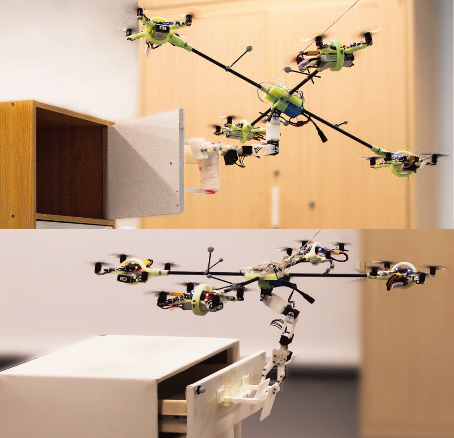
Our new UAM platform, integrated with VKC-based planning framework and hierarchical control architecture, is demonstrated on various sequential aerial manipulation tasks involving multiple steps in simulations and physical experiments. Fig. 1 depicts an example of relocating an object into a closed drawer and a closed cabinet, requiring six manipulation steps. This experiment, for the first time, demonstrates the plausibility and potential of planning sequential aerial manipulation tasks for UAMs.
This paper makes three contributions: (i) We put forward a novel mechanical design of an over-actuated UAM and derive the dynamics model of the system. (ii) We devise a manipulation planning and hierarchical control framework for UAMs. (iii) We demonstrate UAMs’ sequential manipulation capabilities in both simulations and experiments.
The remainder of the paper is organized as follows. Sec. II presents the hardware design of our UAM platform. Secs. III, V and IV describe the system dynamics, manipulation planning, and control framework of this platform, respectively. Simulation and experimental results are summarized in Secs. VI and VII, respectively. Sec. VIII concludes the paper.
II Hardware Design
As shown in Fig. 2, our UAM platform consists of an over-actuated flying vehicle and a 4-DoF robotic manipulator connected at the bottom; it weights with a maximum payload of . Due to limited onboard computing power, the platform’s controller runs on a remote PC that wirelessly sends control commands to the platform.
II-A Flying Vehicle
The flying vehicle’s central frame is a rigid body made of a resin block fixed with four carbon-fiber tubes. Each tube is connected to an omnidirectional thrust generator with two added passive DoFs to a generic quadcopter through a 3D-printed gimbal mechanism; see Fig. 2. Each quadcopter comprises a Crazyflie 2.1 control board, a Bitcraze’s BigQuad Deck, and a power distribution board connected to an 11.1v Lithium battery. Four Emax RS1108 brushless motors actuate 3-inch propellers with a maximum thrust force of . Their speeds are controlled by an Electronic Speed Controller (ESC). This flying vehicle has been fully verified in prior work [21, 22, 23], capable of independently tracking 6-DoF position and attitude trajectory and achieving arbitrary attitude rotations with high thrust efficiency.
II-B Robotic Manipulator
The robotic manipulator is installed at the bottom of the flying vehicle. It comprises three serial rotational DoFs and a parallel gripper. Four Dynamixel XC330-M228-T motors are utilized to actuate the manipulator, and a Raspberry Pi Zero (RPi Zero) and a Dynamixel U2D2 converter are equipped on the flying vehicles to receive the control command wirelessly; RPi Zero send these signals to control the motors. The manipulator subsystem is powered by a battery. The system’s physical properties are tabulated in Tab. I.
| Group | Parameter | Value |
| flying vehicle | ||
| manipulator | ||
| griper range/ | ||
| others | remote PC control rate/ | |
| quadcopter control rate/ | ||
| manipulator control rate/ | ||
| communication delay/ |
III Dynamics Modelling
The complete dynamics model of the UAM platform is too complex for controller design; dividing it into two decoupled subsystems—the arm and the flying vehicle—introduces severe disturbance to the platform. As a result, we simplify the flying vehicle’s dynamics by concentrating on compensating the gravity torque introduced by the shift of center of mass (CoM) when the manipulator is in motion.
III-A Platform Configuration and Notation
Fig. 2 illustrates related coordination frames. The world frame and the UAM’s body frame are denoted as and , respectively. We define the body frame’s position as , the attitude in the roll-pitch-yaw convention as , and the angular velocity in as [24]. Frame is attached to the th thrust generator’s center. We combine the flying vehicle’s pose and velocity as and . Let be the manipulator’s joint angles.
III-B Flying Vehicle Dynamics
The dynamics model of the flying vehicle is simplified as:
| (1) |
where is the gravitational acceleration, the whole platform’s total mass, the whole platform’s inertia matrix, the gravitational torque due to the displacement of its CoM from the geometric center, and the unit vector in the vertical direction in the world frame. Of note, and are functions of the manipulator’s joint angles defined by kinematic relationships. And
| (2) |
where , , and denote the magnitude of thrust, tilting, and twisting angles of the th thrust generator, respectively. is the distance vector from ’s center to each .
III-C Manipulator Dynamics
The dynamics of the manipulator are modeled following Luo et al. [25], formally as:
| (3) |
where is the manipulator’s inertia matrix, the vector of the Coriolis and centrifugal terms, the gravitational force vector, the torque command of each joint actuator, external forces, and the related Jacobian matrix.
IV Sequential Aerial Manipulation Planning
In this section, we start by describing three essential steps to construct VKCs [16, 17, 26] for our UAM platform. Next, we formulate the sequential manipulation planning problem on VKCs and solve it through trajectory optimization for aerial manipulation tasks.
IV-A Modeling UAMs with VKCs
Kinematic inversion reverses the kinematic model of an articulated object by converting the attachable link into the new root in the inverted kinematic model. Of note, in addition to reversing the parent-child relationship for every two adjacent frames between the base link and the attachable link of the object, the spatial transformation of each joint must also be updated appropriately since a joint typically constrains the child link’s motion w.r.t. child link’s frame.
Virtual joint defines the spatial transformation between two body frames and the joint type that constrains the relative motion between them. The manipulator and the manipulated object form a single serial kinematic chain by inserting a virtual joint between the manipulator’s end-effector and an attachable link in the object model. If a manipulated object is articulate, its kinematic model has to be inverted for the constructed kinematic chain to remain serial.
Virtual base reflects the motion constraints imposed on the floating base. In our UAM platform, the floating base is an over-actuated UAV that can achieve free motion in space. Specifically, starting from the ground, we add three perpendicular prismatic joints for linear motion, followed by three revolute joints at the center of the UAV body frame for angular motions. These six joints together form a virtual chain that mimics the possible motions of the floating base.
A VKC for aerial manipulation planning is constructed by augmenting a virtual base to the UAM’s kinematic model; see Fig. 2. During the manipulation, the end-effector connects to the inverted object model via a virtual joint. From this VKC perspective, performing an aerial manipulation task is treated as altering the VKC’s state, equivalent to solving a motion planning problem on VKCs.
IV-B Motion Planning on VKCs
The state vector describes the state of a VKC, where is the collision-free configuration space. The motion planning problem on VKCs is equivalent to finding a -step path , which can be formulated and solved by trajectory optimization. Following Jiao et al. [16, 17], the objective function of the trajectory optimization is:
| (4) |
where we penalize the overall traveled distance and overall smoothness of the trajectory . and are two diagonal weighting matrices for each DoF, and are finite forward difference and second-order finite central difference of , respectively. An equality constraint is imposed on the constructed VKC, which specifies the physical constraints of the object or the environment:
| (5) |
Failing to account for this type of constraint (e.g., the kinematic constraint of the manipulator or the object) may damage the UAM or the object being manipulated, resulting in failed executions.
The goal of a sequential aerial manipulation task is formulated as an inequality constraint:
| (6) |
which bounds the final state of the VKC and the task goal with a small tolerance . The function maps from the configuration space to the task-dependent goal space . For example, in an object-picking task, represents the forward kinematics of the VKC, and is the end-effector pose prior to grasping [27].
Additional safety constraints are further imposed on the motion planning problem:
| (7) | ||||
| (8) | ||||
| (9) | ||||
| (10) |
where is defined as . Eqs. 7 and 8 are inequality constraints that define the joint capability and implicitly constrain the workspace of a UAM. Eqs. 9 and 10 penalize collisions with obstacles and self-collisions, respectively. is a predefined safety distance, and is a function that calculates the signed distance between a pair of objects.
V Control
Using a hierarchical control architecture, we devise the UAM’s overall controller with two subsystems, shown in Fig. 3. The high-level controller calculates the desired commands for trajectory tracking remotely and sends them wirelessly to the low-level controller that runs on the platform with high frequency.
V-A Flying Vehicle Control
High-level control
The feedback-linearization method is applied to Eq. 1 to transfer the nonlinear system dynamics to a linear double integrator [28, 29, 30]:
| (11) |
where the superscript indicates the desired values, and are two virtual inputs that can be designed with translational and rotational errors to track the reference position and attitude trajectory:
| (12) | ||||
where and are constant gain matrices, and the superscript indicates the reference value from the VKC-based motion planning; see Sec. IV. The error terms are defined following Su et al. [31]:
| (13) | ||||
where is the transformation from Euler angles to a standard rotation matrix, and is the mapping from SO(3) to . Combining Eqs. 11, 12 and 13 with Eq. 1, we have the error dynamics as:
| (14) | ||||
which is an asymptotically stable system.
Control allocation and low-level control
The control allocation solves for desired command , , and for each 3-DoF thrust generator from total wrench command of whole flying vehicle . Among various approaches [22, 28, 20, 21, 32], we implement the downwash-aware control allocation method [21] to avoid the large disturbance caused by downwash flows that counteract other thrust generators while maintaining high thrust efficiency, critical for a smooth aerial manipulation, especially when interacting with an object.
In low-level control, two separated PID controllers are designed to allow each quadcopter to track the desired tilting and twisting angles, and , with tilting torque commands. This is combined later with the thrust force command to determine each actuator’s angular velocity. Finally, it is converted to a PWM command to drive the actuators [22].
V-B Manipulator Control
With Eq. 3, we design the manipulator’s controller,
| (15) |
where
| (16) | ||||
where are constant gain matrices.
VI Simulation
VI-A Setup
Before conducting experiments, we developed a simulation platform in MATLAB Simulink/Simscape to evaluate the proposed sequential manipulation planning framework on our customized over-actuated UAM platform [33, 34]. To realistically replicate the physical system, the simulator incorporates the UAM’s physical parameters, the dynamics of propeller motors and saturation, control frequencies, communication noise, measurement noise, and delays; see Tab. I.
VI-B Results
Figs. 4 and 5 summarize the simulation results of accomplishing two sequential aerial manipulation tasks—installing a light bulb and relocating an object into a closed cabinet—using the proposed manipulation planning framework.
Task 1
As shown in Fig. 4(a), the light bulb installation task was divided into four steps in our VKC-based motion planning framework: ① approach the light bulb, ② pick it up with the manipulator, ③ flip the platform to transport the light bulb to the bottom of the target position, and ④ move up to install it. A 10-DoF VKC for the UAM platform is built—six for the flying vehicle and four for the manipulator. A feasible and collision-free reference trajectory is acquired within the physical constraints. As shown in Fig. 4(b), with the hierarchical controller introduced in Sec. V, the proposed UAM platform can accurately track the reference trajectory to accomplish the task.
Task 2
Relocating an object into the cabinet requires a six-step action sequence of the UAM: ① approach the door and grasp the handle with the manipulator, ② open the door, ③ ungrasp the handle and move to pick up the object, ④ put the object into the cabinet, ⑤ approach and grasp to the handle again, and ⑥ close the door. Some keyframes are shown in Fig. 5, and the planned reference trajectory by the VKC-based motion planner and the tracking performance are shown in Fig. 5(b).
These simulation results indicate that the VKC-based motion planning framework and the proposed UAM platform effectively achieve sequential aerial manipulation.
VII Experiment
VII-A Setup
To further demonstrate the sequential aerial manipulation capability, we conduct experiments by implementing a table arrangement task in the physical world. Specifically, we use the Vicon motion capture system (MoCap) to measure the position and attitude of the UAM platform. The trajectory planner and main controller of the UAM systems runs on a remote PC (AMD Ryzen9 5950X CPU, 64 GB RAM), which communicates with the MoCap through Ethernet and efficiently solves the controller commands. The flying vehicle’s primary controller is modified from the Crazyflie python library; it calculates the desired thrust , tilting angles , and twisting angles for all quadcopter modules of the thrust generators and sends them through Crazy Radio PA antennas (2.4G ). Each quadcopter is embedded with an onboard IMU module. Its firmware is modified to estimate the rotation angle given the attitude of central frame , regulates the tilting and twisting angles to desired values with two PID loops, and provides the required thrust with 500 for a fast low-level response.
The manipulator controller is modified from the Robotis Dynamixel SDK, which runs on the RPi Zero. It wirelessly receives commands from the remote PC and sends commands to the motors through the Dynamixel U2D2 converter. Each Dynamixel XC330-M228-T motor has its own controller, and the control mode is set as current control. The measurement rate of the motion capture system, the remote PC controller, and the data communication with the UAM platform is all set to 100 .
VII-B Results
Fig. 6 summarizes the experimental results of relocating an object into the drawer, which was divided into six steps: ① approach to the drawer and grasp the handle with the manipulator, ② open the drawer, ③ ungrasp with the handle and move to pick up the toy, ④ move to the opened drawer and drop off the toy inside, ⑤ approach and grasp the handle again, and ⑥ close the drawer. The 10-DoF reference trajectory provided by our VKC-based motion planner was accurately tracked by the UAM with the hierarchical controller, and the desired commands for each omnidirectional thrust generator are plotted in Fig. 6(b). Figs. 1 and 6(a) show some experiment keyframes.
VIII Conclusion
In this paper, we presented a solution to the sequential aerial manipulation problem of UAMs, an unexplored topic until now. Unlike previous work in UAM that solves the motion planning and control problems of one-step manipulation tasks, accomplishing sequential aerial manipulation requires (i) a highly efficient UAM platform, (ii) a specialized motion planner that can well-coordinate motions of the flying vehicle, the manipulator, and the manipulated object under varied settings, and (iii) an effective control scheme to track the desired trajectory. To jointly tackle these challenges, we designed a novel UAM platform based on an over-actuated UAV that can achieve omnidirectional flight with high thrust efficiency. To produce a long sequence of motions that coordinates well with each other, we extended the idea of VKC used for ground mobile manipulators and developed a VKC-based aerial manipulation planning framework for UAMs. Together with a hierarchical control scheme, we validated our solution in both simulation and experiment. The results demonstrated that our approach endowed a new capability of sequential aerial manipulation for UAMs and could open up new venues in the field of aerial manipulation.
The integration of a wireless tactile senor [35, 36] with the manipulator will be the future work for our research, which extends the manipulation capability of our UAM platform and enlarges the application range of our the VKC-based planning framework to more complicated sequential aerial manipulation tasks.
Acknowledgement: We thank Dr. Zeyu Zhang (BIGAI), Zhen Chen (BIGAI), Yangyang Wu (BIGAI), Zihang Zhao (BIGAI), Hao Liang (BIGAI), and Qing Lei (PKU) for their help on Vicon, figures, and hardware design. This work is supported in part by the National Key R&D Program of China (2021ZD0150200) and the Beijing Nova Program.
References
- [1] M. Fumagalli, R. Naldi, A. Macchelli, F. Forte, A. Q. Keemink, S. Stramigioli, R. Carloni, and L. Marconi, “Developing an aerial manipulator prototype: Physical interaction with the environment,” IEEE Robotics and Automation Magazine (RA-M), vol. 21, no. 3, pp. 41–50, 2014.
- [2] A. Ollero, M. Tognon, A. Suarez, D. Lee, and A. Franchi, “Past, present, and future of aerial robotic manipulators,” Transactions on Robotics (T-RO), 2021.
- [3] M. Ryll and R. K. Katzschmann, “Smors: A soft multirotor uav for multimodal locomotion and robust interaction,” in International Conference on Robotics and Automation (ICRA), 2022.
- [4] G. Jiang, R. Voyles, K. Sebesta, and H. Greiner, “Estimation and optimization of fully-actuated multirotor platform with nonparallel actuation mechanism,” in International Conference on Intelligent Robots and Systems (IROS), 2017.
- [5] S. Park, J. Lee, J. Ahn, M. Kim, J. Her, G.-H. Yang, and D. Lee, “Odar: Aerial manipulation platform enabling omnidirectional wrench generation,” Transactions on Mechatronics (TMECH), vol. 23, no. 4, pp. 1907–1918, 2018.
- [6] S. Yi, K. Watanabe, and I. Nagai, “Modeling and control of a fully-actuated quadrotor manipulator with tiltable rotors,” in Recent Advances in Intelligent Computational Systems (RAICS), 2020.
- [7] M. Zhao, K. Okada, and M. Inaba, “Versatile articulated aerial robot dragon: Aerial manipulation and grasping by vectorable thrust control,” International Journal of Robotics Research (IJRR), p. 02783649221112446, 2022.
- [8] M. Tognon, E. Cataldi, H. A. T. Chavez, G. Antonelli, J. Cortés, and A. Franchi, “Control-aware motion planning for task-constrained aerial manipulation,” IEEE Robotics and Automation Letters (RA-L), vol. 3, no. 3, pp. 2478–2484, 2018.
- [9] K. Bodie, M. Tognon, and R. Siegwart, “Dynamic end effector tracking with an omnidirectional parallel aerial manipulator,” IEEE Robotics and Automation Letters (RA-L), vol. 6, no. 4, pp. 8165–8172, 2021.
- [10] M. Zhao, K. Nagato, K. Okada, M. Inaba, and M. Nakao, “Forceful valve manipulation with arbitrary direction by articulated aerial robot equipped with thrust vectoring apparatus,” IEEE Robotics and Automation Letters (RA-L), vol. 7, no. 2, pp. 4893–4900, 2022.
- [11] M. Brunner, G. Rizzi, M. Studiger, R. Siegwart, and M. Tognon, “A planning-and-control framework for aerial manipulation of articulated objects,” IEEE Robotics and Automation Letters (RA-L), 2022.
- [12] N. Sugito, M. Zhao, T. Anzai, T. Nishio, K. Okada, and M. Inaba, “Aerial manipulation using contact with the environment by thrust vectorable multilinked aerial robot,” in International Conference on Robotics and Automation (ICRA), 2022.
- [13] D. Berenson, J. Kuffner, and H. Choset, “An optimization approach to planning for mobile manipulation,” in International Conference on Robotics and Automation (ICRA), 2008.
- [14] S. Chitta, B. Cohen, and M. Likhachev, “Planning for autonomous door opening with a mobile manipulator,” in International Conference on Robotics and Automation (ICRA), 2010.
- [15] K. Gochev, A. Safonova, and M. Likhachev, “Planning with adaptive dimensionality for mobile manipulation,” in International Conference on Robotics and Automation (ICRA), 2012.
- [16] Z. Jiao, Z. Zhang, X. Jiang, D. Han, S.-C. Zhu, Y. Zhu, and H. Liu, “Consolidating kinematic models to promote coordinated mobile manipulations,” in International Conference on Intelligent Robots and Systems (IROS), 2021.
- [17] Z. Jiao, Z. Zhang, W. Wang, D. Han, S.-C. Zhu, Y. Zhu, and H. Liu, “Efficient task planning for mobile manipulation: a virtual kinematic chain perspective,” in International Conference on Intelligent Robots and Systems (IROS), 2021.
- [18] J. Haviland, N. Sünderhauf, and P. Corke, “A holistic approach to reactive mobile manipulation,” IEEE Robotics and Automation Letters (RA-L), 2022.
- [19] A. Röfer, G. Bartels, W. Burgard, A. Valada, and M. Beetz, “Kineverse: A symbolic articulation model framework for model-agnostic mobile manipulation,” IEEE Robotics and Automation Letters (RA-L), 2022.
- [20] Y. Su, P. Yu, M. Gerber, L. Ruan, and T.-C. Tsao, “Nullspace-based control allocation of overactuated uav platforms,” IEEE Robotics and Automation Letters (RA-L), vol. 6, no. 4, pp. 8094–8101, 2021.
- [21] Y. Su, C. Chu, M. Wang, J. Li, Y. Liu, Y. Zhu, and H. Liu, “Downwash-aware control allocation for over-actuated uav platforms,” in International Conference on Intelligent Robots and Systems (IROS), 2022.
- [22] P. Yu, Y. Su, M. J. Gerber, L. Ruan, and T.-C. Tsao, “An over-actuated multi-rotor aerial vehicle with unconstrained attitude angles and high thrust efficiencies,” IEEE Robotics and Automation Letters (RA-L), vol. 6, no. 4, pp. 6828–6835, 2021.
- [23] P. Yu, Y. Su, L. Ruan, and T.-C. Tsao, “Compensating aerodynamics of over-actuated multi-rotor aerial platform with data-driven iterative learning control,” IEEE Robotics and Automation Letters (RA-L) (submitted), 2023.
- [24] C. Pi, L. Ruan, P. Yu, Y. Su, S. Cheng, and T. Tsao, “A simple six degree-of-freedom aerial vehicle built on quadcopters,” in Proceedings of IEEE Conference on Control Technology Applications (CCTA), 2021.
- [25] J. Luo, Z. Gong, Y. Su, L. Ruan, Y. Zhao, H. H. Asada, and C. Fu, “Modeling and balance control of supernumerary robotic limb for overhead tasks,” IEEE Robotics and Automation Letters (RA-L), vol. 6, no. 2, pp. 4125–4132, 2021.
- [26] Z. Jiao, Y. Niu, Z. Zhang, S.-C. Zhu, Y. Zhu, and H. Liu, “Sequential manipulation planning on scene graph,” in International Conference on Intelligent Robots and Systems (IROS), 2022.
- [27] Z. Jiao, A Virtual Kinematic Chain Perspective for Robot Task and Motion Planning. PhD thesis, University of California, Los Angeles, 2022.
- [28] L. Ruan, C.-H. Pi, Y. Su, P. Yu, S. Cheng, and T.-C. Tsao, “Control and experiments of a novel tiltable-rotor aerial platform comprising quadcopters and passive hinges,” Mechatronics, vol. 89, p. 102927, 2023.
- [29] Y. Su, L. Ruan, P. Yu, C.-H. Pi, M. J. Gerber, and T.-C. Tsao, “A fast and efficient attitude control algorithm of a tilt-rotor aerial platform using inputs redundancies,” IEEE Robotics and Automation Letters (RA-L), vol. 7, no. 2, pp. 1214–1221, 2021.
- [30] Y. Su, P. Yu, M. Gerber, L. Ruan, and T. Tsao, “Fault-tolerant control of an over-actuated uav platform built on quadcopters and passive hinges,” Transactions on Mechatronics (TMECH), 2023.
- [31] Y. Su, Compensation and Control Allocation with Input Saturation Limits and Rotor Faults for Multi-Rotor Copters with Redundant Actuations. PhD thesis, University of California, Los Angeles, 2021.
- [32] M. Ryll, H. H. Bülthoff, and P. R. Giordano, “A novel overactuated quadrotor unmanned aerial vehicle: Modeling, control, and experimental validation,” IEEE Transactions on Control Systems Technology, vol. 23, no. 2, pp. 540–556, 2014.
- [33] Y. Su, Z. Jiao, Z. Zhang, C. Chu, J. Li, H. Li, M. Wang, and H. Liu, “Flight structure optimization of modular reconfigurable uavs,” in International Conference on Robotics and Automation (ICRA) (submitted), 2024.
- [34] Y. Su, C. Chu, J. Zhang, H. Li, M. Wang, and H. Liu, “Marvel: Modular unmanned aerial vehicles can achieve full actuation through self-reconfiguration,” in International Conference on Robotics and Automation (ICRA) (submitted), 2024.
- [35] W. Li, M. Wang, J. Li, Y. Su, D. K. Jia, X. Qian, A. Kaspar, and H. Liu, “L3 f-touch: A wireless gelsight with decoupled tactile and three-axis force sensing,” IEEE Robotics and Automation Letters (RA-L), 2023.
- [36] H. Liu, X. Xie, M. Millar, M. Edmonds, F. Gao, Y. Zhu, V. J. Santos, B. Rothrock, and S.-C. Zhu, “A glove-based system for studying hand-object manipulation via joint pose and force sensing,” in International Conference on Intelligent Robots and Systems (IROS), 2017.