- IT
- Information Technology
- OT
- Operational Technology
- ICS
- Industrial Control System
- MBSE
- Model Based Systems Engineering
- MBT
- Model Based Testing
- SUT
- System Under Test
- CVSS
- Common Vulnerability Scoring System
- CVE
- Common Vulnerabilities and Exposure
- FSM
- Finite State Machine
- EFSM
- Extended Finite State Machine
- TA
- Timed Automata
- MCUM
- Markov Chain Usage Model
- VV
- Verification and Validation
- EDDL
- Electronic Device Description Language
- SIS
- Safety Instrumented System
A Model Based Framework for Testing Safety and Security
in Operational Technology Environments
Abstract
Today’s industrial control systems consist of tightly coupled components allowing adversaries to exploit security attack surfaces from the information technology side, and, thus, also get access to automation devices residing at the operational technology level to compromise their safety functions. To identify these concerns, we propose a model-based testing approach which we consider a promising way to analyze the safety and security behavior of a system under test providing means to protect its components and to increase the quality and efficiency of the overall system. The structure of the underlying framework is divided into four parts, according to the critical factors in testing of operational technology environments. As a first step, this paper describes the ingredients of the envisioned framework. A system model allows to overview possible attack surfaces, while the foundations of testing and the recommendation of mitigation strategies will be based on process-specific safety and security standard procedures with the combination of existing vulnerability databases.
Index Terms:
Industrial Control System, Operational Technology, Model-Based Testing, Safety and SecurityI Introduction
Over the years, automation systems have been developed considering mainly safety hazards. As automation technologies are nowadays are closely connected to Information Technology (IT) systems and former borders to Operational Technology (OT) get blurred, adversaries can start a chain of security attacks from the enterprise level and gain access to compromise the safety of Industrial Control Systems [1]. Thus, convergence with increased security flaws at the IT level opens doors for harming safety at the OT level. Investigating different methodologies is necessary to evaluate the resilience of the system against attacks on the different levels while ensuring that the system considers interdependencies of safety and security. The paper addresses the mutual dependency of engineering branches on safety and security from a model-based perspective with Model Based Systems Engineering (MBSE) and safety-security requirement engineering in mind, as these two branches of engineering are not integrated, yet. Integration of these branches can bring benefit on topics such as automated asset management, system complexity management, risk-cost assessment, multidisciplinary team management, and integrated system safety and security evaluation[13]. The proposed framework supports a methodology to define requirements and analyze the design implementation of an ICS before and after the commissioning of OT components in the system. Its purpose is to test whether the OT system meets safety and security requirements according to the underlying standards. It integrates four domains into MBSE, such as requirements/capabilities (asset information), behavior (operations/methods), structure/architecture (system modelling), verification and validation (system model testing)[2]. Input data essential for our framework are asset information, communication types between assets, operations/methods types executed by assets, and policies or safety/security measures on asset. The envisioned framework shall be able to retrieve safety and security requirements and their related measures or mitigation strategies from a database. The latter concern best practices to follow and updates to be deployed [3]. The paper is structured as follows. Section II outlines the concepts and ingredients of our model-based testing framework. Section III proposes the testing framework approach in brief and sketches an application for a small use case in Section IV. Section V draws some concluding remarks and next steps.
II Background
II-A Model Based System Engineering (MBSE)
MBSE is a formalized application of modeling to support system requirements, design analysis, verification, and validation activities starting from conceptual design and continuing throughout development, and later lifecycle phases [2]. MBSE can be beneficial in terms of reduced development cost, system quality, process, and timeline management[4].
II-B Model Based Testing (MBT)
MBT is a part of the MBSE lifecycle, which works on a deterministic system and demonstrates the implementation’s behavior. The most challenging parts for MBT are the development of automated test case generation, creation of test data, and definitions of procedures to test the system. MBT has proven to increase the quality and efficiency of the system by behavioral analysis of System Under Test (SUT) models. Once these models have been ensured to reflect the system requirements, these scenarios can serve as ideal test cases in the testing phase [5].
II-C Vulnerability Assessment
The vulnerability assessment focuses on criticality, OT components’ current vulnerabilities, and mitigation. The assessment includes details such as the severity of a threat and a corresponding risk level, determined by, e.g., Common Vulnerability Scoring System (CVSS) or Common Vulnerabilities and Exposure (CVE) references, which can be retrieved from vulnerability databases. Moreover, suggestions of mitigation strategies can be part of it, such as available updates and information about patches like name, release date, and update type. Before updates are done, integrity checks need to be carried out [3].
II-D Test Case Generation
The proposed framework will address automated test case generation using state-based models, which may include Finite State Machines, Extended Finite State Machines, UML State Machine Diagrams, Timed Automatas, and Markov Chain Usage Models. At the moment, individual benefits of these test generation techniques are investigated. FSMs can be used to generate tests under sandboxing for SUT and check if corresponding tests hold for the system and protocol implementation. EFSMs can generate tests in control and data parts of the system specification. UML can be used to generate a test for multiple processes executing simultaneously in the SUT and is also suitable for unit tests based on object-oriented components. TA are the best option for test generation in a real-time system with timing constraints and model checking tools. MCUM test generation is based on the statistics of execution of states which can be used in complex system components in the SUT [5].
II-E Test Verification & Validation
The test verification and validation (V&V) is a well-defined approach that evaluates the system throughout its life cycle to the end of product life[14]. In V&V of OT systems, we considered the most relevant safety and security standards summarized in Table I. These standards serve as a basis for the definition of a protection catalog. Based on the catalog, a rule-based system will be developed to deal with the imprecision, modeling method of human behavior, and achieving control of ICSs by executing a sequence of commands which can or cannot be modeled rigorously[11].
| Criteria | Standards |
|---|---|
| Safety | IEC 61511 (Functional safety - Safety instrumented systems for the process industry sector), IEC 61311-6 (Programmable controllers - Part 6: Functional safety), IEC 61784-3 (Industrial communication networks - Profiles - Part 3: Functional safety fieldbuses - General rules and profile definitions), IEC 61508 (methods on how to apply, design, deploy and maintain automatic protection systems called safety-related systems), IEC 62061 (Safety of machinery: Functional safety of electrical, electronic and programmable electronic control systems), IEC 13849-1 (safety-related parts of a control system) |
| Safety & Security | IEC TR 63074 (Safety of machinery - Security aspects related to functional safety of safety-related control systems), IEC TR 63069 (Industrial-process measurement, control and automation - Framework for functional safety and security) |
| Security | IEC 62443 (cybersecurity for operational technology in automation and control systems), ISO/TR 22100-4 (Guidance to machinery manufacturers for consideration of related IT-security (cyber security) aspects), ISO/IEC 27002 (Information technology — Security techniques — Code of practice for information security controls) |
III Proposed Framework
The proposed semi-automated approach to the model-based testing framework for OT environments is divided into four parts illustrated in Fig.1.
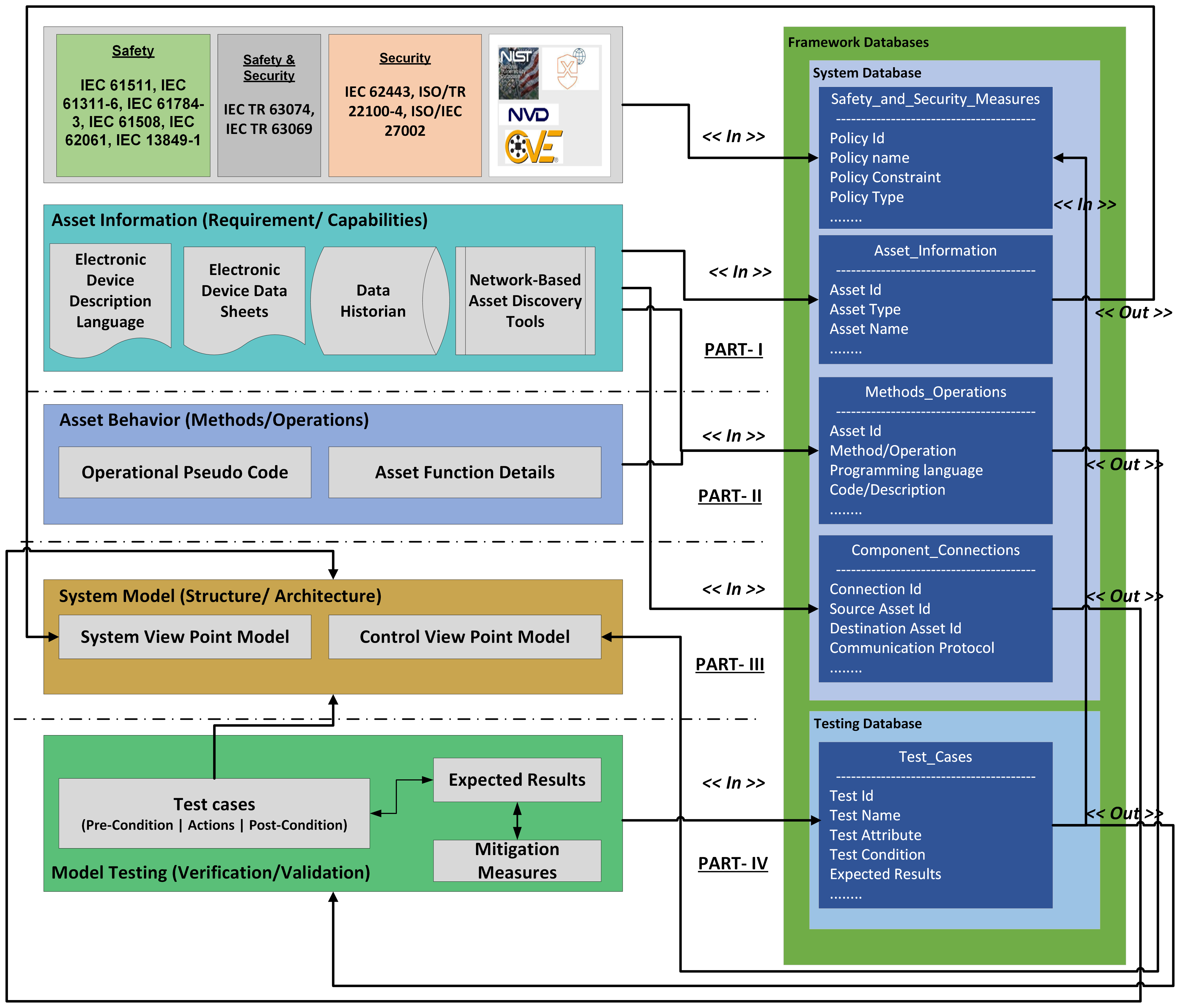
Part-I Asset Information (Requirements/Capabilities): The asset information can be extracted with a semi-automated approach from different sources such as data historians, electronic data sheets, Electronic Device Description Language (EDDL) artifacts, and network-based asset discovery tools. Data extracted from these sources are sketched in Table II. This information is stored in the system model schema in the tables asset_information, methods_operations, and component_connections.
Part-II Asset Behavior (Operations/Methods): In this part, operations or functions performed by the asset can be specified (if applicable) in the form of pseudo-code in any supported language for analyzing the asset behavior. Any attribute change from the asset components will impact the methods carrying those attributes, which must be tested. Moreover, it will be possible for developers to check whether the programming language standards are followed, for example, if IEC 61131-3 programming guidelines are met. Additionally, a user can describe the pseudo-code for the operation to be performed by the PLC. The pseudo-code can be validated against the user-defined policies based on programming language standards, such as found in the table safety_security_measures from the database. These operations/functions are stored in the table methods_operations.
Part III System Modelling (Structure/Architecture): After collecting details of system components (i.e., asset information, methods/operations, and components connection), the next step is to build a system model from two viewpoints: (1) the System View Point is associated with the management of the sub-system along with the component attributes and holds all static information. (2) the control view point provides the perspective when the system operates and is administered. Thus, the control viewpoint includes the behavioral part of a system generated using table methods_operations, while the system viewpoint holds information about the individual asset components using asset_information. The cardinality and relation between asset components class is maintained by the table component_connection. The final model will be based on SysML or Automation ML[12].
Part-IV Model Testing (Verification and Validation): The verification and validation of the system model are performed on the rule-based system description (cf. Subsection II-E). The rule-based approach allows a tester to check whether the expected ideal condition is met, as defined in the table test_cases. These ideal conditions are validated against the test cases to check whether the system satisfies the required pre-condition, actions, and post-condition with the expected results. Test cases are input to the compiled model (cf. Subsection II-D). After testing, if validation fails, required mitigation measures are suggested for successful validation, and changes can be visualized in the system model.
| Approach | Information |
|---|---|
| Data Historian [6, 7] | Plant/process/asset information, asset location, asset specification, sensor readings, product (quality) information, recorded alarms, aggregated data, … |
| Electronic Datasheet [8] | Configuration details, network ports, communication object details, services |
| EDDL[9] | Parameter definitions, vendor-specific definitions (manufacturer, device type, revision), parameters, device features |
| Network Based Asset Discovery Tools[10] | Asset Information, Connection type, Communication Protocols |
IV Illustrative Example
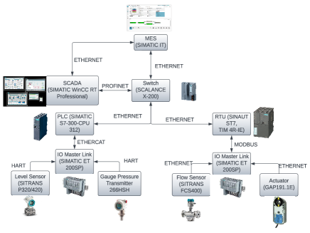
A simple use case of an ICS shall illustrate the implementation of the envisioned framework. The use case (Fig.2) consists of OT components up to level 4 of the Purdue model[15] with sensors, actuators, IO masters, PLCs, RTUs, switches, and workstations. The software side executes firmware, PLC code, SCADA, and MES. Using different techniques mentioned in Table II, we extract asset information for Part-I and Part-II of the framework. In Part-I, discovered asset type and asset name information shown in Table V are gathered using data historian and network-based asset discovery tools. For the connections of asset components, we can use network-based discovery tools, electronic data sheets, and information from EDDL consisting of connection information of the source and destination asset, and communication protocols shown in Table VII. In Part II, we extract relevant method information of assets using data historian, electronic data sheets, and EDDL data consisting of an operation name. The programming language used to run the operation (if applicable) and a description can be a pseudo code or range of values shown in Table VI. In Part III, the framework retrieves extracted system information for generating the system and control viewpoint models in SysML or Automation ML. The system viewpoint model is generated using Tables V and VII, while the control viewpoint model is generated using Tables V and VI. In Part IV, first, we generate a test case, for example, to test a Safety Instrumented System (SIS) functionality with a PLC (H07) as target. Here test attributes will be an input to automated test case generation (cf. Subsection II-D). As shown in Table IV, the pre-condition, action, post-condition, and expected result of the test will be fetched. Post-conditions and tester-defined expected results are compared to validate whether the test succeeded or failed. In this example, the expected results and post-conditions are the same, implying a successful validation. In case of a failure, mitigation policies/measures from Table III are required. As we are testing the SIS functionality of the PLC, policies related to safety are recommended (i.e., P01). If the recommended mitigations are fulfilled, then changes are reflected in the model, as shown in Part III of the framework.
| Policy ID | Policy Name | Policy Constraint | Policy Type |
|---|---|---|---|
| P01 | IEC 61511: Functional Safety Management | Bypass Power functions; start-up power override; manual shutdown systems; proof-test intervals are documented in the maintenance procedures; diagnostic alarm functions perform as required; utilities are restored, the safety instrumented system returns to the desired state | Safety |
| P02 | IEC 62443: Patch Management | SIMATIC IT Production Suite (CVE-2018-13804) (Versions V7.1 V7.1 Upd3) (CVSS Score 9.3); mitigation - restrict network access to affected installations | Security |
| P03 | IEC TR 63074: Security aspects of functional safety | Identify devices covered for vulnerability assessment that could be exploited by threats and influence safety-related control systems | Safety & Security |
| Test ID | Test Name | Test Attribute | Test Condition | Expected Results |
|---|---|---|---|---|
| T01 | SIS Power Safety | PLC (H07) | PRE- Setting and adjustments of PLC logic. ACTION- Perform operations - reset, shutdown in different inputs. POST- Execute power command and yield output values | Output value is within specified range. |
| T02 | MES Version Test | SIMATIC IT (MES) - S02 | PRE- – Sandboxing of MES ACTION- Current Version Check POST- Current Version V7.0 Updated Version V7.1 | Current Version = Updated Version |
| Asset ID | Asset Type | Asset Name |
|---|---|---|
| H01 | Hardware | Level Sensor (SITRAN SP320/420) |
| H02 | Hardware | Gauge Pressure Transmitter 266HSH |
| H03 | Hardware | Flow Sensor (SITRANS FCS400) |
| H04 | Hardware | Actuator (GAP191.1E) |
| H05 | Hardware | IO Link Master (SIMATIC ET200SP) |
| H06 | Hardware | IO Link Master (SIMATIC ET200SP) |
| H07 | Hardware | PLC (SIMATICS7-300-CPU312) |
| H08 | Hardware | RTU (SINAUTST7,TIM 4R-IE)) |
| H09 | Hardware | Switch (SCALANCE X-200) |
| H10 | Hardware | Workstation |
| H11 | Hardware | Workstation |
| S01 | Software | SCADA (SIMATIC WinCC RT Professional) |
| S02 | Software | MES (SIMATIC IT) |
| S03 | Software | Linux Operating System |
| S04 | Software | Windows 10 Operating System |
| Asset ID | Method/Operation | Code/Description |
|---|---|---|
| H02 | Pressure Range | from 20 mbar to 700 bar |
| H02 | Temperature Range | from -40 °C to +100 °C |
| S01 | Monitor Client | Displays statistics of operations quantifying measurements & debugging activities |
| S02 | Data Archive | Achieving values of objects from communication, calculated values, manually entered, or other. |
| Connection ID | Source Asset ID | Destination Asset ID | Communication Protocol |
|---|---|---|---|
| C01 | H01 | H05 | HART |
| C02 | H02 | H05 | HART |
| C03 | H03 | H06 | ETHERNET |
| C04 | H04 | H06 | ETHERNET |
| C05 | H05 | H07 | ETHERCAT |
| C06 | H06 | H08 | MODBUS |
| C07 | H07 | H09 | ETHERNET |
| C08 | H08 | H09 | ETHERNET |
| C09 | H09 | S01+S02+H10 | PROFINET |
| C10 | H09 | S04+S02+H11 | ETHERNET |
| C11 | S01+S02+H10 | S04+S02+H11 | ETHERNET |
V Conclusion and Future Work
The paper attempts to present a model-based testing framework for the safety and security of OT systems. The test framework is expected to resolve the safety and security flaws in ICSs generated due to a lack of synchronization among different development teams and provide the mitigation for flaws detected based on the system model. Fulfilling the prospects of legacy and modern systems on a component level and helping to optimize the system aligned with Industry 4.0. Further implementation of the framework from design to an actual prototype will be considered important as it will involve fundamental challenges such as dynamic automation technology needs, resource optimization, modeling techniques, and adhering to safety and security standards. We plan to expand the scope of the safety and security measures/policies on a generic level. This way, we might achieve its deployment in multi-domain industries considering the specific needs of those domains, leading to a better evaluation of system components. For this step, the involvement of industry partners is necessary with the ultimate goal of developing a generic meta-model from which a system model in the framework can be derived.
Acknowledgement
This paper was supported by TÜV AUSTRIA #SafeSecLab Research Lab for Safety and Security in Industry, a research cooperation between TU Wien and TÜV AUSTRIA.
References
- [1] J. J. McCarthy, L. Acierto, J. Kuruvilla, T. Ogunyale, N. Urlaub, J. Wiltberger, and D. Wynne, “Energy Sector Asset Management: For Electric Utilities, Oil & Gas Industry,” NIST, 19-May-2020.
- [2] Fernando Aguado Agelet, Andrés Eduardo Villa,Introduction, Editor(s): Chantal Cappelletti, Simone Battistini, Benjamin K. Malphrus, Cubesat Handbook, Academic Press,2021, pp. 1-31.
- [3] Bodungen, C., Singer, B., Shbeeb, A., Wilhoit, K. & Hilt, S. Hacking Exposed Industrial Control Systems: ICS and SCADA Security Secrets & Solutions. (McGraw-Hill Education,2016),pp. 15-64.
- [4] D. D. Walden, G. J. Roedler, K. Forsberg, R. D. Hamelin, and T. M. Shortell, Systems engineering handbook: A guide for system life cycle processes and activities. Hoboken, NJ: Wiley, 2015.
- [5] A. Sabbaghi and M. R. Keyvanpour,”State-based models in model-based testing: A systematic review,”2017 IEEE 4th International Conference on Knowledge-Based Engineering & Innovation(KBEI),2017, pp. 942-948
- [6] Jim Crompton. “Chapter 5-Data Management from the DCS to the Historian”.In: Machine Learning and Data Science in the Oil and Gas Industry. Ed. by Patrick Bangert. Gulf Professional Publishing, 2021, pp. 83–110
- [7] B.R. Mehta and Y.J. Reddy. “Chapter 22 - Database systems”. In: Industrial Process Automation Systems. Ed. by B.R. Mehta and Y.J. Reddy. Oxford: Butterworth-Heinemann, 2015, pp. 583–592
- [8] R. Zurawski, “Chapter 3 - Configuration and Management of Networked Embedded Devices,” in Industrial Communication Technology Handbook, Boca Raton, FL: CRC Press, 2017, pp. 3.8-3.13.
- [9] B.R. Mehta and Y.J. Reddy. “Chapter 16 - Asset management systems”. In: Industrial Process Automation Systems. Ed. by B.R. Mehta and Y.J. Reddy. Oxford:Butterworth-Heinemann,2015, pp. 479–506.
- [10] “Discovery,” Discovery - attackics. [Online]. Available: https://collaborate.mitre.org/attackics/index.php/Discovery. [Accessed: 14-Jul-2022].
- [11] J. A. Bernard, “Use of a rule-based system for process control,” IEEE Control Systems Magazine, vol. 8, no. 5, pp. 3–13, 1988.
- [12] R. Drath, Automationml: A practical guide. DE GRUYTER OLDENBOURG, 2021.
- [13] D. Mažeika and R. Butleris, “Integrating security requirements engineering into MBSE: Profile and guidelines,” Security and Communication Networks, 12-Mar-2020
- [14] D. Ota, P. Charchalakis and E. Stipidis, ”Towards a verification and validation test framework for open system architectures,” 2017 International Conference on Military Technologies (ICMT), 2017, pp. 115-122
- [15] Theodore J. Williams. The Purdue Enterprise Reference Architecture - A Technical Guide for CIM Planning and Implementation, 1992.