Discovery of antiferromagnetic chiral helical ordered state in trigonal GdNi3Ga9
Abstract
We have performed magnetic susceptibility, magnetization, and specific heat measurements on a chiral magnet GdNi3Ga9, belonging to the trigonal space group (#155). A magnetic phase transition takes place at = 19.5 K. By applying a magnetic field along the axis at 2 K, the magnetization curve exhibits two jumps at kOe and = 45 kOe. To determine the magnetic structure, we performed a resonant X-ray diffraction experiment by utilizing a circularly polarized beam. It is shown that a long-period antiferromagnetic (AFM) helical order is realized at zero field. The Gd spins in the honeycomb layer are coupled in an antiferromagnetic manner in the plane and rotate with a propagation vector = (0, 0, 1.485). The period of the helix is 66.7 unit cells ( nm). In magnetic fields above 3 kOe applied perpendicular to the helical axis, the AFM helical order changes to an AFM order with = (0, 0, 1.5).
I Introduction
Asymmetry in space and time often plays an important role in unconventional physical phenomena. Chirality is a property of asymmetry essential in cross-disciplinary subjects and nature at all large scales. In structures with chirality, there are two types of structures, i.e., left- and right-handed mirror copies. The difference in chirality, or the handedness, of crystals often appears in macroscopic physical properties. In magnets, chiral symmetry breaking in crystal structures plays an essential role in stabilizing a macroscopic ordering state with left- or right-handed incommensurate twists of magnetic spins.
Magnetic structures reflecting the crystal chiralities have been identified mainly in electron systems and have been actively studied. The skyrmion lattice, which is a magnetic vortex, is observed in MnSi Mühlbauer et al. (2009), and a uniaxial helical magnetic structure with a periodic arrangement of ”twists”, which is called a chiral soliton lattice (CSL), is observed in CrNb3S6 Togawa et al. (2012, 2016).
Recently, chiral magnets have been explored in 4 electron system. The examples are uniaxial helical magnetic structures in YbNi3Al9 Ohara et al. (2011); Matsumura et al. (2017), DyNi3Ga9 Ninomiya et al. (2017); Ishii et al. (2018, 2019); Tsukagoshi et al. (2022), and GdPt2B Sato et al. (2022), and the skyrmion lattices in EuPtSi Kakihana et al. (2018, 2019); Tabata et al. (2019); Sakakibara et al. (2019). The period of the helical magnetic structure in 4 chiral magnet, for example in YbNi3Al9 and EuPtSi, is approximately an order of magnitude smaller than that in electron systems Togawa et al. (2016). In the case of the helical magentic order of YbNi3Al9, the angle between neighboring spins along the axis are more than 90 degrees, indicating that the exchange interaction is mediated predominantly by the conduction electrons (the Ruderman-Kittel-Kasuya-Yosida mechanism), and the weak Dzyaloshinskii-Moriya (DM)-type antisymmetric exchange interaction selects the sense of rotation.
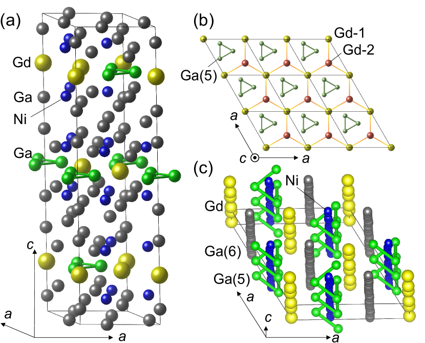
The target substance of this study is GdNi3Ga9 Topertser et al. (2019), with the same crystal structure as YbNi3Al9, which has a ErNi3Al9-type crystal structure with a space group 32 (#155) Nakamura et al. (2020). Figure 1 shows the crystal structure of GdNi3Ga9. We call this structure as right-handed and the mirror image of this structure as left-handed. The handedness can be judged by the Flack parameter of single crystal x-ray experiments. The lattice constants are 0.7264 and 2.7497 nm. The crystal structure of GdNi3Ga9 is characterized by the honeycomb layers of rare earth elements stacked along the helical axis, as shown in Figs. 1(a) and 1(b). Note that the Sohncke type space group 32 is not chiral, but the crystal structure has a chirality. Ga and Ni atoms form spirals, as shown in Fig. 1(c).
Gd compounds are suitable for investigating chiral magnetism because of the zero orbital angular momentum of Gd3+ (, , , , and ). This reduces the effects of crystal-field anisotropy and allows the magnetic moments of Gd to direct to any favorable directions determined by the exchange interactions.
Although neutron diffraction experiments are usually used to investigate the magnetic structure Ishida et al. (1985); Yamasaki et al. (2007), detailed data collection for Gd compounds is difficult because Gd is a strong neutron absorber. To observe the helical magnetic structure and the helicity of GdNi3Ga9, we performed resonant x-ray diffraction (RXD) using circularly polarized x-rays Sutter et al. (1997); Fabrizi et al. (2009); Sagayama et al. (2010).
II Experimental Procedure
We synthesized a single crystalline GdNi3Ga9 by the flux method using gallium as the solvent. The starting materials Gd ingot (purity of 99.9 %), Ni ingot (99.999 %), and Ga ingot (99.9999 %) were prepared in a molar ratio of Gd: Ni: Ga = 1: 3: 30. These materials were placed in an alumina crucible and then sealed into a quartz tube under high vacuum Pa. The ampule was heated to 900∘C and maintained at this temperature for 5 hours. Then, it was slowly cooled at a rate of 5∘C/h. The excess gallium was removed by centrifugation at 500 ∘C.
In this work, the magnetization and specific heat measurements have been performed using a commercial magnetic properties measurement system (MPMS, Quantum Design) and physical properties measurement system (PPMS, Quantum Design). The specific heat was measured between 2 and 300 K at zero magnetic field, and the magnetization was measured between 2 and 300 K in magnetic fields up to 5.5 T.
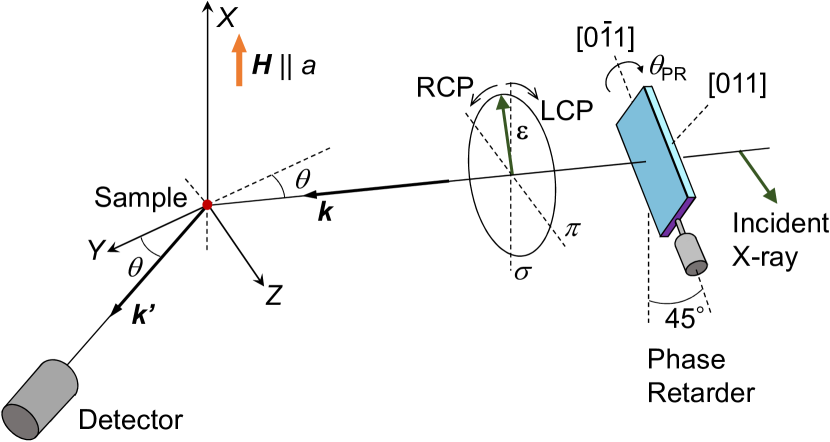
The RXD experiments were performed at BL-3A, Photon Factory at KEK, Japan. The sample with a mirror polished plane surface was inserted into an 8 T cryo-magnet and cooled down to 3 K. In this paper, the plane denotes the (001) plane. The axis was perpendicular to the magnetic field. The scattering geometry is shown in Fig. 2. A diamond phase retarder system was used to tune the horizontally polarized incident beam to a circularly polarized state Matsumura et al. (2017). A phase difference of the incident x-ray between the and polarization is generated by rotating the angle of the diamond phase plate around the 111 Bragg angle , which is 22.3∘ at 7.932 keV, where the scattering plane is tilted by 45∘. We can tune the incident linear polarization to right-handed circular polarization (RCP) and left-handed circular polarization (LCP) by changing , where .
We used an x-ray beam with a wavelength of 0.1711 and 0.1563 nm (7.246 and 7.932 keV), which are near the and edges of Gd, respectively. In GdNi3Ga9, the (1, 0, 3+1) reflections are allowed and the (1, 0, 3) and (1, 0, 31) reflections are forbidden, because of the selection rule derived from the crystal symmetry.
III Results and Analysis
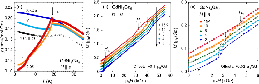

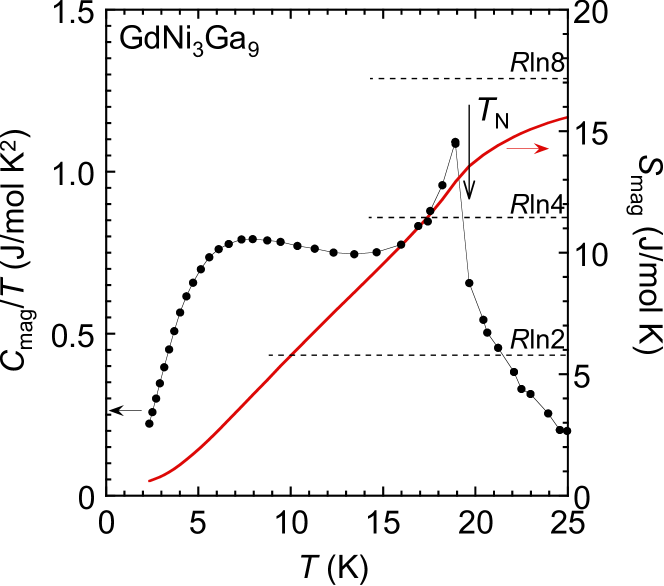
Figure 3(a) shows the temperature dependence of magnetic susceptibility () of GdNi3Ga9, which was measured at 0.05, 1, 10, and 50 kOe applied along the axis (). In this figure, for at 1 kOe is also shown. This result suggests that the Gd spins in a honeycomb layer of Fig. 1(b) are antiparallel to each other below 19.5 K. As shown afterwards, this material exhibits antiferromagnetic (AFM) helical order where magnetic propagation vector . At low magnetic fields of 0.05 and 1 kOe, a characteristic cusp is observed just below , and decreases monotonically with decreasing temperature. This cusp is similar to the one theoretically predicted to appear when the chiral helix is realized Kishine et al. (2005); Kousaka et al. (2007). This anomaly is not observed in . As the magnetic field is increased, the behavior of curve changes below . At 10 kOe, decreases below and then increases slightly at low temperatures. At 50 kOe, bending of due to AFM ordering becomes gradual. Warming from to room temperature, curve of this material is in good agreement with the Curie-Weiss law, and the Curie-Weiss temperature is estimated to be 8.7 and 11.2 K for the and axes, respectively. Although not shown in this paper, this material is isotropic in the plane, and similar magnetization curves are obtained when a magnetic field is applied in the direction.
Figure 3(b) shows magnetization curves measured at 2, 4, 6, 10, and 15 K. All magnetization curves jump twice at kOe and kOe. Except for these two jumps, magnetization increases linearly. With increasing temperature, and shift toward higher and lower magnetic fields, respectively. Figure 3(c) shows an enlarged view of the low magnetic field region in Fig. 3(b). In this figure, we can see the shift of to the high field side with increasing temperature. The metamagnetic behavior at critical magnetic fields during the linearly increasing magnetization process is a feature that appears in the magnetization process of the AFM helix when a magnetic field is applied perpendicular to the helix axis. Kishine et al. (2005); Kousaka et al. (2007)
Figure 4 shows the phase diagram of GdNi3Ga9 for obtained by the magnetization measurements. The magnetically ordered phases are named , , and phases in the order from low to high fields. and are located between the and phases, and the and phases, respectively. phase changes to the forced-ferromagnetic state at 200 kOe, when we assume that the magnetization curve of Fig. 3(b) behaves linearly up to 7, the saturation magnetization of Gd3+. As will be discussed later, the phase is an AFM helical phase, and the and phases are an AFM phase.
Figure 5 shows the temperature dependence of specific heat divided by temperature () at zero field, together with the entropy (). is obtained by subtracting the specific heat of nonmagnetic LuNi3Ga9. is obtained from assuming that increases linearly from (, ) = (0, 0). A peak of appears just below K. The entropy is estimated to be at . Below , a shoulder peak is observed around 7 K. Such a shoulder has often been observed at around /4 in Gd3+ compounds with = 7/2 Hidaka et al. (2020); Bouvier et al. (1991), and it is attributed to a splitting of the = 7/2 multiplet due to an internal field Blanco et al. (1991).
To observe the helical magnetic structure and the magnetic helicity of GdNi3Ga9, a RXD study has been performed. The measurement was conducted for the right-handed crystal, whose structure is shown in Fig. 1. The crystal chirality is reflected in helicity of the magnetic structure by a one-by-one relationship in YbNi3Al9 Matsumura et al. (2017), and left-handed crystals are expected to describe the inverted helix of the magnetic structure of this paper.
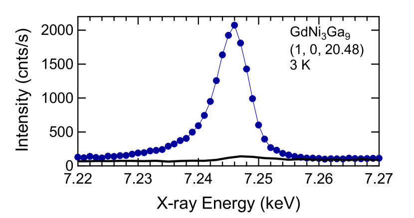
We found the resonant Bragg reflection from magnetic order at (1, 0, ) and (1, 0, ) with at 3 K. The X-ray energy dependence for the (1, 0, 20.48) peak is shown in Fig. 6. The intensity enhancement due to the resonance () is observed around the -edge of Gd, indicating that the resonant signal reflects the magnetic ordering of the Gd -spins. The peak position of the intensity is 7.246 keV. It is noted that no reflection was found along the (0, 0, ) line at (0, 0, ), indicating that the magnetic moments of the two Gd spins on the same honeycomb layer are antiparallel. The detail will be explained later.
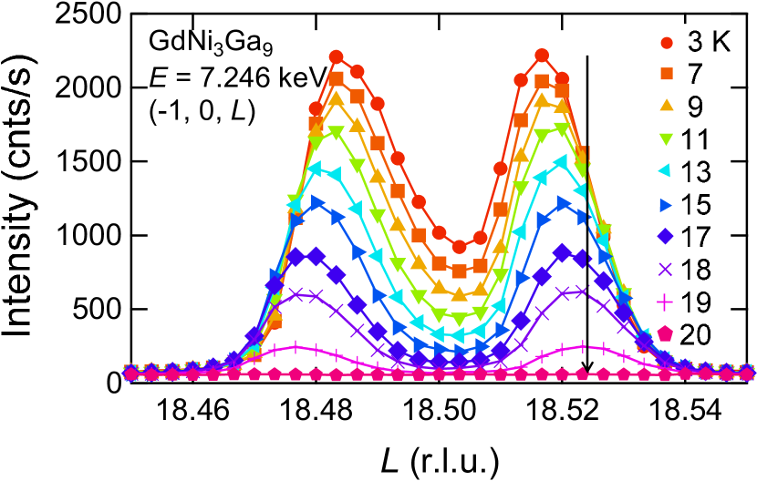
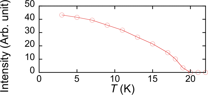
Figure 7 shows the temperature dependence of the (1, 0, ) peak profile at zero magnetic field in the AFM helical phase. The two peaks at (1, 0, 18.485) and (1, 0, 18.515) at 3 K correspond to (1, 0, 17+) and (1, 0, 20) with . The peak intensity decreases with increasing , and disappears at as shown in Fig. 8. As explained later, the magnetic moments lie in the plane and exhibit a helical rotation along the axis. The -value of 1.485 means that the spins rotate by 178.2∘ between the adjacent Gd honeycomb layers, and 360∘ with 0.673 unit cells (approximately two Gd honeycomb layers). The deviation of the angle from 180∘ gives rise to the twist angle of the helix of 1.8∘ corresponding to = 0.015, which is the difference between 1.485 and 1.5. The period of the AFM helix with the twist angle of 1.8∘ is 66.7 unit cells ( 180 nm, 200 layers), which is required to come back to the same direction as the original layer.
This long period of the helix is comparable with those of chiral magnets of electron systems. The magnetic propagation vector decreases slightly to (0, 0, 1.48) by increasing temperature to . When (0, 0, 1.48), the period of the AFM helix becomes 3/4 times shorter than the one at 3 K, indicating that the AFM helix is more twisted at higher temperatures.
To show that the helical order has a unique sense of rotation, which should be determined by the antisymmetric interaction, we investigated the intensity variation by manipulating the circular polarization of the incident beam. The RCP and LCP are obtained by changing = , where and denote the angle of the diamond phase plate and the 111 Bragg angle, respectively. It is convenient to express the polarization state of the X-ray photon by the Stokes vector = (, , ), where , , and denote the degrees of 45∘ ( = 1) linear polarization, the RCP ( = 1) or LCP ( = 1), and ( = 1) or ( = 1) linear polarization state, respectively. In our geometry shown in Fig. 2, the three parameters are expressed as = 0, = sin(A/) and = cos(A/), where A is a constant determined experimentally. The LCP and RCP are obtained when = -0.0358 and 0.0358 deg., respectively, whose positions are indicated by vertical dotted lines in Fig. 9.
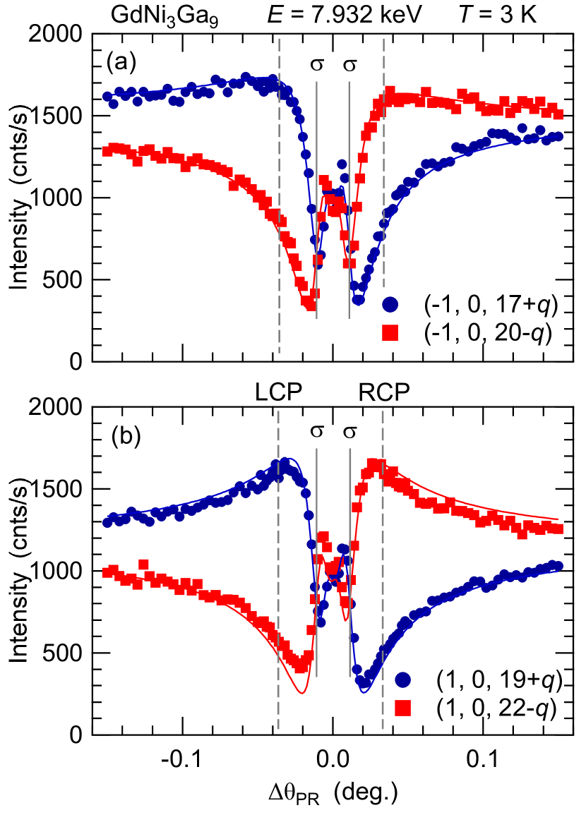
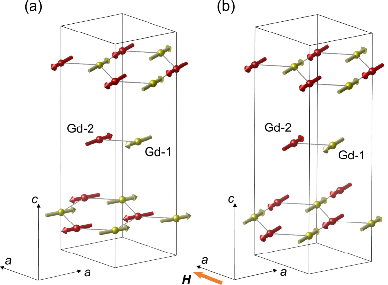
Figure 9 shows the scans, which demonstrate that this material has the helical magnetic structure in the phase. The dependences for the (1, 0, 17+) and the (1, 0, 20) peaks are opposite to each other, indicating that the magnetic structure in the phase has a chirality. The intensity of the (1, 0, 17+) peak is larger (smaller) than that of (1, 0, 20) for LCP (RCP). The same result is obtained for (1, 0, 19+) and (1, 0, 22) as well. The solid lines in Fig. 9 are the calculated curves of the scans by assuming an AFM helical magnetic structure as described below. This calculation agrees well with the scan data.
Let us analyze the magnetic structure in the phase. The magnetic moments of Gd, which are antiferromagnetically coupled in the honeycomb layer in the plane, are helically twisted along the axis with a very long pitch. There are two Gd atoms for the site of the unit cell of GdNi3Ga9 with a space group of : Gd-1 at = (0, 0, ), and Gd-2 at = (0, 0, ), where 1/6. In the present case, the magnetic moments are expected to be antiparallel to each other in the plane. There are six Gd positions in the unit cell, as indicated by the Wyckoff letter of Gd in GdNi3Ga9. The set of Gd-1 and Gd-2 are chosen to be closest to each other, and the one-to-three assignments are determined, where positions are connected by the stacking vector (2/3, 1/3, 1/3) each other. The unit vector and parallel to magnetic moments of Gd-1 and Gd-2, respectively, on the -th lattice point at = (, , ), (+2/3, +1/3, +1/3), and (+1/3, +2/3, +2/3), where , , and are integers, are expressed as
| (1) | |||
| (2) |
The and denote the unit vectors along the - and -axis, respectively, which are perpendicular to the () axis. takes values of /2, and describes a right- or left-handed helical structure. When = 178.2∘, the two spins on the same layer are perfectly antiferromagnetic for = 1.485. Note that and are different layers, and they have a relation of on the same layer. A schematic view of the magnetic structure in the phase is shown in Fig. 10(a). The twist angle of the helix is emphasized by 10 times.
The calculated dependence of the intensity for the above AFM-helical model well explains the data in Fig. 9, which were obtained at the Gd edge. The resonant scattering amplitude from the magnetic dipole order is proportional to Hannon et al. (1988); Lovesey et al. (2005), where
| (3) |
represents the magnetic dipolar structure factor at the scattering vector . Here, and denote the polarization vector of the incident and diffracted beam, respectively. In the horizontal scattering plane configuration in this experiment, the incident linear polarization is when is large. At (1, 0, 17+), is calculated to be (1, , 0) for /2. The sign is reversed at (1, 0, 20), where = (1, , 0) for /2. For (0, 0, 3n+-q), vanishes when the two Gd moments on the same layer are antiferromagnetic by setting = 178.2∘.
We use the scattering-amplitude-operator method to analyze the polarization properties of the experimental results Lov . We consider a matrix , consisting of four elements of the scattering amplitudes for the polarization arrangements , , , and :
As shown in Appendix B in Ref. Matsumura et al. (2017), the scattering cross section (d/d) is expressed as
| (4) |
where = 0 in the present geometry of the phase retarder. By using the scattering amplitude matrix = , (/, /) is calcurated to be (0.574, 0.562) and (0.574, 0.562) for (1, 0, 17 + ) and (1, 0, 20 - ), respectively, where . The solid lines in Fig. 9 are the calculated curves using the above-mentioned magnetic structure model and agree with the experimental data.
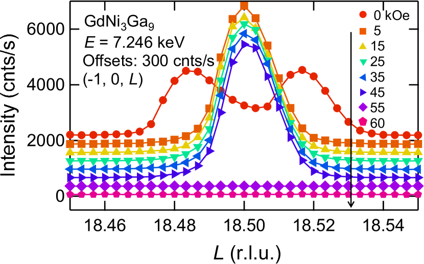
The AFM-helical order soon changes to an AFM order by applying a magnetic field in the plane, where the AFM moments are aligned perpendicular to the field. Figure 11 shows the magnetic field dependence of the (1, 0, ) peak profile at the lowest temperature of 3 K. With increasing magnetic field, the AFM chiral helix peak soon moves to the commensurate position at (0, 0, 1.5) in a weak magnetic field of 3 kOe above which the phase is realized. The propagation vector (0, 0, 1.5) corresponds to the antiferromagnetic alignment of adjacent Gd honeycomb layers. The -value sharply changes from 1.485 to 1.5 with increasing field, and it is hard to observe the soliton lattice Zheludev et al. (1997). When a magnetic field is further increased, the transition from the to phases occurs at 45 kOe. Although the magnetic Bragg peak was searched along the (1, 0, ) line and several other conditions in the phase, the peak could not be found. This result suggests that the -vector may have changed from (0, 0, 1.5) to (0, 0, 0). The details of the phase are still unknown. From the results of the magnetization measurements, however, the curve suggests an AFM component remains. ErNi3Ga9 and DyNi3Ga9 having the same crystal structure as this material also exhibit AFM order Tsukagoshi et al. (2022); Ninomiya et al. (2018).
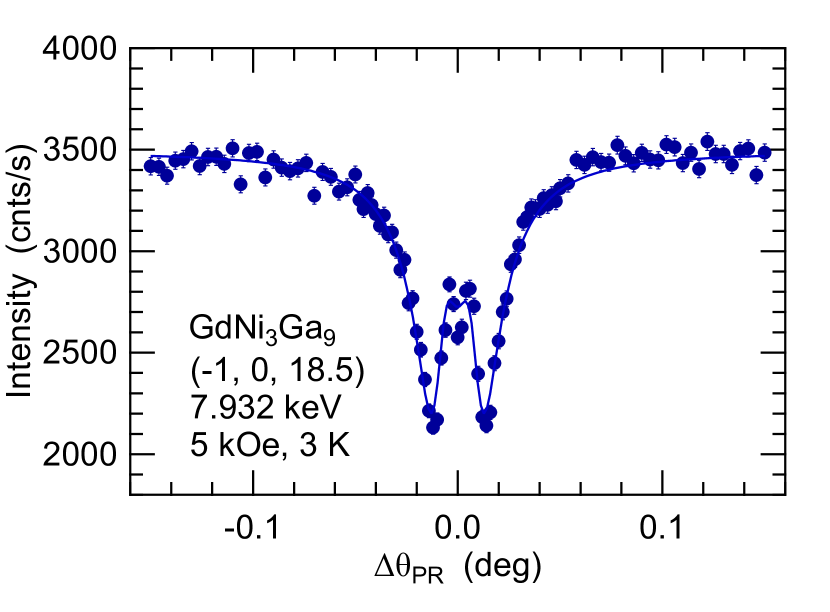
Figure 12 shows the scan at (1, 0, 18.5), where (0, 0, 1.5), in the phase. The shape is different from the one in the phase with = 1.485, and symmetrical around = 0, because of the loss of the chirality. The solid line is a calculated one as in Fig. 9 for a magnetic structure as shown in Fig. 10(b), where the antiferromagnetically-aligned magnetic moments of Gd orient perpendicular to the magnetic field direction in the Gd honeycomb plane. The experimental data are in good agreement with the calculation.
IV Conclusion
We have performed the magnetization and specific heat measurements, and resonant x-ray diffraction experiments to investigate the helical magnetic structure of GdNi3Ga9 with the Sohncke space group , where a chiral magnetic structure is allowed because of lacks both of inversion and mirror symmetries. This material exhibits an AFM helical order at 19.5K, where a cusp in the magnetic susceptibility, which is a character of a chiral helix, is observed. In this state, the magnetic moments of Gd twist 178.2∘ per a Gd honeycomb layer along the helical axis with (0, 0, 1.485), where the period of the helix is the length of 66.7 unit cells, and antiferromagnetically align in the plane. We confirmed that the magnetic Bragg peaks with (0, 0, 1.485) exhibit opposite response to the RCP and LCP incident x-rays, indicating that the AFM helix consists of a single sense of rotation. With increasing magnetic field, the AFM helical state changes to an antiferromagnetic phase with (0, 0, 1.5) in of 3 kOe. This corresponds to a magnetic structure where the magnetic moments between the adjacent Gd honeycomb layers are antiferromagnetically aligned perpendicular to the axis.
GdNi3Ga9 and YbNi3Al9 have the same crystal structure and antiferromagnetic and ferromagnetic spiral magnetic structures, respectively. In the future, research that compares these materials is desired.
Acknowledgments
This study was supported by the JSPS KAKENHI Grant Numbers JP18K03539, JP20H01854, JP21K03467, JP21K13879, JP23H04870. The synchrotron radiation experiments at KEK were performed with the approval of the Photon Factory Program Advisory Committee (Proposal No. 2022G520).
References
- Mühlbauer et al. (2009) S. Mühlbauer, B. Binz, F. Jonietz, C. Pfleiderer, A. Rosch, A. Neubauer, R. Georgii, and P. Böni, Science 323, 915 (2009).
- Togawa et al. (2012) Y. Togawa, T. Koyama, K. Takayanagi, S. Mori, Y. Kousaka, J. Akimitsu, S. Nishihara, K. Inoue, A. Ovchinnikov, and J.-i. Kishine, Phys. Rev. Lett. 108, 107202 (2012).
- Togawa et al. (2016) Y. Togawa, Y. Kousaka, K. Inoue, and J.-i. Kishine, J. Phys. Soc. Jpn. 85, 112001 (2016).
- Momma and Izumi (2011) K. Momma and F. Izumi, Journal of applied crystallography 44, 1272 (2011).
- Ohara et al. (2011) S. Ohara, T. Yamashita, Y. Mori, and I. Sakamoto, J. Phys.: Conf. Ser. 273, 012048 (2011).
- Matsumura et al. (2017) T. Matsumura, Y. Kita, K. Kubo, Y. Yoshikawa, S. Michimura, T. Inami, Y. Kousaka, K. Inoue, and S. Ohara, J. Phys. Soc. Jpn. 86, 124702 (2017).
- Ninomiya et al. (2017) H. Ninomiya, Y. Matsumoto, S. Nakamura, Y. Kono, S. Kittaka, T. Sakakibara, K. Inoue, and S. Ohara, J. Phys. Soc. Jpn. 86, 124704 (2017).
- Ishii et al. (2018) I. Ishii, K. Takezawa, T. Mizuno, S. Kamikawa, H. Ninomiya, Y. Matsumoto, S. Ohara, K. Mitsumoto, and T. Suzuki, J. Phys. Soc. Jpn. 87, 013602 (2018).
- Ishii et al. (2019) I. Ishii, K. Takezawa, T. Mizuno, S. Kumano, T. Suzuki, H. Ninomiya, K. Mitsumoto, K. Umeo, S. Nakamura, and S. Ohara, Phys. Rev. B 99, 075156 (2019).
- Tsukagoshi et al. (2022) M. Tsukagoshi, T. Matsumura, S. Michimura, T. Inami, and S. Ohara, Phys. Rev. B 105, 014428 (2022).
- Sato et al. (2022) Y. J. Sato, H. Manako, Y. Homma, D. Li, R. Okazaki, and D. Aoki, Physical Review Materials 6, 104412 (2022).
- Kakihana et al. (2018) M. Kakihana, D. Aoki, A. Nakamura, F. Honda, M. Nakashima, Y. Amako, S. Nakamura, T. Sakakibara, M. Hedo, T. Nakama, et al., J. Phys. Soc. Jpn. 87, 023701 (2018).
- Kakihana et al. (2019) M. Kakihana, D. Aoki, A. Nakamura, F. Honda, M. Nakashima, Y. Amako, T. Takeuchi, H. Harima, M. Hedo, T. Nakama, et al., J. Phys. Soc. Jpn. 88, 094705 (2019).
- Tabata et al. (2019) C. Tabata, T. Matsumura, H. Nakao, S. Michimura, M. Kakihana, T. Inami, K. Kaneko, M. Hedo, T. Nakama, and Y. Ōnuki, J. Phys. Soc. Jpn. 88, 093704 (2019).
- Sakakibara et al. (2019) T. Sakakibara, S. Nakamura, S. Kittaka, M. Kakihana, M. Hedo, T. Nakama, and Y. Ōnuki, J. Phys. Soc. Jpn. 88, 093701 (2019).
- Topertser et al. (2019) V. Topertser, R.-I. Martyniak, N. Muts, Y. Tokaychuk, and R. Gladyshevskii, Chem. Met. Alloys 12, 21 (2019).
- Nakamura et al. (2020) S. Nakamura, J. Inukai, T. Asaka, J.-i. Yamaura, and S. Ohara, J. Phys. Soc. Jpn. 89, 104005 (2020).
- Ishida et al. (1985) M. Ishida, Y. Endoh, S. Mitsuda, Y. Ishikawa, and M. Tanaka, J. Phys. Soc. Jpn. 54, 2975 (1985).
- Yamasaki et al. (2007) Y. Yamasaki, H. Sagayama, T. Goto, M. Matsuura, K. Hirota, T. Arima, and Y. Tokura, Phys. Rev. Lett. 98, 147204 (2007).
- Sutter et al. (1997) C. Sutter, G. Grübel, C. Vettier, F. De Bergevin, A. Stunault, D. Gibbs, and C. Giles, Phys. Rev. B 55, 954 (1997).
- Fabrizi et al. (2009) F. Fabrizi, H. C. Walker, L. Paolasini, F. de Bergevin, A. T. Boothroyd, D. Prabhakaran, and D. F. McMorrow, Phys. Rev. Lett. 102, 237205 (2009).
- Sagayama et al. (2010) H. Sagayama, N. Abe, K. Taniguchi, T.-h. Arima, Y. Yamasaki, D. Okuyama, Y. Tokura, S. Sakai, T. Morita, T. Komesu, et al., J. Phys. Soc. Jpn. 79, 043711 (2010).
- Kishine et al. (2005) J.-i. Kishine, K. Inoue, and Y. Yoshida, Progress of Theoretical Physics Supplement 159, 82 (2005).
- Kousaka et al. (2007) Y. Kousaka, S.-i. Yano, J.-i. Kishine, Y. Yoshida, K. Inoue, K. Kikuchi, and J. Akimitsu, J. Phys. Soc. Jpn. 76, 123709 (2007).
- Hidaka et al. (2020) H. Hidaka, K. Mizuuchi, E. Hayasaka, T. Yanagisawa, J. Ohara, and H. Amitsuka, Phys. Rev. B 102, 174408 (2020).
- Bouvier et al. (1991) M. Bouvier, P. Lethuillier, and D. Schmitt, Phys. Rev. B 43, 13137 (1991).
- Blanco et al. (1991) J. A. Blanco, D. Gignoux, and D. Schmitt, Phys. Rev. B 43, 13145 (1991).
- Hannon et al. (1988) J. P. Hannon, G. T. Trammell, M. Blume, and D. Gibbs, Phys. Rev. Lett. 61, 1245 (1988).
- Lovesey et al. (2005) S. W. Lovesey, E. Balcar, K. Knight, and J. F. Rodríguez, Physics Reports 411, 233 (2005).
- (30) S. W. Lovesey and S. P. Collins, X-ray Scattering and Absorption by Magnetic Materials (Oxford University Press, New York, 1996).
- Zheludev et al. (1997) A. Zheludev, S. Maslov, G. Shirane, Y. Sasago, N. Koide, and K. Uchinokura, Physical review letters 78, 4857 (1997).
- Ninomiya et al. (2018) H. Ninomiya, T. Sato, Y. Matsumoto, T. Moyoshi, A. Nakao, K. Ohishi, Y. Kousaka, J. Akimitsu, K. Inoue, and S. Ohara, Physica B: Condensed Matter 536, 392 (2018).