Compact Chirped Fiber Bragg Gratings for Single-Photon Generation from Quantum Dots
E-mail: vikas.remesh@uibk.ac.at)
Abstract
A scalable source of single photons is a key constituent of an efficient quantum photonic architecture. To realize this, it is beneficial to have an ensemble of quantum emitters that can be collectively excited with high efficiency. Semiconductor quantum dots hold great potential in this context, due to their excellent photophysical properties. Spectral variability of quantum dots is commonly regarded as a drawback introduced by the fabrication method. However, this is beneficial to realize a frequency-multiplexed single-photon platform. Chirped pulse excitation, relying on the so-called adiabatic rapid passage, is the most efficient scheme to excite a quantum dot ensemble due to its immunity to individual quantum dot parameters. Yet, the existing methods of generating chirped laser pulses to excite a quantum emitter are bulky, lossy, and mechanically unstable, which severely hampers the prospects of a quantum dot photon source. Here, we present a compact, robust, and high-efficiency alternative for chirped pulse excitation of solid-state quantum emitters. Our simple plug-and-play module consists of chirped fiber Bragg gratings (CFBGs), fabricated via femtosecond inscription, to provide high values of dispersion in the near-infrared spectral range, where the quantum dots emit. We characterize and benchmark the performance of our method via chirped excitation of a GaAs quantum dot, establishing high-fidelity single-photon generation. Our highly versatile chirping module coupled to a photon source is a significant milestone toward realizing practical quantum photonic devices.
Introduction
Future quantum communication architectures rely on bright and efficient sources of high-purity single-photons and entangled photon pairs with superior photostability and scalability. Semiconductor quantum dots are the most important candidates for this role, due to their high brightness [1, 2], high degrees of entanglement [3, 4], low multiphoton rate [5] and near-deterministic operating nature. An important feature of quantum dots is the possibility to control the emission wavelength of an ensemble by properly choosing materials, growth methods, and fabrication parameters. Further post-growth tuning is offered by electric [6], magnetic[7], optical [8] or strain field tuning [9]. However, these methods increase the complexity of the photon source. The natural spread in the dots’ physical properties like size, composition, and strain is commonly perceived as an obstacle to achieving scalable quantum hardware. However, the resulting distribution in emission wavelengths offers a convenient way to produce frequency-multiplexed single-photons and entangled photon pairs. Therefore, it is important to develop a simple, efficient, and long-term stable optical excitation method that delivers high-quality photons from the source.
Several resonant and off-resonant optical excitation schemes have been developed to generate single-photons or entangled photon pairs from quantum dots [10, 11, 12, 13, 14, 15, 16, 17]. In particular, chirped excitation relying on Adiabatic Rapid Passage (ARP) is a robust scheme for quantum dot excitation as demonstrated before [18, 19, 20, 21, 22, 23]. The ARP excitation is immune to fluctuations in the laser power and spectral properties of quantum dots, which facilitates a collective driving to produce single-photons [24, 23] or entangled photon pairs [25]. It is also known that in ARP, the excitation efficiency depends on the sign of the chirp, i.e., positive chirp achieves near-unity excitation efficiency, while for negative chirp, preparation efficiencies are lower due to phonon influences [26].
In most of the practical implementations, chirped pulses are prepared by introducing the Group Delay Dispersion (GDD) in the laser spectral phase [27]. Examples include diffraction-grating stretchers [28, 29, 30, 31, 22, 32, 23] and programmable spatial light modulators (SLM) [33, 34, 35, 21, 15]. While the SLM-based techniques are user-friendly and enable arbitrary spectral phase manipulation, they are pixellated devices with limited resolution and response times and bear phase wrapping issues. Diffraction-grating stretchers, on the other hand, can be designed to provide extremely high dispersion [36]. Yet both of these approaches are bulky, beam-distorting, lossy, and inherit spatiotemporal coupling artifacts and higher-order dispersions [37, 38]. To compensate for optical aberrations and higher-order dispersions, one requires rigorous alignment procedures which restrict practical applications. For instance, to accomplish a robust, and optomechanically stable single-mode laser coupling to a quantum dot source, we must ensure a fast and effective approach without spatiotemporal artifacts and aberrations.
In this Letter, we demonstrate a simple, compact, plug-and-play, and alignment-free approach for chirped pulse excitation of quantum emitters, which circumvents the obstacles in other existing methods. Our design is based on a chirped fiber Bragg gratings (CFBG), fabricated via a femtosecond phase mask inscription, to provide tailored values of GDD around with large spectral bandwidth and high efficiency. Our results pave the way for realizing compact solid-state single-photon sources in an advanced quantum photonic architecture.
Chirped fiber Bragg gratings for quantum dot excitation
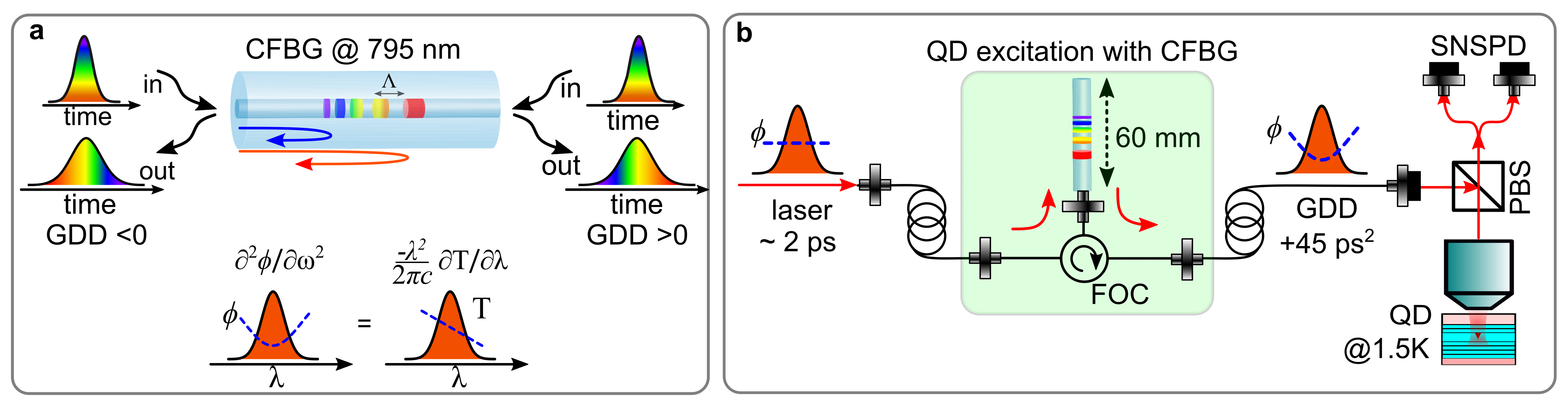
A fiber Bragg grating consists of an optical fiber with a periodic variation of the refractive index in the core, providing a narrowband in-fiber reflection. The reflecting wavelength depends on the grating period and the effective refractive index of the guided mode in the fiber core. In a CFBG, however, the grating period is not constant but is varied along the propagation axis . This results in the reflection of different wavelengths at different spatial positions of propagation:
| (1) |
Hence, different parts of the laser spectrum that is reflected at the CFBG acquire different time delays, i.e., the laser pulse gets chirped in time. In Figure 1a we summarize the working principle of a CFBG (see also SI). Note that by adjusting the grating period along the propagation axis, the dispersive response of the CFBG is defined: a linear variation of the grating period introduces second-order dispersion, a quadratic variation introduces third-order dispersion, and so on [39]. Initially proposed for dispersion cancellation in optical telecommunication waveguides [40, 41], CFBGs have been employed for chirped pulse amplification [42, 43], pulse shaping [44, 45, 46, 39] and high time resolution spectroscopy [47, 48], among many others. Yet despite the progress in this technology, CFBGs have not been explored for chirped excitation of quantum emitters around .
For single-photon generation from quantum dots, CFBGs have a huge potential, as illustrated in Figure 1b. To start with, CFBGs are an important breakthrough towards realizing a direct fiber-coupled, alignment-free, high-efficiency, and scalable quantum dot photon source [49, 50, 51, 52, 53]. They can be tailored to provide arbitrary values of GDD, with a spectral bandwidth of or more, coincident with the typical spectral variability of a quantum dot ensemble [54, 55]. More importantly, CFBG-based dispersion is robust against mechanical instabilities and vibrations. As it does not rely on angular dispersion, CFBGs eliminate optical aberrations and spatiotemporal couplings, to provide excellent single-mode coupling to the quantum dot source. Furthermore, a diffraction-grating stretcher [29, 30, 56] designed for chirp is bulky (several meters long, see SI for details). In comparison, a CFBG for the same GDD is only a few millimeters long. The versatility of a CFBG is that it allows inverting the GDD by switching the propagation direction, while in a grating stretcher, adding the option to invert the GDD increases the footprint of the setup even further. Interestingly, with CFBGs we can realize additive combinations [45], i.e., one can cascade several CFBGs to obtain a range of GDDs, without increasing the complexity of the setup.
Experimental implementation
To inscribe the CFBGs we employ a phase mask scanning technique using femtosecond laser pulses [57] with wavelength, pulse duration at repetition rate (Spectra-Physics Spitfire Ace). The fiber core refractive index modification is induced by multiphoton absorption of the incident laser irradiation. The non-periodic modulation of the refractive index modification is generated by a phase mask (i.e., a transmission grating, manufactured in-house at the University of Jena), which defines the resulting distribution of the grating period along the fiber axis. To spectrally characterize the fabricated CFBGs in reflection and transmission, we use linearly polarized light from a supercontinuum source (NKT, SuperK EXR-15) and an optical spectrum analyzer (Yokogawa, OSA AQ6375). A fiber-optic circulator (PMOptics) helps extract the reflected signal of the CFBG. From the transmitted signal, we determine the reflection strength as well as any broadband losses introduced by the inscription process. For dispersion characterization of the CFBG, we rely on a time-of-arrival technique.
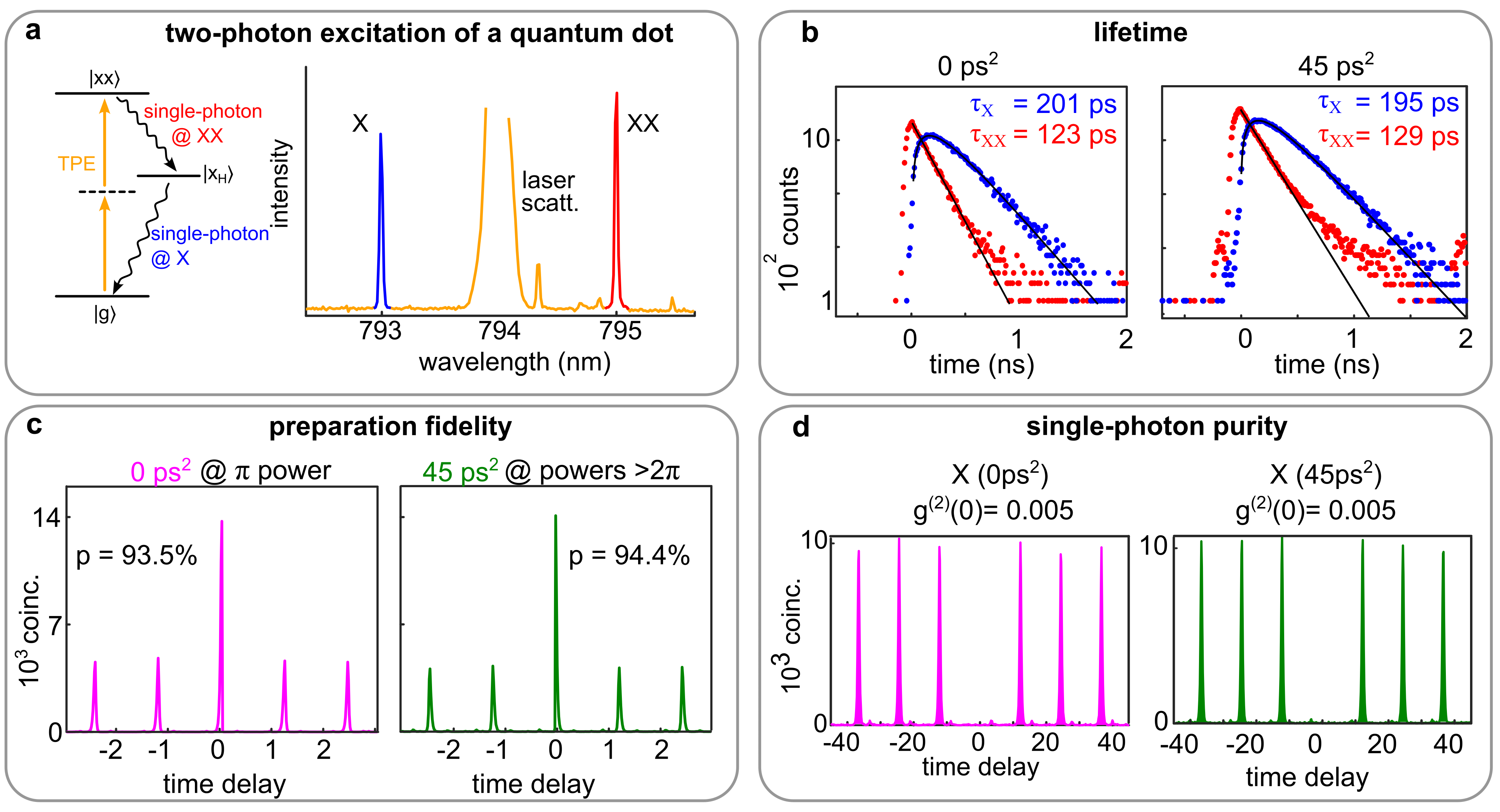
For quantum dot excitation, we tune the laser source to , such that a two-photon resonant excitation to the biexciton state is enabled [3, 12, 22, 23]. The laser beam is directly coupled to a CFBG and the resulting, dispersed pulses are directed to the quantum dot sample (see SI and Ref. [23] for details) mounted in a closed-cycle cryostat with a base temperature of (ICEOxford). The quantum dot emission is collected via the same path, and exciton (X) and biexciton (XX) emission photons are filtered using notch filters (BNF-805-OD3, FWHM , Optigrate) and directed to superconducting nanowire single-photon detectors (SNSPD, Eos, Single Quantum). In the setup we employ cross-polarization filtering for efficient laser scattering rejection.
Results
.1 CFBG results
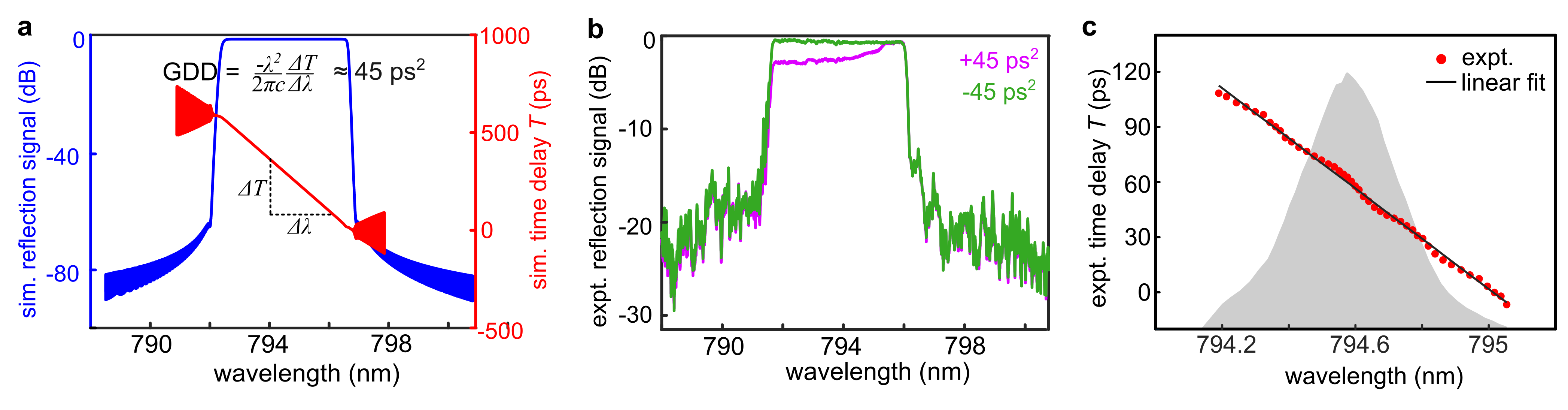
For the experiments described in this paper, we realize a set of three CFBGs with different GDDs (, , and respectively). The phase masks employed have their center period around , resulting in CFBG center period of , which corresponds to a second-order reflection at (see SI for details). To calculate the required linear period variation, i.e., the chirp rate of the CFBG, we use the transfer matrix algorithm as described in Ref. [58]. The achievable bandwidth of the CFBG is limited by its maximum length, which is in our setup. In Figure 2a we present the simulated reflection spectrum (blue curve) and the wavelength-dependent time delay (, red curve) of the CFBG. From the slope of the red curve, we compute the dispersion parameter , from which we obtain the GDD (see SI for details).
In Figure 2b we present the measured reflection spectra for the CFBG (magenta and green curves respectively). We observe a reflectivity from to , showing an excellent agreement with the simulation in Figure 2a. The average sideband suppression is . Note that, for the direction, lower wavelengths experience more losses due to the cladding mode coupling [57] which arises from the chosen inscription pattern.
We attribute a nominal 10% loss to the absorption and scattering of the guided light in the grating structure. Two other major factors for the loss are the circulator and the connector losses, due to the mismatch of different core diameters (for more details see SI). The latter can be avoided by directly splicing the CFBG to the circulator. Losses due to the splicing of the bare fiber with the inscribed CFBG and connectorized fibers are negligible.
To characterize the GDD response of CFBGs we perform a time-of-arrival measurement which directly measures the wavelength-dependent time delay (see SI for details). In Figure 2c we display the result for + CFBG. Based on the variation of the fitted peak wavelengths with respect to their arrival times recorded with the SNSPD, we obtain a , which corresponds to , showing an excellent match with the simulation in Figure 2a.
.2 QD experiment results
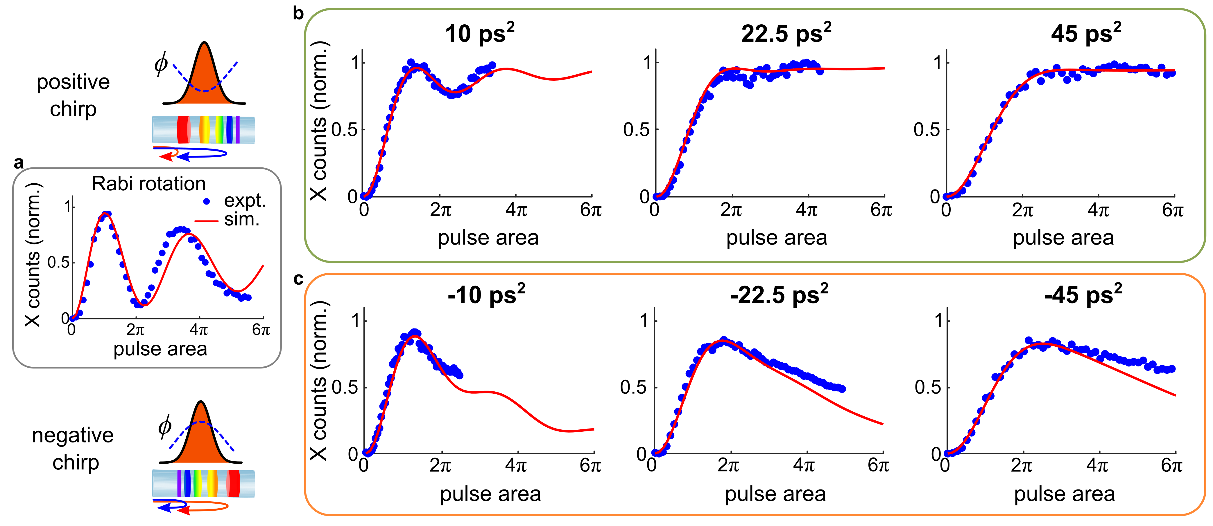
We then proceed to investigate the single-photon generation from quantum dots. We select a quantum dot resonant within the CFBG bandwidth and characterize it under two-photon excitation (see SI for details). The exciton (X) wavelength is found to be and the biexciton (XX) wavelength is . To confirm the resonance condition, we perform a Rabi rotation experiment upon the sweep of the laser power, while recording the corresponding emission spectra. The integrated intensities corresponding to the X emission (for simplicity, XX photon counts are not displayed) are displayed in Figure 3a, clearly demonstrating the Rabi oscillations.
We then investigate the utility of CFBG for chirped excitation of the quantum dot i.e., ARP experiment. To this end, we perform the laser power sweep experiments on the same quantum dot using the three CFBGs (, and respectively). The results are displayed in Figure 3b, with respective chirp values labeled alongside. At , we observe that the oscillatory behavior in the recorded X photon counts diminishes. The same experiment at shows that the Rabi oscillations have nearly vanished, and a plateau is attained for higher pulse power, signifying that the process is closer to ARP condition. Finally, with the CFBG, we observe a clear plateau in the X photon counts for pulse powers >2, demonstrating that the ARP process is induced, confirming the previous observations [19, 21, 22, 32, 24, 23].
To further validate the robustness of ARP excitation, we investigate the excited state preparation efficiency under both conditions via a biexciton-to-exciton cross-correlation experiment, as in Ref. [59]. We observe that the preparation efficiencies are 93.5% in the case of Rabi rotation (largest value, i.e., at power) and >94.4% for ARP condition (for all powers >), in agreement with the previous reports [23, 4] on a similar quantum dot system (for details see SI). Note that, the preparation efficiency under Rabi rotation is extremely sensitive to the pulse power [23], while under chirped pulse excitation, the preparation efficiency is insensitive to power variations.
To demonstrate the versatility of CFBGs for chirped pulse excitation, we switch the pulse propagation direction (i.e., to obtain a negatively chirped pulse) and repeat the experiments, and the results are displayed in Figure 3c. We observe that, as expected [19, 60], the quantum dot excitation efficiency does not reach unity, and the X photon counts drop to 30% at higher pulse areas, in agreement with earlier experimental observations [21, 22]. This validates the fact, for chirped pulse excitation of quantum dots, the sign of the chirp determines the efficiency, due to phonon influences [19, 60].
Finally, we also confirm the nature of the photon emission from the quantum dot under the resonant Rabi and the chirped excitations. To this end, we perform Hanbury-Brown and Twiss () measurements and observe that the computed (see SI), validating the single-photon nature of the emission.
Conclusions
To summarize, we demonstrated a systematic study of designing and fabricating compact, plug-and-play chirped fiber Bragg gratings tailored to a GaAs quantum dot resonance. Our high-efficiency femtosecond phase mask inscription method of CFBGs enabled precise control over the temporal characteristics of the excitation pulses. We established the versatility of the CFBGs by performing the two-photon chirped pulse excitation of a quantum dot under positive and negative chirps. Under positively chirped excitation, we observed a high-efficiency generation of single photons at exciton and biexciton energies, relying on the adiabatic rapid passage, while for negative chirps, we observed lower efficiency state preparation, in accordance with previous reports. In comparison with the prevailing methods for chirped pulse excitation, our method is robust, highly efficient, and optomechanically stable. Our results are in excellent agreement with theoretical simulations. In conclusion, these open an exciting avenue toward realizing an all-fiber-coupled, and alignment-free solid-state source of frequency-multiplexed single and entangled photon pairs. The versatility of CFBGs also allows for the development of efficient and compact pulse-shaping methods tailored to control various quantum states in any solid-state platform.
Acknowledgements
The authors gratefully acknowledge insightful discussions with Timothy Imogore (Jena), Thorsten Goebel (Jena), Dmitry Pestov (IPG Photonics), Ron Stepanek (Meadowlark Optics), and Thomas Niedereichholz (Hamamatsu). VR, RS, FK, YK and GW acknowledge financial support through the Austrian Science Fund FWF projects TAI-556N (DarkEneT), W1259 (DK-ALM Atoms, Light, and Molecules), FG5, and I4380 (AEQuDot). TKB and DER acknowledge financial support from the German Research Foundation DFG through project 428026575 (AEQuDot). AR and SFCdS acknowledge the FWF projects FG 5, P30459, I4320, the Linz Institute of Technology (LIT), the European Union’s Horizon 2020 research, and innovation program under Grant Agreement Nos. 899814 (Qurope), 871130 (ASCENT+), and the QuantERA II Program (project QD-E-QKD, FFG Grant No. 891366). RGK acknowledges financial support from the German Federal Ministry of Education and Research through project 13N16028 (MHLASQU) and the German Research Foundation DFG (455425131, OH-SUPER). DR acknowledges financial support from the German Research Foundation DFG through project 448663633 (Fs2CVBG).
Author contributions
VR, GW and SN conceived and supervised the project. RGK, DR and MPS designed and fabricated the chirped fiber Bragg gratings. SFCdS and AR provided the quantum dot sample. RS, FK, YK, RGK, and VR built the setups and performed the experiments. VR and RGK wrote the first draft of the manuscript with input from other authors. FK, YK and RGK performed the data analysis and numerical simulations. All the authors discussed the results and were involved in writing the manuscript.
I Supplementary Information
I.1 Chirped laser pulses
Chirped pulses possess time-varying frequency. In the frequency domain, this is described by
| (2) |
where is the amplitude of the Gaussian frequency envelope centered at with a frequency bandwidth of . The constant describes the group delay dispersion, GDD, or linear chirp.
By definition, the GDD is the second derivative of the spectral phase with respect to the angular frequency , or the first derivative of group delay () with respect to frequency. i.e.,
| (3) |
In a CFBG, the time delay of wavelengths is varied by controlling the Bragg reflection resonances at various positions along the propagation direction in the fiber core. Converting everything to the wavelength domain, we can relate the dispersion parameter (specified as ) to GDD (specified as ) through
| (4) |
It is now clear that a positive GDD implies a shorter time delay for the red part of the laser spectrum and vice versa for negative GDD.
I.2 CFBG details
The CFBGs employed in this work are fabricated via femtosecond phase mask inscription technique [61, 57] The dispersion parameter can be determined from the time delay between the reflections of various wavelength components as
| (5) |
In the CFBG with the grating length , the effective refractive index of the guided light and as the speed of light in vacuum, the delay time is given by
| (6) |
Note that each wavelength component travels twice the distance within the CFBG, as it functions in reflection. Then
| (7) |
which leads to
| (8) |
and in terms of GDD, this will be
| (9) |
which provides an estimate for the required grating length to provide a given GDD.
In Figure 4 we present the results of the further reflectivity measurements on CFBGs. Note that due to the chosen inscription pattern, for the positive GDD input side, lower wavelengths experience more losses due to the cladding mode coupling [57].

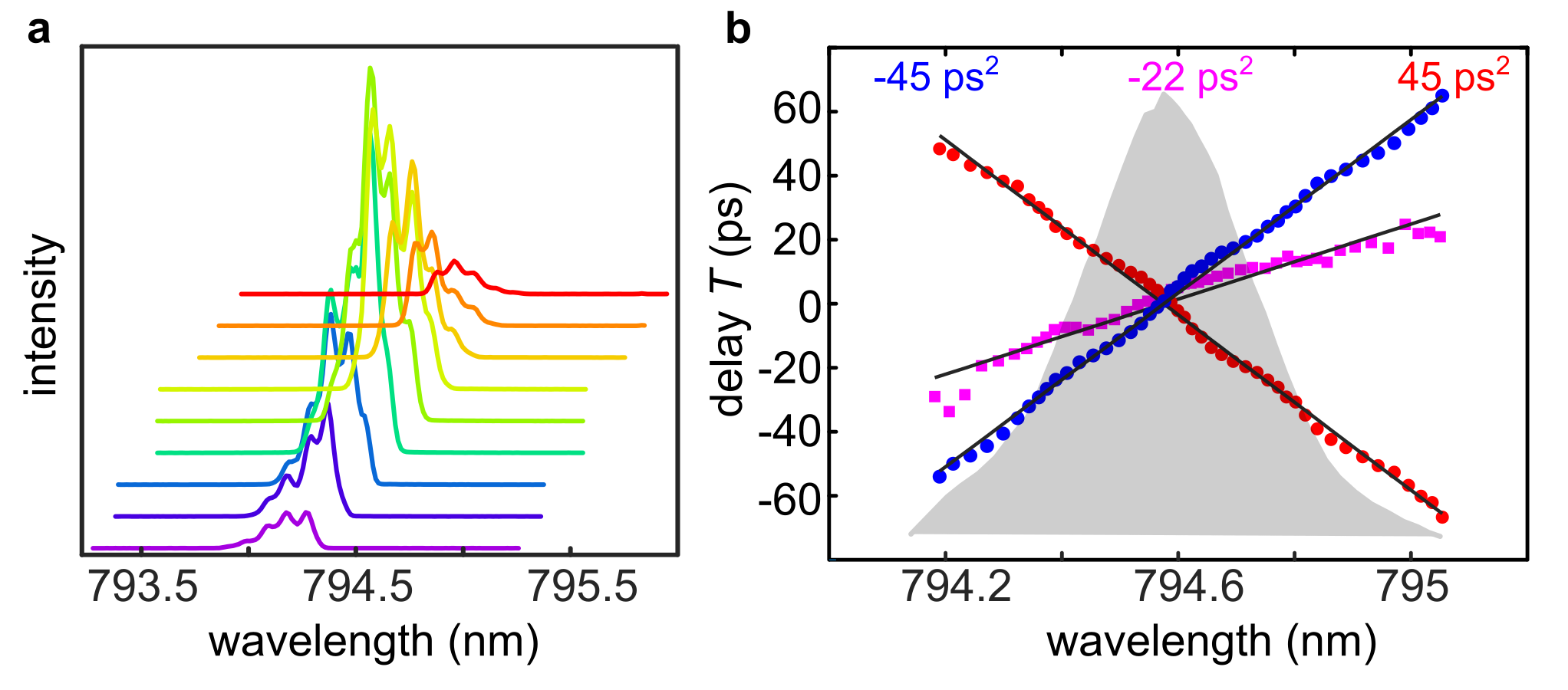
In the time-of-arrival (ToA) method of characterizing dispersion, we select several narrow spectra from the reference laser spectrum using a 4 pulse shaper equipped with a motorized slit on its Fourier plane and propagate through the CFBG. The resulting, dispersed laser pulses are simultaneously recorded with a spectrometer and SNSPD (time resolution ) using 10:90 fiber beam-splitter. While with the spectrometer we obtain the wavelength component, with the SNSPD we record its arrival time with respect to the reference laser spectrum. To extract the wavelength component precisely, we employ a Gaussian fit to the measured laser spectra, to obtain a plot of time delay as a function of central wavelength. The slope extracted from this plot provides the dispersion parameter , from which the GDD can be obtained. In Figure 5 we display the result of ToA measurement for and .
In Table 1 we summarize the parameters of all the CFBGs and their measured performance parameters.
| CFBG | 45 | 22 | 10 |
| GDD () | |||
| Chirp rate () | |||
| Length () | |||
| Center wavelength () | |||
| FWHM () | |||
| D1λ () | () | – | |
| GDD () | () | – |
I.3 Multiple order CFBG resonances
The change of the refractive index during the CFBG inscription process is a result of multiphoton absorption in the fiber core due to the femtosecond laser irradiation [57]. Due to the nature of this process, the underlying refractive index change is nonlinear, i.e., the modulation of the refractive index is non-sinusoidal. The pattern along the propagation axis can be expressed as a sum of its Fourier terms :
| (10) |
with the Fourier order , the nominal grating period and the grating chirp described by . Consequently, the CFBG reflects at multiple wavelengths, corresponding to each of the Fourier terms,
| (11) |
Therefore, a CFBG with a center period of will reflect in first order at = , in second order at = , in third order at = and so on.
I.4 QD simulations
Simulations of the pulse area-dependent biexciton population (see Figure 3 in the main manuscript) are performed using a numerically complete path-integral method described in detail in Ref. [62]. For this we set up a Hamiltonian consisting of the quantum dot system , the coupling to the laser field as well as the coupling to phonons
| (12) |
We model the quantum dot as a four-level system consisting of the ground state two exciton states of orthogonal polarisation, and , and the biexciton state . The ground state energy is set to zero, while the two exciton states are assumed to be of the same energy , i.e., no fine structure splitting is present. The biexciton state has a binding energy such that .
| (13) |
Coupling to the laser field is modeled with a classical laser field
| (14) |
where is the Fourier transform of Equation 2. In Figure 3 we scale the x-axis of the simulation to be proportional to , i.e., the pulse power.
Finally, we consider coupling to longitudinal-acoustic (LA) phonons via the deformation potential coupling. Here, () annihilates (creates) a phonon of mode with energy . We consider the typical pure-dephasing type coupling in the standard Hamiltonian
| (15) |
coupling each mode to the quantum dot state , where and is the number of excitations, i.e., 1 for and and 2 for . The coupling constant and the material parameters are taken to be the same as in Ref. [63] and further simulation parameters are shown in Table 2.
| frequency bandwidth | 1.410 | |
|---|---|---|
| Binding energy | 4 meV | |
| QD size | 5 nm | |
| temperature | 1.5 K |
I.5 Comparison of various chirping methods
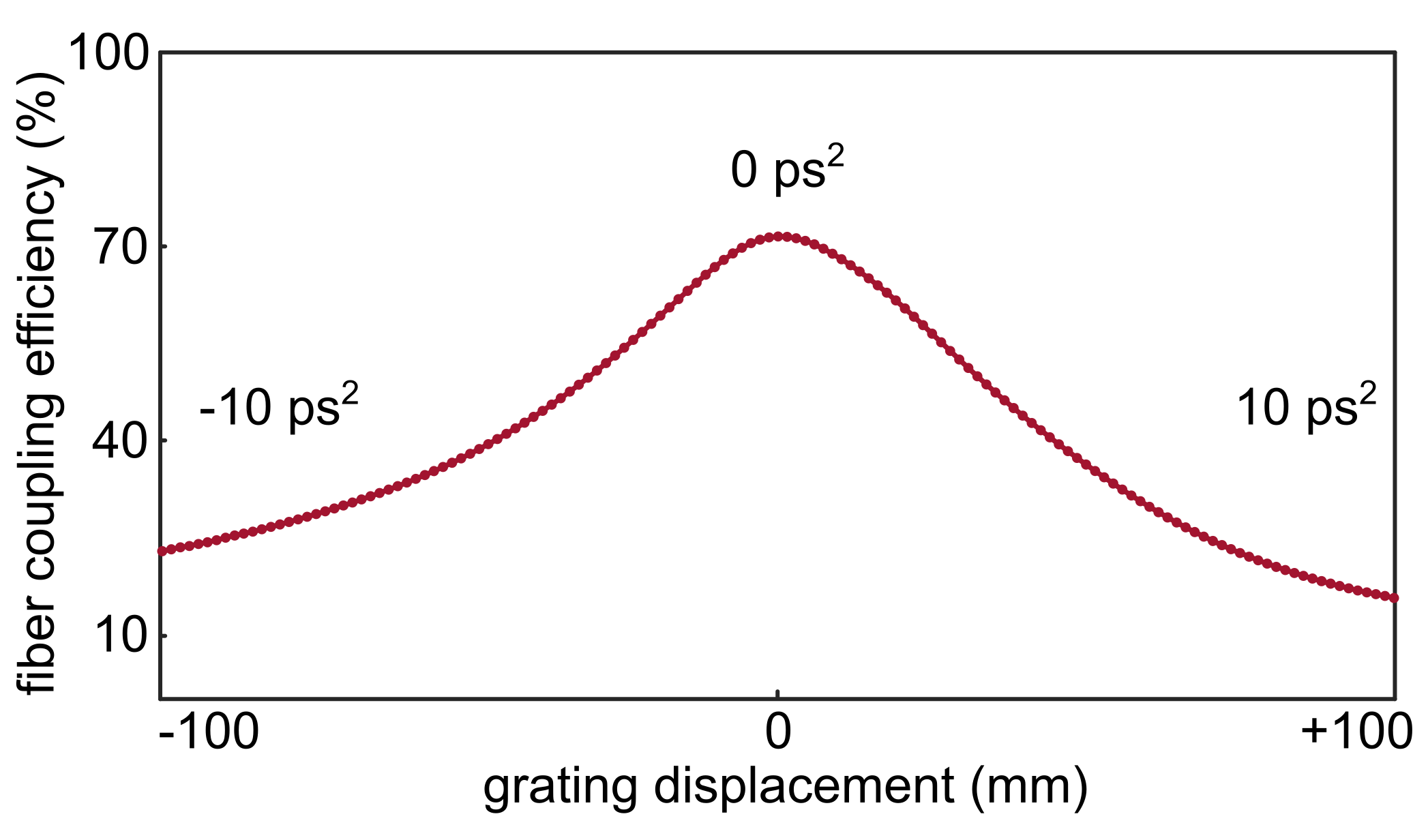
In this section, we compare various chirping methods. Grating stretcher: For imparting we designed and constructed a grating stretcher in folded geometry (details in Ref.[23]). Here grating period at and distance from the lens () with angle of incidence () and grating efficiency is 70%. Note that in the grating stretcher, the inherited third and fourth-order dispersions can be compensated in principle, yet, it increases the experimental complexity. The overall efficiency strongly depends on the efficiency of a single grating, i.e., . Additionally, optical aberrations also contribute to lower fiber-coupling efficiencies. To illustrate this, in Figure 6 we describe the variation in single-mode fiber coupling efficiency as a function of grating position in our grating stretcher, as obtained by ray-tracing simulations.
In an SLM-equipped 4 shapers, the difference from the grating stretcher is that a programmable SLM is mounted at the Fourier plane. The straightforward improvement is the deterministic, adaptive, and programmable spectral phase manipulation, including higher-order components. Imparting negative dispersion does not enhance the footprint, as in grating stretchers. There are two classes of SLMs: dual-mask, transmissive SLMs [21, 35, 24], and two-dimensional, reflective SLMs [64]. The transmissive SLMs operate by controlling the phase between frequency components, depending on the voltage applied, in a 4 shaper [27]. They suffer from transmission losses of liquid crystal layers. To perform simultaneous phase-amplitude shaping, one requires dual mask SLMs, which when operated in a folded, double-pass configuration, leads to a doubling of the transmission loss per liquid crystal layer. Therefore, the total efficiency is . The reflective SLM also operates in a 4 shaper, however, it functions based on diffractive pulse shaping [64]. Here, the total efficiency is , where the first two terms refer to the reflection and diffraction efficiencies respectively. In a reflective SLM, typically, the total efficiency is higher than its transmissive counterpart.
In the case of CFBG, the maximum efficiency is , where is the efficiency of the fiber-optic circulator. The characterized efficiencies are , and . In our experiments, we observed a total efficiency of 40%. We attribute the remaining losses to fiber mating inefficiencies. This could be mitigated by splicing the CFBG ends to the FOC.
Generally speaking, grating stretchers (or SLM-equipped 4 shapers) can be operated in a wide spectral range. Yet they have a fundamental issue: the GDD is dictated by wavelength-dependent optical path delay resulting from angular dispersion. This imposes significantly large spatiotemporal coupling. However, the CFBG achieves spectral dispersion without angular dispersion. Thus, our CFBGs eliminate angular distortions that affect the excitation laser mode coupling to an emitter.
I.6 QD sample
Our sample consists of GaAs/AlGaAs quantum dots with exciton emission centered around grown by the Al-droplet etching method [65, 54]. The dots are embedded in the center of a lambda-cavity placed between a bottom (top) distributed Bragg reflector consisting of 9 (2) pairs of thick Al0.95Ga0.05As/Al0.2Ga0.8As layers. In Figure 7 we present the characterization of the quantum dot under two-photon excitation.
References
- Senellart et al. [2017] P. Senellart, G. Solomon, and A. White, High-performance semiconductor quantum-dot single-photon sources, Nat. Nanotechnol. 12, 1026 (2017).
- Tomm et al. [2021] N. Tomm, A. Javadi, N. O. Antoniadis, D. Najer, M. C. Löbl, A. R. Korsch, R. Schott, S. R. Valentin, A. D. Wieck, A. Ludwig, and R. J. Warburton, A bright and fast source of coherent single photons, Nat. Nanotechnol. 16, 399 (2021).
- Jayakumar et al. [2014] H. Jayakumar, A. Predojević, T. Kauten, T. Huber, G. S. Solomon, and G. Weihs, Time-bin entangled photons from a quantum dot, Nat. Commun. 5, 4251 (2014).
- Schimpf et al. [2021] C. Schimpf, M. Reindl, D. Huber, B. Lehner, S. F. Covre Da Silva, S. Manna, M. Vyvlecka, P. Walther, and A. Rastelli, Quantum cryptography with highly entangled photons from semiconductor quantum dots, Sci. Adv. 7, eabe8905 (2021).
- Hanschke et al. [2018] L. Hanschke, K. A. Fischer, S. Appel, D. Lukin, J. Wierzbowski, S. Sun, R. Trivedi, J. Vuckovic, J. J. Finley, and K. Muller, Quantum dot single-photon sources with ultra-low multi-photon probability, npj Quantum Inf. 4, 43 (2018).
- Gerardot et al. [2007] B. Gerardot, S. Seidl, P. Dalgarno, R. J. Warburton, D. Granados, J. Garcia, K. Kowalik, O. Krebs, K. Karrai, A. Badolato, et al., Manipulating exciton fine structure in quantum dots with a lateral electric field, Appl. Phys. Lett. 90, 041101 (2007).
- Koong et al. [2020] Z.-X. Koong, G. Ballesteros-Garcia, R. Proux, D. Dalacu, P. J. Poole, and B. D. Gerardot, Multiplexed Single Photons from Deterministically Positioned Nanowire Quantum Dots, Phys. Rev. Appl. 14, 034011 (2020).
- Grim et al. [2019] J. Q. Grim, A. S. Bracker, M. Zalalutdinov, S. G. Carter, A. C. Kozen, M. Kim, C. S. Kim, J. T. Mlack, M. Yakes, B. Lee, and D. Gammon, Scalable in operando strain tuning in nanophotonic waveguides enabling three-quantum-dot superradiance, Nat. Mater. 18, 963 (2019).
- Trotta et al. [2012] R. Trotta, E. Zallo, C. Ortix, P. Atkinson, J. Plumhof, J. Van den Brink, A. Rastelli, and O. Schmidt, Universal recovery of the energy-level degeneracy of bright excitons in ingaas quantum dots without a structure symmetry, Phys. Rev. Lett. 109, 147401 (2012).
- Matthiesen et al. [2012] C. Matthiesen, A. N. Vamivakas, and M. Atatüre, Subnatural linewidth single photons from a quantum dot, Phys. Rev. Lett. 108, 093602 (2012).
- Benson et al. [2000] O. Benson, C. Santori, M. Pelton, and Y. Yamamoto, Regulated and entangled photons from a single quantum dot, Phys. Rev. Lett. 84, 2513 (2000).
- Reindl et al. [2017] M. Reindl, K. D. Jöns, D. Huber, C. Schimpf, Y. Huo, V. Zwiller, A. Rastelli, and R. Trotta, Phonon-assisted two-photon interference from remote quantum emitters, Nano Lett. 17, 4090 (2017).
- Koong et al. [2021] Z. X. Koong, E. Scerri, M. Rambach, M. Cygorek, M. Brotons-Gisbert, R. Picard, Y. Ma, S. I. Park, J. D. Song, E. M. Gauger, and B. D. Gerardot, Coherent dynamics in quantum emitters under dichromatic excitation, Phys. Rev. Lett. 126, 47403 (2021).
- Karli et al. [2022] Y. Karli, F. Kappe, V. Remesh, T. K. Bracht, J. Münzberg, S. Covre da Silva, T. Seidelmann, V. M. Axt, A. Rastelli, D. E. Reiter, et al., Super scheme in action: Experimental demonstration of red-detuned excitation of a quantum emitter, Nano Lett. 22, 6567 (2022).
- Wilbur et al. [2022] G. Wilbur, A. Binai-Motlagh, A. Clarke, A. Ramachandran, N. Milson, J. Healey, S. O’Neal, D. Deppe, and K. Hall, Notch-filtered adiabatic rapid passage for optically driven quantum light sources, APL Photonics 7, 10.1063/5.0090048 (2022).
- Sbresny et al. [2022] F. Sbresny, L. Hanschke, E. Schöll, W. Rauhaus, B. Scaparra, K. Boos, E. Z. Casalengua, H. Riedl, E. Del Valle, J. J. Finley, et al., Stimulated generation of indistinguishable single photons from a quantum ladder system, Phys. Rev. Lett. 128, 093603 (2022).
- Wei et al. [2022] Y. Wei, S. Liu, X. Li, Y. Yu, X. Su, S. Li, X. Shang, H. Liu, H. Hao, H. Ni, S. Yu, Z. Niu, J. Iles-Smith, J. Liu, and X. Wang, Tailoring solid-state single-photon sources with stimulated emissions, Nat. Nanotechnol. 17, 470 (2022), 2109.09284 .
- Wu et al. [2011] Y. Wu, I. M. Piper, M. Ediger, P. Brereton, E. R. Schmidgall, P. R. Eastham, M. Hugues, M. Hopkinson, and R. T. Phillips, Population Inversion in a Single InGaAs Quantum Dot Using the Method of Adiabatic Rapid Passage, Phys. Rev. Lett. 106, 067401 (2011).
- Glässl et al. [2013] M. Glässl, A. M. Barth, K. Gawarecki, P. Machnikowski, M. D. Croitoru, S. Lüker, D. E. Reiter, T. Kuhn, and V. M. Axt, Biexciton state preparation in a quantum dot via adiabatic rapid passage: Comparison between two control protocols and impact of phonon-induced dephasing, Phys. Rev. B 87, 085303 (2013).
- Debnath et al. [2013] A. Debnath, C. Meier, B. Chatel, and T. Amand, High-fidelity biexciton generation in quantum dots by chirped laser pulses, Phys. Rev. B 88, 201305 (2013).
- Mathew et al. [2014] R. Mathew, E. Dilcher, A. Gamouras, A. Ramachandran, H. Y. S. Yang, S. Freisem, D. Deppe, and K. C. Hall, Subpicosecond adiabatic rapid passage on a single semiconductor quantum dot: Phonon-mediated dephasing in the strong-driving regime, Phys. Rev. B 90, 35316 (2014).
- Kaldewey et al. [2017] T. Kaldewey, S. Lüker, A. V. Kuhlmann, S. R. Valentin, A. Ludwig, A. D. Wieck, D. E. Reiter, T. Kuhn, and R. J. Warburton, Coherent and robust high-fidelity generation of a biexciton in a quantum dot by rapid adiabatic passage, Phys. Rev. B 95, 161302(R) (2017).
- Kappe et al. [2023] F. Kappe, Y. Karli, T. K. Bracht, S. Covre da Silva, T. Seidelmann, V. M. Axt, A. Rastelli, G. Weihs, D. Reiter, and V. Remesh, Collective excitation of spatio-spectrally distinct quantum dots enabled by chirped pulses, Mater. Quantum. Technol. 3, 025006 (2023).
- Ramachandran et al. [2021] A. Ramachandran, J. Fraser-Leach, S. O’Neal, D. G. Deppe, and K. C. Hall, Experimental quantification of the robustness of adiabatic rapid passage for quantum state inversion in semiconductor quantum dots, Opt. Express 29, 41766 (2021).
- Creatore et al. [2012] C. Creatore, R. T. Brierley, R. T. Phillips, P. B. Littlewood, and P. R. Eastham, Creation of entangled states in coupled quantum dots via adiabatic rapid passage, Phys. Rev. B 86, 155442 (2012).
- Lüker et al. [2012] S. Lüker, K. Gawarecki, D. E. Reiter, A. Grodecka-Grad, V. M. Axt, P. Machnikowski, and T. Kuhn, Influence of acoustic phonons on the optical control of quantum dots driven by adiabatic rapid passage, Phys. Rev. B 85, 121302 (2012).
- Monmayrant et al. [2010] A. Monmayrant, S. Weber, and B. Chatel, A newcomer’s guide to ultrashort pulse shaping and characterization, J. Phys. B At. Mol. Opt. Phys. 43, 103001 (2010).
- Treacy [1969] E. Treacy, Optical pulse compression with diffraction gratings, IEEE J. Quantum Electron. 5, 454 (1969).
- Martinez [1987] O. Martinez, 3000 times grating compressor with positive group velocity dispersion: Application to fiber compensation in 1.3-1.6 µm region, IEEE J. Quant. Electron. 23, 59 (1987).
- Lai et al. [1994] M. Lai, S. T. Lai, and C. Swinger, Single-grating laser pulse stretcher and compressor, Appl. Opt. 33, 6985 (1994).
- Pessot et al. [1987] M. Pessot, P. Maine, and G. Mourou, 1000 times expansion/compression of optical pulses for chirped pulse amplification, Opt. Commun. 62, 419 (1987).
- Wei et al. [2014] Y.-J. Wei, Y.-M. He, M.-C. Chen, Y.-N. Hu, Y. He, D. Wu, C. Schneider, M. Kamp, S. Höfling, C.-Y. Lu, and J.-W. Pan, Deterministic and Robust Generation of Single Photons from a Single Quantum Dot with 99.5% Indistinguishability Using Adiabatic Rapid Passage, Nano Lett. 14, 6515 (2014).
- Assion et al. [1996] A. Assion, T. Baumert, J. Helbing, V. Seyfried, and G. Gerber, Coherent control by a single phase shaped femtosecond laser pulse, Chemical Physics Letters 259, 488 (1996).
- Weiner [2000] A. M. Weiner, Femtosecond pulse shaping using spatial light modulators, Rev. Sci. Instrum. 71, 1929 (2000).
- Remesh et al. [2019] V. Remesh, G. Grinblat, Y. Li, S. A. Maier, and N. F. Van Hulst, Coherent multiphoton control of gallium phosphide nanodisk resonances, ACS Photonics 6, 2487 (2019).
- Banks et al. [2000] P. Banks, M. Perry, V. Yanovsky, S. Fochs, B. Stuart, and J. Zweiback, Novel all-reflective stretcher for chirped-pulse amplification of ultrashort pulses, IEEE J. Quant. Electron. 36, 268 (2000).
- Osvay et al. [2004] K. Osvay, A. P. Kovács, Z. Heiner, G. Kurdi, J. Klebniczki, and M. Csatári, Angular dispersion and temporal change of femtosecond pulses from misaligned pulse compressors, IEEE J. Sel. Top. Quantum Electron. 10, 213 (2004).
- Sussman et al. [2008] B. J. Sussman, R. Lausten, and A. Stolow, Focusing of light following a 4-f pulse shaper: Considerations for quantum control, Physical Review A 77, 043416 (2008).
- Imogore et al. [2020] T. O. Imogore, R. G. Krämer, T. A. Goebel, C. Matzdorf, D. Richter, and S. Nolte, Dispersion tailoring of femtosecond laser written chirped fiber bragg gratings by selective femtosecond laser post-processing, Opt. Lett. 45, 6526 (2020).
- Ouellette [1987] F. Ouellette, Dispersion cancellation using linearly chirped bragg grating filters in optical waveguides, Opt. Lett. 12, 847 (1987).
- Hill et al. [1994] K. Hill, F. Bilodeau, B. Malo, T. Kitagawa, S. Thériault, D. Johnson, J. Albert, and K. Takiguchi, Chirped in-fiber bragg gratings for compensation of optical-fiber dispersion, Opt. Lett. 19, 1314 (1994).
- Imeshev et al. [2004] G. Imeshev, I. Hartl, and M. Fermann, Chirped pulse amplification with a nonlinearly chirped fiber bragg grating matched to the treacy compressor, Opt. Lett. 29, 679 (2004).
- Caucheteur et al. [2010] C. Caucheteur, D. Bigourd, E. Hugonnot, P. Szriftgiser, A. Kudlinski, M. Gonzalez-Herraez, and A. Mussot, Experimental demonstration of optical parametric chirped pulse amplification in optical fiber, Opt. Lett. 35, 1786 (2010).
- Eggleton et al. [1994] B. J. Eggleton, P. A. Krug, L. Poladian, K. Ahmed, and H.-F. Liu, Experimental demonstration of compression of dispersed optical pulses by reflection from self-chirped optical fiber bragg gratings, Opt. Lett. 19, 877 (1994).
- Wang and Yao [2009] C. Wang and J. Yao, Fourier transform ultrashort optical pulse shaping using a single chirped fiber bragg grating, IEEE Photonics Technol. Lett. 21, 1375 (2009).
- Li and Yao [2011] M. Li and J. Yao, All-optical short-time fourier transform based on a temporal pulse-shaping system incorporating an array of cascaded linearly chirped fiber bragg gratings, IEEE Photonics Technol. Lett. 23, 1439 (2011).
- Davis et al. [2017] A. O. Davis, P. M. Saulnier, M. Karpiński, and B. J. Smith, Pulsed single-photon spectrometer by frequency-to-time mapping using chirped fiber bragg gratings, Opt. Express 25, 12804 (2017).
- Sośnicki et al. [2023] F. Sośnicki, M. Mikołajczyk, A. Golestani, and M. Karpiński, Interface between picosecond and nanosecond quantum light pulses, Nat. Photon. (2023).
- Northeast et al. [2021] D. B. Northeast, D. Dalacu, J. F. Weber, J. Phoenix, J. Lapointe, G. C. Aers, P. J. Poole, and R. L. Williams, Optical fibre-based single photon source using inasp quantum dot nanowires and gradient-index lens collection, Sci. Rep. 11, 22878 (2021).
- Cadeddu et al. [2016] D. Cadeddu, J. Teissier, F. R. Braakman, N. Gregersen, P. Stepanov, J.-M. Gérard, J. Claudon, R. J. Warburton, M. Poggio, and M. Munsch, A fiber-coupled quantum-dot on a photonic tip, Appl. Phys. Lett. 108, 011112 (2016).
- Żołnacz et al. [2019] K. Żołnacz, A. Musiał, N. Srocka, J. Große, M. J. Schlösinger, P.-I. Schneider, O. Kravets, M. Mikulicz, J. Olszewski, K. Poturaj, et al., Method for direct coupling of a semiconductor quantum dot to an optical fiber for single-photon source applications, Opt. Express 27, 26772 (2019).
- Gao et al. [2022] T. Gao, L. Rickert, F. Urban, J. Große, N. Srocka, S. Rodt, A. Musiał, K. Żołnacz, P. Mergo, K. Dybka, et al., A quantum key distribution testbed using a plug&play telecom-wavelength single-photon source, Appl. Phys. Rev. 9, 011412 (2022).
- Daveau et al. [2017] R. S. Daveau, K. C. Balram, T. Pregnolato, J. Liu, E. H. Lee, J. D. Song, V. Verma, R. Mirin, S. W. Nam, L. Midolo, et al., Efficient fiber-coupled single-photon source based on quantum dots in a photonic-crystal waveguide, Optica 4, 178 (2017).
- Covre da Silva et al. [2021] S. F. Covre da Silva, G. Undeutsch, B. Lehner, S. Manna, T. M. Krieger, M. Reindl, C. Schimpf, R. Trotta, and A. Rastelli, Gaas quantum dots grown by droplet etching epitaxy as quantum light sources, Appl. Phys. Lett. 119, 120502 (2021).
- Laferrière et al. [2022] P. Laferrière, E. Yeung, I. Miron, D. B. Northeast, S. Haffouz, J. Lapointe, M. Korkusinski, P. J. Poole, R. L. Williams, and D. Dalacu, Unity yield of deterministically positioned quantum dot single photon sources, Sci. Rep. 12, 6376 (2022).
- Backus et al. [1998] S. Backus, C. G. Durfee, M. M. Murnane, and H. C. Kapteyn, High power ultrafast lasers, Rev. Sci. Instrum. 69, 1207 (1998).
- Thomas et al. [2012] J. Thomas, C. Voigtlaender, R. G. Becker, D. Richter, A. Tuennermann, and S. Nolte, Femtosecond pulse written fiber gratings: a new avenue to integrated fiber technology, Laser Photonics Rev. 6, 709 (2012).
- Erdogan [1997] T. Erdogan, Fiber grating spectra, J. Light. Technol. 15, 1277 (1997).
- Wang et al. [2019] H. Wang, H. Hu, T.-H. Chung, J. Qin, X. Yang, J.-P. Li, R.-Z. Liu, H.-S. Zhong, Y.-M. He, X. Ding, et al., On-demand semiconductor source of entangled photons which simultaneously has high fidelity, efficiency, and indistinguishability, Phys. Rev. Lett. 122, 113602 (2019).
- Lüker et al. [2017] S. Lüker, T. Kuhn, and D. E. Reiter, Phonon impact on optical control schemes of quantum dots: Role of quantum dot geometry and symmetry, Phys. Rev. B 96, 245306 (2017).
- Thomas et al. [2007] J. Thomas, E. Wikszak, T. Clausnitzer, U. Fuchs, U. Zeitner, S. Nolte, and A. Tünnermann, Inscription of fiber bragg gratings with femtosecond pulses using a phase mask scanning technique, Applied Physics A 86, 153 (2007).
- Cygorek et al. [2022] M. Cygorek, M. Cosacchi, A. Vagov, V. M. Axt, B. W. Lovett, J. Keeling, and E. M. Gauger, Simulation of open quantum systems by automated compression of arbitrary environments, Nat. Phys. 18, 662 (2022).
- Barth et al. [2016] A. M. Barth, A. Vagov, and V. M. Axt, Path-integral description of combined Hamiltonian and non-Hamiltonian dynamics in quantum dissipative systems, Phys. Rev. B 94, 125439 (2016).
- Vaughan et al. [2005] J. C. Vaughan, T. Hornung, T. Feurer, and K. A. Nelson, Diffraction-based femtosecond pulse shaping with a two-dimensional spatial light modulator, Opt. Lett. 30, 323 (2005).
- Huber et al. [2017] D. Huber, M. Reindl, Y. Huo, H. Huang, J. S. Wildmann, O. G. Schmidt, A. Rastelli, and R. Trotta, Highly indistinguishable and strongly entangled photons from symmetric GaAs quantum dots, Nat. Commun. 8, 15506 (2017).