Broadband surface-emitting THz laser frequency combs with inverse-designed integrated reflectors
Abstract
THz quantum cascade lasers (QCLs) based on double metal waveguides feature broadband and high-temperature devices for use in spectroscopy and sensing. However, their extreme field confinement produces poor output coupling efficiencies and divergent far-fields. Here, we present a planarized THz QCL with an inverse-designed end facet reflector coupled to a surface-emitting patch array antenna. All the components have been optimized for octave-spanning spectral bandwidths between 2-4 THz and monolithically integrated on the same photonic chip. We demonstrate this experimentally on broadband THz QCL frequency combs, with measured devices showing a seven-fold improvement in slope efficiency compared to devices with a cleaved facet. They feature peak powers of up to 13.5 mW with surface emission into a narrow beam with a divergence of (17.0°x 18.5°), while broadband fundamental and harmonic comb states spanning up to 800 GHz are observed.
Introduction
THz quantum cascade laser (QCL)Köhler et al. (2002) frequency combs Burghoff et al. (2014) and dual combs Rösch et al. (2016) are compact sources of coherent THz radiation, promising for use in broadband spectroscopy and sensing.
However, a major practical limitation has been their low output powers and poor far-field patterns. Both properties originate from the double metal waveguide cavity configuration. Since the propagating optical mode is confined to extremely subwavelength dimensions (typically, for a central emission wavelength of ), it acts as a point-like source and produces highly divergent and frequency-dependent far-field patterns. Additionally, due to metallic waveguide confinement and the resulting large impedance mismatch between the guided and free space optical mode, the facet reflectivities are relatively high, in the order of at a frequency of 3 THz. While this does reduce the mirror losses, it also limits the slope efficiencies and output powers. There have been a variety of approaches to improve the outcoupling properties of THz QCLs, but these have either been optimized for narrowband emissionAmanti et al. (2009); Bosco et al. (2016), have an intrinsically limited bandwidthRösch et al. (2017); Xu and Wang (2012), or require additional post-processing and mounting stepsLee et al. (2007); Senica et al. (2020).
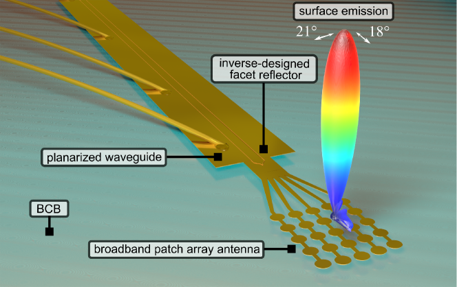
Here, we use inverse-designed end facet reflectors for precise control of the mirror losses and output power, and couple the optical mode to a surface-emitting patch array antenna, all monolithically integrated on the same photonic chip, as illustrated in Fig. 1. All the designed components have been optimized for an octave-spanning emission spectrum between 2-4 THz and improve the output power and far-field pattern while featuring broadband comb states simultaneously.
Results
Inverse-designed end facet reflectors
We first address the limited output powers due to the high reflectivity of cleaved end facets of double metal waveguidesS. Kohen and Hu (2005). In our recent work, we have shown that the planarized waveguide platform enables the reduction of end facet reflectivities by coupling the active waveguide into a passive waveguide, defined with a metallic stripe on top of the surrounding low-loss polymer material with a lower refractive index (BCB, n = 1.57) Senica et al. (2022). In the simplest configuration, a flat dry-etched planarized facet results in a reduced reflectivity of around R = 23% at a frequency of 3 THz into the passive waveguide. This is already a remarkable reduction with respect to the cleaved facet value of .
In order to have precise control of the facet reflectivity over a broad bandwidth, we implemented an inverse design approach based on adjoint optimization Lalau-Keraly et al. (2013). In recent years, inverse design has emerged as a powerful design and optimization tool in various areas and applications in photonics Molesky et al. (2018). The main advantage of such an approach is that instead of manual parameter sweeps and fine-tuning to achieve a high-performance device design, an optimization algorithm is used to automatically adapt the structure in an iterative loop to maximize the desired figure of merit without any user input.
In our specific geometry, we implemented an inverse-design shape optimization simulation loop, where the outline shape of the end facet is modified to match the desired reflectivity value. The details of the parametrization and implementation can be found in the Supplemental Material. Due to the symmetric planarized waveguide structure, only a 2D slice of the structure and an in-plane (x-y, perpendicular to the growth direction z of the heterostructure) propagation simulation are required. Additionally, the adjoint optimization approach features very fast convergence, as it only requires two simulations of the current structure geometry (a forward and a backward propagation simulation) to compute the gradients and update all the geometrical parameters in a single step. These favourable aspects result in a very efficient optimization routine which produces optimized designs after only around 25 iterations, taking less than an hour on a normal desktop computer.
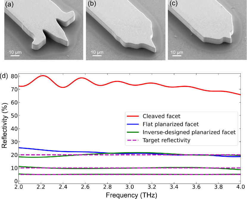
In Fig. 2(a-c), we show SEM images of fabricated dry-etched inverse-designed end facets, designed to have a 5%, 10% and 20% reflectivity over octave-spanning spectra between 2-4 THz. Subsequently, the active waveguides are planarized with a low-loss polymer BCB and the top metallization is defined (see Ref. Senica et al. (2022) for details). A comparison between simulated reflectivities of cleaved, flat planarized, and inverse-designed planarized facets is shown in Fig. 2(d). The facets do not induce any considerable group delay dispersion after reflection, which could otherwise be detrimental to comb formation.
Surface-emitting patch array antenna
After a partial reflection at the planarized end facet, the optical mode is guided within a passive waveguide and coupled into a surface-emitting patch array antenna. As the propagating light wave spreads out into the antenna branches, the individual patches are oscillating in phase and combine into a narrow vertical beam. The basic design intended for single-mode operation was presented in Ref. Bosco et al. (2016).
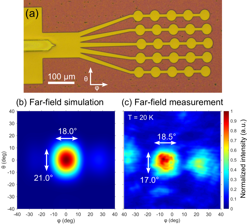
Here, we developed a broadband patch array antenna, shown in the optical microscope image in Fig. 3(a). This design has also been optimized for octave-spanning emission spectra, matching the same broad frequency range as the reflector structures. First, to reduce the beam divergence, the antenna emission area was enlarged by increasing the number of patch elements to (5x5). For broadband emission, the optimal shape, size and positioning of the individual antenna elements were found with full-wave numerical simulations of the surface emission, where a minimal beam divergence and beam steering with frequency were obtained.
In Fig. 3(b) we show the simulated broadband far-field pattern which features a single narrow lobe in the vertical emission direction. The result was obtained by including the emission spectrum of the measured device with frequency-dependent far-field simulation results. Specifically, this was done with a spectrally-weighted linear sum of simulated far-field patterns, as described in more detail in Ref.Senica et al. (2020).
The antenna far-field measurement in Fig. 3(c) agrees well with the simulations with a full-width half-maximum (FWHM) beam divergence of (17.0°x 18.5°). The measurement was performed on a broadband emission sample using a pyroelectric detector (Gentec-EO: THZ2I-BL-BNC) mounted on a motorized angular scanning stage. The laser was driven in micro-pulse (500-ns-long pulses, 20% duty cycle), macro-pulse mode (30 Hz, 50% duty cycle), where the emission spectrum was spanning between around 2.3-3.3 THz.
High-power surface emission
With a reduction of the front end facet reflectivity , the mirror losses are increased through the relation:
| (1) |
where is the waveguide length and the back mirror reflectivity. On the one hand, together with waveguide losses , this increases the total losses with an expected increase of the lasing threshold. On the other hand, the slope efficiencyFaist (2013) should be increased:
| (2) |
When comparing different devices fabricated using the same active region, only the ratio is changing.
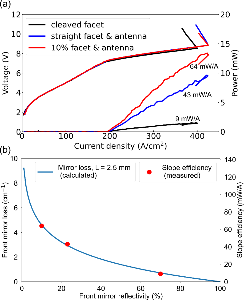
To evaluate the performance of the inverse-designed end facet reflectors, we experimentally compare three different front (extracting) facets of devices processed on the same chip. These are a cleaved facet, a flat planarized facet with the antenna, and a 10% reflectivity inverse-designed planarized facet with the antenna. The first one has a high-reflectivity back facet and a total length of 2.8 mm, while both antenna samples have a cleaved back facet and a length of 2.5 mm. All the samples have the same active waveguide width of to ensure the same waveguide loss and nearly the same total active device area (difference of <5%).
In Fig. 4(a), we plot the measured LJV curves of the three devices, all characterized under the same operating conditions (heat sink temperature of 20 K, 500 ns pulses and a duty cycle of 20%). The output power was measured by a large area calibrated absolute power meter (Thomas Keating Ltd.), which ensures the whole THz emission is collected (even in the case of poor far-field patterns of cleaved facets). When measuring the THz emission within a narrower range of spatial angles (typical for spectroscopy experiments), the improved collection efficiency due to the antenna would result in an even more favourable ratio of slope efficiencies. The comparison of calculated and experimental results for the three devices is summarized in Table 1.
| Parameter | Cleaved facet | Flat facet | 10% facet |
|---|---|---|---|
| (%) | 70 | 23 | 10 |
| Length (mm) | 2.8 | 2.5 | 2.5 |
| (mA) | 178 | 195 | 195 |
| (A/cm2) | 185 | 195 | 195 |
| (cm-1) | 0.64 | 2.94 | 4.61 |
| (cm-1) | 20.6 | 23.7 | 25.3 |
| (mW/A) | 9 | 43 | 64 |
| (mW) | 1.5 | 9.5 | 13.5 |
| ratio | 1 | 4.6 | 7.2 |
| ratio | 1 | 4.8 | 7.1 |
When replacing the front cleaved facet with a planarized antenna-coupled facet, the threshold current density only increases slightly (from 185 A/cm2 to 195 A/cm2). This suggests that for such waveguide lengths ( = 2.5 mm and longer), the total losses are dominated by waveguide losses. Indeed, the waveguide losses of double metal waveguides are estimated to be in the order of 20 cm-1(due to the overlap with lossy metals, intersubband absorption and scattering losses from sidewall roughness), while the computed front mirror losses are below 5 cm-1 for all the considered types of facets. In such a case, the comparison of slope efficiencies can be simplified from to . In Fig. 4(b), we plot the calculated front mirror loss (blue line) and the measured slope efficiencies (red dots). As these follow the same dependence versus the front mirror reflectivity, we are indeed in a regime where waveguide losses dominate over mirror losses. The measured slope efficiency of 64 mW/A of the sample with the 10% inverse-designed facet and the antenna is a factor of 7.1 higher than for the cleaved facet reference sample, with a measured peak power of 13.5 mW. We should also note here that while reducing the reflectivity to even lower values (close to ) is tempting in terms of predicted slope efficiencies, the quickly increasing mirror losses would start to increase the laser threshold significantly, eventually preventing lasing.
Broadband frequency combs
After demonstrating the improved far-field and outcoupling efficiency properties, we now highlight the broadband frequency comb performance. It is worth noting that a reduced cavity feedback has been predicted to be beneficial also for the comb operation itselfHumbard and Burghoff (2022); Beiser et al. (2021); Senica et al. (2022).
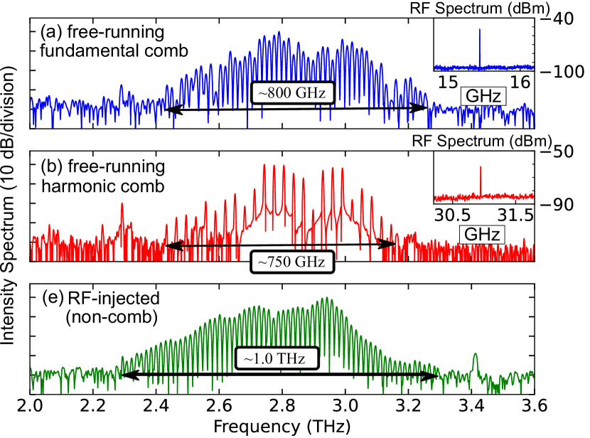
In Fig. 5, we show the measured THz and RF spectra of the 10% reflectivity inverse-designed facet device from the previous section (length = 2.5 mm, width = ). The device was operated in continuous wave (CW) at a heat sink temperature of 30 K. In panel (a), we show a free-running fundamental comb spanning around 800 GHz with a single strong RF beatnote at the roundtrip frequency of = 15.4 GHz. Free-running harmonic comb statesKazakov et al. (2017); Forrer et al. (2021); Senica et al. (2023) are observed as well, where the mode spacing is an integer multiple of . A free-running second harmonic comb spanning around 750 GHz is shown in panel (b), with a single RF beatnote at .
By injecting a strong RF signal into the laser cavity, the emission can be further broadenedSenica et al. (2022); Schneider et al. (2021), as shown in panel (c). However, when the injected RF signal power is too high (typically above 20-30 dBm power at the source, depending on the injection frequency and sample dimensions), this can also produce incoherent (non-comb) states. These can occur due to the limiting chromatic dispersion or due to a voltage swing beyond the threshold/rollover bias point.
Conclusion
In conclusion, we have presented a new, high-performance planarized THz quantum cascade laser geometry, where inverse-designed end facet reflectors coupled to surface-emitting antennas result in a seven-fold improvement of the slope efficiency. All the components are optimized for octave-spanning emission spectra, and the measured far-field patterns of broadband devices feature FWHM beam divergences of (17.0°x 18.5°). The devices operate as broadband frequency combs spanning 800 GHz, with a peak power as high as 13.5 mW. Since the end facet reflectors and antenna are separated by a passive waveguide, we have decoupled the laser mirror reflectivities and the outcoupling structure, allowing for independent control of both aspects.
Moreover, by further reducing the mirror reflectivities and improving the output beam quality, external cavityHugi, Maulini, and Faist (2010); Wysocki et al. (2005) broadband THz QCLs could be fabricated, where the comb repetition rate is continuously tunable by an external mirror/grating. In principle, a near-zero reflectivity end facet can be fabricated by an adiabatic tapered transition between the active and the passive waveguide, facilitating the lasing operation on external cavity modes. In contrast to THz QC-VECSELs Curwen, Reno, and Williams (2018); Wu et al. (2023), comb operation should be more easily obtained as the planarized ridge waveguide can naturally provide both a broad gain and many longitudinal lasing modes.
Finally, it is important to emphasize that the presented device is a general layout that can be used with any type of THz QCL active material to engineer the far-field properties and enhance the outcoupling efficiency with a planar and monolithic fabrication technology. In combination with high-power, high-temperature epilayers such as the ones presented in Refs. Bosco et al. (2019); Khalatpour et al. (2020), the peak powers of simple ridge devices could easily go into the Watt-level range while simultaneously being directed into a narrow beam due to the antenna.
Acknowledgements
The authors gratefully acknowledge funding from the ERC Grant CHIC (grant n. 724344) and in part from the SNF MINT project n. and EU project iFLOWS (grant n. 101057844).
Competing Interests
The authors declare that they have no competing financial interests.
Correspondence
*Correspondence should be addressed to U. Senica (email: usenica@phys.ethz.ch) and G. Scalari (email: scalari@phys.ethz.ch).
Data availability
All the simulation and experimental data supporting this study are available from the corresponding author upon reasonable request.
References
References
- Köhler et al. (2002) R. Köhler, A. Tredicucci, F. Beltram, H. E. Beere, E. H. Linfield, A. G. Davies, D. A. Ritchie, R. C. Iotti, and F. Rossi, “Terahertz semiconductor-heterostructure laser,” Nature 417, 156–159 (2002).
- Burghoff et al. (2014) D. Burghoff, T.-Y. Kao, N. Han, C. W. I. Chan, X. Cai, Y. Yang, D. J. Hayton, J.-R. Gao, J. L. Reno, and Q. Hu, “Terahertz laser frequency combs,” Nature Photonics 8, 462–467 (2014).
- Rösch et al. (2016) M. Rösch, G. Scalari, G. Villares, L. Bosco, M. Beck, and J. Faist, “On-chip, self-detected terahertz dual-comb source,” Applied Physics Letters 108, 171104 (2016).
- Amanti et al. (2009) M. I. Amanti, M. Fischer, G. Scalari, M. Beck, and J. Faist, “Low-divergence single-mode terahertz quantum cascade laser,” Nature Photonics 3, 586–590 (2009).
- Bosco et al. (2016) L. Bosco, C. Bonzon, K. Ohtani, M. Justen, M. Beck, and J. Faist, “A patch-array antenna single-mode low electrical dissipation continuous wave terahertz quantum cascade laser,” Appl. Phys. Lett 109, 201103 (2016).
- Rösch et al. (2017) M. Rösch, I.-C. Benea-Chelmus, C. Bonzon, M. J. Süess, M. Beck, J. Faist, and G. Scalari, “Broadband monolithic extractor for metal-metal waveguide based terahertz quantum cascade laser frequency combs,” Applied Physics Letters 111, 021106 (2017).
- Xu and Wang (2012) X. Xu and Z. Wang, “Thermal conductivity enhancement of benzocyclobutene with carbon nanotubes for adhesive bonding in 3-d integration,” IEEE Transactions on Components, Packaging and Manufacturing Technology 2, 286–293 (2012).
- Lee et al. (2007) A. W. M. Lee, Q. Qin, S. Kumar, B. S. Williams, Q. Hu, and J. L. Reno, “High-power and high-temperature thz quantum-cascade lasers based on lens-coupled metal-metal waveguides,” Optics letters 32, 2840–2842 (2007).
- Senica et al. (2020) U. Senica, E. Mavrona, T. Olariu, A. Forrer, M. Beck, J. Faist, and G. Scalari, “An antipodal Vivaldi antenna for improved far-field properties and polarization manipulation of broadband terahertz quantum cascade lasers,” Applied Physics Letters 116, 161105 (2020).
- S. Kohen and Hu (2005) B. S. W. S. Kohen and Q. Hu, “Electromagnetic modeling of terahertz quantum cascade laser waveguides and resonators,” Journal of Applied Physics 97, 053106 (2005), publisher: American Institute of Physics.
- Senica et al. (2022) U. Senica, A. Forrer, T. Olariu, P. Micheletti, S. Cibella, G. Torrioli, M. Beck, J. Faist, and G. Scalari, “Planarized THz quantum cascade lasers for broadband coherent photonics,” Light: Science & Applications 11, 347 (2022).
- Lalau-Keraly et al. (2013) C. M. Lalau-Keraly, S. Bhargava, O. D. Miller, and E. Yablonovitch, “Adjoint shape optimization applied to electromagnetic design,” Optics Express 21, 21693 (2013).
- Molesky et al. (2018) S. Molesky, Z. Lin, A. Y. Piggott, W. Jin, J. Vucković, and A. W. Rodriguez, “Inverse design in nanophotonics,” Nature Photonics 12, 659–670 (2018).
- Faist (2013) J. Faist, Quantum cascade lasers, first edition ed. (Oxford University Press, Oxford, United Kingdom, 2013).
- Humbard and Burghoff (2022) L. Humbard and D. Burghoff, “Analytical theory of frequency-modulated combs: generalized mean-field theory, complex cavities, and harmonic states,” Optics Express 30, 5376–5401 (2022).
- Beiser et al. (2021) M. Beiser, N. Opačak, J. Hillbrand, G. Strasser, and B. Schwarz, “Engineering the spectral bandwidth of quantum cascade laser frequency combs,” Optics Letters 46, 3416–3419 (2021).
- Kazakov et al. (2017) D. Kazakov, M. Piccardo, Y. Wang, P. Chevalier, T. S. Mansuripur, F. Xie, C.-e. Zah, K. Lascola, A. Belyanin, and F. Capasso, “Self-starting harmonic frequency comb generation in a quantum cascade laser,” Nature Photonics 11, 789 (2017).
- Forrer et al. (2021) A. Forrer, Y. Wang, M. Beck, A. Belyanin, J. Faist, and G. Scalari, “Self-starting harmonic comb emission in thz quantum cascade lasers,” Applied Physics Letters 118, 131112 (2021).
- Senica et al. (2023) U. Senica, A. Dikopoltsev, A. Forrer, S. Cibella, G. Torrioli, M. Beck, J. Faist, and G. Scalari, “Frequency-modulated combs via on-chip field enhancement,” (2023), arXiv:2305.01483 [physics.optics] .
- Schneider et al. (2021) B. Schneider, F. Kapsalidis, M. Bertrand, M. Singleton, J. Hillbrand, M. Beck, and J. Faist, “Controlling quantum cascade laser optical frequency combs through microwave injection,” Laser & Photonics Reviews 15, 2100242 (2021).
- Hugi, Maulini, and Faist (2010) A. Hugi, R. Maulini, and J. Faist, “External cavity quantum cascade laser,” Semiconductor Science and Technology 25, 083001 (2010).
- Wysocki et al. (2005) G. Wysocki, R. F. Curl, F. K. Tittel, R. Maulini, J.-M. Bulliard, and J. Faist, “Widely tunable mode-hop free external cavity quantum cascade laser for high resolution spectroscopic applications,” Applied Physics B 81, 769–777 (2005).
- Curwen, Reno, and Williams (2018) C. A. Curwen, J. L. Reno, and B. S. Williams, “Terahertz quantum cascade vecsel with watt-level output power,” Applied Physics Letters 113, 011104 (2018).
- Wu et al. (2023) Y. Wu, C. A. Curwen, M. Shahili, J. L. Reno, and B. S. Williams, “RF Injection Locking of THz Metasurface Quantum-Cascade VECSEL,” Laser & Photonics Reviews 2023, 2300007 (2023), https://onlinelibrary.wiley.com/doi/pdf/10.1002/lpor.202300007 .
- Bosco et al. (2019) L. Bosco, M. Franckié, G. Scalari, M. Beck, A. Wacker, and J. Faist, “Thermoelectrically cooled THz quantum cascade laser operating up to 210 K,” Applied Physics Letters 115, 010601 (2019).
- Khalatpour et al. (2020) A. Khalatpour, A. K. Paulsen, C. Deimert, Z. R. Wasilewski, and Q. Hu, “High-power portable terahertz laser systems,” Nature Photonics (2020), 10.1038/s41566-020-00707-5.