Design and Characterization of a Novel Motion Conversion Element: Curved Groove Ball Bearing without Retainer
Abstract
An unconventional and innovative mechanical transmission component, the Curved Groove Ball Bearing without Retainer (CGBBR), is introduced in this paper to facilitate the conversion between rotary and reciprocating motion. The CGBBR boasts several advantages over conventional motion conversion mechanisms, including a streamlined and compact structure, as well as the mitigation of high-order vibrations. This paper delves into the design methodology, structural attributes, kinematic principles, and dynamic response properties of the CGBBR. A novel design method named closed curve envelopment theory is proposed to generate the distinctive spatial surface structure of the CGBBR. Moreover, a design scheme is presented that employs the concept of diameter-stroke ratio for CGBBR implementation. A calculation methodology is also introduced for determining the number of rolling elements within the CGBBR, which serves as the foundation for subsequent optimization design. This paper deeply analyzes the kinematics principle of CGBBR and provides a new insight of motion conversion in mechanism.
keywords:
Ball bearing , Motion conversion , Amplitude , Motion cycle , Curved groove[nwafu]organization=College of Mechanical and Electronic Engineering, addressline=Northwest A&F University, city=Yangling, postcode=712100, state=Shaanxi, country=China
[ZN]organization=College of Optical, Mechanical and Electrical Engineering, addressline=Zhejiang A&F University, city=Hangzhou, postcode=311300, state=Zhejiang, country=China
1 Introduction
Rotational motion and reciprocating motion are prevalent types of motion in engineering. They are commonly observed in the motions of the crankshaft and piston of engines and compressors, among others[1]. In the field of mechanical design, there is a constant requirement for transformation between rotational motion and reciprocating motion. However, motion conversion mechanisms are restricted to a few select structures, such as the crankshaft, cam and toggle mechanisms[2]. These motion conversion mechanisms possess distinct advantages and drawbacks. Therefore, it is crucial to develop innovative motion conversion mechanisms in order to optimize the structural design of various mechanical devices, including engines, from both a theoretical and practical perspective.
The transformations between rotary and reciprocating motion are frequently achieved through the use of crank-slider and ball screw. The study of crank-slider and ball screw is well-established in the field of engineering. The available literature focuses on the structural design [3, 4, 5, 6], vibration characteristics[7, 8, 9, 10, 11], wear[12] and failure causes [13, 14, 15] of the crank-slider, as well as the transmission accuracy[16, 17, 18], forward and reverse transmission stability[19, 20] of the ball screw. Crank-slider inherently possess high-order inertial forces as a result of their asymmetrical structure, which causes vibration and noise in operation. Ball screw has a complex structure[21], resulting in difficulty in installation and maintenance[22]. In contrast, curved groove ball bearing without retainer (CGBBR) is composed entirely of axisymmetric rotatable structures. Components of CGBBR exhibit either rotational or reciprocating linear motion, without space translation or any other complex forms of motion, which are difficult to balance[23, 24]. Therefore, CGBBR can eliminate typical issues of vibration and noise in traditional mechanical structures effectively, providing a new solution to the design and optimization of mechanical structures[25, 26].
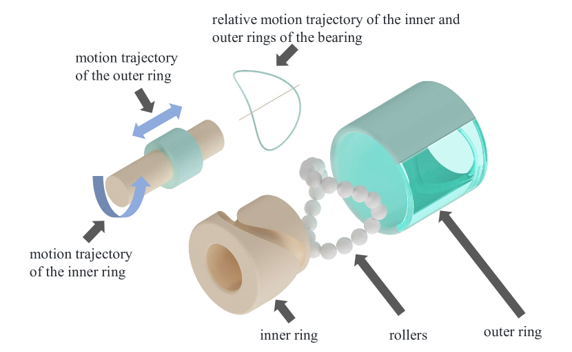
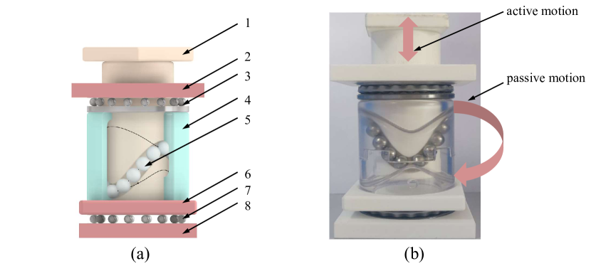
The structure of CGBBR is shown in Fig. 1, consisting of one outer ring, one inner ring, and one set of rolling elements. Unlike conventional ball bearings, the curved groove of this bearing’s outer ring constitutes a spatial surface, generated by traversing a quarter-circle arc along a closed, smooth curve with a specified amplitude and period[23]. Likewise, the inner ring’s curved groove represents a spatial surface created by progressing a three-quarter-circle arc in accordance with a closed, smooth curve, also exhibiting a defined amplitude and period. Rolling elements are distributed in the curved groove of the inner ring. When the inner ring remains stationary and the curved groove on the outer ring interacts with the rolling elements at various positions, the outer ring must execute a reciprocating motion while rotating. When the outer ring does not rotate and the inner ring does not move axially, the outer ring will reciprocate upon the rotation of the inner ring. Similarly, the active and passive sequence of the inner and outer ring can be interchanged. This interchangeability provides more flexibility and opportunities for experimentation and innovation.
CGBBR exhibits substantial differences from conventional bearings. In ordinary bearings, the raceway centerline projection onto the radial plane assumes a circular shape, whereas the raceway center curves for both inner ring and outer ring of CGBBR form closed, smooth three-dimensional curves, also projecting circularly onto the radial plane. Furthermore, the cage in CGBBR has been eliminated, and the rolling elements are completely mounted in the inner ring raceway. Consequently, traditional bearings’ design methods, kinematic properties, and vibration characteristics become unsuitable for CGBBR. Therefore, it is imperative to analyze the structure, design principles, kinematic laws, and dynamic response characteristics of CGBBR. This comprehensive analysis will provide a theoretical basis for the optimization of the structure, standardization of production, and future widespread implementation of CGBBR.
There are three main contributions in this paper. Firstly, this paper proposes a novel type of bearing called CGBBR and the design method of it, which is named closed curve envelopment theory. The feasibility of the method is verified by manufacturing a real CGBBR, demonstrating that CGBBR can completely realize motion conversion. Secondly, the diameter-to-stroke ratio is proposed as the key parameter for optimal design of CGBBR. Finally, vibration signal of CGBBR is analyzed using time-frequency analysis to identify the presence of periodic pulse clusters resulting from rolling element collisions. The analysis reveals that the collisions occur when the inner ring and outer ring raceway center curves align in the same direction.
The remainder of this paper is organized as follows: Section 2 presents the design principles and structural features of CGBBR, along with a proposed design scheme; Section 3 examines the design parameters, the motion equations for any point on the bearing, and the rolling element’s motion equation; Section 4 constructs a physical prototype of CGBBR, validating the design method’s feasibility and the bearing function’s comprehensiveness; Section 5 investigates the actual vibration signals of CGBBR, analyzing its characteristics and underlying causes; Finally, conclusions are provided in Section 6.
2 Structural design of CGBBR
2.1 Design background
In transmission mechanisms, spatial curves are essential for converting rotary motion into reciprocating motion, as they constrain the trajectory of driven components, allowing for control and adjustment of their motion via the curve’s geometry[2]. For example, spatial cam employs spatial curve to regulate the motion of driven components. While the cam acts as a driving component, it rotates to lead the driven component along the curved path, facilitating reciprocating motion[27, 28]. Similarly, in ball screw mechanisms, balls roll along a spatial helical curve in the raceway[21], propelling the nut into linear reciprocating motion. The mentioned mechanisms share a common feature: the axial projection of the driven component’s motion along the spatial curve forms a reciprocating straight line. Simultaneously, mechanisms employed must control and stabilize the motion of the follower along the curved trajectory. CGBBR features inner and outer races with curved raceways based on spatial curves, with rolling elements fully installed in the inner raceway, enabling the interchange between rotary and reciprocating motions. The aforementioned features of the motion conversion mechanisms are applied to the design of CGBBR. We optimized the structure by guiding the follower’s movement along a sinusoidal curve.
2.2 Design theory
CGBBR combines the structural features of space cam, ball screw and conventional bearings, making the traditional design method insufficient for meeting its structural requirements. Design of CGBBR is developed utilizing closed curve envelopment theory, which combines the envelope theory [29, 30, 31, 32] with swept surface theory[33, 34]. This approach calculates the space envelope of a 3D curve trajectory. The surfaces of inner ring and outer ring of CGBBR are formed by sweeping a spherical surface based on both the 3D curve and its envelope.
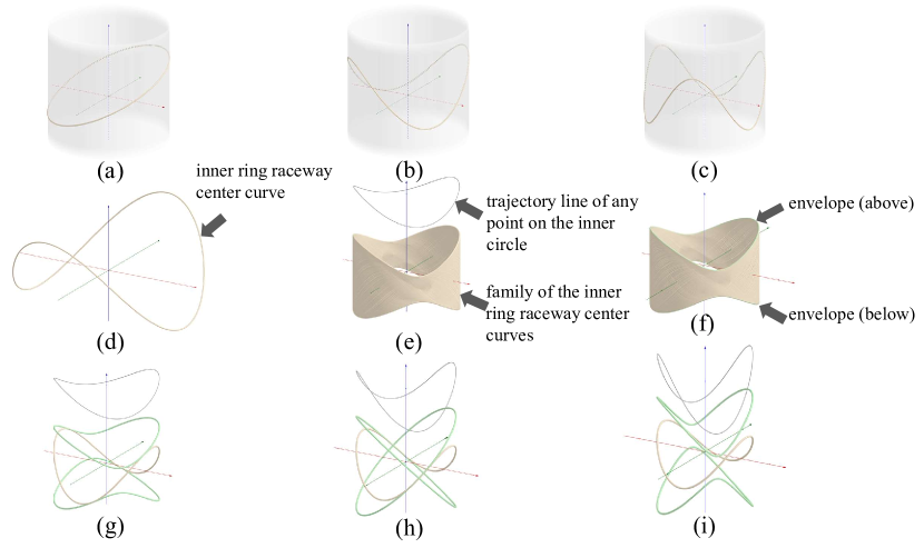
Firstly, the function of envelope theory in CGBBR design is expounded. The inner ring raceway center curve (IRRCC) of the CGBBR is shifted one circle along the aforementioned sinusoidal displacement curve to produce a family of spatial curves. The envelope of this spatial curve family is the outer ring raceway center curve (ORRCC). IRRCC is a closed, smooth, and non-self-intersecting 3D curve that surrounds the bearing’s rotation axis[28], which is defined by the Equation (1):
| (1) |
IRRCC is a wavy line on a cylindrical surface, which, when divided along its “peaks” or “valleys”, can be unfolded into a cosine curve on a plane[23]. In Equation (1), represents the amplitude of the cosine curve. represents the radius of the cylindrical surface enclosed by IRRCC. is the number of “peaks” or “valleys” of IRRCC. Subfigures (a)-(c)of Fig. 2 indicate the above relationships.
As the displacement curve of the follower is sinusoidal, the trajectory of any point on the inner ring with respect to the outer ring can be expressed as Equation (2):
| (2) |
where is the motion amplitude of IRRCC, is the number of IRRCC reciprocal movements in one rotation time. Since the number of “peaks” and “valleys” of the inner ring and the outer ring of CGBBR is equal, .
The space curve family formed by the IRRCC, rotating along its trajectory, can be represented as a single-parameter space curve family denoted by the equation , which can be specifically written as:
| (3) |
where , is a parameter. The family of spatial curves is shown in subfigure (e) of Fig. 2.
Envelopes of the family of the spatial curves are ORRCC, which can be expressed as:
| (4) |
Due to the presence of “peaks” and “valleys” in IRRCC, distinct envelope lines are generated when moving along a sine trajectory. The “peaks” and “valleys” each produce their own envelope lines, which can be expressed in Equation (5) and Equation (6) respectively.
| (5) |
| (6) |
Subfigures (d)-(f) in Fig. 2 demonstrate the application of envelope theory in the design of CGBBR.
As shown in subfigures (g)-(i) of Fig. 2: When , IRRCC is tangent to upper ORRCC and lower ORRCC. When , IRRCC is tangent to upper ORRCC and lower ORRCC. Upper ORRCC intersects with lower ORRCC. When , IRRCC can be tangent to either the upper or lower ORRCC, but not both simultaneously.
Based on Equations (1)-(6) and Fig. 2, we define “single reciprocating movement” as the motion in which the inner ring moves away from the initial position, and then returns to the initial position. The following relationship can be obtained:
-
1.
A single rotation of CGBBR corresponds to reciprocating motions.
-
2.
A reciprocating motion corresponds to an angle change of
-
3.
The maximum displacement of a single reciprocating motion is
The curved surface raceways, accomplished through the intricate swept surface theory, constitute the fundamental architecture of both the inner ring and outer ring of CGBBR. For instance, as illustrated in Fig. 3 (a), during the design process of the inner race groove surface, the rolling element moves along the IRRCC for one revolution, resulting in the development of the curved surface of the inner race groove which is called the swept surface. The swept surface is depicted in subfigure (b) of Fig. 3. Equation (7) can be used to represent the swept surface.
| (7) |
where is the radius of rolling element. and are the polar angle and azimuth angle in the spherical coordinate system, which can be calculated using the following formulas.
| (8) |
where , , and respectively represent the derivatives in the three directions at time .
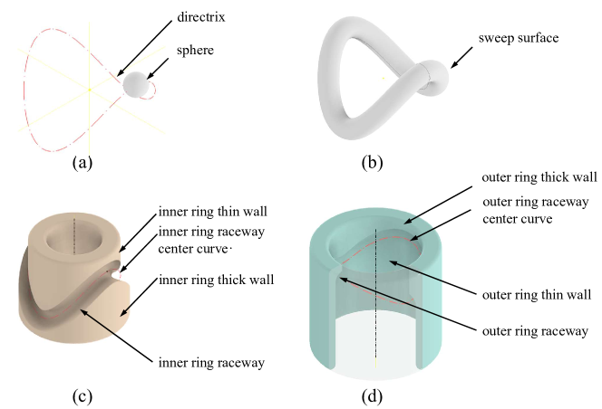
Subfigures (c) and (d) in Fig. 3 depict the CGBBR structure designed using the envelope theory and swept surface theory. Primary components of the inner ring consist of the inner ring’s thin wall, thick wall, raceway, and the centerline of raceway. Radius of inner ring thin wall is equal to the radius of IRRCC. Inner ring thin wall is separated from inner ring thick wall by inner ring raceway. Inner ring raceway is formed by subtracting the swept surface from inner ring using boolean operations. Similarly, main structures of outer ring include: outer ring thin wall, outer ring thick wall, outer ring raceway, and outer ring raceway centerline. Radius of the outer ring thick wall is equal to the radius of ORRCC. The outer ring raceway separates the outer ring thick wall from the outer ring thin wall. Outer ring raceway is constructed through a boolean subtraction of the swept surface from the outer ring, thus creating a precisely engineered profile. Given that the radius of IRRCC matches that of ORRCC, radius of inner ring thin wall and outer ring thick wall are identical, and so are those of inner ring thick wall and outer ring thin wall.
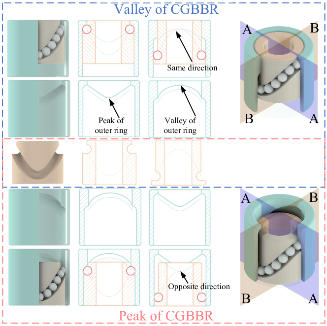
Apart from the distinct component structure, CGBBR also possesses a significantly different assembly structure compared to ordinary bearings, which is mainly due to the structure with curvatures in its inner ring and outer ring. We will demonstrate this using the operational process of a CGBBR that has two “peaks” and two “valleys”. Fig. 4 shows a transparency of the outer ring of CGBBR to enable a clear observation of the contact and positional relationships of each component during its movement. The operation of CGBBR involves constant positional changes of the inner and outer rings. To differentiate between these positions, the following nomenclature will be utilized: the sharp points on the ORRCC correspond to the “peaks” situated on the outer ring, whereas relatively smooth points correspond to the “valleys” located on the outer ring. The “valleys” in CGBBR is formed by the alignment of IRRCC and ORRCC in the same direction, while the “peaks” is formed when they are aligned in opposite directions. The alternation of “peaks” and “valleys” in CGBBR affects the angular and positional relationships between its inner ring and outer ring, which explains its capability to transition between rotary and reciprocating motion.
3 Parameter analysis and kinematic analysis of CGBBR
3.1 Diameter stroke ratio
The motion conversion ability of CGBBR is directly influenced by the relative motion trajectory equation of the bearing’s inner ring and outer ring. As defined in Equation (2), since the curve transforms into a cosine curve after being unfolded, its steepness and smoothness are directly affected by the period and amplitude. Accordingly, it is imperative to make appropriate adjustments to these two variables. Equation (9) displays the displacement curve of the engine’s crank connecting rod mechanism, which can be simplified into a cosine curve, as shown in Equation (10).
| (9) |
| (10) |
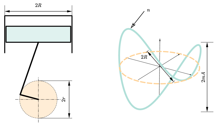
where is the distance of the end of the connecting rod from the crank axle, is the length of the connecting rod, is the length of the crank, and is the angle of the crank measured from top dead center[2]. In balancing the effect of the relationship between period and amplitude in the displacement curve, the crank-connecting rod mechanism employs an appropriate cylinder bore to stroke ratio(). The of engines currently ranges from 0.887 to 1.342[6, 4]. When the crank connecting rod mechanism completes one rotation, the piston reciprocates once. Similarly, as the CGBBR makes one revolution, the inner and outer rings move times relative to each other. With reference to , we proposed the definition of diameter stroke ratio() of CGBBR, which represents the ratio between diameter of the trajectory curve and the stroke. By utilizing the parameters depicted in Fig. 5,
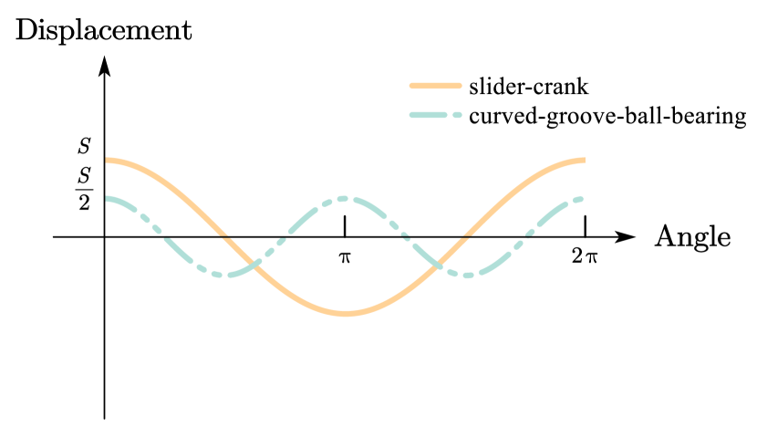
and . Alterations to , the number of reciprocating motions for each revolution of the CGBBR, will have an impact on its stroke. To ensure the stability of , modifications to are required. This entails altering at least one parameter either in or . The stroke of the crank-connecting rod mechanism is times the stroke of CGBBR when and are identical. The displacement of the crank-connecting rod and CGBBR with respect to the rotational angle is compared in Fig. 6, where is equal to and is equal to 2.
3.2 Calculation of the number of rolling elements of CGBBR
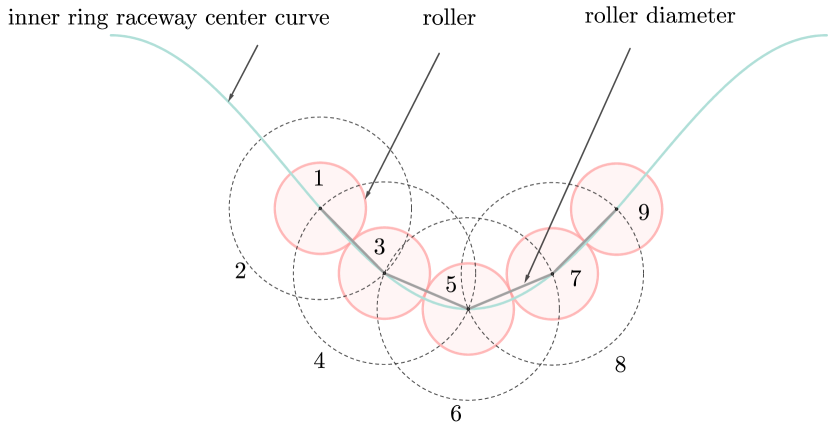
The rolling elements of CGBBR are fully filled in the curved groove raceway of the inner ring, which is different from the structure of ordinary bearings. As such, it is necessary to determine the precise number of rolling elements for the CGBBR. This paper presents a methodology for accomplishing this task. Assuming that the rolling elements are rigid and that adjacent rolling elements are in tangent with each other, the centers of these rolling elements are positioned on IRRCC. Calculating the number of rolling elements involves the following steps:
-
1.
Select a point on IRRCC as the center of the first rolling element and form a spherical surface with the rolling element diameter as the radius. By solving the equations of the spherical surface and the center curve of the raceway, determine two intersection points.
-
2.
Use one of the intersection points as the center of the second rolling element and form another spherical surface with the rolling element diameter as the radius. By solving the equations of the second spherical surface and IRRCC, determine two intersection points. Select the intersection point on the vector connecting the centers of the first and second rolling elements as the position of the center of the next rolling element.
-
3.
Repeat the above steps, using the current center of the rolling element as the starting point, forming a new spherical surface, and solving the equations to determine the intersection point, until the distance between the intersection point and the line connecting the center of the first rolling element is less than the radius of the rolling element.
-
4.
Calculate the total number of rolling elements.
To facilitate understanding, we utilize the form of a schematic diagram to describe the process described above, as shown in Fig. 7.
3.3 Kinematic analysis of CGBBR
CGBBR has the capability to switch between rotational and reciprocating motion. Regardless of whether the inner ring or outer ring acts as the driving component, the fundamental characteristic of its motion is that the cylinder undergoes both rotational and reciprocating motion along its own axis simultaneously. Therefore, the motion model of CGBBR can be conceptualized as the trajectory of any point on a cylinder during its simultaneous rotation and reciprocating motion. The motion can be decomposed into two independent components: rotational and reciprocating. These components can be described using homogeneous transformation matrices[21]. Rotational motion is performed around the axis of the bearing, represented by the rotational matrix assuming an angular velocity of . The equation for periodic motion can be expressed as according to Equation (2). This equation can also be represented by the periodic matrix . Compound motion is the combination of rotational and reciprocating motions, which can be represented as a matrix multiplication of rotation matrix and translation matrix. The matrix representation of reciprocating and rotational motion is:
| (11) |
The motion of any point on the inner ring or outer ring can be represented using the matrix . Assuming that the rolling element can be approximated as a mass point moving on the inner ring raceway, its trajectory can be represented as movement along the IRRCC. Represented by a matrix:
| (12) |
The homogeneous transformation matrix representing the motion of the cylinder can be utilized to calculate the rolling element’s motion equation by multiplying with the mass point coordinates of the local coordinate system. To obtain the displacement equation of the rolling element, the Equation (2) must first be expanded into a homogeneous coordinate form. Then, the resulting equation is multiplied by the homogeneous transformation matrix .
| (13) |
Converting this to Cartesian coordinates is:
| (14) |
4 Kinematic verification of CGBBR
Design method of CGBBR proposed in Section 2 will be experimentally validated in this section, alongside functionalities of CGBBR. Specifically, this section aims to verify the capability of CGBBR to convert rotary motion to reciprocating motion and vice versa, as well as the function of compound motion. The CGBBR parameters used in the experiment are shown in the Table 1:
| Parameter/unit | Value |
|---|---|
| Raceway Center Curve Radius /mm | 25 |
| Raceway Center Curve Amplitude /mm | 25 |
| Reciprocating amplitude /mm | 12.5 |
| Reciprocating times per revolution /times | 2 |
| Roller element diameter/mm | 10 |
| Number of rolling elements/number | 20 |
To assess the capacity of CGBBR in transforming rotary motion to reciprocating motion, we employed an actual object. Specifically, 3D printing technology was utilized to create the inner ring and transparent outer ring using photosensitive resin material[28]. As depicted in Fig. 8.
We evaluated the performance of CGBBR by converting rotary motion of inner ring to reciprocating motion of outer ring. We constrain the degrees of freedom of the inner ring and outer ring, allowing only rotary motion for the inner ring, while the outer ring is restricted to reciprocate. The implementation process entails positioning the initial position at the “valley” of the bearing, driving the inner ring rotation with the stepping motor, and applying pressure on the upper part of the outer ring using the spring. The inner ring rotates as the outer ring moves upwards, continuously approaching bearing’s “peak”. After reaching the “peak”, the inner ring continues to rotate while the spring, raceway, and rolling elements work together to move the outer ring downward until it reaches the “valley” of bearing. The transformation from rotational motion to reciprocating motion can be achieved repeatedly. Please watch the accompanying video for demos.
The performance of CGBBR was assessed by transforming inner ring’s reciprocating motion into outer ring’s gyration[25]. As shown in Fig. 9, outer ring of CGBBR includes thrust ball bearings at its upper and lower ends. Therefore, outer ring is restricted to rotary motion. Applying a reciprocating force on the end face of inner ring will result in reciprocation of it, and subsequently push the outer ring to rotate. Please watch the accompanying video for demos.
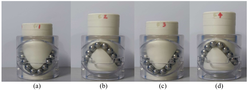
CGBBR’s ability to achieve compound motion is based on the structure described in the literature[25]. The positions that are 90 degrees apart from the outer wall of the inner ring are marked with numbers 1-4, respectively. When a turning moment is applied to the inner ring while outer ring fixed, it will reciprocate along the spatial curve. From a fixed perspective, it will be noticed that the height of the end surface of the inner ring varies in accordance with the alteration of the numbers inscribed on the outer surface of inner ring. please refer to the relevant information in Fig. 10.
The aforementioned three experiments demonstrate the feasible design of CGBBR, which combines the envelope theory and swept surface theory. They also indicate the full range of motion conversion capability of CGBBR.
5 Vibration analysis of CGBBR
5.1 Experiment equipment
Due to an innovative curved raceway that contains rolling elements, CGBBR exhibits distinct vibrational properties compared to conventional bearings[35, 36]. To enhance our understanding and optimize the performance of CGBBR, it is essential to sample and extract vibration signals of this bearing.
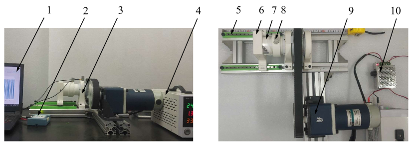
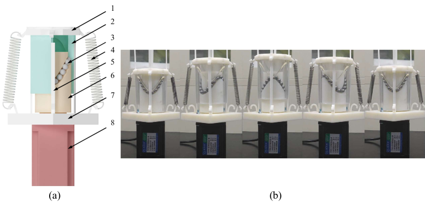
We constructed the acquisition platform for the vibration signals of CGBBR, as illustrated in Fig. 11. The experimental platform functions based on the following working principle: the motor drives the driven shaft, which is rigidly coupled to inner ring. A sliding support mechanism is utilized to establish a connection between outer ring and the slide block of the guide rail. During the rotation of inner ring, outer ring undergoes a lateral displacement along the guide rail, while a vibration sensor affixed to the outer wall of outer ring concurrently captures vertical vibration signals emanating from the bearing. A signal acquisition system consisting of an MCC signal acquisition card and a computer is employed to capture and display the vibration signal emanating from CGBBR in real time.
The parameters of the CGBBR are listed in Table 1. The IEPE piezoelectric accelerometer, CT1010LC, is utilized for measuring the vibration signal. The data acquisition system of MCC is used to collect the vibration acceleration signal of CGBBR. To guarantee sampling accuracy, a sampling frequency of 25000 Hz and a sampling time of 20 seconds were selected.
5.2 Vibration signal characteristics of CGBBR
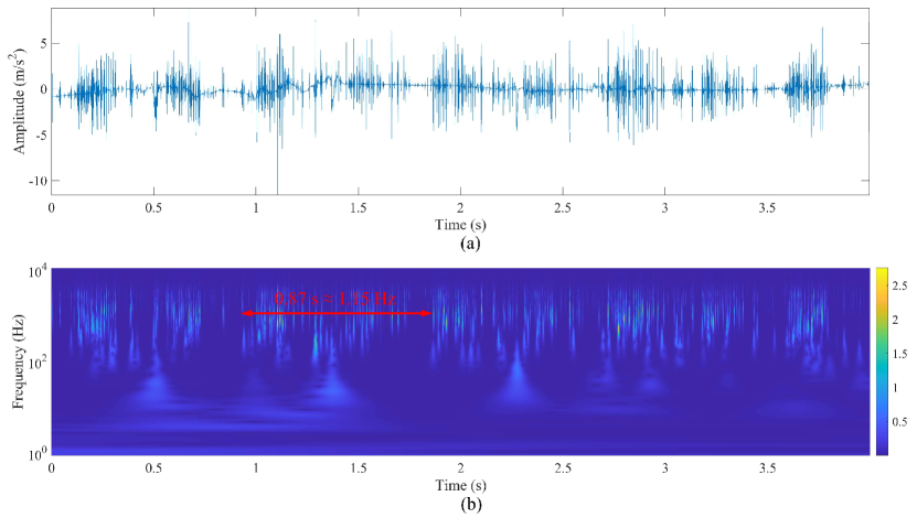
The vibration signal of CGBBR was detected, and its vibration acceleration data was successfully obtained. Fig. 12 presents the time domain and time-frequency domain characteristics of the signal. The signal has a duration of 4 seconds and its shaft rotates at 1.15 Hz[19]. The analysis of both time-domain and time-frequency diagrams revealed periodic pulse clusters in the vibration signal of CGBBR. The time-domain and time-frequency diagrams exhibit that the vibration signal of CGBBR manifests periodic pulse clusters[37, 38, 39]. This distinctive characteristic contrasts with ordinary bearings, which produce periodic pulses only when their raceways sustain damage. Therefore, the vibration characteristics of CGBBR differ significantly from those of conventional bearings. The time-frequency diagram reveals that the periodic pulse clusters occur at the same frequency as the reciprocating motions within one revolution of the CGBBR. Moreover, it is worth noting that the duration of the periodic pulse clusters’ appearance is considerably longer than that of their disappearance.
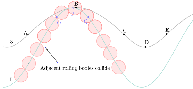
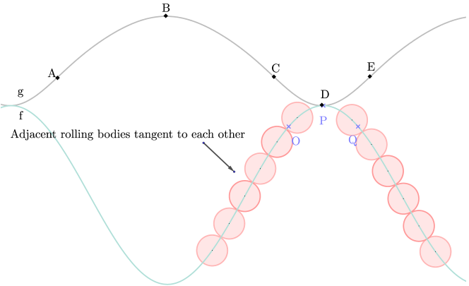
Based on the distinct attributes of CGBBR as a full complement roller bearing, it can be deduced that these pulse clusters originate from the stochastic interactions of rolling elements within the inner ring during the transition from “valleys” to “peaks”. To gain a clearer understanding of the mechanism behind the periodic pulse cluster, a schematic diagram is drawn to depict the contact state between rolling elements at both the “valley” and “peak” of CGBBR. As illustrated in Fig. 13, ORRCC functions as an envelope and remains tangent to the OPQ segment of the IRRCC. When the OPQ segment of IRRCC contacts the ABC segment of ORRCC, both curves share the same direction. This causes the rolling elements to shift towards the center of the OPQ segment, subsequently leading to a looser spacing between the rolling elements on either side of the OPQ segment. This results in collisions, which appear as pulse clusters in the time-frequency diagram. When the OPQ segment of the IRRCC approaches and contacts the CDE segment of the ORRCC, the opposite direction causes the rolling elements of the OPQ segment to be divided at the P point of the IRRCC. Consequently, rolling elements are pushed to both sides, and the adjacent rolling bodies become tangent without causing collisions. As a result, pulse clusters are not generated. The duration of the pulse clusters is longer when they appear compared to when they disappear, which can be attributed to the ABC segment being longer than the CDE segment.
6 Conclusion
CGBBR is a novel type of bearing with a unique structure, kinematics characteristics, and vibration response that distinguishes it from conventional bearings. This paper focused on the composition and design of CGBBR, as well as the motion laws and vibration responses of its components, which led to the following findings:
-
1.
By utilizing the closed curve envelopment theory, a curved groove ball bearing without retainer (CGBBR) was successfully designed, capable of converting rotary and reciprocating motions, as well as facilitating compound motion combining both. The effectiveness of this motion conversion mechanism was experimentally validated, demonstrating its potential for various applications.
-
2.
The diameter-stroke ratio was proposed as a critical parameter for the subsequent optimization design of CGBBR. Additionally, a method for calculating the number of rolling elements was introduced, providing an essential theoretical foundation for further investigation of this bearing.
-
3.
It was discovered that the vibration signals in CGBBR exhibit periodic pulse clusters. The cause of this phenomenon was investigated, and it was determined that it arises when the central curves of the inner and outer raceways align, leading to collisions among the rolling elements. This pulse cluster phenomenon is exclusive to CGBBR and absent in traditional circular bearings. The findings were obtained through experimentation.
Owing to the compact structure and sophisticated motion control capabilities of CGBBR, it holds extensive application prospects in various fields. For instance, it can substitute the crank-slider mechanism in engines for motion conversion, acting as the driving mechanism in compressors, or operating as a control component managing reciprocating and rotary motions in industrial robot joints. This paper lays the groundwork for design optimization, standardized production, and future broad implementation of curved groove ball bearing without retainer.
Declaration of interest
The authors declare that they have no known competing financial interests or personal relationships that could have appeared to influence the work reported in this paper.
Data availability
Data will be made available on request.
Acknowledgement
This research was supported by the Talent start-up Project of Zhejiang A&F University Scientific Research Development Foundation (2021LFR066).
References
- Sclater [2011] N. Sclater, Mechanisms and Mechanical Devices Sourcebook, 5th ed ed., McGraw-Hill, New York, NY, 2011.
- Uicker et al. [2017] J. J. Uicker, G. R. Pennock, J. E. Shigley, Theory of Machines and Mechanisms, fifth edition ed., Oxford University Press, New York, 2017.
- Zhou and Ting [2002] H. Zhou, K. L. Ting, Adjustable slider-crank linkages for multiple path generation, Mechanism and Machine Theory 37 (2002) 499–509. doi:10.1016/S0094-114X(02)00008-3.
- Yamin and Dado [2004] J. A. Yamin, M. H. Dado, Performance simulation of a four-stroke engine with variable stroke-length and compression ratio, Applied Energy 77 (2004) 447–463. doi:10.1016/S0306-2619(03)00004-7.
- Söylemez [2002] E. Söylemez, Classical transmission-angle problem for slider–crank mechanisms, Mechanism and Machine Theory 37 (2002) 419–425. doi:10.1016/S0094-114X(01)00083-0.
- Ozcan and Yamin [2008] H. Ozcan, J. A. Yamin, Performance and emission characteristics of LPG powered four stroke SI engine under variable stroke length and compression ratio, Energy Conversion and Management 49 (2008) 1193–1201. doi:10.1016/j.enconman.2007.09.004.
- Boysal and Rahnejat [1997] A. Boysal, H. Rahnejat, Torsional vibration analysis of a multi-body single cylinder internal combustion engine model, Applied Mathematical Modelling 21 (1997) 481–493. doi:10.1016/S0307-904X(97)00032-2.
- Geveci et al. [2005] M. Geveci, A. W. Osburn, M. A. Franchek, An investigation of crankshaft oscillations for cylinder health diagnostics, Mechanical Systems and Signal Processing 19 (2005) 1107–1134. doi:10.1016/j.ymssp.2004.06.009.
- Chen et al. [2021] Y. Chen, K. Wu, X. Wu, Y. Sun, T. Zhong, Kinematic accuracy and nonlinear dynamics of a flexible slider-crank mechanism with multiple clearance joints, European Journal of Mechanics - A/Solids 88 (2021) 104277. doi:10.1016/j.euromechsol.2021.104277.
- Mourelatos [2001] Z. P. Mourelatos, A crankshaft system model for structural dynamic analysis of internal combustion engines, Computers & Structures 79 (2001) 2009–2027. doi:10.1016/S0045-7949(01)00119-5.
- Erkaya et al. [2007] S. Erkaya, Ş. Su, İ. Uzmay, Dynamic analysis of a slider–crank mechanism with eccentric connector and planetary gears, Mechanism and Machine Theory 42 (2007) 393–408. doi:10.1016/j.mechmachtheory.2006.04.011.
- Pont et al. [2017] A. Pont, J. López, J. Rigola, C. Pérez-Segarra, Numerical dynamic analysis of reciprocating compressor mechanism. Parametric studies for optimization purposes, Tribology International 105 (2017) 1–14. doi:10.1016/j.triboint.2016.06.019.
- Fonte et al. [2019] M. Fonte, M. Freitas, L. Reis, Failure analysis of a damaged diesel motor crankshaft, Engineering Failure Analysis 102 (2019) 1–6. doi:10.1016/j.engfailanal.2019.04.025.
- Li et al. [2015] W. Li, Q. Yan, J. Xue, Analysis of a crankshaft fatigue failure, Engineering Failure Analysis 55 (2015) 139–147. doi:10.1016/j.engfailanal.2015.05.013.
- Witek et al. [2017] L. Witek, M. Sikora, F. Stachowicz, T. Trzepiecinski, Stress and failure analysis of the crankshaft of diesel engine, Engineering Failure Analysis 82 (2017) 703–712. doi:10.1016/j.engfailanal.2017.06.001.
- Wen and Gao [2018] J. Wen, H. Gao, Degradation assessment for the ball screw with variational autoencoder and kernel density estimation, Advances in Mechanical Engineering 10 (2018) 1687814018797261. doi:10.1177/1687814018797261.
- Chang et al. [2013] M.-C. Chang, J. L. Liou, C.-C. Wei, J.-H. Horng, Y.-L. Chiu, Y. C. Hwang, J. F. Lin, Fractal Analysis for Vibrational Signals Created in a Ball-Screw Machine Operating in Short- and Long-Range Tribological Tests, Journal of Tribology-Transactions of the Asme 135 (2013) 031101. doi:10.1115/1.4023226.
- Miura et al. [2017] T. Miura, A. Matsubara, D. Kono, K. Otaka, K. Hoshide, Design of high-precision ball screw based on small-ball concept, Precision Engineering 47 (2017) 452–458. doi:10.1016/j.precisioneng.2016.09.020.
- Wei and Lai [2011] C.-C. Wei, R.-S. Lai, Kinematical analyses and transmission efficiency of a preloaded ball screw operating at high rotational speeds, Mechanism and Machine Theory 46 (2011) 880–898. doi:10.1016/j.mechmachtheory.2011.02.009.
- Feng and Pan [2012] G.-H. Feng, Y.-L. Pan, Investigation of ball screw preload variation based on dynamic modeling of a preload adjustable feed-drive system and spectrum analysis of ball-nuts sensed vibration signals, International Journal of Machine Tools & Manufacture 52 (2012) 85–96. doi:10.1016/j.ijmachtools.2011.09.008.
- Hu et al. [2014] J. Hu, M. Wang, T. Zan, The kinematics of ball-screw mechanisms via the slide–roll ratio, Mechanism and Machine Theory 79 (2014) 158–172. doi:10.1016/j.mechmachtheory.2014.04.017.
- Han et al. [2018] C.-F. Han, H.-Q. He, C.-C. Wei, J.-H. Horng, Y.-L. Chiu, Y.-C. Hwang, J.-F. Lin, Techniques developed for fault diagnosis of long-range running ball screw drive machine to evaluate lubrication condition, Measurement 126 (2018) 274–288. doi:10.1016/j.measurement.2018.05.059.
- Guo et al. [2021] K. Guo, Y. Hu, W. Zhang, F. Gu, M. WU, Curved groove ball bearing without retainer, 2021.
- Shi et al. [2017] N. Shi, K. Guo, M. Wang, Y. Fan, B. Liu, Manufacture and carrying capacity of curved groove ball bearing in pressing and rubbing mechanism of barking machines, Nongye Gongcheng Xuebao/Transactions of the Chinese Society of Agricultural Engineering 33 (2017) 74–81. doi:10.11975/j.issn.1002-6819.2017.13.010.
- Guo et al. [2022] K. Guo, Q. Li, F. Gu, Curved groove ball bearing mechanism, 2022.
- Guo et al. [2018] K. Guo, N. Shi, G. Guo, Y. Hu, H. Lu, X. Li, S. Yin, Curved trench ball bearing, 2018.
- Cheng et al. [2022] Y. Cheng, P. Song, Y. Lu, W. J. J. Chew, L. Liu, Exact 3D Path Generation via 3D Cam-Linkage Mechanisms, ACM Transactions on Graphics 41 (2022) 1–13. doi:10.1145/3550454.3555431.
- Cheng et al. [2021] Y. Cheng, Y. Sun, P. Song, L. Liu, Spatial-temporal motion control via composite cam-follower mechanisms, ACM Transactions on Graphics 40 (2021) 1–15. doi:10.1145/3478513.3480477.
- Backhouse and Jones [1990] C. J. Backhouse, J. R. Jones, Envelope Theory Applied to Globoidal Cam Surface Geometry, Proceedings of the Institution of Mechanical Engineers, Part C: Mechanical Engineering Science 204 (1990) 409–416. doi:10.1243/PIME_PROC_1990_204_121_02.
- Tsay and Hwang [1994] D. Tsay, G. Hwang, Application of the Theory of Envelope to the Determination of Camoid Profiles with Translating Followers, Journal of Mechanical Design 116 (1994) 320–325. doi:10.1115/1.2919366.
- Chang et al. [2009] Z. Chang, C. Xu, T. Pan, L. Wang, X. Zhang, A general framework for geometry design of indexing cam mechanism, Mechanism and Machine Theory 44 (2009) 2079–2084. doi:10.1016/j.mechmachtheory.2009.05.010.
- Dhande et al. [1975] S. G. Dhande, B. S. Bhadoria, J. Chakraborty, A Unified Approach to the Analytical Design of Three-Dimensional Cam Mechanisms, Journal of Engineering for Industry 97 (1975) 327–333. doi:10.1115/1.3438558.
- Gonza´lez-Palacios and Angeles [1994] M. A. Gonza´lez-Palacios, J. Angeles, The Generation of Contact Surfaces of Indexing Cam Mechanisms—A Unified Approach, Journal of Mechanical Design 116 (1994) 369–374. doi:10.1115/1.2919388.
- Hwang and Tsay [2009] G. S. Hwang, D. M. Tsay, Profile surfaces of cylindrical cams with arbitrarily-shaped followers, Proceedings of the Institution of Mechanical Engineers, Part C: Journal of Mechanical Engineering Science 223 (2009) 1943–1953. doi:10.1243/09544062JMES1363.
- Zhao et al. [2021] X. Zhao, Y. Guo, B. Ye, Kinematic characteristics and fault feature frequency of flexible thin-wall ellipse bearing, Mechanical Systems and Signal Processing 149 (2021) 107222. doi:10.1016/j.ymssp.2020.107222.
- Guo et al. [2020] Y. Guo, X. Zhao, W.-B. Shangguan, W. Li, H. Lü, C. Zhang, Fault characteristic frequency analysis of elliptically shaped bearing, Measurement 155 (2020) 107544. doi:10.1016/j.measurement.2020.107544.
- Prudhom et al. [2017] A. Prudhom, J. Antonino-Daviu, H. Razik, V. Climente-Alarcon, Time-frequency vibration analysis for the detection of motor damages caused by bearing currents, Mechanical Systems and Signal Processing 84 (2017) 747–762. doi:10.1016/j.ymssp.2015.12.008.
- Chen and Lee [2020] H.-Y. Chen, C.-H. Lee, Vibration Signals Analysis by Explainable Artificial Intelligence (XAI) Approach: Application on Bearing Faults Diagnosis, IEEE Access 8 (2020) 134246–134256. doi:10.1109/ACCESS.2020.3006491.
- Randall and Antoni [2023] R. B. Randall, J. Antoni, Why EMD and similar decompositions are of little benefit for bearing diagnostics, Mechanical Systems and Signal Processing 192 (2023) 110207. doi:10.1016/j.ymssp.2023.110207.