Regular reflection to Mach reflection (RR-MR) transition in Short wedges
Abstract
Regular reflection (RR) to Mach reflection(MR) transitions (RRMR) on long wedges in steady supersonic flows have been well studied and documented. However, in a short wedge where the wedge length is small, the transition prediction becomes really challenging owing to the interaction of the expansion fan emanating from the trailing edge of the wedge with the incident shock and the triple/reflection point. The extent of this interaction depends on the distance between the wedge trailing edge and the symmetry line (Ht). This distance is a geometric combination of the distance of the wedge leading edge from the symmetry line (H), the wedge angle (), and the wedge length (w). In the present work, the RRMR transitions have been studied on short wedges using analytical and computational methods, and the transition lines are plotted for various Mach numbers and wedge lengths. The transition criterion strongly depends on the wedge length, which can be so adjusted even to eliminate the RRMR transitions till the wedge angle reaches the no-reflection domain.
1 Introduction
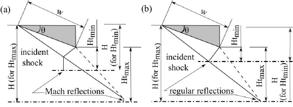
When a supersonic flow passes over symmetric wedges, a shock interaction/reflection occurs due to the flow turning. The shock reflection can be either a Mach reflection (MR) or a regular reflection (RR), depending on the flow parameters and wedge geometry. Figure 1 depicts the possible shock reflections between the maximum and minimum Ht values, which have been thoroughly investigated (Li & Ben-Dor, 1997). The Ht value depends on the wedge length w, wedge angle and the centre line distance H of the wedge leading edge, as shown in figures 1 (a) and (b). The shock reflection process is studied thoroughly by varying the wedge angle and flow Mach number. The wedge length is also an essential parameter, and based on the non-dimensionalized wedge length (w/H), we can classify wedges as long or short. As depicted in figure 3, most research on wedge flow focuses on long wedges where the expansion fan from the trailing edge does not interact with the incident shock wave. As shown in figure 3, the expansion fan will interact with the incident shock wave in the short wedges. Due to expansion fan interaction, the incident shock angle in short wedges decreases and curves continuously from the point where the leading expansion characteristic meets the shock wave to the triple/reflection point.
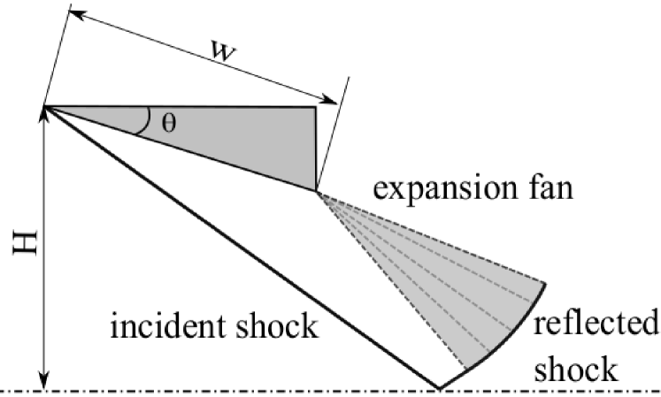
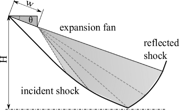
The curvature of the incident shock essentially depends on the extent of the expansion fan interaction. Consequently, the incident shock angle at the point of reflection will depend not only on the wedge angle and the flow Mach number but also on the w/H ratio. Any attempt to predict the shock transitions on short wedges must incorporate an accurate model of the incident shock curvature resulting from its interaction with the expansion fan.
1.1 Previous works in Shockwave- Expansion fan Interaction
The interactions of shock waves and expansion waves in one-dimensional flows are the subject of several investigations, in high-speed flows (Emanuel, 2001). A comprehensive description of the interactions of shock waves, expansion waves and contact surfaces, mainly in shock tube flows, can be seen by the work of Glass (1991). One of the early works in expansion fan shock wave interaction in symmetric wedge flows was carried out by Li & Ben-Dor (1996) in which an analytical solution was obtained for the curvature of the shock wave due to its interaction with a centered expansion wave of the opposite family. The curvature of the shock wave was approximated as a second-order polynomial. In the experimental and numerical validations of this analytical model (Nel et al., 2015), it was found that though the model prediction was accurate for small interactions, it could not predict the shock curvature for the stronger interactions. In another study (Hillier, 2007) on the shock-wave/expansion-wave interaction and the transition between regular and Mach reflections, analytical and numerical simulations were carried out to investigate the inviscid interactions of an expansion wave with an incident shock wave of the opposite family. The study was to stabilize a Mach reflection in a parallel duct for different flow conditions. Most of the analytical methods developed in shock reflections focused on predicting the MR configuration and the Mach stem height, a finite length scale in an MR in long wedges(Azevedo & Liu, 1993; Li & Ben-Dor, 1997; Mouton & Hornung, 2007). In these models, the slip line, which originates from the triple point in a Mach reflection, was assumed to be a straight line. Later, the refinement of the slip line curvature was carried out by (Bai & Wu, 2017), resulting in a better Mach stem prediction, as they considered the expansion waves generated over the slip line and its interaction with the transmitted expansion waves through the reflected shock. Further, numerical studies of a shock reflection in the presence of an upstream expansion wave and a downstream shock wave for two-dimensional flows by (Yao et al., 2013) reported that the expansion fan delayed the RRMR transition at lower Mach numbers (M=2 – 3.5) and expedited it at higher Mach numbers.
The analytical models discussed above were all for the interaction of the shock wave with the opposite (either right running or left running) family of expansion waves. On the contrary, in short wedges the incident shock is curved due to the prolonged interaction of the expansion wave of the same family. The study of this type of interaction is significant since the RRMR transition may solely depend on the incident shock angle at the reflection point, which is determined by the shock curvature due to the interaction. It is hence, essential to determine the parameters governing the shock angle at the reflection point and the change in transition criteria when these parameters vary. No works have been reported till date to investigate the short wedge effects in the RRMR transitions and the MR configurations, to the best of the authors’ knowledge. In the present investigation, an analytical model is hence developed to study the prolonged interaction of an expansion wave with an incident shock wave of the same family to predict the shock wave curvature. This is used to investigate the shock transitions in symmetric short wedges. The analytical model is validated with an in-house inviscid, 2D, structured finite volume solver with a fifth-order WENO scheme (Paramanantham et al., 2022). The RRMR transition lines are expected to be altered by the interactions of the expansion wave with the shock wave due to the small wedge lengths.
2 Shock wave expansion fan interaction - Analytical Modeling
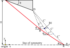
The shock–expansion interaction is modeled with the method of characteristics (MoC). The model assumptions are that the flow is steady, compressible, inviscid, two-dimensional (planar), isentropic, and rotational as it is a curved shock. The entropy is constant only along the streamlines. The basic configuration of the incident shock-expansion fan interaction model is shown in figure 2. The characteristic and compatibility equations for two-dimensional, isentropic, rotational, and supersonic flow are given below in Table 1.
The initial value line for the MOC is the first characteristic expansion line from the trailing edge (point D), which terminates at the intersection of the incident shock wave and the first expansion line (point B). The solution algorithm is initiated by giving a small increment of flow turn angle downstream from point D. The flow properties are determined using the Prandtl-Meyer relations. The C– curve from point D and C+ curve from point B intersect at point B1. The flow properties and location at point B1 are obtained by solving the above-mentioned characteristic and compatibility equations from B and D. The curved shock is obtained by solving discrete points on the shock. Since MoC is not valid across the shock, the solution point at the shock curvature is obtained by iteratively computing the local pressure ratio across the shock. Post-shock properties are calculated with the local incoming Mach number and the assumed pressure ratio across the shock. These flow properties should satisfy the compatibility equation along the C- curve originating from the interior point B1. The iterations stop when this condition is satisfied. The local shock angle is obtained, and the x and y positions of the curved shock are obtained by solving the characteristic equations. Subsequent points on the curved shock are obtained by incrementing the next flow turn angle at point D and repeating the above steps. One of the algorithms calculates the interior points in the flow field, while the other determines the discrete points along the shock curvature. and represents the shock angle and effective turn angle at the reflection point R respectively as shown in figure 4. The analytical model developed does not consider the possibility of Mach reflection and is valid only for regular reflection.
| Characteristic Equations | |
|---|---|
| (Streamline) | |
| (Right running characteristic line, ‘+’ subscript) | |
| (Left running characteristic line, ‘-’ subscript) | |
| Compatibility Equations | |
| (Streamline) | |
| (Streamline) | |
| (Right running characteristic Mach, ‘+’ subscript) | |
| (Left running characteristic line, ‘-’ subscript) |
3 Shockwave expansion fan interaction - Validation
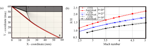
The validation of the analytical model with CFD is carried out by superimposing the curved shock locus of the analytical results and the computational results as shown in figure 5(a). It reveals that the analytical prediction agrees very well with the CFD results qualitatively. The same is done by varying the Mach number, w/H ratio and the wedge angle. The Mach number vs the non-dimensional shock reflection distance [shown in figure 2] (R/H) for different w/H ratios, obtained from analytical and CFD results are plotted. Figure 5(b) shows one such plot of Mach number vs R/H for the w/H ratio 0.33, for different wedge angles. It is seen that the maximum deviation between the analytical and CFD results is less than 2.
4 Results and Discussion
The transition of the shock reflection in a short wedge depends on the extent of the interaction of the expansion fan with the incident shock wave. Due to the interaction of the expansion fan, the incident shock is weakened, resulting in a decrease in the shock angle at the reflection point compared to the case where there is no interaction. Therefore, the transition angle between RR and MR is modified. The value of the shock angle at the point of reflection depends on the degree of interaction of the expansion fan, or the w/H ratio, while M and remain constant. As stated by Li & Ben-Dor (1997), the transition angle is typically determined using the detachment criterion for RRMR or the von Neumann criterion for MRRR. In the following sections, we will quantify the transition angles for the short wedges for various w/H ratios using the MoC method described in section 2 and validate these results with higher-order numerical simulations.
4.1 Transition lines- Detachment criterion validation
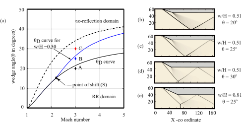
The delay in the transition criterion, specifically the detachment condition within the short wedge, can be attributed to the attenuation of the incident shockwave. The extent of the delay of this transition is determined by the w/H ratio. The determination of the detachment condition involves the solution of MoC for a specified Mach number (M), wedge angle (), and w/H. The detachment condition is generally shifted to higher wedge angles for the shorter wedges and ends at the no-reflection domain. Figure 6 (a) shows the shift in the detachment criterion for a w/H ratio of 0.5. The blue line represents the modified detachment criterion resulting from the interaction of the expansion fan with the incident shockwave, whereas the black solid line represents the detachment condition for long wedges in the absence of expansion fan interaction. Point S in figure 6 (a) depicts the beginning of the interaction between the expansion fan and the incident shock wave for a given w/H ratio. The deviation of the detachment condition occurs after this value, and for values below the interaction point, it remains the same as the long wedge. The transition line obtained from the MoC is validated with numerical simulations for M = 3 flow over a supersonic wedge; three cases are considered by keeping the Mach number constant and varying the wedge angle to comprehend the type of reflection obtained from the numerical simulations. The wedge angles are set to respectively (points A, B, and C in the figure 6(a)), and w/H is set to 0.5 (short wedge case) and 0.81 (long wedge case). Figures 6 (b-e) depict the numerical schlierens of the short wedge flow fields at points A, B, and C and the long wedge flow field simulation at point B. It can be seen from figures 6 (b-e) that the shock reflections correspond to points A and B are regular reflections, and C is the Mach reflection for the short wedge, while for point B, it is a Mach reflection for the long wedge. This confirms the shift of the transition line for a short wedge, making a regular reflection at point B, which was an erstwhile Mach reflection for the long wedge.
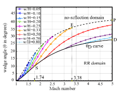
Figure 8 demonstrates that for all w/H ratios, a combination of M- exists for which the interaction begins, and the transition line shifts from that point (refer to figure 6 (a)). Figure 8 shows that w/H = 0.33 begins to deviate from the detachment condition line at point S, where M = 1.74 and . The shift ends at the no-reflection condition at point E corresponding to M = 3.38 and . For w/H = 0.33, the region under the curve SEPD will be RR, which eliminates MR flow configurations for any combination of Mach number and wedge angle beyond point E. Thus, the development of transition conditions for a shorter wedge has far-reaching implications as one can select a domain in which only a regular reflection occurs or control the size of the Mach reflection configuration by adjusting the w/H ratio.
4.2 Shock polar representation of the interaction effects
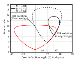
Figure 8 depicts the polar shock representation of a long and short wedge with a w/H ratio 0.33. The incoming flow has a Mach number of 3 and a wedge angle of 30∘. At the reflection point, the post-shock Mach number for a long wedge is 1.41, while it is 2.04 for a short wedge. The shock polar yields the MR solution corresponding to the long wedge and the RR solution corresponding to the short wedge. The shock polar reveals that the expansion fan interaction decreases the required flow turn angle at the reflection point in short wedges, even though the wedge angle remains unchanged.
4.3 Dual solution domain in short wedges
Another significant transition criterion in the wedge flows is the von Neumann criterion. Intuitively, it makes sense to assume that as the w/H ratio decreases, the von Neumann criterion line shifts towards higher wedge angles, similar to the detachment condition. The dual solution domain, the region between the detachment criterion line and the von Neumann criterion line, also undergoes this shift. In order to comprehend the change in the dual solution domain, transition lines for the von Neumann criterion were also drawn for various w/H ratios. The von Neumann criterion line for the short wedge is more complex than the detachment criterion, and the shift in the dual solution domain can be subdivided into three types based on the location of the von Neumann point B, which is the weak Mach reflection point as shown in figure 9 (a). We divided the shift in the dual solution domain into three categories as Type I, Type II, and Type III, which are discussed below.
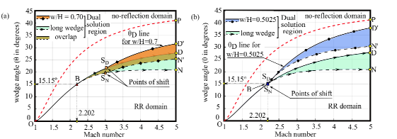
4.3.1 Type I Dual solution domain
In the type I domain, the von Neumann point ’B’ is identical to the long wedge flows, and the von Neumann criterion follows the long wedge von Neumann transition line prior to expansion fan interaction, shifting to higher wedge angles once expansion fan interaction commences. The von Neumann criterion () line and detachment criterion () line for w/H ratio 0.7 is shown in figure 9(a). The path OBSDD and OBSNN represents the and lines for long wedges. Both the transition lines follow the same path as that for a long wedge, up to the points of shift (SD and SN for the detachment line and von Neumann line, respectively), then follow a different path as (SD’ and SN’). For a short wedge, the path OBSDD’ and OBSNN’ represents the and line. The point of the shift of the line is at point SD, where M=3.03 and wedge angle 21.66∘, whereas the point of the shift of the line is at point SN, where M=3 and wedge angle 19.66∘. As the w/H value decreases from 0.7, the point of shifts SD and SN moves to the direction of the von Neumann point B, and merges with the point B, where M = 2.202, 15.15∘ and the w/H ratio is 0.5025 as shown in figure 9(b). Thus, short wedges with w/H ratios greater than 0.5025 will give a Type I dual solution domain. The characteristic of this type is that the weak Mach reflection or von Neumann point B remains the same for all w/H ratios greater than 0.5025 since both the points of shift from the detachment line and von Neumann line SD and SN occur after point B.
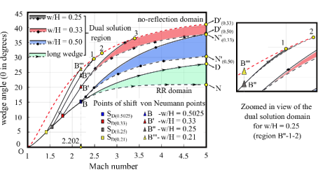
4.3.2 Type II Dual solution domain
As illustrated in figure 10, the type II dual solution domain occurs when the detachment condition occurs prior to the von Neumann point B for w/H ratios less than 0.5025. Consequently, the type II domain begins at w/H = 0.5025 and ends at w/H = 0.21, where the von Neumann point (B) reaches the no-reflection line (point B”’). The dual solution domains for w/H ratios 0.25, 0.33, 0.5025, and long wedge are shown in figure 10. In the figure, for the long wedges, paths OBD and OBN represent the and lines, respectively. Path OBD’(0.5), OBN’(0.5), represents the same for short wedge of w/H ratio 0.5025. For w/H ratio 0.33, the line and line follow the path OB’D’(0.33) and OB’N’(0.33) respectively as shown in figure 10. The detachment criterion line intersects the no-reflection line at point 3 and then follows the no-reflection line. A major part of the dual solution domain is between the no reflection line and the line. The line and line for w/H ratio 0.25 are shown as path OB”1 and OB”2, respectively. The dual solution domain for w/H=0.25 is extremely small, as seen in the zoomed-in picture in figure 10. The dual solution domain is hardly visible for wedges with w/H ratios less than 0.25. Thus for short wedges with w/H ratios less than 0.5025, the von Neumann point B shifts in the direction of the no-reflection domain and eventually meets the no-reflection line at point B”’, where the line of w/H ratio 0.21 intersects with the no-reflection line. Moreover, as the w/H value is reduced from 0.5025 to 0.21, the dual solution domain diminishes and shifts towards the no-reflection domain.
4.3.3 Type III Dual solution domain
The von Neumann solution does not exist for long wedges for Mach numbers less than 2.202, where the wedge angle 15.15∘. However, in short wedges, as the w/H ratio decreases, the wedge angle corresponding to the von Neumann point moves to higher wedge angles. The limiting factor to this shift in wedge angle is when von Neumann point intercepts the no-reflection line shown as point B”’ in figure 10. The value of the w/H ratio whose line passes exactly through this point B”’ will give the limiting point of von Neumann solutions in short wedges. The value calculated is very close to 0.21, neglecting the numerical errors. The line for w/H ratio 0.21 is shown in figure 10 as path OB”’, in which point SD(0.21) is the point of the shift from line, where M=1.44 and 5.3∘. The von Neumann point is at point B”’, where M=2.202 and wedge angle 25.93∘. Thus the parameter space where the value of w/H is less than 0.21 characterizes the type III domain. Type III domain differentiates itself from the other two domains as no dual solution domain exists in this type.
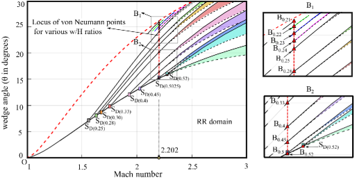
4.3.4 Locus of the von Neumann points
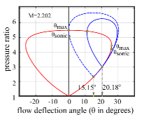
Shifting the von Neumann point is one of the defining characteristics of the short wedge flows. It is evident from the preceding discussion that for w/H ratios less than 0.5025, the von Neumann point moves, and figure 11 illustrates the locus of shift of the von Neumann points in the red dashed line for various w/H ratios. The red dashed line divides the region between the detachment and no-reflection lines into two distinct areas. Dual-domain solutions do not exist on the left side of the locus of the line, but they do exist on the right. The shift in von Neumann points in the parameter space follows a straight line passing through the X-intercept where M=2.202. Although the dual solution domain exists on the right side of the above-mentioned straight line, the domain close to this line is hardly visible due to the interaction effects, as shown in figure 11. To confirm the shift in von Neumann point B, shock polars of short wedges with actual wedge angle and effective wedge angle(turn angle at reflection point) are drawn. Figure 12 shows the shock polar for w/H ratio 0.33 at the von Neumann point B0.33 (refer figure 11). The solid blue line indicates r-polar for the actual wedge angle used, and the dashed blue line shows the same for the effective wedge angle at the reflection point R(refer figure 2). At point B0.33, the wedge angle is 20.18∘ and due to interaction this is reduced to 15.15∘. Thus the von Neumann shift in short wedge flows is validated with the shock polars. Further investigations are required to comprehend the shock reflection configurations and the flow behaviour in Type I, Type II and Type III interactions in the flow over short wedges.
5 Conclusion
The shock reflection phenomena on short wedges have been investigated analytically and computationally. The interaction of the expansion fan emanating from the trailing edge of the short wedge with the incident shock wave is found to curve the incident shock. The curving of the incident shock wave leads to the change of shock angle at the reflection/triple point, consequently leading to a shift in the transition line. The transition lines plotted for different w/H ratios from 0.05 to 0.8 show that the shift in transition lines depends on the extent of interaction. The plot is useful in finding the detachment/von Neumann criterion for any Mach number between 1 and 5 for a particular w/H ratio. Moreover, we can control the appearance of MR or its configuration, for a particular Mach number by selecting the suitable (w/H) ratio from the transition lines generated. As the extent of expansion fan interaction with the incident shock increases, the dual domain shifts its location and diminishes as a function of w/H ratio facilitating the control of the MRRR hysteresis process.
References
- Azevedo & Liu (1993) Azevedo, D. J. & Liu, Ching Shi 1993 Engineering approach to the prediction of shock patterns in bounded high-speed flows. AIAA Journal 31 (1), 83–90, arXiv: https://doi.org/10.2514/3.11322.
- Bai & Wu (2017) Bai, Chen-Yuan & Wu, Zi-Niu 2017 Size and shape of shock waves and slipline for mach reflection in steady flow. Journal of Fluid Mechanics 818, 116–140.
- Emanuel (2001) Emanuel, George 2001 Chapter 3.1 - shock waves in gases. In Handbook of Shock Waves, Vol-1 (ed. G BEN-DOR, O IGRA & T ELPERIN), pp. 185–262. Burlington: Academic Press.
- Glass (1991) Glass, I. I. 1991 Over forty years of continuous research at utias on nonstationary flows and shock waves. Shock Waves 1 (1), 75–86.
- Hillier (2007) Hillier, R. 2007 Shock-wave/expansion-wave interactions and the transition between regular and mach reflection. Journal of Fluid Mechanics 575, 399–424.
- Li & Ben-Dor (1996) Li, H. & Ben-Dor, G. 1996 Oblique-shock/expansion-fan interaction - analytical solution. AIAA Journal 34 (2), 418–421, arXiv: https://doi.org/10.2514/3.13081.
- Li & Ben-Dor (1997) Li, H. & Ben-Dor, G. 1997 A parametric study of mach reflection in steady flows. Journal of Fluid Mechanics 341, 101–125.
- Mouton & Hornung (2007) Mouton, Christopher A. & Hornung, Hans G. 2007 Mach stem height and growth rate predictions. AIAA Journal 45 (8), 1977–1987, arXiv: https://doi.org/10.2514/1.27460.
- Nel et al. (2015) Nel, Lara, Skews, Beric & Naidoo, Kavendra 2015 Schlieren techniques for the visualization of an expansion fan/shock wave interaction. Journal of Visualization 18 (3), 469–479.
- Paramanantham et al. (2022) Paramanantham, Vinoth, Janakiram, Sushmitha & Gopalapillai, Rajesh 2022 Prediction of mach stem height in compressible open jets. part 1. overexpanded jets. Journal of Fluid Mechanics 942, A48.
- Yao et al. (2013) Yao, Y., Li, S. G. & Wu, Z. N. 2013 Shock reflection in the presence of an upstream expansion wave and a downstream shock wave. Journal of Fluid Mechanics 735, 61–90.