Measurement of the decay of laser-driven linear plasma wakefields
Abstract
We present the first measurements of the temporal decay rate of one-dimensional, linear Langmuir waves excited by an ultra-short laser pulse. Langmuir waves with relative amplitudes of approximately were driven by , laser pulses in hydrogen and deuterium plasmas of density . The wakefield lifetimes were measured to be ps and ps respectively for hydrogen and deuterium. The experimental results were found to be in good agreement with 2D particle-in-cell simulations. In addition to being of fundamental interest, these results are particularly relevant to the development of laser wakefield accelerators (LWFAs) and wakefield acceleration schemes using multiple pulses, such as multi-pulse laser wakefield accelerators (MP-LWFAs).
I Introduction
Next-generation plasma wakefield particle accelerators use charged beams or laser pulses to excite Langmuir waves that can support accelerating gradients on the order of GeV/cm [1]. Considerable progress has been made in this sphere in recent years, including, for example: the acceleration to multi-GeV-scale energies in wakefields driven by laser pulses [2, 3], electron bunches [4, 5], and by long proton bunches [6]; and applications of plasma-accelerated beams to the generation of radiation [7], and the first demonstrations of gain in free-electron-laser experiments [8, 9].
In the original concept [1] of a laser-driven plasma accelerator, the driving laser pulse had a duration shorter than the plasma period , where , and in which is the electron charge, is the electron mass, and is the vacuum permittivity. Many important results have been obtained in this regime, for both laser- and particle-beam-driven plasma accelerators, and this regime continues to be a major focus of research worldwide. However, it is also possible to drive the plasma wakefield with: (i) a train of short drive pulses, spaced by ; or (ii) by a drive pulse that is long compared to , but with a temporal intensity profile that is modulated with a period of [10, 11, 4, 6, 12].
We recently extended this latter concept by proposing a new method [13] for generating the required pulse train: frequency modulation of a long laser pulse by a plasma wave driven by a short, low-energy seed pulse, followed by temporal compression in a dispersive optical system. Simulations of this scheme show that electrons could be accelerated to in a plasma stage driven by a pulse train generated by a , drive pulse of the type which could be provided by a kilohertz repetition rate thin-disk laser [14]. For plasma accelerators driven by long () drivers, it is important to understand the extent to which the amplitude of the plasma wave decays over the total duration of the driver.
Theoretical studies of plasma dynamics have shown that interactions between the oscillating electrons and the background ions can lead to the growth of instabilities which dissipate the Langmuir wave energy into higher-order daughter waves [15]. Ultimately, these instabilities lead to the decay of the wakefields and heating of the plasma. In this paper, we present the results of an experimental investigation of the wakefield decay rate in a parameter regime that is relevant for several current and future plasma acceleration schemes, such as plasma wakefield acceleration (PWFA) [6], laser wakefield acceleration (LWFA) [2] and multi-pulse laser wakefield acceleration (MP-LWFA) [10]. We compare our measured results with particle-in-cell simulations, and show that there is good agreement between theory, simulations, and measurements.
| Regime | Target | Plasma | / | / eV | [ps] | Ref | ||||||
|---|---|---|---|---|---|---|---|---|---|---|---|---|
| LBWA | Cell | D2 | [16] | |||||||||
| SM-LWFA | Jet | He | [17] | |||||||||
| SM-LWFA | Jet | He | [18] | |||||||||
| SM-LWFA | Jet | H2 | [19] | |||||||||
| SM-LWFA | Jet | He | [19] | |||||||||
| LWFA | Cell | He | [20] | |||||||||
| LWFA | Jet | He | [21] | |||||||||
| LWFA | Cell | H2 | This work | |||||||||
| LWFA | Cell | D2 | This work |
We first establish the key laser and plasma parameters which determine the regime in which a laser-plasma accelerator operates. When the quiver velocity of the plasma electrons in the field of the driving laser is non-relativistic, the wakefield is approximately sinusoidal, and is said to be in the linear regime. For a single, short driving laser pulse, this corresponds to a peak normalised vector potential , where , the laser electric field strength, and the laser frequency. In this regime, and for the case of a driving laser pulse with Gaussian temporal and transverse intensity profiles, the relative amplitude of the plasma wave is given by the sum of the of the relative amplitudes of the radial and longitudinal wakefields [20],
| (1) | ||||
| (2) |
where is the radial distance from the propagation axis of the drive laser, is the temporal delay after the peak of the drive pulse, is the plasma frequency, is the plasma electron density, is the critical density, and , , and are respectively the angular frequency, beam radius at the intensity, the duration (defined as the half width at intensity) and peak intensity of the driving laser pulse. The ratio of the radial to the longitudinal wakefield components at is , where indicates a predominantly radial wakefield and indicates a longitudinal wakefield, which we will refer to as a one-dimensional wakefield.
The mechanisms responsible for the decay of laser-driven plasma waves have been investigated in several earlier studies. Marquès et al. [20] found that radial-dominated and longitudinal-dominated wakefields can have different decay mechanisms. Longitudinal wakefields decay through collisions [22], Landau damping [23], beam loading by accelerated particles [17], and the modulational instability [15]. The growth rate of the modulational instability is expected to be much greater than the collisional or Landau damping mechanisms, and hence will usually dominate the decay in the case when beam-loading is not significant. If the total charge trapped and accelerated by the wakefield is large, then beam loading becomes important, and can be the leading cause of the wakefield decay [17]. Radial wakefields can decay via an additional mechanism. When the radial plasma density is non-uniform, electrons at different radial trajectories have different oscillation periods, which leads to a loss of coherence of the plasma oscillation. This can happen e.g. via a final radial extent of the drive laser or beam, or in pre-formed plasma channels [24, 25, 26, 27].
In addition to the ratio , two other parameters are important in determining the mechanisms responsible for, and the rate of, wakefield decay. First, the ratio of the energy density of the Langmuir wave to the thermal energy density, , where , , is the electric field strength of the wakefield, is the Boltzmann constant, and is the electron plasma temperature [15]. The parameter determines the growth rate of the modulational instability and delineates the strong-field regime () from the weak-field regime (). Second, the ratio of the drive pulse length to the plasma ion period , where , where , and in which and are the charge and mass of the ions respectively. For the plasma instabilities driven by ion dynamics co-evolve with the drive laser, and for they develop only after the wakefield is excited.
Table I summarises the results of previous measurements of the decay time of laser-driven wakefields. The penultimate and antepenultimate columns of the table give the wakefield decay time and the ratio of this to the electron plasma period . It should be noted that the precise definition of varies between the experiments. In Refs. [19, 16] it refers to the total length of the detectable wakefield signal, whereas in Refs. [20, 21, 17, 18], and in the present work, it refers to the time taken for the wakefield amplitude to decay to of the maximum amplitude. We also note that the time given in Ref [16] refers to the saturation time of the beatwave-driven wakefield, and, for simplicity, we have taken this to be equal to the decay time. It is striking that with the exception of Ref. [21], the ratio of the wakefield lifetime to the electron plasma period varies by less than a factor of 5 in experiments for which the plasma density and the duration of the drive pulse both vary by more than two orders of magnitude.
The earlier work summarised in Table I was undertaken in a wide range of laser-plasma accelerator regimes. In the experiment by Moulin et al. [16] a wakefield was excited using the ‘beatwave’ (LBWA) scheme in which two long pulses ( and ), of angular frequencies and , interfere to generate a beat pattern at the plasma frequency . In that work plasma instabilities therefore developed during the excitation of the wakefield by the drive beam or drivers. The experiments by Leblanc et al. [17], Chen et al. [18], and Ting et al. [19] corresponded to the self-modulated laser wakefield (SM-LWFA) regime in which interaction between a long laser pulse () and the weak plasma wave it drives causes the laser pulse to become modulated with a period of , leading to a nonlinear feedback in which the modulation of the laser pulse and the wakefield amplitude both increase with delay relative to the front of the driving pulse. Hence these experiments correspond to an intermediate regime in which the duration of the drive pulse lies between the electron plasma period and the ion plasma period . Finally, Marquès et al. [20] and Kotaki et al. [21] performed experiments in the LWFA regime originally proposed by Tajima and Dawson, in which the wakefield is excited by a laser pulse with . These last two experiments both operated in the radial-dominated wakefield regime, and shorter decay times relative to the plasma period were observed compared to the experiments that generated longitudinal-dominated wakefields. With the exception of the work by Kotaki et al. [21], in all the experiments , i.e. they were all conducted in the linear wakefield regime. It is noteworthy that for the much stronger wakefields () studied in [21], the observed ratio is much smaller than found in experiments operating in the linear regime.
Before concluding this short review of prior experimental work, we note that wakefield decay and ion motion has also been studied for proton-beam-driven wakefield accelerators [28]; these results have not been included in Table I owing to the very different driver and plasma parameters. We also note recent experiments to establish the limits to the repetition rate of PWFAs driven by electron bunches [29]. The topic of the present paper, the time-scale for wakefield decay, is related to the maximum possible repetition rate of a plasma accelerator. However, we emphasize that wakefield decay is just the first step in a complex chain of processes — that includes wakefield decay, electron-ion recombination, and heat redistribution — that must be completed before the following drive pulse can be delivered.
To our knowledge, the new work presented in the present paper is the first measurement of the decay rate of a one-dimensional (), linear wakefield () in the short-pulse LWFA regime (). This short-pulse regime is relevant for future plasma wakefield facilities [30, 31, 32] (although we note that some of these are expected to operate in the quasi-linear regime ( for a single pulse) e.g. [30]), and it is also relevant to alternative schemes, such as MP-LWFAs [10, 11, 13].
II Measurement of the wakefield lifetime
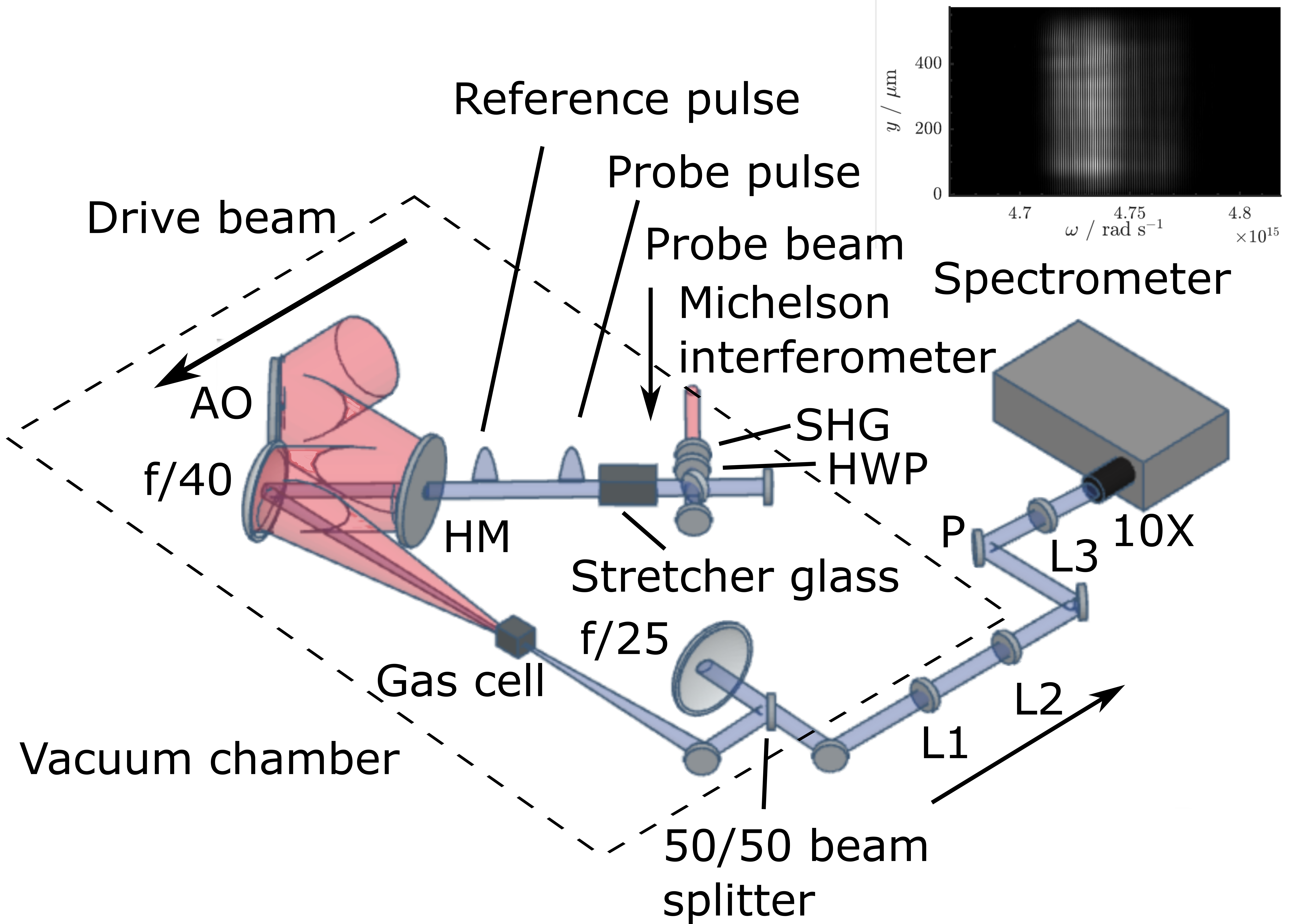
Experiments to measure the lifetime of a plasma wakefield in the 1D, linear regime were undertaken at the Central Laser Facility of the Rutherford Appleton Laboratory, using the Astra-Gemini TA3 laser. A schematic illustration of the experiment layout is shown in Fig. 1.
A linearly polarised laser pulse with energy , centre wavelength , and FWHM pulse duration was used to drive the wakefield. This pulse was focused by an on-axis reflecting paraboloid of focal length , used at , to a spot size ( intensity radius) of at the centre of a gas cell. The peak intensity at the laser focus was , corresponding to a peak normalised vector potential of , with approximately a factor of of the beam energy enclosed within the FWHM beam diameter at focus.
Laser radiation could enter and leave the cell via a pair of coaxial, diameter pinholes located at each end of the long gas cell. Gas, either hydrogen (H2) or deuterium (D2), was flowed into the cell in a pulse of duration of approximately ms; the gas flowed into the surrounding vacuum chamber via the pinholes. For these experiments the cell backing pressure was , corresponding to an electron density (assuming % ionization).
The amplitude of the plasma wave was measured by frequency domain holography (FDH) [33], analysed with the TESS technique [34, 35]. In this method, two chirped and stretched diagnostic pulses are generated: (i) a probe pulse, which propagates behind the drive pulse, and acquires a temporally-dependent phase shift from the density modulation of the plasma wave; and (ii) a near-identical reference pulse, which propagates ahead of the drive pulse. This pair of diagnostic pulses was generated by passing a frequency-doubled pick-off from the probe beam through a Michelson interferometer with a path difference corresponding to . Each of the pair of pulses thereby created was then frequency-chirped and stretched to a duration of by propagating them through a mm long piece of glass (BK7). The diagnostic pulses were injected coaxially with the drive beam by directing them through a holed turning mirror, and focused into the gas cell by the same optic used to focus the drive beam. On leaving the gas cell the diagnostic pulses were separated from the transmitted drive pulse by reflection from a dichroic mirror and imaged onto the entrance slit of a Czerny-Turner spectrometer to yield a spectral interferogram which was recorded by a CCD camera (Andor Newton DU940N-BU). The wakefield amplitude was calculated from the captured interferograms using the TESS technique, as follows. Each spectral interferogram was Fourier transformed along its spectral axis to give a spatio-temporal profile. The Fourier-transformed data comprises a zero-frequency (“DC”) band; a sideband located at ; and three satellites — two either side of the sideband, and a third located near the DC band. These satellites arise from the phase-shift imposed on the probe beam by the sinusoidal plasma wave. The satellites are offset from the sideband and have temporal locations given by [34, 35],
| (3) |
where is the group delay dispersion (GDD) of the probe and reference pulses. For plasma waves with large amplitudes, higher-order satellites can appear, located at , , but these higher-order satellites were not observed in this experiment. The relative amplitude of the wakefield at delay can be found from the ratio of the satellite amplitude to that of the sideband since this is given by [34, 35],
| (4) |
where,
| (5) |
and where and are Bessel functions of the first kind, a spectral overlap function (see Supplemental Material [36]), is the interaction length, and is the frequency of the probe laser. By varying the backing pressure, and measuring immediately after the drive pulse, it was found that the pressure in the cell was linearly related to the measured backing pressure through , where accounts for the fact that the pressure guage was located prior to the gas cell gas inlet and mbar (see Supplemental Material [36]).
III Results
The wakefield amplitude was measured for a range of delays in steps of . For each temporal delay, the results of 10 shots were averaged in order to reduce the statistical error in the measured wake amplitude.
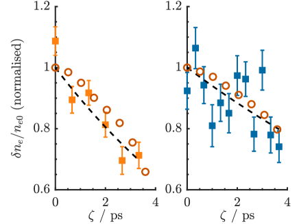
Fig. 2 shows, for hydrogen and deuterium, the measured wakefield amplitude as a function of delay, normalised to , where is determined by a fit of the function to the data. Due to variations in the experimental conditions, the plasma waves driven in deuterium had an initially lower amplitude, which made the error bars relatively larger after normalisation.
Also shown in Fig. 2 are the results of 2D particle-in-cell (PIC) simulations performed with the relativistic particle-in-cell code smilei [Simulation of Matter Irradiated by Light at Extreme Intensities, 37] for the laser and plasma parameters used in the experiment (see Supplemental Material). The wakefield amplitude was calculated from the maximum Fourier amplitude (near ) of the density variation corresponding to the wakefield plasma oscillation, where is the ion density. The Fourier amplitude, , was converted to the wakefield amplitude, using the relation . Here is a Tukey window with window parameter (set to =0.2), and , the simulation cell size in the dimension along the laser axis of propagation.
The results of the simulations are seen to be in very good agreement with the experimental data. As well as correctly reproducing the timescale of the wakefield decay, the wakefield amplitudes calculated by the simulations are found to be close in absolute terms to the measured values. For both hydrogen and deuterium plasmas the relative wake amplitude at was calculated to be % for the laser and plasma conditions of the experiment. This compares with the measured values of % for hydrogen and % for deuterium. This agreement, which is within a factor of two, is remarkably good when it is considered that: (i) the simulations contained no free parameters; and (ii) the measured wakefield amplitude is rather sensitive to variations in many of the experimental parameters. These experimental parameters include: the pulse energy, duration, and spatio-temporal quality of the laser pulse; the spectrum of the probe pulse; the relative alignment of the drive and diagnostic pulses; and the pressure in the gas cell.
Table II summarises the results of the measurements and simulations; to enable a comparison with the experiments, the temporal variation of the wake amplitude found in the simulations was fitted to an exponential decay. For the conditions of the experiment we find: for hydrogen, , corresponding to around 76 plasma periods; for deuterium these values are approximately and 134 periods respectively.
The measured wakefield lifetimes are long compared to the electron plasma period , and are comparable to the ion plasma periods and for hydrogen and deuterium respectively. The ratios of the decay times measured for deuterium and hydrogen are found to be and from the measurements and simulations respectively. The experimentally measured decay times are seen to be in very close agreement with those determined from PIC simulations. Unfortunately the experimental errors, particularly those for , are too large to conclude that the ratio differs from unity. However, the PIC simulations do show that the decay time for deuterium is longer than that for hydrogen, and that their ratio is close to, but larger than, the ratio of the ratio of the inverse ion plasma frequencies . The measurements and simulations demonstrate that the wake decay time is of the order of the inverse ion plasma period, but that it is too simplistic to assume that the decay time is strictly proportional to this quantity [38].
A detailed analysis of the PIC simulations [38], and comparison with work by Sanmartin et al [39], shows plasma waves in these experiments decay via the modulational instability. This instability causes small spatial variations in the ion density to grow exponentially, with a time-scale of order , leading to a loss of coherence of the electron oscillations, and hence decay of the wakefield amplitude.
| / | |||
|---|---|---|---|
| Experiment | |||
| Simulation |
IV Conclusion
In conclusion, we have used single-shot frequency domain holography to measure the lifetime of 1D linear plasma wakefields in hydrogen and deuterium plasmas driven in the short-pulse LWFA regime. Wakefields with relative amplitudes of approximately were driven by , laser pulses in hydrogen and deuterium plasmas of density . The wakefield lifetimes were measured to be ps and ps respectively for hydrogen and deuterium. The experimental results were found to be in very good agreement with 2D particle-in-cell simulations.
These findings are of relevance to the MP-LWFA scheme, in which the wakefield is driven resonantly by a train of short pulses [10, 11]. This latter approach is of considerable interest since it offers a route to driving LWFAs at high pulse repetition rates with novel laser technologies which can provide the required average power, with high wall-plug efficiency, but which deliver pulses which are too long to drive a plasma wave directly. The wakefield lifetime is of key importance to the MP-LWFA scheme since it determines the maximum useful number of pulses in the pulse train. The work presented here shows that, for plasma densities relevant to MP-LWFAs, the wakefield lifetime corresponds to of order 100 plasma periods, which is large compared to the pulses required for MP-LWFA schemes driven by pulse trains of total duration in the picosecond range [13].
V Acknowledgements
This work was supported by the UK Science and Technology Facilities Council (STFC UK) [grant numbers ST/N504233/1, ST/P002048/1, ST/R505006/1, ST/S505833/1, ST/V001655/1]; the Engineering and Physical Sciences Research Council [EP/N509711/1, EP/V006797/1], and the Central Laser Facility. This material is based upon work supported by the Air Force Office of Scientific Research under award number FA9550-18-1-7005. This work was supported by the European Union’s Horizon 2020 research and innovation programme under grant agreements No. 653782 and 730871.
This research was funded in whole, or in part, by EPSRC and STFC, which are Plan S funders. For the purpose of Open Access, the author has applied a CC BY public copyright licence to any Author Accepted Manuscript version arising from this submission.
The data associated with this paper, and the input decks used for the PIC simulations are available at https://zenodo.org/deposit/7945414
References
- Tajima and Dawson [1979] T. Tajima and J. M. Dawson, Laser electron accelerator, Phys. Rev. Lett. 43, 267 (1979).
- Leemans et al. [2006] W. P. Leemans, B. Nagler, A. J. Gonsalves, C. Tóth, K. Nakamura, C. G. R. Geddes, E. Esarey, C. B. Schroeder, and S. M. Hooker, GeV electron beams from a centimetre-scale accelerator, Nature Physics 2, 696 (2006).
- Gonsalves et al. [2019] A. J. Gonsalves, K. Nakamura, J. Daniels, C. Benedetti, C. Pieronek, T. C. H. D. Raadt, S. Steinke, J. H. Bin, S. S. Bulanov, J. V. Tilborg, C. G. R. Geddes, C. B. Schroeder, C. Tóth, E. Esarey, K. Swanson, G. Bagdasarov, N. Bobrova, V. Gasilov, G. Korn, P. Sasorov, and W. P. Leemans, Petawatt laser guiding and electron beam acceleration to 8 GeV in a laser-heated capillary discharge waveguide, Physical Review Letters 122, 84801 (2019).
- Yakimenko et al. [2019] V. Yakimenko, L. Alsberg, E. Bong, G. Bouchard, C. Clarke, C. Emma, S. Green, C. Hast, M. J. Hogan, J. Seabury, N. Lipkowitz, B. O’Shea, D. Storey, G. White, and G. Yocky, FACET-II facility for advanced accelerator experimental tests, Physical Review Accelerators and Beams 22, 101301 (2019).
- Pompili et al. [2021] R. Pompili, D. Alesini, M. P. Anania, M. Behtouei, M. Bellaveglia, A. Biagioni, F. G. Bisesto, M. Cesarini, E. Chiadroni, A. Cianchi, G. Costa, M. Croia, A. Del Dotto, D. Di Giovenale, M. Diomede, F. Dipace, M. Ferrario, A. Giribono, V. Lollo, L. Magnisi, M. Marongiu, A. Mostacci, L. Piersanti, G. Di Pirro, S. Romeo, A. R. Rossi, J. Scifo, V. Shpakov, C. Vaccarezza, F. Villa, and A. Zigler, Energy spread minimization in a beam-driven plasma wakefield accelerator, Nature Physics 17, 499 (2021).
- Adli et al. [2018] E. Adli, A. Ahuja, O. Apsimon, R. Apsimon, D. Barrientos, F. Batsch, J. Bauche, M. Bernardini, T. Bohl, C. Bracco, G. Burt, A. Caldwell, M. Cascella, J. Chappell, E. Chevallay, M. Chung, D. Cooke, H. Damerau, L. Deacon, L. H. Deubner, A. Dexter, S. Doebert, R. Fiorito, R. A. Fonseca, F. Friebel, L. Garolfi, S. Gessner, I. Gorgisyan, A. A. Gorn, J. Farmer, E. Granados, O. Grulke, E. Gschwendtner, J. Hansen, A. Helm, J. R. Henderson, M. Ibison, L. Jensen, L. M. Brun, M. Martyanov, S. Jolly, F. Keeble, F. Kraus, Y. Li, S. Liu, N. Lopes, J. Mitchell, J. C. Molendijk, J. T. Moody, M. Moreira, S. Mazzoni, D. M. Godoy, C. Pasquino, A. Pardons, K. Pepitone, A. Perera, A. Petrenko, S. Pitman, A. Pukhov, S. Rey, L. O. Silva, L. Soby, R. Speroni, K. Rieger, H. Ruhl, J. S. Schmidt, I. A. Shalimova, M. Turner, F. Velotti, L. Verra, J. Vieira, B. Williamson, R. I. Spitsyn, M. Wing, B. Woolley, and G. Xia, Acceleration of electrons in the plasma wakefield of a proton bunch, Nature 561, 4 (2018).
- Albert et al. [2017] F. Albert, N. Lemos, J. L. Shaw, B. B. Pollock, C. Goyon, W. Schumaker, A. M. Saunders, K. A. Marsh, A. Pak, J. E. Ralph, J. L. Martins, L. D. Amorim, R. W. Falcone, S. H. Glenzer, J. D. Moody, and C. Joshi, Observation of Betatron X-Ray Radiation in a Self-Modulated Laser Wakefield Accelerator Driven with Picosecond Laser Pulses, Physical Review Letters 118, 134801 (2017).
- Wang et al. [2021] W. Wang, K. Feng, L. Ke, C. Yu, Y. Xu, R. Qi, Y. Chen, Z. Qin, Z. Zhang, M. Fang, J. Liu, K. Jiang, H. Wang, C. Wang, X. Yang, F. Wu, Y. Leng, J. Liu, R. Li, and Z. Xu, Free-electron lasing at 27 nanometres based on a laser wakefield accelerator, Nature 595, 516 (2021).
- Ferrario [2022] M. Ferrario, Accepted for publication, Nature 605, 659 (2022).
- Hooker et al. [2014] S. M. Hooker, R. Bartolini, S. P. D. Mangles, A. Tünnermann, L. Corner, J. Limpert, A. Seryi, and R. Walczak, Multi-pulse laser wakefield acceleration: a new route to efficient, high-repetition-rate plasma accelerators and high flux radiation sources, Journal of Physics B: Atomic, Molecular and Optical Physics 47, 234003 (2014).
- Cowley et al. [2017] J. Cowley, C. Thornton, C. Arran, R. J. Shalloo, L. Corner, G. Cheung, N. H. Matlis, D. R. Symes, R. Walczak, and S. M. Hooker, Excitation and Control of Plasma Wakefields by Multiple Laser Pulses, Physical Review Letters 119, 044802 (2017).
- Muggli et al. [2010] P. Muggli, B. Allen, V. E. Yakimenko, J. Park, M. Babzien, K. P. Kusche, and W. D. Kimura, Simple method for generating adjustable trains of picosecond electron bunches, Physical Review Special Topics - Accelerators and Beams 13, 1 (2010).
- Jakobsson et al. [2021] O. Jakobsson, S. M. Hooker, and R. Walczak, Gev-scale accelerators driven by plasma-modulated pulses from kilohertz lasers, Phys. Rev. Lett. 127, 184801 (2021).
- Tünnermann et al. [2010] A. Tünnermann, T. Schreiber, and J. Limpert, Fiber lasers and amplifiers: An ultrafast performance evolution, Applied Optics 49, 71 (2010).
- Mora et al. [1988] P. Mora, D. Pesme, A. Heron, G. Laval, and N. Silvestre, Modulational Instability and Its Consequences for the Beat-Wave Accelerator, Physical Review Letters 61, 1611 (1988).
- Moulin et al. [1994] F. Moulin, F. Amiranoff, M. Laberge, J. R. Marquès, B. Cros, G. Matthieussent, D. Bernard, F. Jacquet, P. Miné, A. Specka, C. Stenz, and P. Mora, Coupling between electron and ion waves in Nd-laser beat-wave experiments, Physics of Plasmas 1, 1318 (1994).
- Blanc et al. [1996] S. P. L. Blanc, M. C. Downer, R. Wagner, S. Chen, A. Maksimchuk, G. Mourou, and D. Umstadter, Temporal Characterization of a Self-Modulated Laser Wakefield, Physical Review Letters 77, 5381 (1996).
- Chen et al. [2000] S. Y. Chen, M. Krishnan, A. Maksimchuk, and D. Umstadter, Excitation and damping of a self-modulated laser wakefield, Physics of Plasmas 7, 403 (2000).
- Ting et al. [1996] A. Ting, K. Krushelnick, C. I. Moore, H. R. Burris, E. Esarey, J. Krall, and P. Sprangle, Temporal Evolution of Self-Modulated Laser Wakefields Measured by Coherent Thomson Scattering, Physical Review Letters , 5377 (1996).
- Marques et al. [1997] J. R. Marques, F. Dorchies, F. Amiranoff, P. Audebert, J. C. Gauthier, J. P. Geindre, A. Antonetti, J. T. M. Antonsen, P. Chessa, and P. Mora, Laser wakefield: experimental study of nonlinear radial electron oscillations, Physics of Plasmas 1162, 1162 (1997).
- Kotaki et al. [2002] H. Kotaki, M. Kando, T. Oketa, S. Masuda, J. K. Koga, S. Kondo, S. Kanazawa, T. Yokoyama, T. Matoba, and K. Nakajima, Direct measurement of coherent ultrahigh wakefields excited by intense ultrashort laser pulses in a gas-jet plasma, Physics of Plasmas 9, 1392 (2002).
- Banks et al. [2016] J. W. Banks, S. Brunner, R. L. Berger, and T. M. Tran, Vlasov simulations of electron-ion collision effects on damping of electron plasma waves, Physics of Plasmas 23, 032108 (2016).
- Bellan [2006] P. M. Bellan, Fundamentals of plasma physics (Cambridge University Press, 2006).
- Shalloo et al. [2019] R. Shalloo, C. Arran, A. Picksley, A. von Boetticher, L. Corner, J. Holloway, G. Hine, J. Jonnerby, H. Milchberg, C. Thornton, R. Walczak, and S. Hooker, Low-density hydrodynamic optical-field-ionized plasma channels generated with an axicon lens, Physical Review Accelerators and Beams 22, 041302 (2019).
- Picksley et al. [2020a] A. Picksley, A. Alejo, J. Cowley, N. Bourgeois, L. Corner, L. Feder, J. Holloway, H. Jones, J. Jonnerby, H. Milchberg, L. Reid, A. Ross, R. Walczak, and S. Hooker, Guiding of high-intensity laser pulses in 100-mm-long hydrodynamic optical-field-ionized plasma channels, Physical Review Accelerators and Beams 23, 081303 (2020a).
- Picksley et al. [2020b] A. Picksley, A. Alejo, R. J. Shalloo, C. Arran, A. von Boetticher, L. Corner, J. A. Holloway, J. Jonnerby, O. Jakobsson, C. Thornton, R. Walczak, and S. M. Hooker, Meter-scale conditioned hydrodynamic optical-field-ionized plasma channels, Physical Review E 102, 053201 (2020b).
- Alejo et al. [2022] A. Alejo, J. Cowley, A. Picksley, R. Walczak, and S. Hooker, Demonstration of kilohertz operation of hydrodynamic optical-field-ionized plasma channels, Physical Review Accelerators and Beams 25, 011301 (2022).
- Vieira et al. [2012] J. Vieira, R. A. Fonseca, W. B. Mori, and L. O. Silva, Ion motion in self-modulated plasma wakefield accelerators, Phys. Rev. Lett. 109, 145005 (2012).
- D’Arcy et al. [2022] R. D’Arcy, J. Chappell, J. Beinortaite, S. Diederichs, G. Boyle, B. Foster, M. J. Garland, P. G. Caminal, C. A. Lindstrøm, G. Loisch, S. Schreiber, S. Schröder, R. J. Shalloo, M. Thévenet, S. Wesch, M. Wing, and J. Osterhoff, Recovery time of a plasma-wakefield accelerator, Nature 603, 58 (2022).
- Assmann et al. [2019] R. Assmann, M. Weikum, and T. Akhter, EuPRAXIA Conceptual Design Report (Draft), European Physical Journal 4284, 3675 (2019).
- Cros et al. [2019] B. Cros, P. Muggli, C. Schroeder, S. Hooker, P. Piot, J. England, S. Gessner, J. Vieira, E. Gschwendtner, J.-L. Vay, and M. Peskin, Towards an Advanced Linear International Collider, Arxiv (pre-print) , 1901.1037 (2019).
- Leemans et al. [2010] W. P. Leemans, R. Duarte, E. Esarey, S. Fournier, C. G. Geddes, D. Lockhart, C. B. Schroeder, C. Toth, J. L. Vay, and S. Zimmermann, The Berkeley lab laser accelerator (BELLA): A 10 GeV laser plasma accelerator, AIP Conference Proceedings 1299, 3 (2010).
- Matlis et al. [2006] N. H. Matlis, S. Reed, S. S. Bulanov, V. Chvykov, G. Kalintchenko, T. Matsuoka, P. Rousseau, V. Yanovsky, A. Maksimchuk, S. Kalmykov, G. Shvets, and M. C. Downer, Snapshots of laser wakefields, Nature Physics 2, 749 (2006).
- Matlis et al. [2016] N. Matlis, A. Maksimchuk, V. Yanovsky, W. Leemans, and M. Downer, Analysis of sinusoidally modulated chirped laser pulses by temporally encoded spectral shifting, Optics Letters 41, 1 (2016).
- Arran et al. [2018] C. Arran, N. H. Matlis, R. Walczak, and S. M. Hooker, Reconstructing nonlinear plasma wakefields using a generalized temporally encoded spectral shifting analysis, Physical Review Accelerators and Beams 21, 1 (2018).
- Jonnerby et al. [2023] J. Jonnerby, A. v. Boetticher, J. Holloway, L. Corner, A. Picksley, A. J. Ross, R. J. Shalloo, C. Thornton, N. Bourgeois, R. Walczak, and S. M. Hooker, Supplementary material (2023).
- Derouillat et al. [2018] J. Derouillat, A. Beck, F. Pérez, T. Vinci, M. Chiaramello, A. Grassi, M. Flé, G. Bouchard, I. Plotnikov, N. Aunai, J. Dargent, C. Riconda, and M. Grech, Smilei : A collaborative, open-source, multi-purpose particle-in-cell code for plasma simulation, Computer Physics Communications 222, 351 (2018).
- Boetticher et al. [2023] A. v. Boetticher, S. Hooker, and R. Walczak, Physical Review E 107, L023201 (2023).
- Sanmartin [1970] J. R. Sanmartin, Electrostatic plasma instabilities excited by a high-frequency electric field, The Physics of Fluids 13, 1533 (1970).