Novel Simulation-Inspired Roller Spreading Strategies for Fine and Highly Cohesive Metal Powders
Abstract
When fine powders are to be used in powder bed metal additive manufacturing (AM), a roller is typically utilized for spreading. However, the cohesive nature of fine metal powder still presents challenges, resulting in low density and/or inconsistent layers under sub-standard spreading conditions. Here, through computational parameter studies with an integrated discrete element-finite element (DEM-FEM) framework, we explore roller-based strategies that are predicted to achieve highly cohesive powder layers. The exemplary feedstock is a Ti-6Al-4V 0-20 powder, that is emulated using a self-similarity approach based on experimental calibration. The computational studies explore novel roller kinematics including counter-rotation as well as angular and transverse oscillation applied to standard rigid rollers as well as coated rollers with compliant or non-adhesive surfaces. The results indicate that most of these approaches allow to successfully spread highly cohesive powders with high packing fraction (between 50 %-60 % in a single layer) and layer uniformity provided that the angular / oscillatory, relative to the transverse velocity, as well as the surface friction of the roller are sufficiently high. Critically, these spreading approaches are shown to be very robust with respect to varying substrate conditions (simulated by means of a decrease in surface energy), which are likely to occur in LBPF or BJ, where substrate characteristics are the result of a complex multi-physics (i.e., powder melting or binder infiltration) process. In particular, the combination of the identified roller kinematics with compliant surface coatings, which are known to reduce the risk of tool damage and particle streaking in the layers, is recommended for future experimental investigation.
keywords:
Metal Additive Manufacturing , Laser Powder Bed Fusion , Binder Jetting , Powder Spreading , Cohesive Powders , Computational Modeling , Discrete Element Method1 Introduction
Powder bed-based metal additive manufacturing (AM) technologies are enabling new approaches in product development, design, and manufacturing with prominent examples being e.g. complex and individualized products in medtech [1] or aerospace [2]. Despite extensive research efforts, widespread adoption is still held back primarily by part qualification requirements as well as high production costs in part due to low production rates. Most often, extensive manual process tuning via trial-and-error, post-processing, and inspection is needed in order to produce and deploy a final part. This class of metal AM processes produces parts layer-by-layer by fusing cross-sections of a part out of a thin powder layer. As such, the powder deposition process marks the first step in the periodically repeated sequence to build a part. The powder layer has profound impact on the final part and overall process on many levels. Among others, it influences (i) part quality as defects in the powder layer have been shown to propagate into the final part [3], (ii) production rate by means of the layer thickness [4] and (iii) the achievable level of detail of geometric features as limited by the particle size and layer thickness.
The two dominant powder bed-based metal AM processes are laser powder bed fusion (LPBF) and binder jetting (BJ). For both processes, the typical setup entails a piston-actuated powder reservoir, a powder bed and a spreading implement. First, the piston raises the powder reservoir platform to provide a defined volume of powder. At the same time, the build platform is lowered by the nominal layer thickness to receive fresh powder. Next, the spreading implement deposits the powder from the powder reservoir onto the build platform, thus forming a new powder layer on top of the previous layer or substrate. After the powder deposition process is finished, a laser (in LPBF) or liquid binder (in BJ) selectively fuses particles within the powder bed [5, 3]. For BJ, the binder only lightly fuses the particles to create the so-called ’green part’ which subsequently gets sintered to create the final part [4].
Computational modeling can provide novel insights into the complex multi-scale and multi-physics phenomena governing these processes, as metrics can be evaluated more easily than in reality and model parameters can be altered to study theoretical limits of practical problems. While an abundant number of modeling works has studied part-scale thermo-mechanics [6, 7, 8, 9, 10, 11, 12, 13, 14, 15, 16, 17, 18, 19], microstructure evolution [20, 21, 22, 23, 24, 25, 26, 27, 28, 29, 30, 31, 32, 33, 34, 35] and melt pool dynamics [36, 37, 38, 39, 40, 41, 42, 43, 44, 45, 46, 47] in LPBF, significantly less contributions have focused so far on specific aspects of BJ, e.g., binder infiltration [48, 49, 50] and coupled binder-powder dynamics in [47]. The present work proposes simulation-inspired spreading strategies for highly cohesive powders that will be relevant and beneficial for both, LPBF and BJ.
1.1 Powder feedstock
Powder bed-based metal AM typically uses a spherical powder produced by gas or plasma atomization as feedstock [51, 52]. Common materials include steel, nickel-based, titanium, copper, or aluminum alloys, and also ceramics [53, 4, 54], and the spherical particle shape is beneficial for a uniform spreading behavior [55, 56]. As a result of the manufacturing process, industrially produced powders usually can be modelled in good approximation with a lognormal particle size distribution (PSD) and for LPBF are typically chosen in a range between 10-60 in a trade-off between spreadability and achievable geometric resolution as well as layer thickness [57, 58, 59, 60]. For BJ, powders usually follow a PSD with a smaller mean diameter (50 ) to improve binder absorption and sintering characteristics, driven by the larger surface area per particle volume and the higher specific surface energy of smaller particles [4, 61, 62]. It has to be emphasized, that both processes would significantly benefit from using finer powders, but practitioners have to compromise due to the difficulty of handling and spreading such fine powders.
Most notably, for smaller particles, adhesive forces dominate gravitational forces, leading to poor flowability and clumping [63, 64, 65, 66], which generally results in non-uniformity and low packing fractions [67] when using standard spreading mechanisms. The powder behavior depends on several factors, including size distribution, and especially on properties of individual particles, such as morphology or adhesive forces which is also influenced by humidity. Reuse of powder, which is required for reasons of process economics and sustainability, may introduce further complexities in handling as ejected droplets from the melt pool or satellite particle agglomerations accumulate and must be sieved/separated [68, 54].
A central challenge, especially for BJ, is that the fine powders that show best overall processing characteristics (i.e., binder absorption and sintering properties), are the hardest to handle and deposit in a high quality [62, 69]. Given the significant challenges with fine powder, the majority of research focuses on spreading coarser, less cohesive powders [70] and existing literature consistently reports low powder bed quality and spreadability in the cases where more cohesive materials or smaller PSDs are investigated [3, 4]. To close this gap, we focus explicitly on very cohesive metal powders in this work.
1.2 Powder spreading approaches
Machines for powder bed-based metal AM typically spread powder using a blade and/or a roller [71, 72, 73], to create layers with a typical thickness of 30-120 [74, 58]. The quality of the layer (e.g., uniformity, density, surface roughness), is primarily dependent on the feedstock properties and the geometry and kinematic motion of the spreading tool. The nominal layer thickness has been shown to be of critical importance for powder spreading in general and existing research suggests that the packing fraction of the powder bed increases with increasing layer thickness [75, 76, 67, 77, 57]. More specifically, it has been shown that the nominal layer thickness should exceed , where is the 90th percentile of particle diameters to avoid streaking of the layer [78]. Accordingly, this work will employ a layer thickness of over . Rapid spreading is desirable to increase throughput, but the blade or roller velocity has been shown to have significant impact on the resulting layer quality. According to several studies, the packing fraction first is low for slow traverse velocities (10), peaks, and then decreases significantly for high spreading velocities [79, 73, 75, 71, 80, 77]. Additionally, the surface uniformity of powder layers consistently decreases with increasing traverse velocity [67, 81, 71, 82, 83]. For example, increasing the traverse velocity from 127 to 607 with a blade implement significantly decreased the packing fraction and surface uniformity of relatively coarse (PSD of 0-125 ) polymer powders [84]. Potential sources for this behavior are bridging effects and particle inertia both during feeding through the spreading gap as well as post-spreading inertia [80, 67, 85].
Common spreading implements are blades and rollers. For blades, round edges achieve higher packing fractions and higher uniformity than blades with a sharp edge [84, 85, 71]. Using a roller with counter-rotation further increases the packing fraction of the powder bed, as shown by [71, 86, 87, 77, 88, 83], which can be explained by a circulation of particles in the pile in front of the spreading tool, allowing a better rearrangement before being deposited [76]. Further factors such as roller diameter and roughness of the surface also influence the quality of the powder bed, as shown by Oropeza et al. [89]. Forward-rotating roller kinematics have also been proposed as a means to densify the powder layer. However, there are considerable drawbacks associated with forward-rotation, primarily the significantly higher and strongly varying forces exerted on the powder bed. In BJ, the structural integrity of the green part is low, leading to a risk of shifting previous layers in the spreading direction [90] or deteriorating the weakly bound powder structure [91]. The powder bed can also be elastically deformed as a co-rotating roller passes, leading to a subsequent release of said elastic energy in the form of spring back. This can lead to a thicker layer than intended and non-uniform surface profiles [92]. Consequently, this work focuses on counter-rotating roller applications.
Seluga in 2001 proposed for the first time an angular oscillation pattern [93]. In his work, a cohesive 0-15 17-4PH SS powder is being coated with a polymer to make it less cohesive and spreadable. Subsequently, a custom-build spreading apparatus spreads powder with traverse velocities between 3-12 and an angular velocity of -60 rpm (i.e., counter-rotating). This motion is superimposed by a 60 Hz angular oscillation with varying amplitude. The superposition of the two rotational movements leads to two components of the relative velocity in the spreading gap. For small oscillation amplitudes, no effect on the packing fraction is observed. For higher amplitudes that lead to the relative velocity due to oscillation being larger than the relative velocity due to steady traverse and rotational movement, the packing fraction is significantly improved. The drawback is, that the surface of the powder layer is damaged with ridges due to a net-forward rotation of the roller during parts of the oscillation period. These ridges can be as deep as 30 in a 50 nominal powder layer, effectively rendering the layers unsuitable for LPBF or BJ processing. The idea has not been utilized since, but the significant limitations in terms of traverse velocity and steady angular velocity in this study open up space for potential future exploration of this approach. In [94], vertical oscillation is applied to DEM simulations of blade and roller spreading of a PA 12 powder. It was shown that for most scenarios, vertical oscillation of the spreading tool reduces powder layer quality.
More generally, the spreading tool can also become damaged over repeated use, especially as consequence of non-uniform forces due to warpage of the part, and interaction with agglomerates or solidified spatter. This damage, in turn, leads to tool vibrations resulting in layer defects [58, 95]. Among others, this motivates the frequently used choice of compliant spreading tools, which are less prone to damage due to collisions. Taken together, the dynamics of the spreading tool and uncertainties in powder properties (e.g., due to input variation, and implications of powder reuse) lead to a significant variance in the layer properties, namely the packing fraction. As a reference for typical packing fractions in high quality processes, an exemplary study reported 53% average packing fraction for 28-48 Ti-6Al-4V powder in a LPBF machine [96], which is sufficient for stable LPBF processing as well as good sintering characteristics in BJ [62].
1.3 Computational modeling of powder spreading
Pioneering works [57, 65, 71, 97] showed the suitability of discrete element method (DEM) [98, 99] simulations to study the powder spreading process in LPBF. The authors showed in [67] the importance of considering cohesion for powder spreading, and a calibration strategy for the cohesive surface energy via angle of repose (AOR) experiments was presented in [100]. Referring to [100, 67], several subsequent works adopted the approach to modeling and calibration of cohesion [101, 102, 86, 76, 103, 104, 77]. In summary, these previous contributions simulated spreading of polydisperse, spherical or non-spherical powders, considered visco-elastic contact, friction, rolling resistance, cohesion and fluidization [105] as particle interactions, and predicted layer properties such as packing fraction, surface uniformity and particle segregation in dependence of layer thickness, spreading velocity and spreading tool geometry [106, 87]. It was shown that critical parameters are tool geometry, layer thickness, spreading kinematics, particle shape, and most importantly the level of cohesion, as described above. Despite various numerical studies that have focused on the powder spreading process so far, powder modeling has not yet been used to develop strategies that enable the spreading of highly cohesive powders.
The present work closes this gap and presents an in-silico study of the complex multi-physics problem of spreading highly cohesive powders with a roller. In particular, the computational studies explore novel roller kinematics including counter-rotation as well as angular and transverse oscillation applied to standard rigid rollers as well as coated rollers with compliant or non-adhesive surfaces. The results indicate that most of these approaches allow to successfully spread highly cohesive powders with high packing fraction (between 50 %-60 % in a single layer) and layer uniformity provided that the angular / oscillatory, relative to the transverse velocity, as well as the surface friction of the roller are sufficiently high. Critically, these spreading approaches are shown to be very robust with respect to varying substrate conditions (simulated by means of a decrease in surface energy), which are likely to occur in LBPF or BJ, where substrate characteristics are the result of a complex multi-physics (i.e., powder melting or binder infiltration) process. In particular, the combination of the identified roller kinematics with compliant surface coatings, which are known to reduce the risk of tool damage and particle streaking in the layers, is recommended for future experimental investigation.
The structure of this work is as follows. Section 2 gives background the central elements of the DEM-FEM model and describes the simulation setup, the quality metric as well as the employed model parameters. Subsequently, Section 3 reports the results of computational studies. Based on an initial comparison of blade vs. roller spreading for different levels of powder cohesion, one selected level of cohesiveness is investigated in the remaining chapters. These include a detailed study of the impact of traverse and rotational velocity as well as the roller friction coefficient in pure counter-rotational roller spreading, analysis of frequency and amplitude in spreading with angular oscillation, spreading over a substrate with a reduced surface energy (by factor of 10 lower), spreading with a coated roller where particles do not adhere to, spreading with a flexible rubber-coated roller, spreading layers where the layer thickness is doubled, spreading with a roller where the diameter is doubled as well as analyzing the impact of amplitude and frequency of transverse oscillations. Finally, the results are discussed and put into perspective in the conclusion.
2 Methods
2.1 Computational Model
In this work, the spreading of fine metal powders is simulated via an integrated discrete element method-finite element method (DEM-FEM) framework that was first described in [100], is implemented in the parallel multi-physics research code BACI [107] and has also been applied in [67, 108, 109, 82, 83]. Each particle is modeled as discrete spherical element and structural elements, such as the spreading tool or the substrate are modeled via FEM elements. Bulk powder dynamics are described with the resolution of each individual particle following a Lagrangian approach. The model considers particle-to-particle and particle-to-wall interactions including normal contact, frictional contact, rolling resistance and cohesive forces.
Each discrete element (i.e., particle) has six degrees of freedom (i.e., three translational and three rotational DOFs) described by the position vector and the rotation vector and angular velocity of the centerpoint of a particle. Based on these, the balance of momentum equations of a particle are [100]:
| (1a) | |||
| (1b) | |||
with the particle mass , the moment of inertia with respect to the particle centerpoint , the particle radius , the density , and the gravitational acceleration . A bold symbol indicates a vector and a dot above a parameter indicates the derivative with respect to time of said parameter, e.g., is the angular acceleration vector of a particle . Each contact interaction between particles and is represented in Eq. (1) through normal contact forces (implemented with a spring-dashpot model), tangential contact forces due to Coulomb’s friction (with stick/slip frictional contact), adhesive forces , and torques due to rolling resistance. Furthermore, is the vector pointing from the centerpoint of particle to the contact point with particle . Our previous work [100, 67] has shown that cohesive forces between particles dominate the dynamics and spreadability of fine (i.e., micron-scale) metal powders. In [100], a cohesion force law according to the Derjaguin-Muller-Toporov (DMT) model [110], has been proposed and the interested reader is referred to that reference for more details on the formulation. Critically, the surface energy has been identified as critical parameter due to (i) high uncertainty about the magnitude and variance between particles (by several orders of magnitude due to variations in particle surface roughness/topology and chemistry); and (ii) high impact on the powder behavior such as flowability and spreadability. E.g., for effective surface energy values on the order of e-4 as identified for representative powders [67] and mean particle diameters in the range of , cohesive forces already dominate gravitational forces by one order of magnitude for a given particle.
2.2 Simulation setup
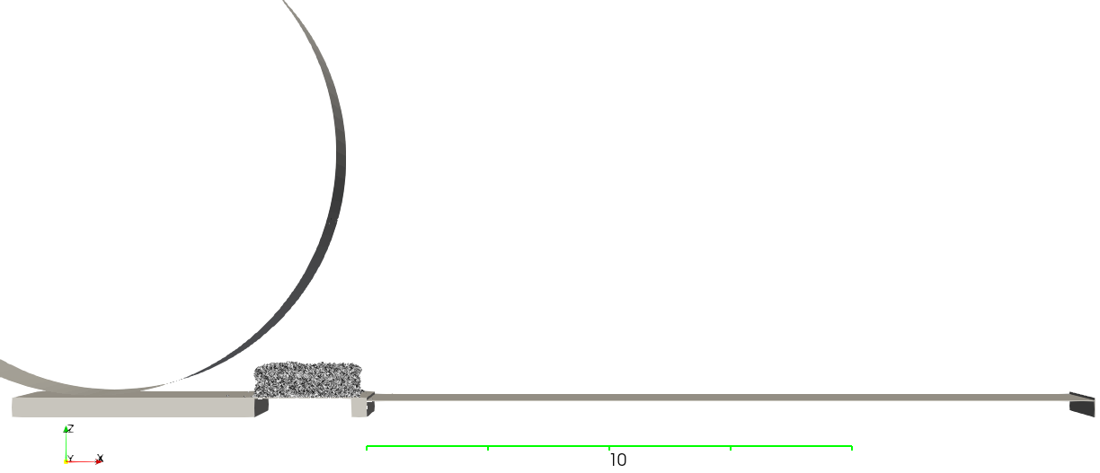
The following geometric setup is used for the simulation of powder spreading with a roller or a blade implement from a reservoir. The roller is modeled based on 125 linear segments of a circle with a diameter of 10 mm and the blade is characterized by a edge and a thickness of 2 mm. For roller simulations, 42,000 particles are used, whereas for the blade simulations, the number of 21,000 particles was used. For selected simulations that involve a larger roller with a diameter of 20 mm or a higher layer thickness, 105,000 particles are used. These numbers were chosen based on a sensitivity study and represent the threshold where a larger number did not significantly affect simulation results. The roller simulation require a larger number of particles due to the fact that the pile in front of and underneath the roller needs to be realistically scaled to the roller diameter. A larger roller thus requires more particles whereas a higher blade does not. The dimensions of the powder reservoir and powder bed are similar to what has been used in previous work [100, 67, 108, 109, 82, 83]: the dimension perpendicular to the spreading direction is 1 mm with periodic boundary conditions, the powder bed has a length of 12 mm and quality metrics are evaluated over a 5 mm length, starting 3 mm after the beginning of the powder bed to avoid potential edge effects in the beginning or the end. The thickness of the layer is 3.5 times the median particle diameter (i.e., 100 for a 15-45 powder or 35 for a 0-20 powder as described below). In the beginning of the simulation, particles are randomly allocated on a grid in the powder reservoir. The particles drop down due to the gravitational force and the powder reservoir piston moves the pile of powder up and in front of the spreading tool. This situation is depicted in Figure 1, just before the spreading tool starts to move across the powder bed.
2.3 Quality metric: Spatially resolved packing fraction
The primary metric analyzed in this work is the 2D packing fraction field of the powder bed and its mean and standard deviation for a given powder layer. The computation and motivation of this metric is described in detail in [67] and will only be covered briefly here. The spatial resolution of the field metric is 100 in the length and width direction (denoted as bins), which is approximately the diameter of a typical laser spot. This 2D-field allows to better understand the uniformity of the powder bed. For example, a low standard deviation of the packing fraction field indicates a high level of uniformity. The packing fraction is evaluated in two steps. First, each bin is further divided into smaller cubical 3D voxels with a side length of 2.5 for a numerical integration of the particle volume. The voxel size is chosen as to minimize the error coming from the volume of particles cut by the segment walls. Finally, the packing fraction of the powder layer is evaluated as the ratio of the volume occupied by particles to the volume of the powder bed confined by the actual mean layer height.
Remark: For the calculation of the packing fraction, the nominal layer height is commonly employed in the literature. We do not use the nominal layer height but the actual (calculated) mean layer height. This is important since the nominal layer height usually is considerably higher than the actual mean layer height of a spread layer. The mean layer height is calculated as the mean value of the layer heights of all 100 bins [67].
2.4 Powder model parameters
The particle size distribution (PSD) was fitted to experimental laser diffraction measurements in our previous work [109], and the same values for the -percentile (D10), median (D50) and -percentile (D90) are fitted to a lognormal distribution in this work (D10 = 20.2 , D50 = 27.0 , D90 = 36.0 ). Most other powder model parameters are also kept the same as referenced in [109, 82, 83], and are listed in Table 1.
This work will focus on evaluating powders with a high level of cohesion. Cohesive forces in the model are primarily determined by the surface energy of the particles. A higher value of defines a more cohesive powder. In [100], we showed that the critical dimensionless group that defines the cohesiveness of a powder is the ratio of gravitational and adhesive forces, which scales according to:
| (2) |
As shown in [100], the behavior of a given powder is similar as long as the ratio stays constant. For example, a powder with a lower density, such as an aluminum alloy, and a larger size distribution might behave similar to a higher density metal, such as steel, with a smaller size distribution. Making use of this self-similarity condition, one can model the behavior of a powder based on the known behavior of others. The present model was calibrated on the 15-45 Ti-6Al-4V powder (D10 = 20.2 , D50 = 27.0 , D90 = 36.0 ), with a surface energy value of = 0.08 [83, 82]. In this work, we aim to model a very fine powder that has the same surface energy as the previously calibrated 15-45 Ti-6Al-4V powder. An exemplary commercially available 0-20 Ti-6Al-4V powder with D10 = 7 , D50 = 10 and D90 = 13 matches this requirement and can be modeled by keeping the particle distribution of the 15-45 powder, while using a modified surface energy in the model that is calculated with the transformation rule
| (3) |
Using this transformation rule, the modified surface energy takes on a value of or 0.64 , i.e., the surface energy is increased by a factor of 8 as compared to its consistent physical value. The same surface energy used to describe particle-particle interactions is also applied to particle-boundary interactions.
| Parameter | Value | Unit |
|---|---|---|
| Density | 4430 | kg/m3 |
| Poisson’s ratio | 0.342 | - |
| Penalty parameter | 0.34 | N/m |
| Coefficient of friction | varied: 0.0-1.0 | - |
| Coefficient of rolling friction | 0.07 | - |
| Coefficient of restitution | 0.4 | - |
| Surface energy | varied: 0.02-2.56 | mJ/m2 |
| Hamaker constant | J | |
| Cut-off radius adhesion | - |
Furthermore, even though relatively cohesive metal powders have a significantly different flow behavior than coarse granular media such as dry sand, flow behavior of metal powders can be generalized more easily due to their relatively similar, high stiffness [111], indicating that results in this work can be generalized to cohesive metal powders more broadly.
3 Results
It has previously been shown that spreading cohesive powders, usually with properties such as small diameters (e.g., D50 below 20 ) or low density-materials (e.g., Al-alloys), with a high quality and repeatability is challenging. To address this challenge, both, well-established and novel spreading approaches are presented and studied in detail. Each approach will be presented with motivation, parameter setup, and results in the following.
3.1 Spreading of fine powders with roller vs. blade
To understand the experimentally and computationally observed challenges of spreading cohesive powders in more detail, a parameter study to examine the spreadability of increasingly cohesive powder via blade and roller implements was performed. The varied parameter is the surface energy , which is spaced logarithmically between for blade spreading and for roller spreading.
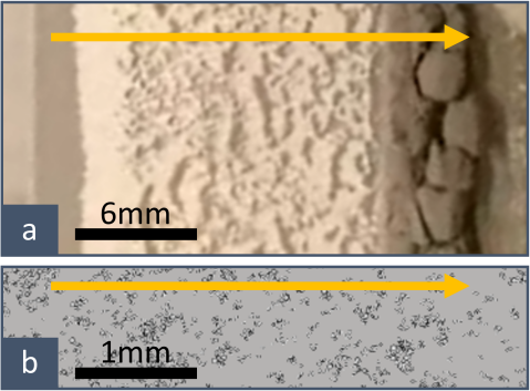
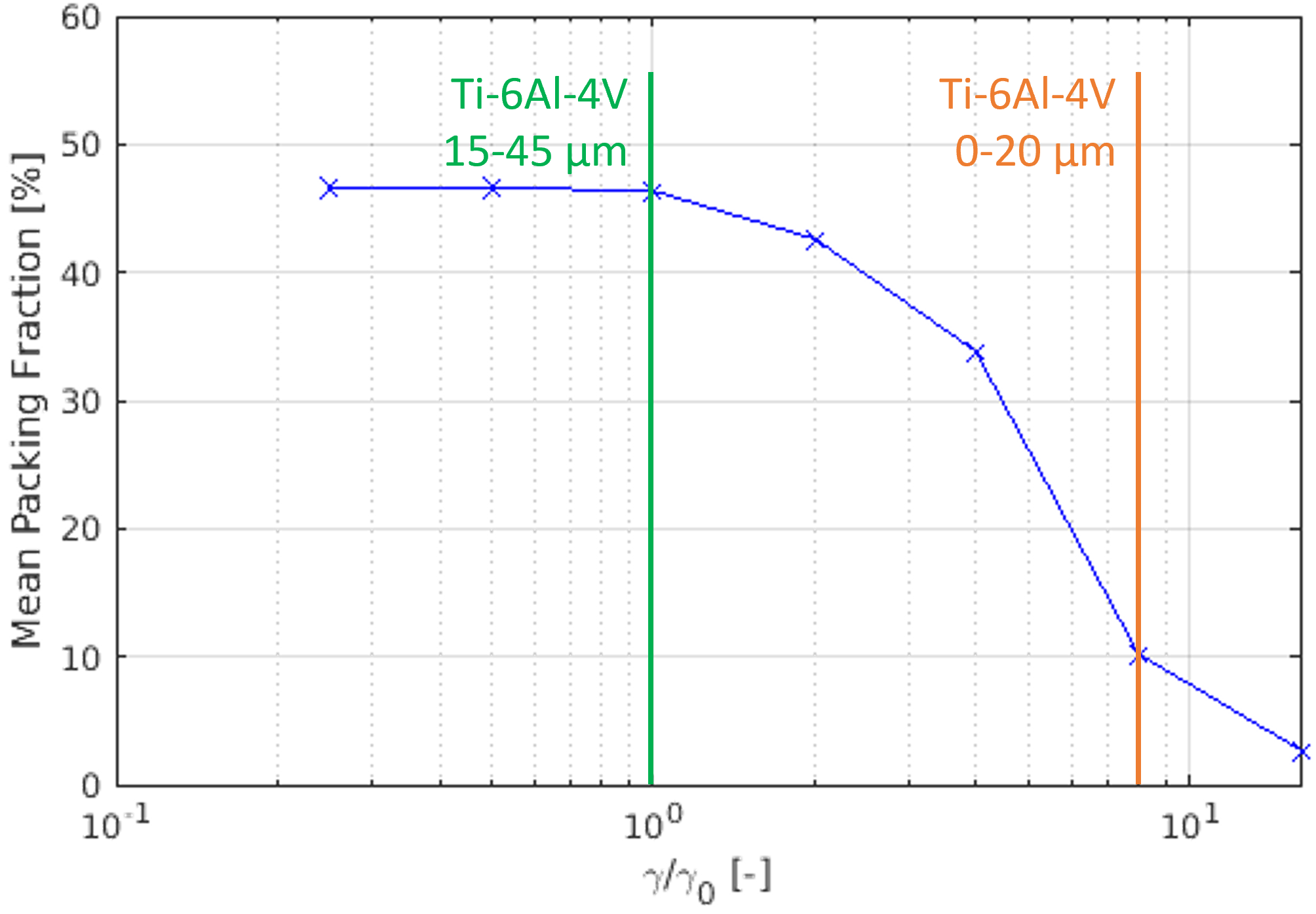
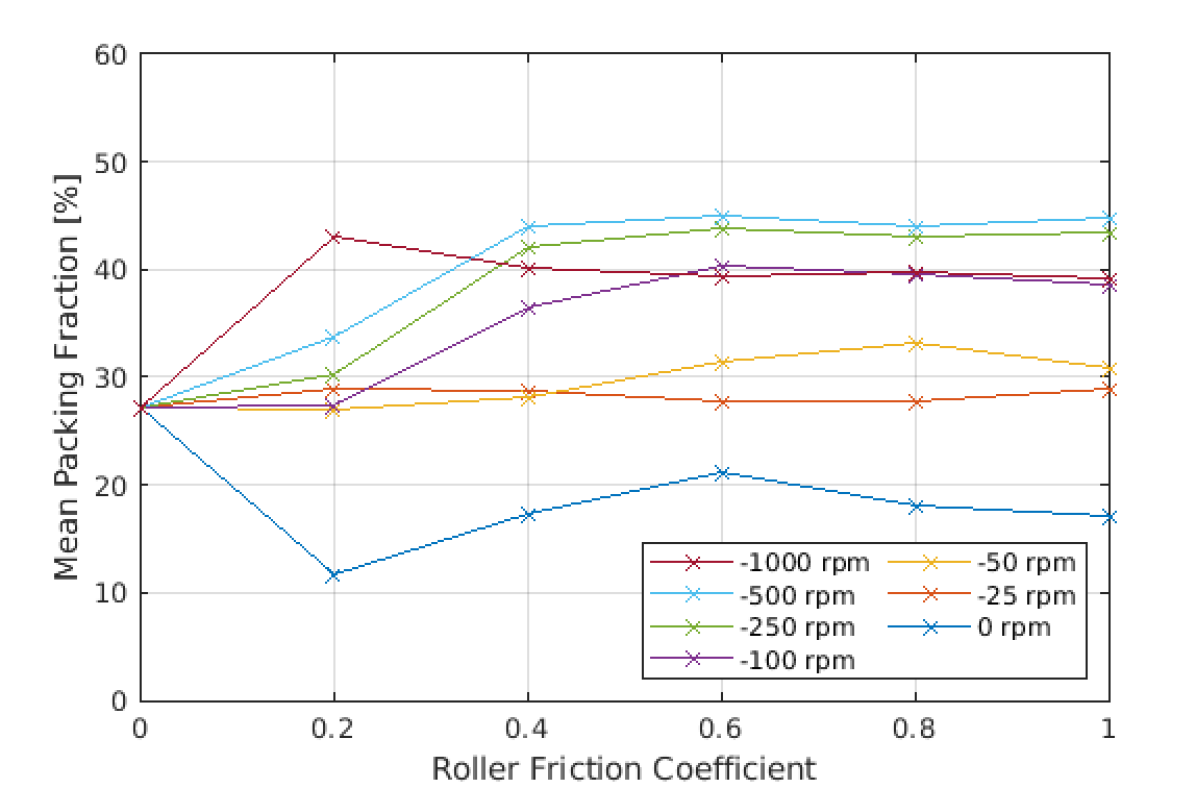
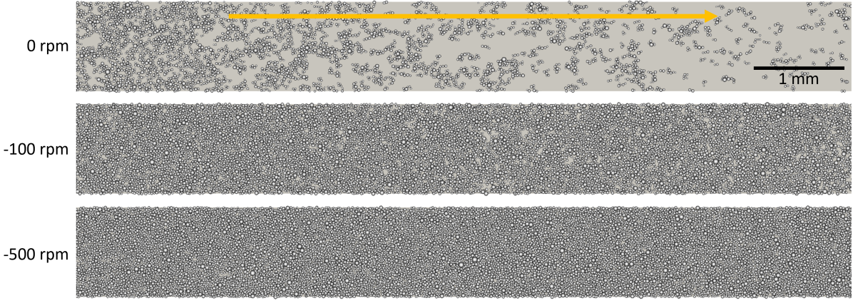
For blade spreading, the expected behavior of deteriorating powder layer quality, as measured by mean packing fraction, with increasing cohesiveness is observed in Figure 3(a). The study was executed with a spreading velocity of . For reference, markers are added, indicating which level of cohesiveness corresponds to which representative powder. The DEM parameter setting corresponding to the Ti-6Al-4V powder with a 15-45 size distribution has previously shown very good agreement with experimental studies [109, 82, 83] and the surface energy parameter has been translated to the 0-20 size distribution as described in Section 2.4. There is a rapid deterioration of spreadability with a surface energy above , with the Ti-6Al-4V 0-20 powder being almost unspreadable. Note, that a mean packing fraction value in the range of means that there are large void regions on the substrate after spreading. This is in close agreement with experimental and simulation-based results in [82]. Qualitative powder spreading results for the 0-20 size distribution in a well of 100 depth is depicted in Figure 2. Clearly, the experimental as well as the computational layers are both very sparse, only being covered occasionally by clusters of the very cohesive powder.
When using a roller implement without rotation instead of the 90∘ blade, the general trends stay the same regarding spreadability – high packing fraction for non-cohesive powders, a rapid drop in packing fraction above , and basically no powder being spread beyond (see Figure 3(b)). The behavior significantly changes when the roller counter-rotates with 500 rpm. While the packing fraction initially decreases with increasing surface energy, it starts to increase again above and reaches a local maximum for a surface energy level above , before getting too cohesive and unspreadable again.
This result is surprising, as even the highly cohesive powder corresponding to Ti-6Al-4V 0-20 , which was unspreadable in experiments using a standard blade or non-rotating roller implement [82, 83], shows good spreadability with the rotating roller. It also implies that under the appropriate spreading conditions, even highly cohesive powders can successfully be applied on a substrate, indicating a powder-specific spreading window. Thus, the following sections will focus on the fine and highly cohesive Ti-6Al-4V 0-20 powder corresponding to a dimensionless cohesiveness of 8.
3.2 Powder-specific parameters for roller spreading
When spreading powder with a roller, AM practitioners usually have influence over several key spreading parameters without having to make modifications to the machine. These are traverse (spreading) velocity , rotational velocity and surface properties of the roller implement, in this work limited to the roller friction coefficient . Modifying other parameters such as roller diameter or deposition via reservoir vs. hopper is usually described by the machine capabilities and requires more substantial modifications.
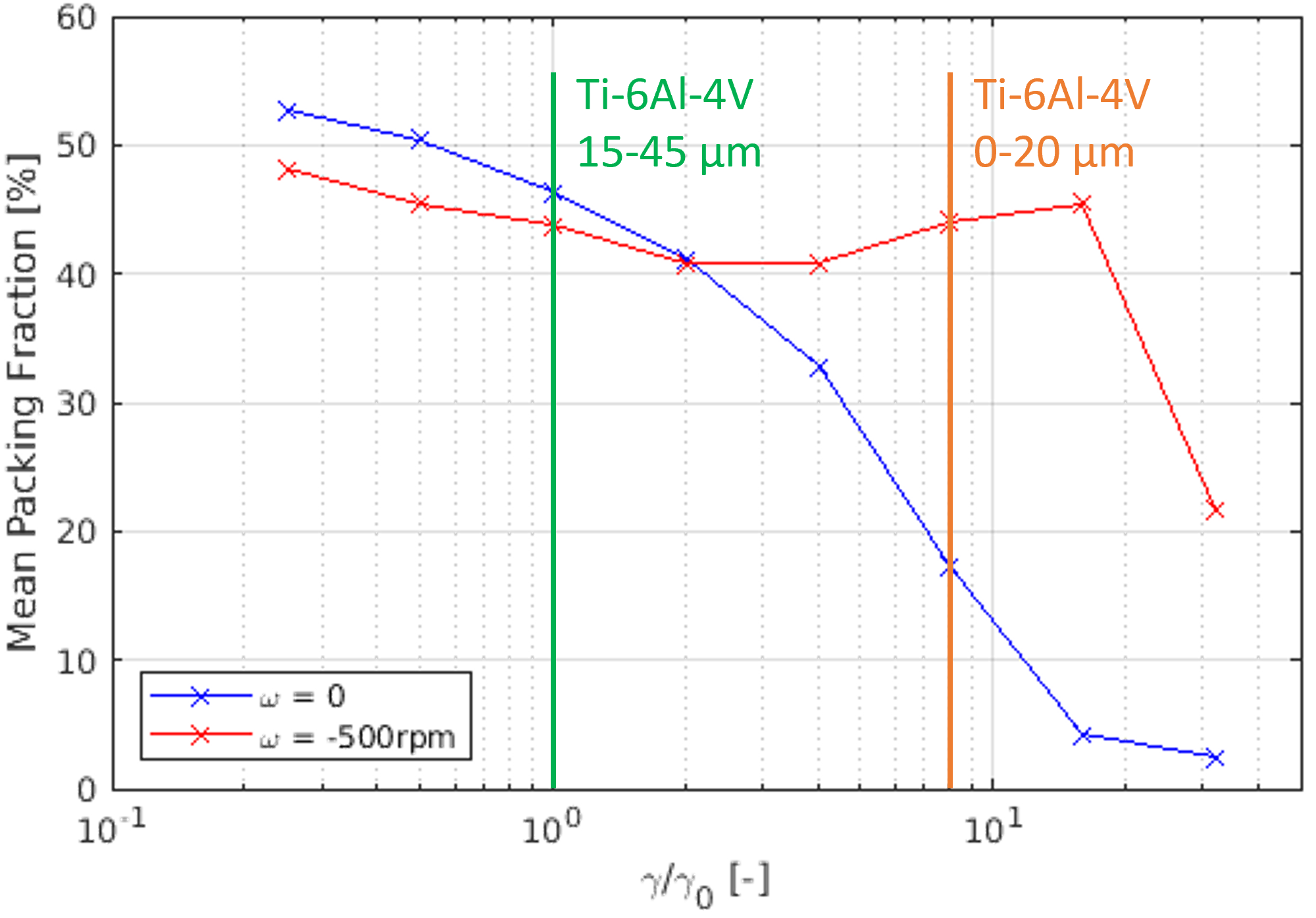
To better understand the impact of these three key parameters that can be easily influenced by a practitioner, a parameter study has been performed. Figure 4 shows the results for spreading velocities in individual plots. Within each plot, the mean packing fraction of a spread layer is shown for simulation results with and rpm. Negative values for the rotational velocity depict a counter-rotating direction of the roller.
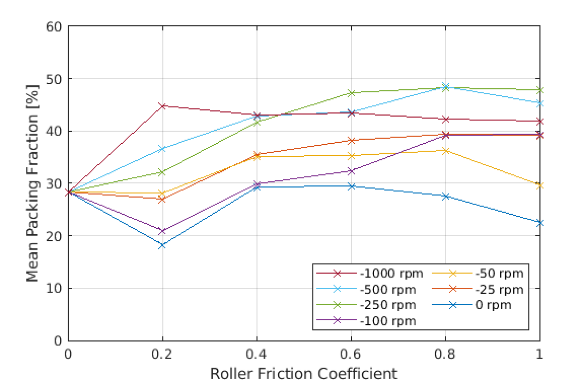

There are several general trends observable in the data. First, with increasing traverse velocity the packing fraction first lightly increases (from to ), before it decreases again for higher velocities. This behavior of an optimal spreading velocity is in agreement with experimental results. Nan and Gu [112] argue that for very small spreading velocities (e.g., ), the shearing strain rate is too small to sufficiently counteract the interparticle cohesion to spread a dense layer. On the other hand, for very large traverse velocities, the inertia of particles can be a limiting factor. With increasing powder deposition rate, the supply flow within the powder pile towards the gap might limit how much powder can be deposited by the tool. However, spreading velocity is the only parameter that directly relates to spreading time, and thus printing throughput. This means that a trade-off between throughput and quality has to be made, with the reduction in quality setting in around for the analyzed powder. For example, the highest packing fraction achieved for is 48.6%, compared to 48.1% for and 45.0% for .
The friction coefficient initially has a significant impact on the layer packing fraction, but beyond a friction coefficient of , the impact is negligible. is common for normally machined steel roller surfaces [113].
Rotational velocity is the most critical parameter, generally making the difference between not forming a continuous powder layer and spreading a relatively dense and homogeneous layer with packing fractions up to 50% (see Figure 5). Critically, there is a plateauing effect visible as the rotational velocity increases. Between rpm and rpm, only a small increase in packing fraction was observed and for the very high velocity of rpm the layer quality generally decrease again. Interestingly, for the higher angular velocity, even a small coefficient of friction is sufficient to achieve high packing fractions. The high velocity paired with the low friction coefficient leads to a sufficient amount of shear in the powder pile to deposit the particles. However, with higher friction coefficients, the roller is creating dust and ejecting particles from the powder bed, leading to lower resulting packing fractions.
These results indicate, that there exists a best-possible, powder-specific parameter set, for which even highly cohesive powder can be deposited successfully and with a high density and uniformity.
Interpreting the results, we want to draw an analogy between powder spreading with a roller and the conventional manufacturing techniques grinding or milling. During high speed grinding for example, the contact zone where the tool interacts with the work piece is characterized by a viscous shear layer [114]. This layer is comparable to the resulting shear zone when spreading a cohesive powder pile with a counter-rotating roller. For a given traverse velocity, a higher cutting velocity / rotational velocity in peripheral milling and grinding processes is known to reduce the amount of material removed per rotation, leading to decreased cutting forces and an increase in surface quality [115, 116], effects that are also observed for the spreading of very cohesive powders using a counter-rotating roller.
3.3 Spreading via angular oscillation
Experimental results have shown that the powder layer quality, when spreading with a rotating roller, is constrained by the manufacturing accuracy of the tool [83]. Since powder layers in practice usually are in the range of 30-100 thickness, a roller manufacturing runout of only 10 has a significant impact on the layer topology, usually creating a wave-like powder layer profile of varying thicknesses. To circumvent this requirement of high manufacturing precision, the concept of angular oscillations for powder spreading with a roller or curved blade is proposed. By using only a segment of the roller surface, the effect of manufacturing runout is mitigated.
Specifically, instead of a constant rotational velocity , an oscillating rotational velocity that depends on the amplitude , the frequency and the time is defined as:
| (4) |
This definition of the angular velocity implies an angular displacement of a specific point on the roller surface with the maximum amplitude which is defined as:
| (5) |
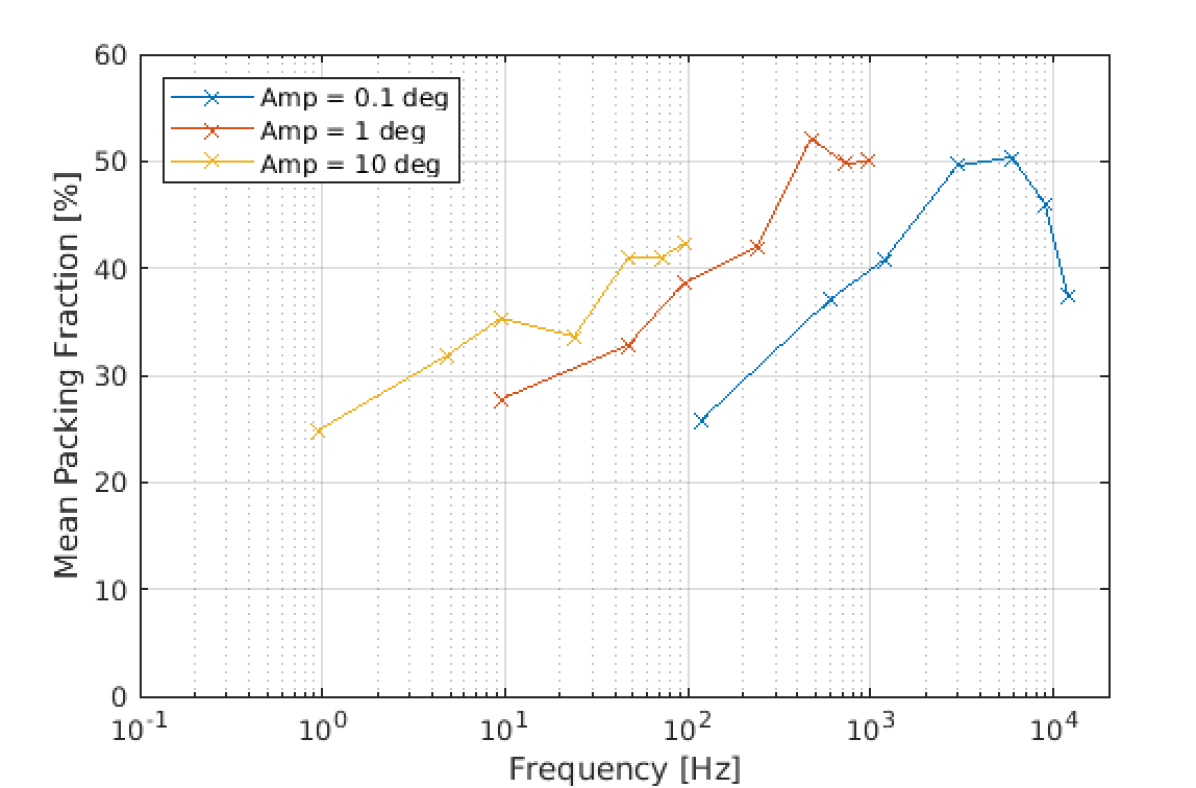
This angular oscillation can be interpreted in two ways. First, the frequency of the oscillation can help to understand the regime, e.g., above 20 kHz is commonly defined as ultrasonic vibration. Alternatively, the maximum (absolute) circumferential velocity can be related back to an equivalent rotational velocity if the oscillation’s maximum speed is taken as the velocity of a constant rotation. That equivalent constant rotational velocity can be easily understood in context of e.g., the results in Section 3.2. For reasons of better interpretation, the amplitude and equivalent rotational velocity are being kept as independent variables and the frequency is chosen as dependent variable. The smallest amplitude is chosen to be approx. half of the median radius of the PSD (with ), which corresponds to 0.08∘ or 7 of amplitude on the roller surface. By increasing in orders of magnitude, the other examined values are 1∘ (i.e., 87 amplitude on the roller surface, corresponding to the cutoff diameter of the PSD) and 10∘ (i.e., 873 amplitude on the roller surface). For the equivalent rotational velocity, values ranging from 10 rpm to 1000 rpm are chosen, which cover approximately the same range as in Section 3.2, while the traverse velocity is constant for all simulations at , which was identified as best compromise between spreading accuracy and throughput in Section 3.2. The full set of parameters is given in Table 2.
| Equivalent max rotational velocity in [rpm] | Frequency for 0.08∘ in [Hz] | Frequency for 1∘ in [Hz] | Frequency for 10∘ in [Hz] |
|---|---|---|---|
| 10 | 119 | 9.55 | 0.955 |
| 50 | 595 | 47.7 | 4.77 |
| 100 | 1190 | 95.5 | 9.55 |
| 250 | 2975 | 239 | 23.9 |
| 500 | 5950 | 477 | 47.7 |
| 750 | 8925 | 716 | 71.6 |
| 1000 | 11900 | 955 | 95.5 |
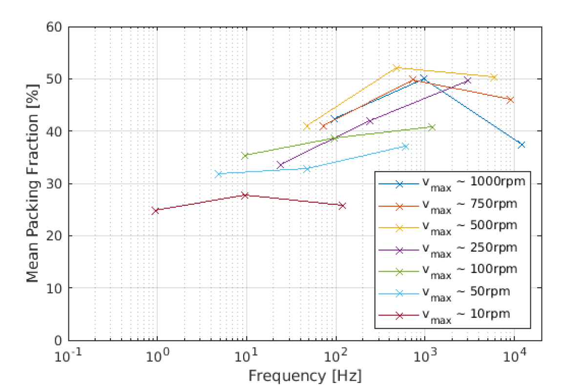
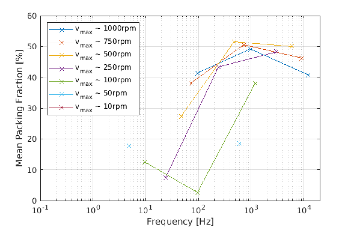
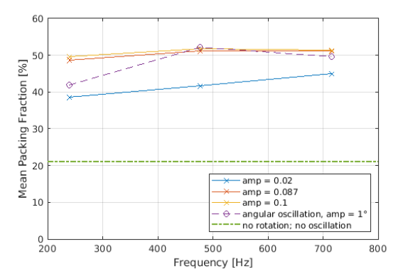
Figure 6 shows the results of the parameter study broken down from two different perspectives. The data points in Figure 6(a) and Figure 6(b) are the same, but they are plotted on a different legend to allow for deeper understanding of the results. Looking at Figure 6(a), it is evident that for each amplitude, an increase in frequency is generally increasing the packing fraction. Similarly to the pure rotational spreading in Section 3.2, the plateau is followed by a decline for very high frequencies. Furthermore, the highest packing fractions are achieved with a medium amplitude around 1∘. This is visible both in Figure 6(a) as well as by the ’hat’ shape of the curves in Figure 6(b) where the middle data point of each curve represents the 1∘-amplitude data point. From Figure 6(a) it can be concluded that employing a smaller amplitude requires a higher frequency to reach similar results. Shifting the perspective to Figure 6(b) helps understand this behavior better as each amplitude-frequency combination is mapped to an equivalent maximal rotational velocity. With increasing equivalent maximal rotational velocity, the packing fraction increases, up to 500 rpm. Beyond the peak at 500 rpm, the packing fraction decreases again, similarly to the pure rotational simulations. Overall, best results are achieved for values between 0.5-5 kHz and amplitudes of 1∘ or below, which corresponds to equivalent maximal rotational velocities around 500 rpm with the employed roller geometry.
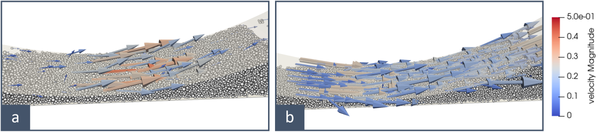
Qualitative analysis of the particle movement revealed that for very high frequencies and small amplitudes, corresponding to an equivalent velocity above 500 rpm, the inertia of the powder is too high for the roller oscillations to affect the particles. Figure 7 shows the exemplary comparison of the highest frequency oscillation (1000 rpm equivalent, 0.08 0.1∘ amplitude) and the best layer (500 rpm equivalent, 1∘ amplitude). The arrows indicate the velocity of each particle, with the color being on the same scale as shown in the legend. The length of the arrows for the 1000 rpm case is scaled by a factor of 0.5 compared to the arrows of the 500 rpm case in order to account for the difference in reference velocity of the roller (1000 rpm vs. 500 rpm). In the high frequency case, only particles that are vertically underneath the centerpoint of the roller are affected by the angular movement. This is a typical behavior for a non-rotating/non-oscillating roller where particles in the narrowest part of the gap experience high forces and particles outside that region are largely unaffected. For the best case in Figure 7b, most particles the roller is in contact with are evenly impacted (many similarly sized/colored arrows). This even velocity field indicates strong engagement of the roller with the powder pile. The oscillating nature then allows for a breaking of cohesive bonds between particles and creates a relatively uniform surface.
Comparing the oscillating spreading to the pure rotational spreading, several additional differences are visible. For rotational spreading, the roller surface is completely covered with powder as it adheres to the roller. This is an effect that is also visible in experimental studies performed in our lab. For oscillating spreading, only a small part of the roller surface interacts with the powder and thus has particles adhering to it. Potentially related to that, rotational spreading shows significant ejection of particles from the spreading zone forward onto the powder bed. This creates a kind of dust of particles that are being ejected continuously as the roller moves, especially for high angular velocities. With the oscillating spreading, almost no such dust creation was visible.
3.4 Impact of reduced substrate adhesion
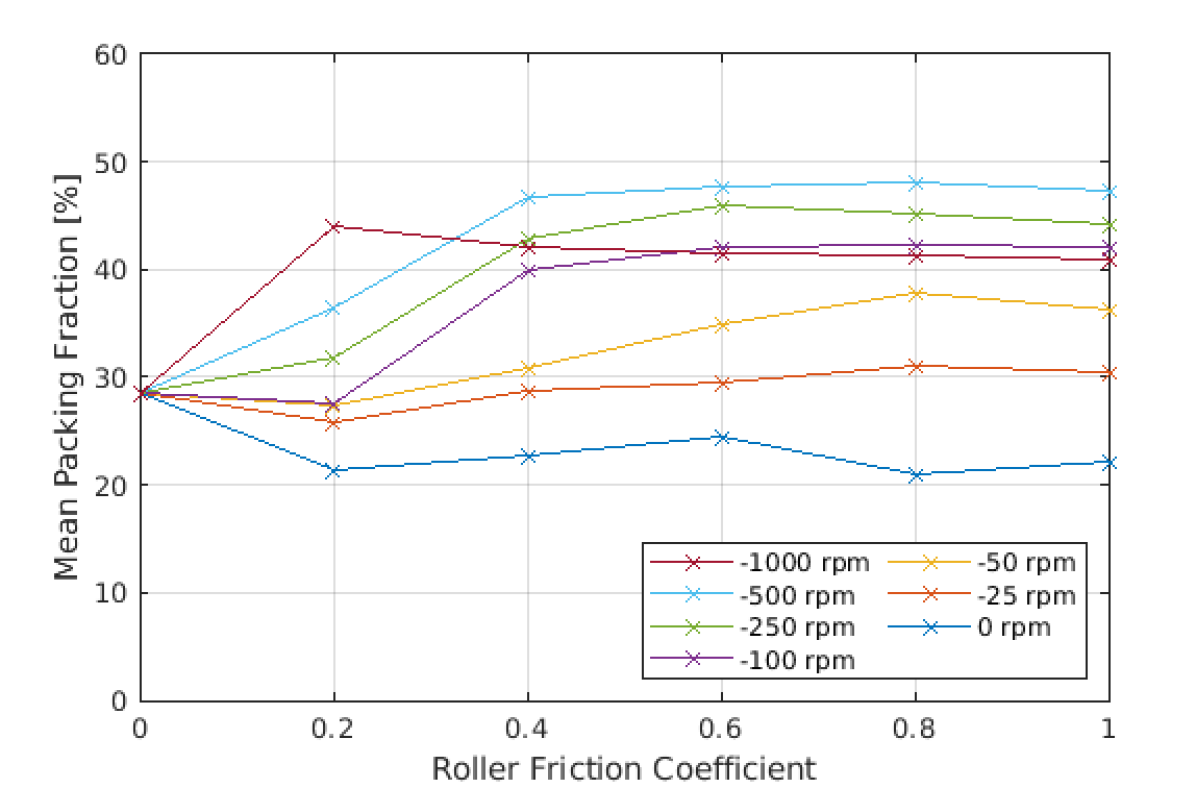
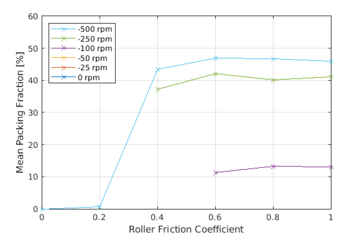
When spreading powder during a LPBF build, it is spread over the previous layer. This means that the substrate is a combination of previously spread powder and melt tracks. The surface properties of powder and melt tracks are quite different and powder particles might adhere differently well. To evaluate the impact of a change in surface properties of the underlying surface (i.e. substrate, powder bed or melt track), the substrate surface energy, as critical parameter for the spreadability, is reduced, which makes the spreading more challenging and allows to assess the robustness of the different spreading strategies. In this section the substrate surface energy levels are reduced by a factor of 10, meaning that: . For this changed setting, the parameter studies from Section 3.2 (for traverse velocity of v = ) and Section 3.3 (also v = ) are repeated.
Figure 8(a) shows the results of the equivalent study from Section 3.2. The main insight is that for the roller rotation of = -500 rpm and a roller friction coefficient of 0.4 or larger, the mean packing fraction is comparable to the case with the normal surface adhesion levels of the substrate. E.g., for the case of = -500 rpm and = 0.6, the packing fraction is almost identical (47.0% for vs 47.7% for the default substrate surface adhesion). The impact of roller rotation seems to be significantly more important for a lower substrate adhesion value. For = -250 rpm, the achievable mean packing fraction is comparable to the = -100 rpm case in Section 3.2, however powder is not being spread below = 0.4. For rotational velocities below = -250 rpm, the layer packing fraction is either very low (around 10-15% for = -100 rpm and 0.6) or no powder is spread at all (all cases below = -100 rpm). In this case, the powder pile is simply being pushed across the substrate without being deposited and no data point is displayed in Figure 8(a).
For the spreading with angular oscillation, the results are similar. For low comparable equivalent maximal rotational velocities, no powder is deposited (e.g., 10 rpm and one 50 rpm scenario which are therefore not plotted). The best spreading results on the other hand are comparable to the best spreading conditions in the unaltered simulations in Section 3.3. For example, the best result is achieved with = 500 rpm, amplitude A = 1∘, and frequency f = 4.77e-1 kHz, where the default case had a mean packing fraction of 52.2% and the scenario with the reduced substrate adhesion achieves 51.5%.
In summary, while spreading becomes more challenging and in several cases infeasible, the spreading conditions that produce best results on a substrate that has similar cohesive properties as the powder also produce best results on a less cohesive substrate. Even as substrate conditions change significantly, the layer packing fraction stays very consistent which underlines the robustness of these spreading strategies and parameter choices.
3.5 Spreading with a roller without adhesion
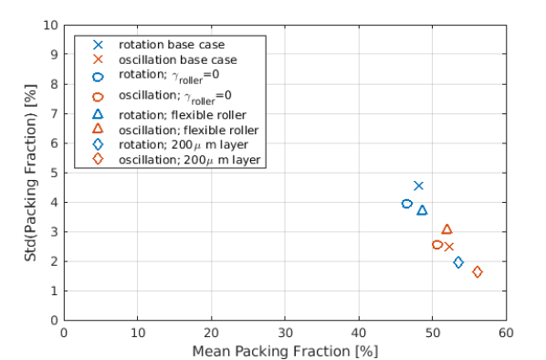
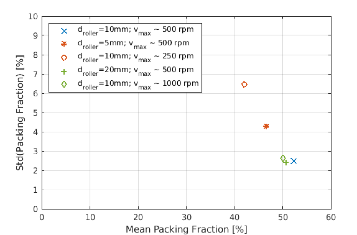
Besides influencing the surface roughness by changing the surface profile of the spreading implement – in this work a roller – practitioners could also change the material to affect the adhesion of particles to the tool. For blades, we have previously shown that a low level of adhesion of particles to the tool is beneficial for spreading [67]. Here, we look at the limiting case of , meaning that particles do not adhere to the roller at all. While this case is unrealistic in reality, it is the limiting case showing what theoretical maximum improvement could be reached due to the choice of material. Figure 9 includes the results of two exemplary simulations where the adhesion for the roller is set to zero. The mean packing fraction is on the abscissa, with the ordinate showing the standard deviation of the packing fraction field. First, the best case of the pure counter-rotating simulation with v = from Section 3.2, i.e., = 500 rpm and = 0.8 (blue cross), is rerun without adhesion to the roller (red cross). Second, the best case of the angular oscillation simulation with v = from Section 3.3, i.e., = 500 rpm, amplitude A = 1∘ and = 0.8 (blue circle), is rerun without adhesion to the roller (red circle).
Both simulations show no significant impact of the roller adhesion on the powder bed. In the simple counter-rotating case, the reduced adhesion even slightly reduces the mean packing fraction from 48.1% to 46.5% while increasing uniformity in terms of a slightly lower standard deviation which decreases from 4.6% to 3.9%. For the oscillation simulations, the mean packing fraction also slightly decreases from 52.2% to 50.7% while the standard deviation of the packing fraction field stays almost the same with a minimal increase from 2.5% to 2.6%.
Summarizing these results, reducing the surface adhesion of the roller has no significant impact on the quality of the powder layer when using optimal parameters.
3.6 Spreading with a flexible roller
Flexible blades have shown to be advantageous to mitigate singular effects such as streaking [82] and to prevent tool damage in case of collisions, but also might help with avoiding peaks in the force the spreading implement exerts on the powder bed. These properties are likely to be transferable to rollers made from or covered with soft material as well. For example, Tang et al. [117], employ a flexible roller in an experimental study. The tool has a stainless steel core with a diameter of 5 mm and is being coated with fluorine rubber (E-modulus = 7.84 MPa) with a thickness of 1.5 mm (outer diameter of 8 mm) to achieve condensed layers of a powder with weak flowability.
With an integrated DEM-FEM framework developed in our previous contributions [118, 119], we simulate powder spreading employing a flexible, rubber-coated roller with a rigid core (see Figure 10). Keeping the outer diameter of the roller at 10 mm, the roller has a rigid core of 8 mm diameter and is covered by a 1 mm layer of compliant material (a comparable geometry was used by Tang et al. [117]). The inner rigid core is modeled via Dirichlet boundary conditions as employed throughout the previous chapters. The outer (rubber) layer is modeled as a hyperelastic Saint Venant Kirchhoff material with an elastic modulus of 5.53 MPa and discretized with approx. 700 finite elements (FEM). In radial direction, the elastic layer is represented by three finite element layers. This material property emulates a nitrile (Buna-N) O-ring stock (McMaster-Carr, 9700K16), that was previously used in [82] for a flexible blade.

In analogy to the simulations in Section 3.5, exemplary spreading scenarios using the counter-rotational as well as the angular oscillation approach, both for v = (see Section 3.2), are analyzed. For the counter-rotating scenario, the layer quality increases slightly when using the flexible roller, indicated by the similar packing fraction (48.6% vs. 48.1%) but slightly decreased standard deviation of the packing fraction field (3.7% vs. 4.6%), compared to the base scenario from Section 3.2 (yellow cross vs. blue cross). Also for the angular oscillation approach, the influence is rather small. While the mean packing fraction is comparable as well (51.9% vs. 52.2%), the standard deviation of the packing fraction field increases slightly (3.0% vs. 2.5%) compared to the base scenario from Section 3.3 (yellow circle vs. blue circle).
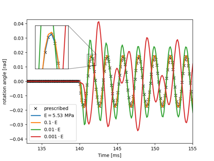
To study the shear deformation of the rubber coating due to the rotation, Figure 11 shows the rotation angle (see Eq. (5)) of one point on the outer surface with respect to the initial configuration over time for the oscillating roller. Using the Young’s modulus ( MPa) of nitrile (Buna-N) O-ring stock (blue curve in Fig. 11), the rubber coating follows the prescribed rotation almost exactly. Even a reduction of the Young’s modulus by a factor of 10 (orange curve) shows only a negligible difference to the prescribed rotation. Only at a reduced Young’s modulus by a factor of 100 the outer surface overshoots the prescribed rotation and at a reduction of 1000 the rubber coating is so soft that it cannot follow the prescribed rotation. Thus, a rubber coated roller is expected to combine both the stiffness to appropriately follow the applied kinematics while being compliant enough to have the benefits of spreading with compliant blades.
While the compliant roller did not result in a visible improvement of the powder layer quality, the important conclusion of this section is that it also did not lead to a quality decrease. This is important since compliant tools have significant practical advantages, e.g., in preventing tool damage in case of collisions or in mitigating singular effects such as streaking of very large particles or agglomerates [82], which have not been considered in the present powder spreading simulations.
3.7 Impact of layer thickness
Similar to above (see Section 3.5), exemplary spreading scenarios using the counter-rotational as well as the angular oscillation approach are analyzed for an increased layer thickness of 200 . This layer thickness roughly corresponds to . If successfully fused, a thicker layer is an effective means to increase throughput when building up a part – when resolution requirements permit the thicker layers.
As expected, the increased layer thickness significantly increases layer quality for both spreading approaches. Figure 9 shows the results of the two exemplary simulations in purple. Similar to Section 3.5, the cross markers indicate the pure counter-rotating approach (v = , = 500 rpm and = 0.8) while the circle markers represent the angular oscillation simulations (v = , = 500 rpm, amplitude A = 1∘ and = 0.8).
For the rotational case, the mean packing fraction increases from 48.1% to 53.5%, while the standard deviation decreases significantly from 4.6% to 2.0%. For the angular oscillation scenario, the mean packing fraction even increases from 52.2% to 56.1%. The standard deviation decreases even further from 2.5% to 1.6%.
This significant improvement in layer quality confirms previous studies [75, 76, 67, 77, 57]. It has to be noted that there are two factors contributing to this increased packing fraction. First, in a thicker layer, powder flow through the spreading gap is improved and the impact of singular effects such as locking or streaking of very large particles or agglomerates is decreased. Second, the impact of the flat bottom boundary, which prohibits optimal particle arrangements at the boundary, on the average packing fraction across the layer thickness is decreased.
The higher packing fraction and increased uniformity is beneficial for subsequent melting or binder absorption, rendering thick layers of cohesive powders a potentially promising avenue to increasing throughput in metal AM.
3.8 Impact of roller diameter
For a practitioner using a roller spreading implement, the roller diameter is another important parameter that can be optimized. To investigate this aspect, we look at the impact of changing the roller diameter, specifically comparing the diameters 5 mm, 10 mm and 20 mm. Again, in a similar fashion as in the previous studies, a base case for the rotational (v = , = -500 rpm and = 0.8) and the angular oscillation (v = , = 500 rpm, amplitude A = 1∘ and = 0.8) spreading is compared to corresponding simulations with increased roller diameter. For the 20 mm roller simulations, due to the larger size of the roller, the number of particles is increased to 105,000. This allows for a heap of powder in front of the roller that resembles actual spreading more realistically. Given the otherwise unchanged simulation parameters, the surface velocity of the larger roller is significantly higher (and for the smaller roller significantly smaller) compared to the d=10 mm roller for = -500 rpm. The velocity component originating from the angular motion doubles/halves given the same angular velocity. E.g., for the 20 mm roller the angular motion of -500 rpm could be compared to an angular velocity of -1000 rpm of the roller with a diameter of 10 mm; vice versa for the 5 mm roller with -250 rpm.
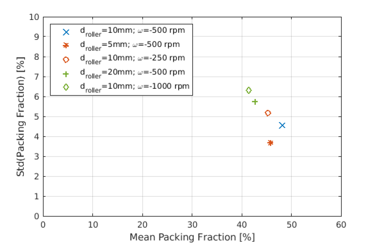
For both the rotational simulations (see Figure 12(a)) as well as the angular oscillation approach (see Figure 12(b)), the base scenario of d=10 mm and -500rpm achieves the highest packing fraction.
The powder layer density decreases with the larger roller as well as the smaller roller, compared to the = -500 rpm scenario (see Table3). E.g., for the pure rotational simulation, the increased roller diameter leads to a decrease of the packing fraction from 48.1% to 42.7%, while the standard deviation increases from 4.6% to 5.8%. For the angular oscillation, the packing fraction slightly decreases from 52.2% to 50.6% while the standard deviation remains almost unchanged at 2.4% (vs. 2.5% in the base case).
However, when comparing the different roller diameter simulations with an equivalent circumferential velocity instead of the similar angular velocity, the picture slightly changes. Generally, the simulations with similar circumferential velocity result in very similar powder layers. E.g., comparing the simulation with d=20 mm and 500 rpm and the simulation with d=10 mm and 1000 rpm for the angular oscillation, the packing fraction and standard deviation are almost identical (mean of 50.6% for d=20 mm vs. 50.1% for d=10 mm and standard deviation of 2.4& vs. 2.6% respectively, see Table3.
| Rotation | Oscillation | |||
|---|---|---|---|---|
| d=10 mm, = -500 rpm | 48.1% | 4.6% | 52.2% | 2.5% |
| d=5 mm, = -500 rpm | 45.8% | 3.7% | 46.6% | 4.3% |
| d=10 mm, = -250 rpm | 45.2% | 5.2% | 42.0% | 6.5% |
| d=20 mm, = -500 rpm | 42.7% | 5.8% | 50.6% | 2.4% |
| d=10 mm, = -1000 rpm | 41.4% | 6.3% | 50.1% | 2.6% |
Given that the powder layer quality is comparable for the similar circumferential velocity, we can conclude that the changed geometry has relatively little impact compared to the kinematic spreading parameters.
3.9 Spreading via transverse oscillation
As alternative to the angular oscillation of the roller presented in Section 3.3, an oscillation can also be applied to the roller normal to the spreading direction. Therefore, the same roller parameters as in the previous studies are used, i.e., roller diameter mm, traverse velocity v = , coefficient of friction for the roller , and the same cohesive surface energy for roller surface, substrate and particles. Note that this transverse oscillation approach is not limited to rollers. Instead, the roller could e.g. also be replaced by a blade with circular edge. For the oscillation, the displacement in transverse direction is calculated via with the amplitude and frequency . In the following, the specific frequencies Hz and amplitudes mm are studied. Here, the amplitude mm corresponds to the same displacement as the amplitude for the angular oscillation based on the same roller diameter. So, the maximal velocity resulting from the oscillation is the same for these two cases.
Figure 13 shows the mean packing fraction for the chosen frequencies at different amplitudes. For the low amplitude the mean packing fraction is significantly lower than for the higher amplitudes under consideration. Though, the lowest mean packing fraction of achieved in this case is still significantly higher than the corresponding to the roller without rotation (see Figure 4(c)). At high amplitudes the influence of the frequency is minor, resulting in packing fractions in the range of . The highest mean packing fraction of is achieved for an amplitude mm and frequency Hz and is comparable to the packing fractions resulting from the roller with angular oscillation. Hence, the application of transverse oscillations represents a good alternative to achieve high packing fractions that is applicable to more general spreading tool geometries beyond simple cylindrical shapes.
4 Conclusion
This work investigates the spreading of very cohesive powder in PBF using a roller implement through computational simulations. Compared to spreading with a blade, using a counter-rotating roller allows to create thin powder layers of high quality with fine, cohesive powders when optimizing the kinematic parameters. This indicates that there is a material-specific process window for the deposition of these cohesive powders. For the investigated representative 0-20 Ti-6Al-4V powder, high counter-rotating angular velocities of 500 rpm, a friction coefficient of the roller of over 0.4 and moderate traverse velocities of around 10-25 achieved best results. The high level of shear and the moderate deposition rate allow for a uniform and dense layer. As experimentally shown by Penny et al. [83], a high manufacturing precision for the spreading apparatus is required in order to avoid a wave-like surface profile coming from the runout of the rotating roller. To mitigate the difficulty of manufacturing with such high precision, oscillation spreading patterns in angular direction and perpendicular to the spreading direction are proposed. Employing a frequency of approx. 500 Hz and an amplitude of 1∘ (corresponding to a value just larger than the largest particle diameter) showed best results, with a powder bed density that was higher than what was achieved with an angular rotation (52.2% vs. 48.1%). Furthermore, using very high frequencies (10 kHz or larger) in combination with very small amplitudes (i.e., 0.1∘) was shown to be less effective. When analyzing the impact of different properties of the underlying layer by means of a reduced level of adhesion of the substrate, it was shown that the spreading conditions that produce best results on a substrate that has similar cohesive properties as the powder also produce best results on a less cohesive substrate. For example, when reducing the substrate adhesion by a factor of 10, the powder bed density stays consistent when using the best parameter set for a default surface adhesion. On the other hand, one could also imagine using different materials for the roller. For the limiting case of no adhesion of the powder to the roller, no significant impact was seen on the powder layer quality, when employing the best spreading parameter set as derived for a roller with a normal level of adhesion. As another option to improve the spreading tool, flexible blades are known to mitigate singular defects such as streaking. While these singular effects are commonly not observed in computational work, we assume that it can be generalized from computational results. The examination of a rubber-coated roller showed no negative impact on powder layer quality. This is a positive result, as it shows that even the dynamic spreading patterns of angular oscillation are stable using compliant tools, while offering the benefit of mitigating singular effects such as streaking. Changing the geometry of the spreading tool to a larger roller decreased the powder layer quality, indicating that the optimal parameters for one geometry don’t necessarily translate directly to a similar spreading geometry of different scale. Lastly, we analyzed oscillating the roller not in angular direction, but perpendicular to the spreading direction. This approach yielded comparable results to the angular oscillation and offers a viable alternative to the other proposed spreading approaches in this work.
In conclusion, the proposed angular or traverse oscillation patterns with a compliant spreading tool and a high ratio of oscillation to traverse velocity are a very promising avenue with the following key benefits:
-
1.
high and uniform packing density in the range between 50 and 60 percent
-
2.
robust w.r.t. varying substrate conditions (e.g., reduced substrate adhesion)
-
3.
no runout problems as compared to pure rotation kinematics
-
4.
oscillation can even be extended to non-roller geometries
-
5.
compliant coating mitigates problems due to collisions or streaks
-
6.
powder layer quality further improves with increasing nominal layer thickness
For future work we see primarily two directions. First, the computationally examined concepts in this work need to be experimentally verified in order to be used by practitioners. Second, the less common hopper-based powder deposition approach should be analyzed in depth as well. Since it usually requires a smoothing pass with a tool, it might also benefit from the concepts described in this work.
5 Acknowledgements
Financial support at MIT was provided by the MathWorks MIT Mechanical Engineering Fellowship (to R.W.) as well as by the National Science Foundation, NSF Award 1720701. P.P., C.M., and W.W. wish to acknowledge funding of this work by the Deutsche Forschungsgemeinschaft (DFG, German Research Foundation) within project 414180263. We also thank Ryan W. Penny (MIT) for providing valuable insights from his experimental work with fine metal powders.
References
- [1] S. Arabnejad, B. Johnston, M. Tanzer, D. Pasini, Fully porous 3d printed titanium femoral stem to reduce stress-shielding following total hip arthroplasty, Journal of Orthopaedic Research 35 (8) (2017) 1774–1783.
-
[2]
Amcm
ups the game in 3d printed rockets with world’s biggest aerospike engine.
URL https://3dprint.com/291291/amcm-ups-the-game-in-3d-printed-rockets-with-worlds-biggest-aerospike-engine/ -
[3]
G. Miao, W. Du, Z. Pei, C. Ma,
A
literature review on powder spreading in additive manufacturing, Additive
Manufacturing 58 (2022) 103029.
doi:https://doi.org/10.1016/j.addma.2022.103029.
URL https://www.sciencedirect.com/science/article/pii/S2214860422004213 - [4] M. Li, W. Du, A. Elwany, Z. Pei, C. Ma, Metal binder jetting additive manufacturing: a literature review, Journal of Manufacturing Science and Engineering 142 (9) (2020).
- [5] C. Meier, R. W. Penny, Y. Zou, J. S. Gibbs, A. J. Hart, Thermophysical phenomena in metal additive manufacturing by selective laser melting: fundamentals, modeling, simulation, and experimentation, Annual Review of Heat Transfer 20 (2017).
- [6] T. Bartel, I. Guschke, A. Menzel, Towards the simulation of selective laser melting processes via phase transformation models, Computers & Mathematics with Applications 78 (7) (2019) 2267–2281.
- [7] E. R. Denlinger, J. C. Heigel, P. Michaleris, Residual stress and distortion modeling of electron beam direct manufacturing ti-6al-4v, Proceedings of the Institution of Mechanical Engineers, Part B: Journal of Engineering Manufacture 229 (10) (2015) 1803–1813.
- [8] A. Gusarov, I. Yadroitsev, P. Bertrand, I. Smurov, Model of radiation and heat transfer in laser-powder interaction zone at selective laser melting, Journal of heat transfer 131 (7) (2009).
- [9] N. Hodge, R. Ferencz, R. Vignes, Experimental comparison of residual stresses for a thermomechanical model for the simulation of selective laser melting, Additive Manufacturing 12 (2016) 159–168.
- [10] N. Hodge, Towards improved speed and accuracy of laser powder bed fusion simulations via representation of multiple time scales, Additive Manufacturing 37 (2021) 101600.
- [11] S. Kollmannsberger, M. Carraturo, A. Reali, F. Auricchio, Accurate prediction of melt pool shapes in laser powder bed fusion by the non-linear temperature equation including phase changes: Model validity: isotropic versus anisotropic conductivity to capture am benchmark test amb2018-02, Integrating Materials and Manufacturing Innovation 8 (2019) 167–177.
- [12] E. Neiva, S. Badia, A. F. Martín, M. Chiumenti, A scalable parallel finite element framework for growing geometries. application to metal additive manufacturing, International Journal for Numerical Methods in Engineering 119 (11) (2019) 1098–1125.
- [13] S. D. Proell, W. A. Wall, C. Meier, A simple yet consistent constitutive law and mortar-based layer coupling schemes for thermomechanical macroscale simulations of metal additive manufacturing processes, Advanced Modeling and Simulation in Engineering Sciences 8 (2021) 1–37.
- [14] D. Riedlbauer, T. Scharowsky, R. F. Singer, P. Steinmann, C. Körner, J. Mergheim, Macroscopic simulation and experimental measurement of melt pool characteristics in selective electron beam melting of ti-6al-4v, The International Journal of Advanced Manufacturing Technology 88 (2017) 1309–1317.
- [15] S. Roy, M. Juha, M. S. Shephard, A. M. Maniatty, Heat transfer model and finite element formulation for simulation of selective laser melting, Computational Mechanics 62 (2018) 273–284.
- [16] M. F. Zaeh, G. Branner, Investigations on residual stresses and deformations in selective laser melting, Production Engineering 4 (1) (2010) 35–45.
- [17] Y. Zhang, G. Guillemot, M. Bernacki, M. Bellet, Macroscopic thermal finite element modeling of additive metal manufacturing by selective laser melting process, Computer Methods in Applied Mechanics and Engineering 331 (2018) 514–535.
- [18] S. D. Proell, W. A. Wall, C. Meier, On phase change and latent heat models in metal additive manufacturing process simulation, Advanced Modeling and Simulation in Engineering Sciences 7 (2020) 1–32.
- [19] S. D. Proell, P. Munch, W. A. Wall, C. Meier, A highly efficient computational framework for fast scan-resolved simulations of metal additive manufacturing processes on the scale of real parts, arXiv preprint arXiv:2302.05164 (2023).
- [20] Q. Chen, N. Ma, K. Wu, Y. Wang, Quantitative phase field modeling of diffusion-controlled precipitate growth and dissolution in ti–al–v, Scripta Materialia 50 (4) (2004) 471–476.
- [21] R. Ding, Z. Guo, Microstructural evolution of a ti–6al–4v alloy during -phase processing: experimental and simulative investigations, Materials Science and Engineering: A 365 (1-2) (2004) 172–179.
- [22] Y. Fan, P. Cheng, Y. L. Yao, Z. Yang, K. Egland, Effect of phase transformations on laser forming of ti–6al–4v alloy, Journal of applied physics 98 (1) (2005) 013518.
- [23] X. Gong, K. Chou, Phase-field modeling of microstructure evolution in electron beam additive manufacturing, Jom 67 (2015) 1176–1182.
- [24] Ø. Grong, H. Shercliff, Microstructural modelling in metals processing, Progress in materials science 47 (2) (2002) 163–282.
- [25] M. Grujicic, G. Cao, R. Figliola, Computer simulations of the evolution of solidification microstructure in the lens™ rapid fabrication process, Applied Surface Science 183 (1-2) (2001) 43–57.
- [26] I. Katzarov, S. Malinov, W. Sha, Finite element modeling of the morphology of b to a phase transformation in ti-6al-4v alloy, Metall. Mater. Trans. A 33 (4) (2002) 1027–1040.
- [27] J. Koepf, D. Soldner, M. Ramsperger, J. Mergheim, M. Markl, C. Körner, Numerical microstructure prediction by a coupled finite element cellular automaton model for selective electron beam melting, Computational Materials Science 162 (2019) 148–155.
- [28] G. Lütjering, Influence of processing on microstructure and mechanical properties of (+ ) titanium alloys, Materials Science and Engineering: A 243 (1-2) (1998) 32–45.
- [29] L.-E. Lindgren, A. Lundbäck, M. Fisk, R. Pederson, J. Andersson, Simulation of additive manufacturing using coupled constitutive and microstructure models, Additive Manufacturing 12 (2016) 144–158.
- [30] S. Malinov, Z. Guo, W. Sha, A. Wilson, Differential scanning calorimetry study and computer modeling of to phase transformation in a ti-6al-4v alloy, Metallurgical and materials transactions A 32 (2001) 879–887.
- [31] C. C. Murgau, R. Pederson, L.-E. Lindgren, A model for ti–6al–4v microstructure evolution for arbitrary temperature changes, Modelling and Simulation in Materials Science and Engineering 20 (5) (2012) 055006.
- [32] P. Nie, O. Ojo, Z. Li, Numerical modeling of microstructure evolution during laser additive manufacturing of a nickel-based superalloy, Acta Materialia 77 (2014) 85–95.
- [33] N. Reddy, Y. H. Lee, C. H. Park, C. S. Lee, Prediction of flow stress in ti–6al–4v alloy with an equiaxed + microstructure by artificial neural networks, Materials Science and Engineering: A 492 (1-2) (2008) 276–282.
- [34] E. Salsi, M. Chiumenti, M. Cervera, Modeling of microstructure evolution of ti6al4v for additive manufacturing, Metals 8 (8) (2018) 633.
- [35] J. Nitzler, C. Meier, K. W. Müller, W. A. Wall, N. E. Hodge, A novel physics-based and data-supported microstructure model for part-scale simulation of laser powder bed fusion of ti-6al-4v, Advanced Modeling and Simulation in Engineering Sciences 8 (1) (2021) 16.
- [36] J.-P. Fürstenau, H. Wessels, C. Weißenfels, P. Wriggers, Generating virtual process maps of slm using powder-scale sph simulations, Computational Particle Mechanics 7 (4) (2020) 655–677.
- [37] S. A. Khairallah, A. T. Anderson, A. Rubenchik, W. E. King, Laser powder-bed fusion additive manufacturing: Physics of complex melt flow and formation mechanisms of pores, spatter, and denudation zones, Acta Materialia 108 (2016) 36–45.
- [38] C. Körner, A. Bauereiß, E. Attar, Fundamental consolidation mechanisms during selective beam melting of powders, Modelling and Simulation in Materials Science and Engineering 21 (8) (2013) 085011.
- [39] N. Kouraytem, X. Li, R. Cunningham, C. Zhao, N. Parab, T. Sun, A. D. Rollett, A. D. Spear, W. Tan, Effect of laser-matter interaction on molten pool flow and keyhole dynamics, Physical Review Applied 11 (6) (2019) 064054.
- [40] C. Meier, S. L. Fuchs, A. J. Hart, W. A. Wall, A novel smoothed particle hydrodynamics formulation for thermo-capillary phase change problems with focus on metal additive manufacturing melt pool modeling, Computer Methods in Applied Mechanics and Engineering 381 (2021) 113812.
- [41] A. Otto, H. Koch, R. G. Vazquez, Multiphysical simulation of laser material processing, Physics Procedia 39 (2012) 843–852.
- [42] C. Qiu, C. Panwisawas, M. Ward, H. C. Basoalto, J. W. Brooks, M. M. Attallah, On the role of melt flow into the surface structure and porosity development during selective laser melting, Acta Materialia 96 (2015) 72–79.
- [43] M. Russell, A. Souto-Iglesias, T. Zohdi, Numerical simulation of laser fusion additive manufacturing processes using the sph method, Computer Methods in Applied Mechanics and Engineering 341 (2018) 163–187.
- [44] W. Tan, Y. C. Shin, Analysis of multi-phase interaction and its effects on keyhole dynamics with a multi-physics numerical model, Journal of Physics D: Applied Physics 47 (34) (2014) 345501.
- [45] J. Weirather, V. Rozov, M. Wille, P. Schuler, C. Seidel, N. A. Adams, M. F. Zaeh, A smoothed particle hydrodynamics model for laser beam melting of ni-based alloy 718, Computers & Mathematics with Applications 78 (7) (2019) 2377–2394.
- [46] W. Yan, Y. Qian, W. Ge, S. Lin, W. K. Liu, F. Lin, G. J. Wagner, Meso-scale modeling of multiple-layer fabrication process in selective electron beam melting: inter-layer/track voids formation, Materials & Design 141 (2018) 210–219.
- [47] S. L. Fuchs, P. M. Praegla, C. J. Cyron, W. A. Wall, C. Meier, A versatile sph modeling framework for coupled microfluid-powder dynamics in additive manufacturing: binder jetting, material jetting, directed energy deposition and powder bed fusion, Engineering with Computers (2022) 1–25.
- [48] H. Miyanaji, S. Zhang, L. Yang, A new physics-based model for equilibrium saturation determination in binder jetting additive manufacturing process, International Journal of Machine Tools and Manufacture 124 (2018) 1–11.
- [49] H. Tan, Three-dimensional simulation of micrometer-sized droplet impact and penetration into the powder bed, Chemical Engineering Science 153 (2016) 93–107.
- [50] H. Deng, Y. Huang, S. Wu, Y. Yang, Binder jetting additive manufacturing: Three-dimensional simulation of micro-meter droplet impact and penetration into powder bed, Journal of Manufacturing Processes 74 (2022) 365–373.
- [51] T. Mukherjee, J. Zuback, A. De, T. Debroy, Printability of alloys for additive manufacturing, Scientific Reports 6 (2016) 1–6. doi:10.1038/srep19717.
- [52] D. D. Gu, W. Meiners, K. Wissenbach, R. Poprawe, Laser additive manufacturing of metallic components: materials, processes and mechanisms, International Materials Reviews 57 (3) (2012) 133–164. doi:10.1179/1743280411Y.0000000014.
- [53] M. Qian, Metal powder for additive manufacturing, Jom 67 (3) (2015) 536–537.
- [54] P. Avrampos, G.-C. Vosniakos, A review of powder deposition in additive manufacturing by powder bed fusion, Journal of Manufacturing Processes 74 (2022) 332–352.
- [55] C. D. Boley, S. C. Mitchell, A. M. Rubenchik, S. S. Q. Wu, Metal powder absorptivity: modeling and experiment, Applied Optics (2016). doi:10.1364/AO.55.006496.
- [56] J. H. Tan, W. L. E. Wong, K. W. Dalgarno, An overview of powder granulometry on feedstock and part performance in the selective laser melting process, Additive Manufacturing 18 (2017) 228–255. doi:10.1016/J.ADDMA.2017.10.011.
- [57] H. W. Mindt, M. Megahed, N. P. Lavery, M. A. Holmes, S. G. R. Brown, Powder bed layer characteristics: The overseen first-order process input, Metallurgical and Materials Transactions A 47 (8) (2016) 3811–3822. doi:10.1007/s11661-016-3470-2.
- [58] S. Vock, B. Klöden, A. Kirchner, T. Weißgärber, B. Kieback, Powders for powder bed fusion: a review, Progress in Additive Manufacturing (2019). doi:10.1007/s40964-019-00078-6.
- [59] M. Brandt, The role of lasers in additive manufacturing, in: M. Brandt (Ed.), Laser Additive Manufacturing, Woodhead Publishing Series in Electronic and Optical Materials, Woodhead Publishing, 2017, pp. 1 – 18. doi:https://doi.org/10.1016/B978-0-08-100433-3.02001-7.
- [60] A. T. Sutton, C. S. Kriewall, M. C. Leu, J. W. Newkirk, Powders for additive manufacturing processes: Characterization techniques and effects on part properties, Solid Freeform Fabrication 1 (2016) 1004–1030.
- [61] Y. Bai, G. Wagner, C. B. Williams, Effect of bimodal powder mixture on powder packing density and sintered density in binder jetting of metals, in: 2015 International Solid Freeform Fabrication Symposium, University of Texas at Austin, 2015.
- [62] M. Ziaee, N. Crane, Binder jetting: A review of process, materials, and methods, Additive Manufacturing 28 (2019). doi:10.1016/j.addma.2019.05.031.
- [63] O. Walton, C. De Moor, K. Gill, Effects of gravity on cohesive behavior of fine powders: Implications for processing lunar regolith, Granular Matter 9 (2007) 353–363. doi:10.1007/s10035-006-0029-8.
- [64] O. R. Walton, Review of adhesion fundamentals for micron-scale particles, KONA Powder and Particle Journal 26 (2008) 129–141. doi:10.14356/kona.2008012.
- [65] E. B. Herbold, O. Walton, M. A. Homel, Simulation of powder layer deposition in additive manufacturing processes using the discrete element method, USDOE Technical Report: LLNL-TR-678550 (10 2015). doi:10.2172/1239200.
-
[66]
S. Kloetzer, H. Exner, P. Regenfuss, L. Hartwig, R. Ebert,
Process
assembly for m-scale SLS, reaction sintering, and CVD, in:
I. Miyamoto, A. Ostendorf, K. Sugioka, H. Helvajian (Eds.), Fourth
International Symposium on Laser Precision Microfabrication, Vol. 5063,
International Society for Optics and Photonics, 2004, p. 183.
doi:10.1117/12.540466.
URL http://proceedings.spiedigitallibrary.org/proceeding.aspx?doi=10.1117/12.540466 - [67] C. Meier, R. Weissbach, J. Weinberg, W. A. Wall, A. J. Hart, Critical influences of particle size and adhesion on the powder layer uniformity in metal additive manufacturing, Journal of Materials Processing Technology 266 (2019) 484 – 501. doi:https://doi.org/10.1016/j.jmatprotec.2018.10.037.
-
[68]
L. Cordova, M. Campos, T. Tinga,
Revealing the effects of
powder reuse for selective laser melting by powder characterization, JOM
71 (3) (2019) 1062–1072.
doi:10.1007/s11837-018-3305-2.
URL https://doi.org/10.1007/s11837-018-3305-2 -
[69]
A. Lores, N. Azurmendi, I. Agote, E. Zuza,
A review on recent
developments in binder jetting metal additive manufacturing: materials and
process characteristics, Powder Metallurgy 62 (5) (2019) 267–296.
arXiv:https://doi.org/10.1080/00325899.2019.1669299, doi:10.1080/00325899.2019.1669299.
URL https://doi.org/10.1080/00325899.2019.1669299 -
[70]
S. Wu, Y. Yang, Y. Huang, C. Han, J. Chen, Y. Xiao, Y. Li, D. Wang,
Study on powder particle
behavior in powder spreading with discrete element method and its critical
implications for binder jetting additive manufacturing processes, Virtual
and Physical Prototyping 18 (1) (2023) e2158877.
doi:10.1080/17452759.2022.2158877.
URL https://doi.org/10.1080/17452759.2022.2158877 - [71] S. Haeri, Y. Wang, O. Ghita, J. Sun, Discrete element simulation and experimental study of powder spreading process in additive manufacturing, Powder Technology 306 (2017) 45 – 54. doi:10.1016/j.powtec.2016.11.002.
- [72] S. Haeri, Optimisation of blade type spreaders for powder bed preparation in additive manufacturing using dem simulations, Powder Technology 321 (2017) 94 – 104. doi:10.1016/j.powtec.2017.08.011.
- [73] Z. Snow, R. Martukanitz, S. Joshi, On the development of powder spreadability metrics and feedstock requirements for powder bed fusion additive manufacturing, Additive Manufacturing 28 (2019) 78 – 86. doi:10.1016/j.addma.2019.04.017.
- [74] I. Gibson, D. Rosen, B. Stucker, Additive Manufacturing Technologies – Rapid Prototyping to Direct Digital Manufacturing, Vol. 5, Springer, 2010. doi:10.1007/978-1-4419-1120-9.
- [75] D. Yao, X. An, H. Fu, H. Zhang, X. Yang, Q. Zou, K. Dong, Dynamic investigation on the powder spreading during selective laser melting additive manufacturing, Additive Manufacturing 37 (2021) 101707.
- [76] W. Nan, M. Pasha, M. Ghadiri, Numerical simulation of particle flow and segregation during roller spreading process in additive manufacturing, Powder Technology 364 (2020) 811–821.
- [77] J. Zhang, Y. Tan, T. Bao, Y. Xu, X. Xiao, S. Jiang, Discrete element simulation of the effect of roller-spreading parameters on powder-bed density in additive manufacturing, Materials 13 (10) (2020) 2285.
- [78] A. B. Spierings, N. Herres, G. Levy, Influence of the particle size distribution on surface quality and mechanical properties in am steel parts, Rapid Prototyping Journal 17 (3) (2011) 195–202.
- [79] H. Chen, Q. Wei, S. Wen, Z. Li, Y. Shi, Flow behavior of powder particles in layering process of selective laser melting: Numerical modeling and experimental verification based on discrete element method, International Journal of Machine Tools and Manufacture 123 (2017) 146 – 159. doi:https://doi.org/10.1016/j.ijmachtools.2017.08.004.
- [80] H. Chen, Y. Chen, Y. Liu, Q. Wei, Y. Shi, W. Yan, Packing quality of powder layer during counter-rolling-type powder spreading process in additive manufacturing, International Journal of Machine Tools and Manufacture 153 (2020) 103553.
- [81] E. J. Parteli, T. Pöschel, Particle-based simulation of powder application in additive manufacturing, Powder Technology 288 (2016) 96–102. doi:https://doi.org/10.1016/j.powtec.2015.10.035.
-
[82]
R. W. Penny, D. Oropeza, P. M. Praegla, R. Weissbach, C. Meier, W. A. Wall,
A. J. Hart, Quantitative analysis of
thin metal powder layers via transmission x-ray imaging and discrete element
simulation: Blade-based spreading approaches (2022).
doi:10.48550/ARXIV.2209.04320.
URL https://arxiv.org/abs/2209.04320 -
[83]
R. W. Penny, D. Oropeza, R. Weissbach, P. M. Praegla, C. Meier, W. A. Wall,
A. J. Hart, Quantitative analysis of
thin metal powder layers via transmission x-ray imaging and discrete element
simulation: Roller-based spreading approaches (2022).
doi:10.48550/ARXIV.2209.04303.
URL https://arxiv.org/abs/2209.04303 - [84] L. Meyer, A. Wegner, G. Witt, Influence of the ratio between the translation and contra-rotating coating mechanism on different laser sintering materials and their packing density, in: Solid Freeform Fabrication 2017: Proceedings of the 28th Annual International Solid Freeform Fabrication Symposium An Additive Manufacturing Conference, 2017, pp. 1432–1447.
- [85] L. Wang, A. Yu, E. Li, H. Shen, Z. Zhou, Effects of spreader geometry on powder spreading process in powder bed additive manufacturing, Powder Technology 384 (2021) 211–222. doi:https://doi.org/10.1016/j.powtec.2021.02.022.
- [86] L. Wang, E. Li, H. Shen, R. Zou, A. Yu, Z. Zhou, Adhesion effects on spreading of metal powders in selective laser melting, Powder Technology 363 (2020) 602–610.
- [87] M. Y. Shaheen, A. R. Thornton, S. Luding, T. Weinhart, The influence of material and process parameters on powder spreading in additive manufacturing, Powder technology 383 (2021) 564–583.
- [88] A. Budding, T. Vaneker, New strategies for powder compaction in powder-based rapid prototyping techniques, Procedia CIRP 6 (2013) 527 – 532, proceedings of the Seventeenth CIRP Conference on Electro Physical and Chemical Machining (ISEM). doi:https://doi.org/10.1016/j.procir.2013.03.100.
- [89] D. Oropeza, R. W. Penny, D. Gilbert, A. J. Hart, Mechanized spreading of ceramic powder layers for additive manufacturing characterized by transmission x-ray imaging: Influence of powder feedstock and spreading parameters on powder layer density, Powder Technology 398 (2022) 117053.
- [90] T. Niino, K. Sato, Effect of powder compaction in plastic laser sintering fabrication, in: 2009 International Solid Freeform Fabrication Symposium, University of Texas at Austin, 2009.
- [91] M. Li, X. Wei, Z. Pei, C. Ma, Binder jetting additive manufacturing: observations of compaction-induced powder bed surface defects, Manufacturing Letters 28 (2021) 50–53.
- [92] M. Ziaee, R. Hershman, A. Mahmood, N. B. Crane, Fabrication of demineralized bone matrix/polycaprolactone composites using large area projection sintering (laps), Journal of Manufacturing and Materials Processing 3 (2) (2019) 30.
- [93] K. J. Seluga, Three dimensional printing by vector printing of fine metal powders, Ph.D. thesis, Massachusetts Institute of Technology (2001).
- [94] D. S. Nasato, H. Briesen, T. Pöschel, Influence of vibrating recoating mechanism for the deposition of powders in additive manufacturing: Discrete element simulations of polyamide 12, Additive Manufacturing 48 (2021) 102248.
- [95] A. Hendriks, R. Ramokolo, C. Ngobeni, M. Moroko, D. Naidoo, Layer-wise powder deposition defect detection in additive manufacturing, in: B. Gu, H. Helvajian, H. Chen (Eds.), Laser 3D Manufacturing VI, Vol. 10909, International Society for Optics and Photonics, SPIE, 2019, pp. 99 – 111. doi:10.1117/12.2509571.
- [96] T. M. Wischeropp, C. Emmelmann, M. Brandt, A. Pateras, Measurement of actual powder layer height and packing density in a single layer in selective laser melting, Additive Manufacturing 28 (2019) 176 – 183. doi:https://doi.org/10.1016/j.addma.2019.04.019.
- [97] D. R. Gunasegaram, A. B. Murphy, S. J. Cummins, V. Lemiale, G. W. Delaney, V. Nguyen, Y. Feng, Aiming for modeling-assisted tailored designs for additive manufacturing, in: TMS 2017 146th Annual Meeting & Exhibition Supplemental Proceedings, Springer, 2017, pp. 91–102.
- [98] S. Luding, About contact force-laws for cohesive frictional materials in 2D and 3D, Behavior of Granular Media (2006) 137–147.
- [99] S. Luding, Cohesive, frictional powders: Contact models for tension, Granular Matter 10 (4) (2008) 235–246. doi:10.1007/s10035-008-0099-x.
- [100] C. Meier, R. Weissbach, J. Weinberg, W. A. Wall, A. J. Hart, Modeling and characterization of cohesion in fine metal powders with a focus on additive manufacturing process simulations, Powder Technology 343 (2019) 855 – 866. doi:https://doi.org/10.1016/j.powtec.2018.11.072.
- [101] Y. Lee, A. K. Gurnon, D. Bodner, S. Simunovic, Effect of particle spreading dynamics on powder bed quality in metal additive manufacturing, Integrating Materials and Manufacturing Innovation (2020) 1–13.
- [102] Q. Han, H. Gu, R. Setchi, Discrete element simulation of powder layer thickness in laser additive manufacturing, Powder Technology 352 (2019) 91–102.
- [103] Y. He, A. Hassanpour, A. E. Bayly, Linking particle properties to layer characteristics: Discrete element modelling of cohesive fine powder spreading in additive manufacturing, Additive Manufacturing (2020) 101685.
- [104] O. Kovalev, A. Gusarov, V. Belyaev, Morphology of random packing of micro-particles and its effect on the absorption of laser radiation during selective melting of powders, International Journal of Engineering Science 157 (2020) 103378.
- [105] W. Nan, M. Pasha, M. Ghadiri, Effect of gas-particle interaction on roller spreading process in additive manufacturing, Powder Technology (2020).
- [106] P. S. Desai, C. F. Higgs, Spreading process maps for powder-bed additive manufacturing derived from physics model-based machine learning, Metals 9 (11) (2019) 1176.
- [107] Baci: A comprehensive multi-physics simulation framework, https://baci.pages.gitlab.lrz.de/website, accessed: 2021-06-06 (2021).
- [108] C. Meier, S. L. Fuchs, N. Much, J. Nitzler, R. W. Penny, P. M. Praegla, S. D. Pröll, Y. Sun, R. Weissbach, M. Schreter, N. E. Hodge, A. J. Hart, W. A. Wall, Physics-Based Modeling and Predictive Simulation of Powder Bed Fusion Additive Manufacturing Across Length Scales, GAMM-Mitteilungen (2021). doi:https://doi.org/10.1002/gamm.202100014.
-
[109]
R. W. Penny, P. M. Praegla, M. Ochsenius, D. Oropeza, R. Weissbach, C. Meier,
W. A. Wall, A. J. Hart,
Spatial
mapping of powder layer density for metal additive manufacturing via
transmission x-ray imaging, Additive Manufacturing 46 (2021) 102197.
doi:https://doi.org/10.1016/j.addma.2021.102197.
URL https://www.sciencedirect.com/science/article/pii/S2214860421003572 - [110] B. Derjaguin, V. Muller, Y. Toporov, Effect of contact deformations on the adhesion of particles, Journal of Colloid and Interface Science 53 (2) (1975) 314–326. doi:https://doi.org/10.1016/0021-9797(75)90018-1.
- [111] S. Mandal, M. Nicolas, O. Pouliquen, Insights into the rheology of cohesive granular media, Proceedings of the National Academy of Sciences 117 (15) (2020) 8366–8373.
- [112] W. Nan, Y. Gu, Experimental investigation on the spreadability of cohesive and frictional powder, Advanced Powder Technology 33 (3) (2022) 103466.
- [113] J. Sekhar, Tunable coefficient of friction with surface texturing in materials engineering and biological systems, Current opinion in chemical engineering 19 (2018) 94–106.
- [114] J. Leopold, G. Schmidt, Challenge and problems with hybrid systems for modelling of machining operations, International Journal of Forming Processes 3 (2000) 157–176.
- [115] R. Neugebauer, K.-D. Bouzakis, B. Denkena, F. Klocke, A. Sterzing, A. Tekkaya, R. Wertheim, Velocity effects in metal forming and machining processes, CIRP annals 60 (2) (2011) 627–650.
- [116] S. Kalpakjian, S. R. Schmid, Manufacturing engineering, Technology, Addison-Wesley, Reading, MA (1989) (2009) 661–663.
-
[117]
M. Tang, Y. Guo, W. Zhang, H. Ma, L. Yang, W. Wei, L. Wang, S. Fan, Q. Zhang,
On
recoated powder quality with a forward rotating flexible roller in laser
powder bed fusion of 30wt% 5μm sicp/alsi10mg composites, Materials &
Design (2022) 111489doi:https://doi.org/10.1016/j.matdes.2022.111489.
URL https://www.sciencedirect.com/science/article/pii/S0264127522011121 -
[118]
P. M. Praegla, T. Mair, A. Wimmer, S. L. Fuchs, N. Fehn, M. F. Zaeh, W. A.
Wall, C. Meier, Towards additively
manufactured metamaterials with powder inclusions for controllable
dissipation: The critical influence of packing density (2023).
doi:10.48550/ARXIV.2302.08371.
URL https://arxiv.org/abs/2302.08371 - [119] S. L. Fuchs, C. Meier, W. A. Wall, C. J. Cyron, A novel smoothed particle hydrodynamics and finite element coupling scheme for fluid–structure interaction: The sliding boundary particle approach, Computer Methods in Applied Mechanics and Engineering 383 (2021) 113922.