Kerr-effect-based quantum logical gates in decoherence-free subspace
Abstract
Efficient implementations of two (or three) qubit logical gates are critical for the large-scale realization of quantum computation in decoherence-free subspace (DFS) immune to the influence of decoherence effect. In this paper, we propose some schemes for setting up a family of quantum control gates, including controlled-NOT (CNOT), Toffoli, and Fredkin gates for two or three logical qubits by means of cross-Kerr nonlinearities in DFS. These three logical gates require neither complicated quantum computational circuits nor auxiliary photons (or entangled states). The success probabilities of three logical gates are approximate unit by performing the corresponding classical feed-forward operations based on the different measuring results of the X-homodyne detectors, and their fidelities are robust against the photon loss with the current technology. The proposed logical gates rely on only simple linear-optics elements, available single-qubit operations, and mature measurement methods, making our proposed gates be feasible and efficient in practical applications.
I Introduction
Quantum computing, as a very sought-after technology, is used to tackle problems unsolvable by the best-of-breed classical computing (Nielsen and Chuang, 2002; Huo and Li, 2023), which offers remarkable benefits, such as tremendous speedup (Hayashi and Yang, 2023), efficient searching for unordered databases (Luo et al., 2020), large number factorization (Wang et al., 2021), and so on. Further, quantum computing is an imperative component of useful quantum information processing (QIP), making it ideal for adhibition in QIP (Long and Liu, 2002; Zhang et al., 2017; Zhu et al., 2017; Li and Long, 2020; Huang et al., 2021; Wang, 2021; Qi et al., 2021; Long and Zhang, 2021; Sheng et al., 2022; Zhang et al., 2022). The foundation of quantum computing is rest with quantum logical gates, which connect qubits and allow for applications of large-scale realization of quantum computation. The universal quantum gates, e.g., the two-qubit CNOT (controlled-NOT), three-qubit Toffoli (controlled-controlled-NOT), and Fredkin (controlled-swap) gates, can simplify complex quantum circuits to achieve the goals of QIP with various quantum information platforms, such as linear optics (Fiurášek, 2008; Dell’Anno et al., 2006; Liu and Wei, 2020; Liu et al., 2020), cross-Kerr nonlinearity (Nemoto and Munro, 2004; Lin and Li, 2009; Lin and He, 2009; Wang et al., 2012; Dong et al., 2018), nitrogen-vacancy centers (Wei and Deng, 2013; Ai et al., 2021; Wu et al., 2022), quantum dots (Wei and Deng, 2014; Wei et al., 2020; Han et al., 2021), waveguide systems (Song et al., 2021; Li et al., 2019; Song et al., 2022), and neutral atoms (Du and Shi, 2019).
Nowadays, Google has alleged the quantum supremacy Arute et al. (2019), unfortunately, the superconducting qubit processors are subjected to the loss of quantum coherence and the difficulty of scalability originated from expensive cryogenic apparatus strongly coupling to the realistic environment. That is, photon technologies have served relatively economical solutions, and photon-encoded qubits are also agreed with both low-decoherence applications and carriers to transmit the QIP. So far, some important progresses have been achieved in demonstrating the functionality of quantum logic gates for photon systems Fiurášek (2008); Dell’Anno et al. (2006); Liu and Wei (2020); Liu et al. (2020). Additionally, the polarization degrees of freedom of photon system is easy to encode and manipulate with current optics techniques. However, the interference of environmental factors (i.e., atmospheric fluctuation, thermal and mechanical fluctuation, and birefringence in optical fibers) can lead to undesired interactions (harmful decoherence) in practical circumstances. These factors can cause errors in the transmission of polarized states of photons, making it necessary to find useful ways to sidestep their impact on QIP. The decoherence-free subspace (DFS) approach has garnered significant attention to overcome the adverse effects of environmental noise factors on quantum information transmission, where DFS is a subspace of all quantum states in the unitary evolution of the quantum system. By utilizing two photons to encode a single logic qubit in DFS, i.e., and ( and denote horizontally and vertically polarized states of photons, respectively) in Ref. Duan and Guo (1997), the initial quantum state continues to preserve the original one even if changed due to symmetric decoherence, so it can be perfectly protected to effectively sidestep the unfavorable effects of decoherence. Recently, DFS has a broad application in QIP, for example, the construction of the quantum network Wei et al. (2008), the valid preparation and the conversion of the quantum states Deng et al. (2007); Chen et al. (2022a, b), and quantum teleportation Wei et al. (2007).
In this paper, in view of the cross-Kerr nonlinearity, we present some schemes for setting up a family of quantum control gates, including CNOT, Toffoli, and Fredkin gates in DFS for polarization-encoded logical qubits of photon systems, which has the advantages over low-decoherence character, flexible single-qubit manipulation, and ultra-fast transmission. The employment of two key tools, i.e., a SWAP gate (abbreviated as S) and a path coupler, are innovated for implementing three logical gates. The former with the success probability unit relies on only simple linear-optics elements, which swaps not only the polarized states of two photons but also two paths of a single photon. The latter with the probability near close to unit is utilized to combine two paths of a photon to the one by available single-qubit operations and mature measurement methods, which halves the number of the paths of the photon and greatly simplifies the quantum circuit. Therefore, these three logical gates require neither complicated quantum computational circuits nor auxiliary photons (or entangled states). The success probabilities of three logical gates are approximate unit by performing the corresponding classical feed-forward operations based on the different measuring results of the X-homodyne detectors, and their fidelities are robust against the photon loss with the current technology.
II SWAP gate and path coupler
Nowdays, to break up the limitation on the success probabilities less than unit of the quantum gates with linear optics Fiurášek (2008); Dell’Anno et al. (2006); Liu and Wei (2020); Liu et al. (2020), the cross-Kerr nonlinearity Nemoto and Munro (2004); Lin and Li (2009); Lin and He (2009); Wang et al. (2012); Dong et al. (2018) has provided a potential solution for improving the success probability of the quantum gate, as it has the potential available to an evolution of the combined system composed of one photon and one coherent state but without destroying the involved photon. The interaction of cross-Kerr nonlinearity can create a conditional phase shift between a signal system and probe beam as follows:
| (1) |
where is the interaction Hamiltonian of cross-Kerr nonlinearity. The Kerr effect varies with different media and represents the strength of nonlinearity. and are photon number operators of signal and probe modes, respectively. is the magnitude of conditional phase shift, and is the interaction time in Kerr medium. is the photon state, and is the coherent state of probe field.
II.1 SWAP gate
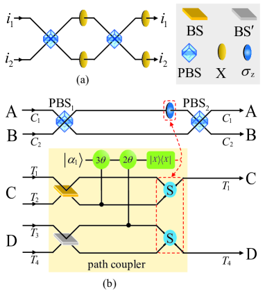
The SWAP gate (abbreviated as S), depicted in Fig. 1 (a), serves two functions. The one is to exchange two paths of a single photon and the other one is to swap the polarized states of two photons. In detail, suppose that two photons AB are initially in the following state
where and the complex coefficients conform to the normalization principle, i.e., and . After two photons AB pass through the optical elements PBSs and Xs, the parallel transformation can be obtained
Based on Eq. (II.1), the quantum circuit unequivocally swaps the polarized states of two photons AB only with simple linear-optics elements. Additionally, the S has another function, which can swap two paths of a single photon, as the single photon enters from the up (down) path () and then exits from the down (up) one ().
II.2 Path coupler
A path coupler shown in Fig. 1(b), called a quantum eraser, combines two paths into one, making halve the number of the paths without destroying the polarization information of the photon. Suppose that the state of two photons AB to encode a logic qubit and the state of two photons CD to encode another logic qubit in DFS are
| (4) |
where the complex coefficients conforms to the normalization principle, i.e., . Four photons ABCD are initially prepared in the arbitrary state
| (5) | |||||
Firstly, photons AB pass through , meanwhile photons C and D pass through and , respectively. After interacting with the coherent state via Kerr media, the process can be expressed as
| (6) | |||||
After following the X-Homodyne measurement, we induce four measurement outcomes, i.e., phase shifts , , and . If the outcome is zero phase shift, the state of the whole system becomes into
| (7) |
If the outcome is another case, corresponding feed-forward operations shown in Table 1 must be performed based on the measurement outcomes to get the desirous state in Eq. (7). In Table 1, () represents the paths of photons C (or D) to remain unchanged, () mean to swap two paths of the photon C (or D) with the S in Fig. 1 (a), and performs the phase-flip operation from the path .
Finally, photons AB pass through the second , resulting in the final state
| (8) |
That is, the path coupler merges two paths and ( and ) into the one () with the above device, and likewise, as the quantum circuit in Fig. 1 (a) is universal and flexible, the merging of other paths we desired can be obtained by suitable feed-forward operations, such as and ( and ) are merged into the path (). Similarly, when the initial state of two photons CD to encode logic qubit in DFS is , by replacing with in Eq. (5), we also obtain the same appearance.
|
Single-qubit operations | |||
|---|---|---|---|---|
| 0 | ||||
III Quantum logical gate
III.1 CNOT gate
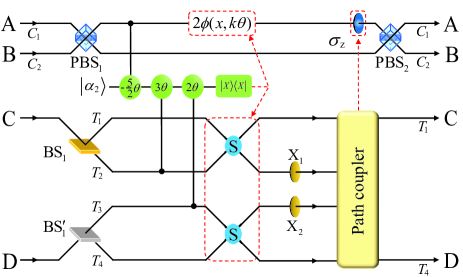
Suppose that the initial state of two logical qubits in DFS is , where the quantum state of control logical qubit AB and that of target logical qubit CD are the same as those in Eq. (II.2). The quantum circuit for implementing the CNOT gate is shown in Fig. 2. Firstly, the control photons AB pass through , meanwhile the target photons C and D pass through and , respectively. Then, four photons combine with the coherent state with the help of the cross-Kerr nonlinearity, resulting in the quantum state changed into the state
| (9) | |||||
As the X-Homodyne measurement cannot distinguish between phase shift and phase shift , we obtain four different scenarios of phase shifts . A phase modulation , a function of the phase shift and the eigenvalue of the X-Homodyne operator, is performed to erase the phase difference between the two superposition terms in the scenarios of three different nonzero phase shifts. If the outcome is zero phase shift, the state of the whole system becomes into
| (10) | |||||
By performing corresponding feed-forward operations for the other measurement outcomes, as shown in Table 2, we can get the state with the success probability close to unit.
|
Phase modulation | Single-qubit operations | |||
|---|---|---|---|---|---|
| 0 | 0 | ||||
Next, the target photons CD pass through and , respectively, and the evolution of the system can be illustrated as follows
| (11) | |||||
Finally, the control photons AB pass through and the target photons CD pass through the path coupler in Fig. 1(b), merging two paths and ( and ) into one path () of the target photon C (D), the quantum state is evolved as
It is obvious that the result of the CNOT gate flips the state of the target photons CD if and only if the control photons AB is in the state , and has no change otherwise.
III.2 Toffoli gate
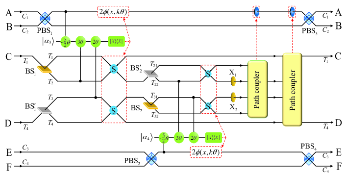
The quantum circuit of the three-logic-qubit Toffoli gate composed of six photons in Fig. 3, where the initial state of the second control qubit encoded by two photons EF in DFS is . Firstly, the control photons AB and the target ones CD perform the same operations as the first step of two-logic-qubit CNOT gate in Fig. 2. By performing corresponding feed-forward operations as shown in Table 2, we can get quantum state with the same form in Eq. (10) with the success probability close to unit.
Secondly, the second control photons EF enter into , meanwhile the target photons CD enter into and , and their evolution interacting with the coherent state via Kerr media can be expressed as
| (13) | |||||
After performing the X-Homodyne measurement on the coherent state , we once again obtain four sets of measurement outcomes, and corresponding feed-forward operations shown in Table 3 are executed based on the measurement outcomes, resulting in the quantum state collapses into
|
Phase modulation | Single-qubit operations | |||
|---|---|---|---|---|---|
| 0 | 0 | ||||
Thirdly, the target photons C and D pass through and , respectively. The evolution of the system can be illustrated as follows
Fourthly, the target photons CD pass through the first path coupler in Fig. 1(b), merging two paths and ( and ) into one (), and the quantum state becomes into
Finally, the target photons qubits CD pass through the second path coupler again, merging paths and ( and ) into paths (), and meanwhile the control photons AB and EF pass through and , respectively, resulting into
| (17) | |||||
Apparently, based on Eq. (17) the three-logic-qubit Toffoli gate encoding with six photons ABCDEF in DFS is fulfilled perfectly with the success probability close to unit, by performing appropriate feed-forward operations in Tables 1-3, where the Toffoli gate flips the states of the target photons CD if and only if the control photons AB and EF are both in the state , and has no change otherwise.
III.3 Fredkin gate
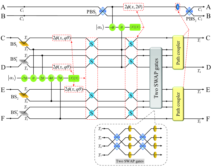
The quantum circuit of the three-logic-qubit Fredkin gate is depicted in Fig. 4, where the initial states of three logical qubits are the same as the one of the Toffoli gate, with four photons CD and EF serving as two target logical qubits and photons AB as a unique control logical qubit. Firstly, four target photons CDEF traverse , , , and , respectively, and then undergo the cross-Kerr nonlinearity. The evolution of system is illustrated by
| (18) | |||||
If the outcome is zero phase shift, the state of the composite system can be denoted as
| (19) | |||||
Otherwise, nonzero phase shifts are obtained. The phase shift operation should be performed, along with the corresponding feed-forward single-qubit operations as shown in Table 4 to achieve the desired state in Eq. (19).
|
Phase modulation | Single-qubit operations | |||
|---|---|---|---|---|---|
| 0 | 0 | ||||
Secondly, the control photons AB traverse , and the evolution process of they interacting with the coherent state is expressed as
If no phase shift is induced in the coherent state , there is nothing to do. However, if a phase shift of is induced, a feed-forward operation is applied on path , followed by four SWAP gates applied on some paths , , and . Then, the finally state is given by
| (21) | |||||
Thirdly, two SWAP gates are executed on the target photons CE on two paths and the target photons DF on two paths , respectively, and the quantum state is evolved into
| (22) | |||||
where
| (23) |
Finally, the control photons AB traverse and the target photons CD and EF traverse two path couplers in Fig. 1(b) to simplify the circuits, respectively, and the desirous state is obtained
| (24) | |||||
Apparently, based on Eq. (24), the three-logic-qubit Fredkin gate encoding with six photons ABCDEF in DFS is fulfilled perfectly with the success probability close to unit, by performing appropriate feed-forward operations in Tables 1 and 4, where the Fredkin gate swaps the states of the target photons CD and EF if and only if the control photons AB is in the state , and has no change otherwise.
IV Success probabilities and fidelities of quantum gates regard to photon loss
In view of cross-Kerr nonlinearities, the principles of three schemes for CNOT, Toffoli, and Fredkin gates in DFS to overcome decoherence, are discussed in detail in Sec. III. Besides, the path couplers of three quantum logical gates are employed to simplify the complexity of quantum circuits and halve the number of the paths of the photons without destroying the polarization information of these photons. As the cosine function conforming to cannot differentiate between positive phase shift and negative phase shift of the coherent states, the X-homodyne measurement can obtain four scenarios of phase shifts, i.e., from the corresponding coherent states and for implementation of the path couplers, two-logic-qubit CNOT gate, and three-logic-qubit Toffoli gate. It can also distinguish eight scenarios of phase shifts, i.e., from the coherent states and two scenarios of phase shifts, i.e., from the coherent state for implementation of the three-logic-qubit Fredkin gate. Next, we analyze the success probabilities and fidelities of our quantum gates.
IV.1 Success probabilities of quantum gates regard to photon loss
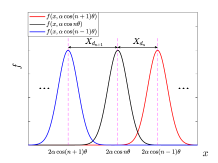
The success probabilities of the our protocols relies on the precise measurement of the X-quadrature homodyne. The Gaussian function curves and partially overlap, resulting in errors between phase shifts and shown in Fig. 6 (a). The photon loss of the probe coherent field in the nonlinear medium leads to . where is the decay constant and is the coherence parameter reducing the amplitude of coherent state and making the original pure state to evolve into a mixed state of the photons. Considering the photon dissipation of the coherent state, the success probability can be calculated by
| (25) |
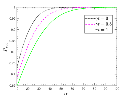
where erfc(x) is a Gauss complementary error function and the success probabilities are depicted in Fig. 5 (b) with the amplitude under the different conditions , , and , respectively. If the amplitude of the coherent state increases and dissipation coefficient decreases, the success probabilities of our schemes increase. By calculation with the different parameters of Ref. Lin and Li (2009); Dong et al. (2018), six sets of data are obtained, e.g., , , , , , and . Based on the analyses above, the nearly deterministic quantum logical gates, i.e., CNOT, Toffoli, and Fredkin gates in DFS, can be achieved.
In the above discussion about the success probabilities of the our protocols, we only investigate the errors mainly resulting from the overlap of adjacent curves without considering other conditions. Whereas, the strength of natural cross-Kerr nonlinearity Kok et al. (2007) is so small that it can not provide effective interactions between photons, which leads to increasing the difficulty in distinguishing two overlapping coherent states, decreasing the success probability of the path coupler and three gates. Fortunately, various physical systems or synthetic media, such as negative-index metamaterials Siomau et al. (2012), a superconducting artificial atom Hoi et al. (2013b), and a three-dimensional quantum electrodynamic architectures Paik et al. (2011); Kirchmair et al. (2013), have been explored to achieve stronger cross-Kerr nonlinearities. Besides, phase shift, another factor that affects success probability, can be increased by prolonging the interaction time of photons and coherent state Lukin and Imamoğlu (2000); Bajcsy et al. (2003); Wang et al. (2006); Chen et al. (2012), as well as measurement-based methods Jeong (2006); Feizpour et al. (2011); Sefi et al. (2013) and quadrature squeezing operations Bartkowiak et al. (2014) to achieve large phase shift. By employing a two-level atom in a one-sided cavity and the displacements-controlled photon number resolving (PNR) detector, accomplished phase shift can be obtained Hofmann et al. (2003). Thus, in the case , one can realize the deterministic distinguishability between the shifted and non-shifted phases in the coherent state, where the cross-Kerr nonlinearities with a sufficiently large amplitude of the coherent states would be applicable. Furthermore, two coherent states can be discriminated to lower the error probability, resorting to a homodyne detector and a PNR detector applying the postselection strategy Wittmann et al. (2010). Therefore, we set up the CNOT, Toffoli and Fredkin gates in DFS based on Kerr effect, which can overcome and alleviate the disadvantageous factors, ultimately reducing the error probabilities.
IV.2 Fidelities of our quantum gates regard to photon loss
The coupling between the coherent state and environment causes the loss of photons of the coherent state, so we consider the influence of photon loss on fidelity. The decoherence effects for the coherent state described by the standard master equation
| (26) |
where and are the annihilation and creation operators of the coherent state, respectively. denotes the density matrix of the system. The formal solution of the master Eq. (26) can be written as and is the interaction time. The evolution of the hybrid system caused by nonlinear interactions between the photons and the coherent states could be described by a unitary evolution equation . Assumed that the interaction time is defined on the temporal interval and is divided into parts (), setting , the decoherence process occurs for a short time and the unitary evolution operator occurs for next temporal interval (). After the finite temporal interval , the system would evolve as .
As four scenarios of phase shifts, i.e., , , , from the corresponding coherent states and for implementation of the path couplers, two-logic-qubit CNOT gate, and three-logic-qubit Toffoli gate, and eight scenarios of phase shifts, i.e., , , from the coherent states for implementation of the three-logic-qubit Fredkin gate can be obtained by the X-homodyne measurements. We take the fidelity the CNOT gate as an example to denote. The initial state is in Eq. (9), that is, the density matrix of the initial system is , due to the decoherence effects, which can be rewritten as
Here,
| (28) |
where is the normalization coefficient. Interacting with the probe mode via weak cross-Kerr nonlinearity, the hybrid system is changed to
| (29) | |||||
where . After performing X measurement on the dissipated coherent state, the resulting state can be obtained as follows
| (30) | |||||
where and .
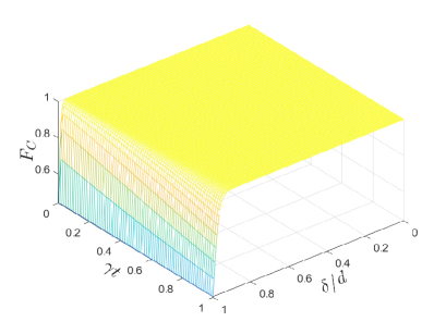
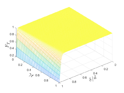
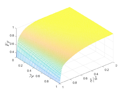
Based on the fidelity formula determined by the real output state and the ideal one, the fidelity versus dissipation term as well as with the dimensionless parameters set as and Hoi et al. (2013a) are plotted in Fig. 6. is the distance between measurement point and peak. is the distance between the two peaks, which increases leads to the reduction of overlap between the two Gauss functions. It can be seen that the fidelities , , and decrease with the increasing and the reducing coefficient . By calculation with the different parameters of Ref. Lin and Li (2009); Dong et al. (2018), four sets of data are obtained, e.g., , , , ; , , , ; , , , . Based on the analyses above, the high fidelities of quantum logic gates in DFS can be achieved even though under the decoherence environment.
V SUMMARY
In summary, with the help of the cross-Kerr nonlinearities, we propose the effectuation of the nearly deterministic two-logic-qubit CNOT gate, three-logic-qubit Toffoli gate, and Fredkin gate encoded on polarization degrees of freedom of photon systems due to the significant features, e.g., the low-decoherence character, flexible single-qubit manipulation, and ultra-fast transmission. Moreover, the SWAP gates and the path couplers are innovated for implementing three logical gates. The SWAP gate, which serves to swap the polarized states of two photons as well as two paths of a single photon, is set up with simple linear-optics elements, so its success probability is unit, The path coupler with the probability near close to unit is utilized to combine two paths of the photon to the one by available single-qubit operations and mature measurement methods, which halves the number of the paths of the photon and greatly simplifies the quantum circuits. Therefore, these three logical gates require neither complicated quantum computational circuits nor auxiliary photons (or entangled states). Further, the success probabilities of three logical gates are approximate unit by performing the corresponding classical feed-forward operations based on the different measuring results of the X-homodyne detectors to be aimed at the coherent states. Eventually, their fidelities are robust against the photon loss with the current technology. The proposed schemes play positive roles in the future development of QIP owing to the robust feature by resisting the influence of decoherence effect in DFS.
Acknowledgments
This work was supported in part by the Natural Science Foundation of China under Contract 61901420; in part by the Shanxi Province Science Foundation for Youths under Contract 201901D211235; in part by the Scientific and Technological Innovation Programs of Higher Education Institutions in Shanxi under Contract 2019L0507.
Disclosures
The authors declare that there are no conflicts of interest related to this article.
Data Availability
Data underlying the results presented in this paper are not publicly available at this time but may be obtained from the authors upon reasonable request.
References
- Nielsen and Chuang (2002) M. A. Nielsen and I. Chuang, Am. J. Phys. 70, 558 (2002).
- Huo and Li (2023) M. Huo and Y. Li, Quantum 7, 916 (2023).
- Hayashi and Yang (2023) M. Hayashi and Y. Yang, Quantum 7, 936 (2023).
- Luo et al. (2020) X. Luo, J. Liu, P. Zhang, and L. Wang, Quantum 4, 341 (2020).
- Wang et al. (2021) X. Wang, Z. Song, and Y. Wang, Quantum 5, 483 (2021).
- Long and Liu (2002) G. L. Long and X. S. Liu, Phys. Rev. A 65, 032302 (2002).
- Zhang et al. (2017) W. Zhang, D. S. Ding, Y. B. Sheng, L. Zhou, B. S. Shi, and G. C. Guo, Phys. Rev. Lett. 118, 220501 (2017).
- Zhu et al. (2017) F. Zhu, W. Zhang, Y. Sheng, and Y. Huang, Sci. Bull. 62, 1519 (2017).
- Li and Long (2020) T. Li and G. L. Long, New J. Phys. 22, 063017 (2020).
- Huang et al. (2021) Z. Huang, P. P. Rohde, D. W. Berry, P. Kok, J. P. Dowling, and C. Lupo, Quantum 5, 447 (2021).
- Wang (2021) C. Wang, Fundam. Res. 1, 91 (2021), ISSN 2667-3258.
- Qi et al. (2021) Z. Qi, Y. Li, Y. Huang, J. Feng, Y. Zheng, and X. Chen, Light Sci. Appl. 10, 183 (2021).
- Long and Zhang (2021) G. L. Long and H. Zhang, Sci. Bull. 66, 1267 (2021).
- Sheng et al. (2022) Y. B. Sheng, L. Zhou, and G. L. Long, Sci. Bull. 67, 367 (2022).
- Zhang et al. (2022) H. Zhang, Z. Sun, R. Qi, L. Yin, G. L. Long, and J. Lu, Light Sci. Appl. 11, 83 (2022).
- Fiurášek (2008) J. Fiurášek, Phys. Rev. A 78, 032317 (2008).
- Dell’Anno et al. (2006) F. Dell’Anno, S. De Siena, and F. Illuminati, Phys. Rep. 428, 53 (2006).
- Liu and Wei (2020) W. Q. Liu and H. R. Wei, New J. Phys. 22, 063026 (2020).
- Liu et al. (2020) W. Q. Liu, H. R. Wei, and L. C. Kwek, Phys. Rev. Appl. 14, 054057 (2020).
- Nemoto and Munro (2004) K. Nemoto and W. J. Munro, Phys. Rev. Lett. 93, 250502 (2004).
- Lin and Li (2009) Q. Lin and J. Li, Phys. Rev. A 79, 022301 (2009).
- Lin and He (2009) Q. Lin and B. He, Phys. Rev. A 80, 042310 (2009).
- Wang et al. (2012) X. W. Wang, D. Y. Zhang, S. Q. Tang, L. J. Xie, Z. Y. Wang, and L. M. Kuang, Phys. Rev. A 85, 052326 (2012).
- Dong et al. (2018) L. Dong, S. L. Wang, C. Cui, X. Geng, Q. Y. Li, H. K. Dong, X. M. Xiu, and Y. J. Gao, Opt. Lett. 43, 4635 (2018).
- Wei and Deng (2013) H. R. Wei and F. G. Deng, Phys. Rev. A 88, 042323 (2013).
- Ai et al. (2021) Q. Ai, P.-B. Li, W. Qin, J.-X. Zhao, C. P. Sun, and F. Nori, Phys. Rev. B 104, 014109 (2021).
- Wu et al. (2022) Y.-M. Wu, G. Fan, and F.-F. Du, Frontiers of Physics 17, 51502 (2022).
- Wei and Deng (2014) H. R. Wei and F. G. Deng, Opt. Express 22, 593 (2014).
- Wei et al. (2020) H. R. Wei, Y. B. Zheng, M. Hua, and G. F. Xu, Appl. Phys. Express 13, 082007 (2020).
- Han et al. (2021) Y. H. Han, C. Cao, L. Fan, and R. Zhang, Opt. Express 29, 20045 (2021).
- Song et al. (2021) G. Z. Song, J. L. Guo, Q. Liu, H. R. Wei, and G. L. Long, Phys. Rev. A 104, 012608 (2021).
- Li et al. (2019) T. Li, A. Miranowicz, K. Xia, and F. Nori, Phys. Rev. A 100, 052302 (2019).
- Song et al. (2022) G. Z. Song, M. J. Tao, J. Qiu, and H. R. Wei, Phys. Rev. A 106, 032416 (2022).
- Du and Shi (2019) F. F. Du and Z. R. Shi, Opt. Express 27, 17493 (2019).
- Arute et al. (2019) F. Arute, K. Arya, R. Babbush, D. Bacon, J. C. Bardin, R. Barends, R. Biswas, S. Boixo, F. G. Brandao, D. A. Buell, et al., Nature 574, 505 (2019).
- Duan and Guo (1997) L. M. Duan and G. C. Guo, Phys. Rev. Lett. 79, 1953 (1997).
- Wei et al. (2008) H. Wei, W. L. Yang, Z. J. Deng, and M. Feng, Phys. Rev. A 78, 014304 (2008).
- Deng et al. (2007) Z. J. Deng, M. Feng, and K. L. Gao, Phys. Rev. A 75, 024302 (2007).
- Chen et al. (2022a) L. Chen, X. M. Xiu, L. Dong, S. Zhang, S. L. Su, S. Chen, and E. J. Liang, Ann. Phys. 534, 2100365 (2022a).
- Chen et al. (2022b) L. Chen, X. M. Xiu, L. Dong, N. N. Liu, C. P. Shen, S. Zhang, S. Chen, and S. L. Su, Opt. Lett. 47, 2262 (2022b).
- Wei et al. (2007) H. Wei, Z. Deng, X. Zhang, and M. Feng, Phys. Rev. A 76, 054304 (2007).
- Hoi et al. (2013a) I. C. Hoi, A. F. Kockum, T. Palomaki, T. M. Stace, B. Fan, L. Tornberg, S. R. Sathyamoorthy, G. Johansson, P. Delsing, and C. M. Wilson, Phys. Rev. Lett. 111, 053601 (2013a).
- Kok et al. (2007) P. Kok, W. J. Munro, K. Nemoto, T. C. Ralph, J. P. Dowling, and G. J. Milburn, Rev. Mod. Phys. 79, 135 (2007).
- Siomau et al. (2012) M. Siomau, A. A. Kamli, S. A. Moiseev, and B. C. Sanders, Phys. Rev. A 85, 050303 (2012).
- Hoi et al. (2013b) I. C. Hoi, A. F. Kockum, T. Palomaki, T. M. Stace, B. Fan, L. Tornberg, S. R. Sathyamoorthy, G. Johansson, P. Delsing, and C. M. Wilson, Phys. Rev. Lett. 111, 053601 (2013b).
- Paik et al. (2011) H. Paik, D. I. Schuster, L. S. Bishop, G. Kirchmair, G. Catelani, A. P. Sears, B. R. Johnson, M. J. Reagor, L. Frunzio, L. I. Glazman, et al., Phys. Rev. Lett. 107, 240501 (2011).
- Kirchmair et al. (2013) G. Kirchmair, B. Vlastakis, Z. Leghtas, S. E. Nigg, H. Paik, E. Ginossar, M. Mirrahimi, L. Frunzio, S. M. Girvin, and R. J. Schoelkopf, Nature 495, 205 (2013).
- Lukin and Imamoğlu (2000) M. D. Lukin and A. Imamoğlu, Phys. Rev. Lett. 84, 1419 (2000).
- Bajcsy et al. (2003) M. Bajcsy, A. S. Zibrov, and M. D. Lukin, Nature 426, 638 (2003).
- Wang et al. (2006) Z. B. Wang, K. P. Marzlin, and B. C. Sanders, Phys. Rev. Lett. 97, 063901 (2006).
- Chen et al. (2012) Y. H. Chen, M. J. Lee, W. Hung, Y. C. Chen, Y. F. Chen, and I. A. Yu, Phys. Rev. Lett. 108, 173603 (2012).
- Jeong (2006) H. Jeong, Phys. Rev. A 73, 052320 (2006).
- Feizpour et al. (2011) A. Feizpour, X. Xing, and A. M. Steinberg, Phys. Rev. Lett. 107, 133603 (2011).
- Sefi et al. (2013) S. Sefi, V. Vaibhav, and P. van Loock, Phys. Rev. A 88, 012303 (2013).
- Bartkowiak et al. (2014) M. Bartkowiak, L. A. Wu, and A. Miranowicz, Journal of Physics B: Atomic, Molecular and Optical Physics 47, 145501 (2014).
- Hofmann et al. (2003) H. F. Hofmann, K. Kojima, S. Takeuchi, and K. Sasaki, Journal of Optics B: Quantum and Semiclassical Optics 5, 218 (2003).
- Wittmann et al. (2010) C. Wittmann, U. L. Andersen, M. Takeoka, D. Sych, and G. Leuchs, Phys. Rev. A 81, 062338 (2010).