Engineering flat bands in twisted-bilayer graphene
away from the magic angle with chiral optical cavities
Abstract
Twisted bilayer graphene (TBG) is a recently discovered two-dimensional superlattice structure which exhibits strongly-correlated quantum many-body physics, including strange metallic behavior and unconventional superconductivity. Most of TBG exotic properties are connected to the emergence of a pair of isolated and topological flat electronic bands at the so-called magic angle, , which are nevertheless very fragile. In this work, we show that, by employing chiral optical cavities, the topological flat bands can be stabilized away from the magic angle in an interval of approximately . As highlighted by a simplified theoretical model, time reversal symmetry breaking, induced by the chiral nature of the cavity, plays a fundamental role in flattening the isolated bands and gapping out the rest of the spectrum. The efficiency of the cavity is discussed as a function of the twisting angle, the light-matter coupling and the optical cavity characteristic frequency. Our results demonstrate the possibility of engineering flat bands in TBG using optical devices, extending the onset of strongly-correlated topological electronic phases in Moiré superlattices to a wider range in the twisting angle.
Introduction – Controlling and engineering quantum phases of matter is a central task in condensed matter physics. Inspired by the original discovery of single-layer graphene Novoselov et al. (2004), two-dimensional (2D) materials have emerged as a versatile platform to realize strongly-correlated physics in quantum many body systems Novoselov et al. (2016). Recently, unconventional superconductivity was discovered in twisted bilayer graphene (TBG), a two dimensional superlattice where one layer of graphene is stacked on top of another at a special magic twisting angle, i.e., Cao et al. (2018a); Yankowitz et al. (2019); Lu et al. (2019); Saito et al. (2020). Galvanized by this breakthrough, several other stacked two-dimensional systems that host exotic superconductivity, such as twisted multilayer graphene, have been revealed Chen et al. (2019a, b); Park et al. (2021); Zhang et al. (2021); Park et al. (2022a). While the underneath physical mechanism of superconductivity in twisted 2D systems is still under debate Po et al. (2018); Isobe et al. (2018); Wu et al. (2018); Xu and Balents (2018); Xie et al. (2020); Song and Bernevig (2022); Liu et al. (2018); Roy and Juričić (2019), it is clear that the isolated electronic flat band appearing at the magical angle plays an essential role. Besides superconductivity, flat bands are also indispensable for the emergence of strongly-correlated insulating states and the strange-metal phase near the superconducting dome in the phase diagram of TBG, which closely mimics that of cuprate superconductors Cao et al. (2018b, 2020); Liu et al. (2021); Xie and MacDonald (2020); Koshino et al. (2018); Dodaro et al. (2018); Yuan and Fu (2018); Thomson et al. (2018); Pizarro et al. (2019).
However, despite being a promising platform for studying strongly correlated physics, the unavoidable and uncontrollable non-uniformity of the twist angle across the sample, and the consequent difficulty in keeping the twist angle at its magic value, prevented a wide realization of these phenomena Park et al. (2022b); Wilson et al. (2020). More precisely, because the magical-angle configuration is unstable, a little offset (around ) of the twisting angle easily destroys all the emergent exotic properties of TBG. In this regard, one of the most important challenges in the field is therefore to achieve superconductivity at non-magic values of the twisting angle. To achieve this final goal, it is desirable to realize a primary step, namely to create and stabilize electronic flat bands in a wider range of the twisting angle Bi et al. (2019); Choi and Choi (2019); Liu et al. (2020); Sboychakov et al. (2018); Wolf et al. (2019).
In this Letter, we propose a new method to engineer stable flat bands at non-magic angles by embedding twisted-bilayer graphene in a vacuum chiral cavity (see top panel in Figure 1 for a cartoon of the setup). Using vacuum cavities to control materials and molecules has emerged as a fruitful playground connecting quantum optics to condensed matter and chemistry Hübener et al. (2021); Schlawin et al. (2022); Bloch et al. (2022); Schäfer et al. (2018). Vacuum cavity engineering is superior to the Floquet method, where external electromagnetic radiation drives the system out of equilibrium, since this second route inevitably heats up the system, destroying quantum coherence and inducing transient phenomena away from thermal equilibrium states. In the past, the usage of vacuum cavities has been proposed to design material conductivity Rokaj et al. (2022); Moddel et al. (2021), unconventional superconductivity Sentef et al. (2018); Schlawin et al. (2019); Curtis et al. (2019); Thomas et al. (2019), topological properties Espinosa-Ortega et al. (2014); Wang et al. (2019); Appugliese et al. (2022), and even chemical reactivity Galego et al. (2019, 2015). Some of these proposals have been already successfully realized experimentally.
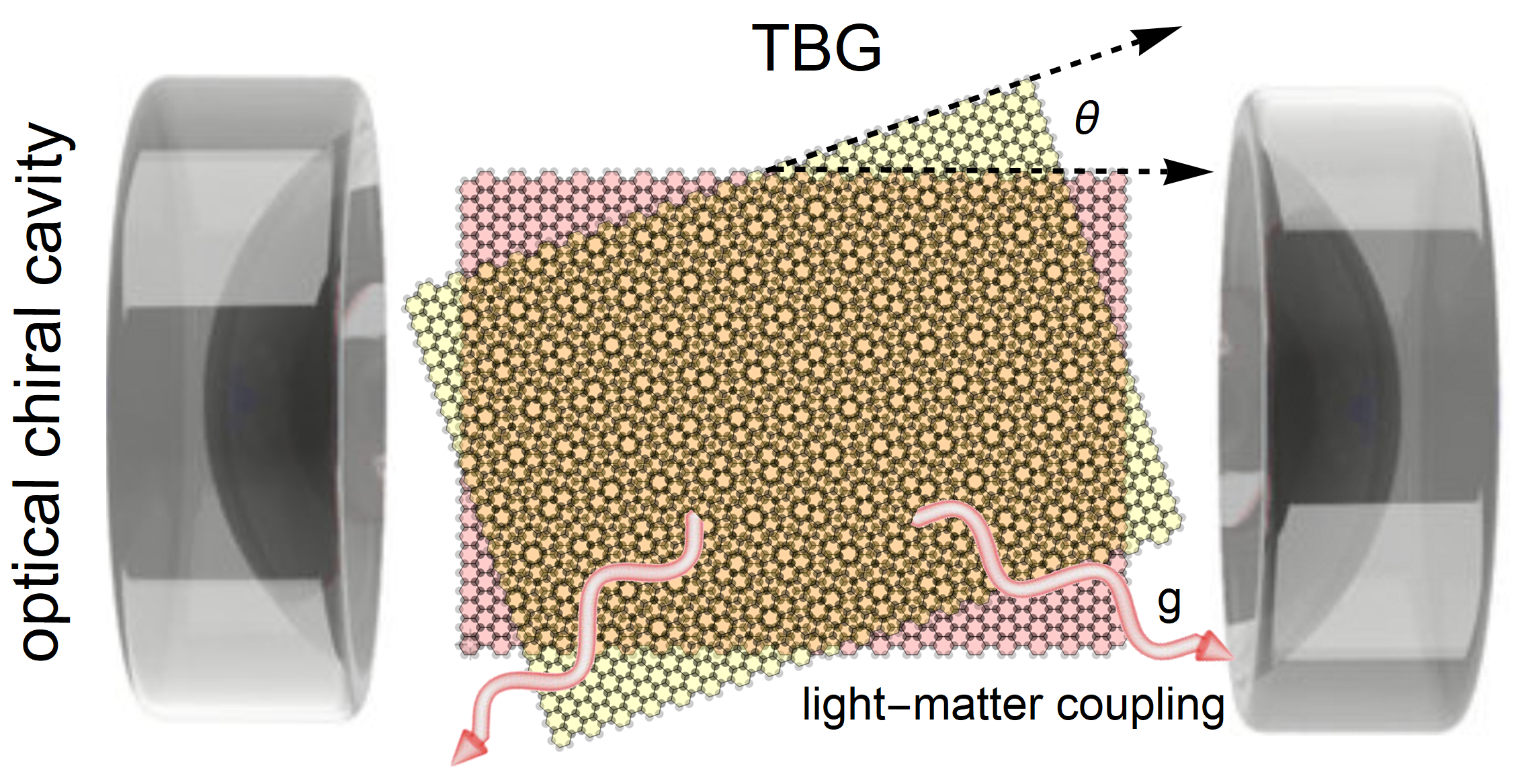
A fundamental property of vacuum chiral cavities is that time-reversal symmetry is broken without the need of an external driving. Time-reversal symmetry breaking is essential since, as we will see, quantum fluctuations alone can not significantly influence the electronic bands in TBG. In single-layer graphene, a band gap can be induced by quantum fluctuations in a chiral cavity as well Wang et al. (2019). However, the effect is too small to be directly observed due to the large bandwidth. As we will demonstrate, the situation is different in TBG near the magic angle, where the small bandwidth enables time-reversal symmetry-broken quantum fluctuations to play a significant role.
In recent years, a number of works have realized the vital impact of symmetry breaking on quantum-fluctuations-related phenomena, such as anomalous Casimir effects Butcher et al. (2012); Jiang and Wilczek (2019a), topological gap generation Espinosa-Ortega et al. (2014); Wang et al. (2019), and selection of chiral molecules in chemical reactions Ke et al. (2022); Riso et al. (2022). A recent work by one of us Jiang and Wilczek (2019b) highlighted the combined power of symmetry breaking and quantum fluctuations, proving that symmetry breaking effects can be transmitted from a material to its vicinity by vacuum quantum fluctuations. In this scenario, the vacuum in proximity of a material with broken symmetries is referred to as its Quantum Atmosphere.
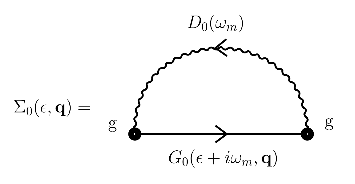
In this Letter, we investigate the band renormalization of TBG in the time-reversal symmetry broken quantum atmosphere provided by a chiral cavity. We start from a faithful tight-binding model of TBG and calculate the one-loop self-energy induced by the light-matter coupling. The bottom panel of Figure 1 displays the specific Feynman diagram considered. We find that, for experimentally realizable values of the light-matter coupling and cavity frequency, the topological flat bands in TBG can be stabilized away from the magic angle in an interval of approximately . Our derivation and calculations can be directly generalized to other twisted 2D systems.
Setup and methods – To set the stage, we model the Hamiltonian of the combined system, TBG and cavity, as follows:
| (1) |
where represents the TBG Hamiltonian in reciprocal space, and is the cavity photonic mode frequency. TBG and cavity photonic modes are coupled through Peierls substitution , where can be expressed in terms of photonic creation and annihilation operators, i.e., . Here, is the polarization tensor of the cavity photonic modes and is the mode amplitude in terms of the cavity volume . We focus on chiral cavities where the photonic polarization is given by , with the unit vector in the x(y)-direction. Our setup can be straightforwardly generalized to the multi-mode case.
To be concrete, let us consider the effective tight-binding Hamiltonian Catarina et al. (2019):
| (2) |
where is the wave-vector, and indicate the Hamiltonian of the top/bottom layer respectively. Moreover, we have defined:
| (3) |
where and are Moiré reciprocal vectors. The twisting angle is hidden in these vectors; see Fig.6.11 in Ref.Catarina et al. (2019) for more details. The hopping matrix elements are given by,
| (4) |
where and is the hopping parameter. For more details about the TBG Hamiltonian we refer to the Supplementary Information (SI). Once the effective Hamiltonian is known, the bare electron propagator can be obtained using Wang et al. (2019)
| (5) |
The full electron propagator, taking into account the interaction with the vacuum cavity, can then be derived from the Dyson equation
| (6) |
where is the self-energy (see bottom panel of Fig.1) given by
| (7) |
Here, is the th Matsubara frequency and denotes the electron-photon coupling strength with the Fermi velocity of monolayer graphene and the electromagnetic coupling. Finally, is the photon propagator given by
| (8) |
with the cavity frequency. It should be noticed here that all quantities , , , are matrices with the same dimension of the effective TBG Hamiltonian. With the full propagator in Eq.(6), the spectral function, giving the renormalized electronic band structure, can be calculated from
| (9) |
More details about the TBG Hamiltonian, the structure in reciprocal space and the numerical methods employed can be found in the SI. In the rest of this manuscript, we will be mainly interested in studying the electronic spectral function as a function of the twisting angle , the light-matter coupling and the cavity frequency . For convenience, we define the dimensionless coupling .
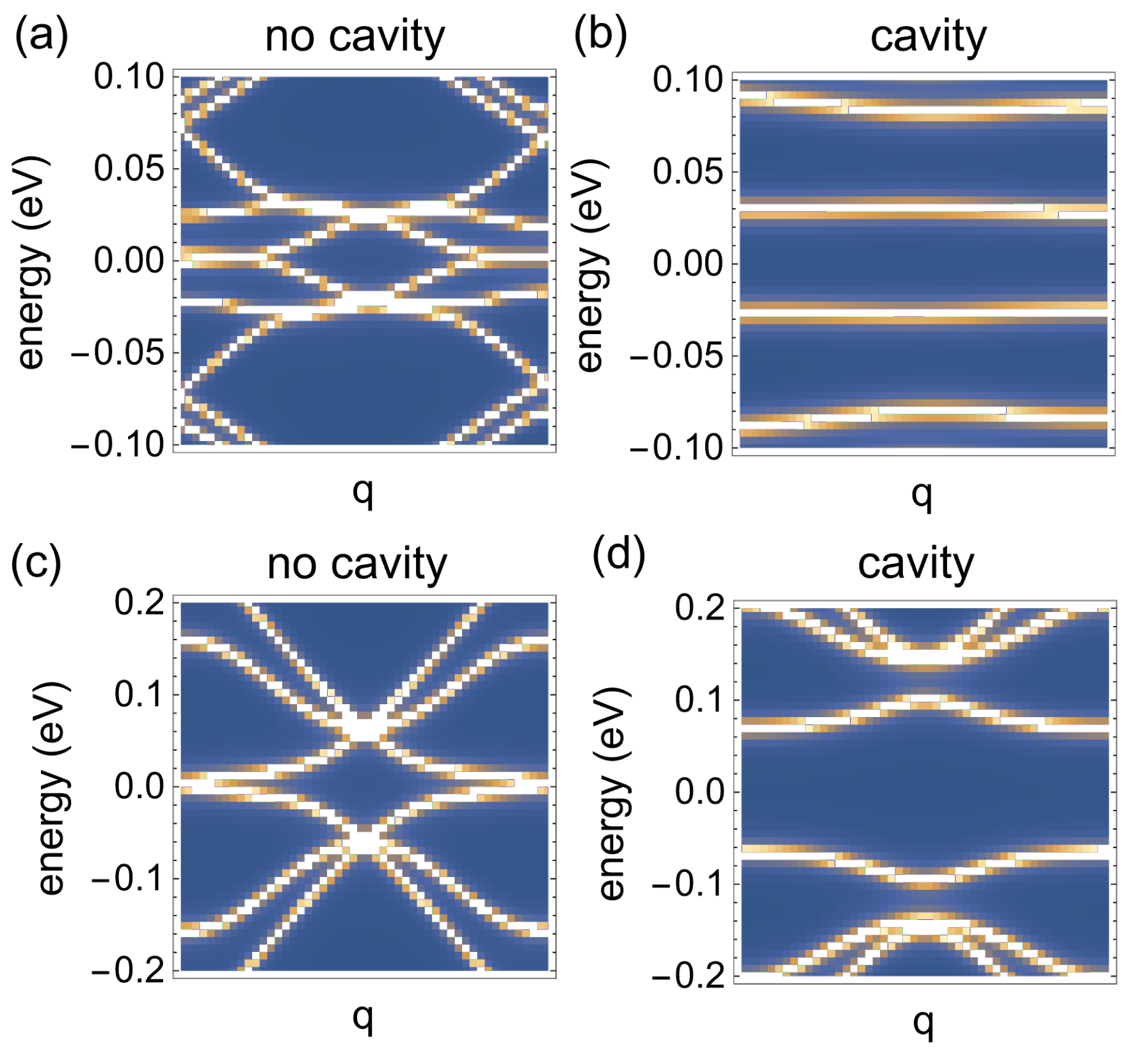
Electronic spectrum – It is well known that TBG exhibits a pair of topological flat bands at the magic angle, Bistritzer and MacDonald (2011); Suárez Morell et al. (2010); Andrei and MacDonald (2020), which play a key role for the underlying strongly-correlated physics. Away from that magic value, the flat bands, and most of the exotic and interesting related properties of TBG, disappear. In panels (a) and (c) of Fig.2, we show two examples of the electronic spectrum of TBG at respectively and . As already mentioned, no isolated flat bands are present anymore in the electronic spectrum just moving of from the magic angle. In other words, the flat bands are very fragile and sensitive to the twisting angle. In panels (b) and (d) of Fig.2, we show the same electronic spectra in presence of the chiral optical cavity, with a coupling and a characteristic frequency eV. A pair of nearly-flat bands re-appear away from the magic angle thanks to the coupling to the chiral cavity. Importantly, the two bands are not anymore degenerate as their energy is shifted from the Fermi energy and grows with the light-matter coupling . This is a direct consequence of the breaking of time reversal symmetry induced by the chiral cavity. At the same time, the other bands, similarly to the case of the Dirac cone in monolayer graphene (see SI), are also gapped away as a consequence of the same symmetry breaking pattern.
Theoretical model – The emergence of the two isolated quasi-flat bands and their energy splitting, shown in Fig.2, are intimately connected to the chiral nature of the optical cavity, which plays a fundamental role in this regard. To explicitly prove this statement we construct a simplified analytical model which, as we will see, possesses all the minimal ingredients to describe our setup. In order to model the effects of the chiral cavity on TBG, we consider the following deformed hamiltonian
| (10) |
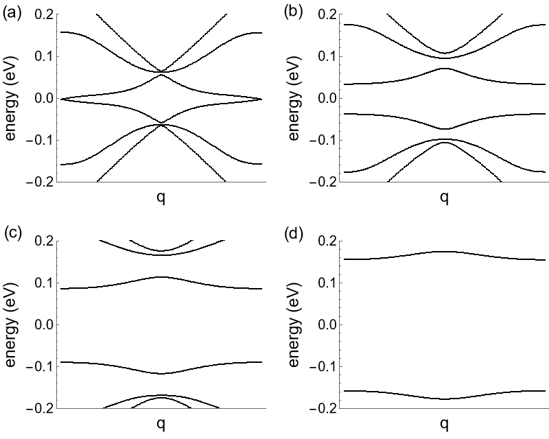
where the coupling parameterizes the breaking of time-reversal symmetry on top of the original TBG Hamiltonian in Eq.(2). This is unlikely the most general deformation which breaks time-reversal symmetry, but it will be sufficient to qualitatively reproduce the numerical results displayed in Fig.2 and identify the main underlying physical principle behind them. By diagonalizing the above Hamiltonian , the band structure with broken time reversal symmetry can be obtained. The results are shown in Fig.3 for different strength of the time-reversal symmetry breaking . As clearly demonstrated, the effects of is to gap away the higher energy bands and create a pair of isolated quasi-flat bands wth non-degenerate energy. At least at a qualitative level, these results are in perfect agreement with the more realistic scenario of TBG in a chiral cavity shown in Fig.2, where the light-matter coupling plays an analogous role of the phenomenological parameter in Eq.(10). This simplified but tractable analytical model highlights the fundamental role of time reversal symmetry breaking, induced by the chiral cavity, in stabilizing the flat band of TBG.
Phase diagram and quasi-flat bands – In order to explore the effects of the chiral cavity in more detail, we have performed an extensive analysis of the band structure for different values of and covering a wide range of the phase diagram around the magic-angle value. To give a quantitative estimate of the flatness of the bands, we define the energy bandwidth parameter
| (11) |
which quantifies the variation of the energy along the isolated nearly-flat bands. As a reference, a completely flat band would correspond to .

Our results are shown in Fig.4 in the interval and for a fixed and reasonable value of the cavity characteristic frequency eV. By increasing the value of the dimensionless coupling , the energy bandwidth becomes smaller and therefore the isolated bands can be flattened away from the magic angle. As expected from simple intuition, the isolated bands can be flattened more efficiently for angles which are closer to the magic value. Interestingly, we find that it is easier to flatten the bands for angles smaller than the magic one compared to angles larger than the latter.
In general, we observe that “quasi-flat” bands, with a variation of the energy within eV, can be easily tuned using reasonable values of the light-matter coupling for angles of away from the magic value .
Conclusions – In this Letter, we have revealed the possibility of extending the onset of topological flat-bands in twisted bilayer graphene away from the magic angle by using optical chiral cavities. We have demonstrated that the effects of light-matter coupling can stabilize and flatten the topological flat bands for a large range of the twisting angle without the need of fine-tuning. Using physical values for the optical cavity frequency and the strength of the light-matter coupling, we have estimated that quasi-flat bands can be achieved at least in an interval of . From a theoretical point of view, taking advantage of a simplified analytical model, we have identified the breaking of time-reversal symmetry as the fundamental ingredient behind the achieved flattening.
One immediate future task is to verify whether all the interesting strongly-correlated physics related to the topological flat bands survive in presence of the chiral cavity or how that is modified. For example, it would be interesting to understand further the effects of time-reversal symmetry breaking on the emergent exotic superconductivity of TBG. A second and more pressing point is to verify our theoretical predictions within an experimental setup. Following our preliminary estimates, we conclude that the results shown in this Letter might already be within experimental reach.
In general, we expect the combination of twistronics and photonics engineering to become a powerful platform to study strongly-correlated electronic systems and topological matter beyond the case of twisted bilayer graphene.
Acknowledgments – We would like to thank Dario Rosa for collaboration at an early stage of this project. CJ and MB acknowledge the support of the Shanghai Municipal Science and Technology Major Project (Grant No.2019SHZDZX01). MB acknowledges the support of the sponsorship from the Yangyang Development Fund. Q.-D. Jiang was sponsored by Pujiang Talent Program 21PJ1405400, Jiaoda 2030 program WH510363001-1, and the Innovation Program for Quajtum Science and Technology Grant No.2021ZD0301900.
References
- Novoselov et al. (2004) K. S. Novoselov, A. K. Geim, S. V. Morozov, D. Jiang, Y. Zhang, S. V. Dubonos, I. V. Grigorieva, and A. A. Firsov, Science 306, 666 (2004).
- Novoselov et al. (2016) K. S. Novoselov, A. Mishchenko, A. Carvalho, and A. H. C. Neto, Science 353, aac9439 (2016).
- Cao et al. (2018a) Y. Cao, V. Fatemi, S. Fang, K. Watanabe, T. Taniguchi, E. Kaxiras, and P. Jarillo-Herrero, Nature 556, 43 (2018a).
- Yankowitz et al. (2019) M. Yankowitz, S. Chen, H. Polshyn, Y. Zhang, K. Watanabe, T. Taniguchi, D. Graf, A. Young, and C. Dean, Science 363, eaav1910 (2019).
- Lu et al. (2019) X. Lu, P. Stepanov, W. Yang, M. Xie, M. A. Aamir, I. Das, C. Urgell, K. Watanabe, T. Taniguchi, G. Zhang, A. Bachtold, A. H. MacDonald, and D. K. Efetov, Nature 574, 653 (2019).
- Saito et al. (2020) Y. Saito, J. Ge, K. Watanabe, T. Taniguchi, and A. Young, Nature Physics 16 (2020), 10.1038/s41567-020-0928-3.
- Chen et al. (2019a) G. Chen, L. Jiang, S. Wu, B. Lyu, H. Li, B. L. Chittari, K. Watanabe, T. Taniguchi, Z. Shi, J. Jung, Y. Zhang, and F. Wang, Nature Physics 15 (2019a), 10.1038/s41567-018-0387-2.
- Chen et al. (2019b) G. Chen, A. Sharpe, P. Gallagher, I. Rosen, E. Fox, L. Jiang, B. Lyu, H. Li, K. Watanabe, T. Taniguchi, J. Jung, Z. Shi, D. Goldhaber-Gordon, Y. Zhang, and F. Wang, Nature 572, 1 (2019b).
- Park et al. (2021) J. Park, Y. Cao, K. Watanabe, T. Taniguchi, and P. Jarillo-Herrero, Nature 590, 1 (2021).
- Zhang et al. (2021) X. Zhang, K.-T. Tsai, Z. Zhu, W. Ren, Y. Luo, S. Carr, M. Luskin, E. Kaxiras, and K. Wang, Phys. Rev. Lett. 127, 166802 (2021).
- Park et al. (2022a) J. Park, Y. Cao, L.-Q. Xia, S. Sun, K. Watanabe, T. Taniguchi, and P. Jarillo-Herrero, Nature Materials (2022a), 10.1038/s41563-022-01287-1.
- Po et al. (2018) H. C. Po, L. Zou, A. Vishwanath, and T. Senthil, Phys. Rev. X 8, 031089 (2018).
- Isobe et al. (2018) H. Isobe, N. F. Q. Yuan, and L. Fu, Phys. Rev. X 8, 041041 (2018).
- Wu et al. (2018) F. Wu, A. H. MacDonald, and I. Martin, Phys. Rev. Lett. 121, 257001 (2018).
- Xu and Balents (2018) C. Xu and L. Balents, Phys. Rev. Lett. 121, 087001 (2018).
- Xie et al. (2020) F. Xie, Z. Song, B. Lian, and B. A. Bernevig, Phys. Rev. Lett. 124, 167002 (2020).
- Song and Bernevig (2022) Z.-D. Song and B. A. Bernevig, Phys. Rev. Lett. 129, 047601 (2022).
- Liu et al. (2018) C.-C. Liu, L.-D. Zhang, W.-Q. Chen, and F. Yang, Phys. Rev. Lett. 121, 217001 (2018).
- Roy and Juričić (2019) B. Roy and V. Juričić, Phys. Rev. B 99, 121407 (2019).
- Cao et al. (2018b) Y. Cao, V. Fatemi, A. Demir, S. Fang, S. L. Tomarken, J. Y. Luo, J. D. Sanchez-Yamagishi, K. Watanabe, T. Taniguchi, E. Kaxiras, R. C. Ashoori, and P. Jarillo-Herrero, Nature 556, 80 (2018b).
- Cao et al. (2020) Y. Cao, D. Chowdhury, D. Rodan-Legrain, O. Rubies-Bigorda, K. Watanabe, T. Taniguchi, T. Senthil, and P. Jarillo-Herrero, Phys. Rev. Lett. 124, 076801 (2020).
- Liu et al. (2021) X. Liu, Z. Wang, K. Watanabe, T. Taniguchi, O. Vafek, and J. Li, Science 371, 1261 (2021).
- Xie and MacDonald (2020) M. Xie and A. H. MacDonald, Phys. Rev. Lett. 124, 097601 (2020).
- Koshino et al. (2018) M. Koshino, N. F. Q. Yuan, T. Koretsune, M. Ochi, K. Kuroki, and L. Fu, Phys. Rev. X 8, 031087 (2018).
- Dodaro et al. (2018) J. F. Dodaro, S. A. Kivelson, Y. Schattner, X. Q. Sun, and C. Wang, Phys. Rev. B 98, 075154 (2018).
- Yuan and Fu (2018) N. F. Q. Yuan and L. Fu, Phys. Rev. B 98, 045103 (2018).
- Thomson et al. (2018) A. Thomson, S. Chatterjee, S. Sachdev, and M. S. Scheurer, Phys. Rev. B 98, 075109 (2018).
- Pizarro et al. (2019) J. M. Pizarro, M. Calderón, and E. Bascones, Journal of Physics Communications 3, 035024 (2019).
- Park et al. (2022b) J. M. Park, Y. Cao, L.-Q. Xia, S. Sun, K. Watanabe, T. Taniguchi, and P. Jarillo-Herrero, Nature Materials 21, 877 (2022b).
- Wilson et al. (2020) J. H. Wilson, Y. Fu, S. Das Sarma, and J. H. Pixley, Phys. Rev. Res. 2, 023325 (2020).
- Bi et al. (2019) Z. Bi, N. F. Q. Yuan, and L. Fu, Phys. Rev. B 100, 035448 (2019).
- Choi and Choi (2019) Y. W. Choi and H. J. Choi, Physical Review B 100, 201402 (2019).
- Liu et al. (2020) Y.-W. Liu, Y. Su, X.-F. Zhou, L.-J. Yin, C. Yan, S.-Y. Li, W. Yan, S. Han, Z.-Q. Fu, Y. Zhang, et al., Physical Review Letters 125, 236102 (2020).
- Sboychakov et al. (2018) A. O. Sboychakov, A. V. Rozhkov, A. L. Rakhmanov, and F. Nori, Phys. Rev. Lett. 120, 266402 (2018).
- Wolf et al. (2019) T. M. R. Wolf, J. L. Lado, G. Blatter, and O. Zilberberg, Phys. Rev. Lett. 123, 096802 (2019).
- Hübener et al. (2021) H. Hübener, U. De Giovannini, C. Schäfer, J. Andberger, M. Ruggenthaler, J. Faist, and A. Rubio, Nature materials 20, 438 (2021).
- Schlawin et al. (2022) F. Schlawin, D. M. Kennes, and M. A. Sentef, Applied Physics Reviews 9, 011312 (2022).
- Bloch et al. (2022) J. Bloch, A. Cavalleri, V. Galitski, M. Hafezi, and A. Rubio, Nature 606, 41 (2022).
- Schäfer et al. (2018) C. Schäfer, M. Ruggenthaler, and A. Rubio, Physical Review A 98, 043801 (2018).
- Rokaj et al. (2022) V. Rokaj, M. Ruggenthaler, F. G. Eich, and A. Rubio, Physical Review Research 4, 013012 (2022).
- Moddel et al. (2021) G. Moddel, A. Weerakkody, D. Doroski, and D. Bartusiak, Physical Review Research 3, L022007 (2021).
- Sentef et al. (2018) M. A. Sentef, M. Ruggenthaler, and A. Rubio, Science advances 4, eaau6969 (2018).
- Schlawin et al. (2019) F. Schlawin, A. Cavalleri, and D. Jaksch, Physical review letters 122, 133602 (2019).
- Curtis et al. (2019) J. B. Curtis, Z. M. Raines, A. A. Allocca, M. Hafezi, and V. M. Galitski, Physical review letters 122, 167002 (2019).
- Thomas et al. (2019) A. Thomas, E. Devaux, K. Nagarajan, T. Chervy, M. Seidel, D. Hagenmüller, S. Schütz, J. Schachenmayer, C. Genet, G. Pupillo, et al., arXiv preprint arXiv:1911.01459 (2019).
- Espinosa-Ortega et al. (2014) T. Espinosa-Ortega, O. Kyriienko, O. Kibis, and I. Shelykh, Physical Review A 89, 062115 (2014).
- Wang et al. (2019) X. Wang, E. Ronca, and M. A. Sentef, Phys. Rev. B 99, 235156 (2019).
- Appugliese et al. (2022) F. Appugliese, J. Enkner, G. L. Paravicini-Bagliani, M. Beck, C. Reichl, W. Wegscheider, G. Scalari, C. Ciuti, and J. Faist, Science 375, 1030 (2022).
- Galego et al. (2019) J. Galego, C. Climent, F. J. Garcia-Vidal, and J. Feist, Physical Review X 9, 021057 (2019).
- Galego et al. (2015) J. Galego, F. J. Garcia-Vidal, and J. Feist, Physical Review X 5, 041022 (2015).
- Butcher et al. (2012) D. T. Butcher, S. Y. Buhmann, and S. Scheel, New Journal of Physics 14, 113013 (2012).
- Jiang and Wilczek (2019a) Q.-D. Jiang and F. Wilczek, Physical Review B 99, 165402 (2019a).
- Ke et al. (2022) Y. Ke, Z. Song, and Q.-D. Jiang, arXiv preprint arXiv:2211.11132 (2022).
- Riso et al. (2022) R. R. Riso, L. Grazioli, E. Ronca, T. Giovannini, and H. Koch, arXiv preprint arXiv:2209.01987 (2022).
- Jiang and Wilczek (2019b) Q.-D. Jiang and F. Wilczek, Physical Review B 99, 201104 (2019b).
- Catarina et al. (2019) G. Catarina, B. Amorim, E. V. Castro, J. M. V. P. Lopes, J. M. V. P. Lopes, and N. Peres, “Twisted bilayer graphene: Low-energy physics, electronic and optical properties,” in Handbook of Graphene Set (John Wiley & Sons, Ltd, 2019) Chap. 6, pp. 177–231.
- Bistritzer and MacDonald (2011) R. Bistritzer and A. H. MacDonald, Proceedings of the National Academy of Sciences 108, 12233 (2011).
- Suárez Morell et al. (2010) E. Suárez Morell, J. D. Correa, P. Vargas, M. Pacheco, and Z. Barticevic, Phys. Rev. B 82, 121407 (2010).
- Andrei and MacDonald (2020) E. Y. Andrei and A. H. MacDonald, Nature Materials 19, 1265 (2020).
Supplementary Information
SM1 The simpler case of graphene
In this section, as a warp-up exercise, we report the results related to the effects of the chiral optical cavity on monolayer graphene (see Wang et al. (2019)). As for the case of TBG presented in the main text, a simple theoretical model based on the breaking of time reversal symmetry will play an important role in understanding the outcomes of our computations.
For monolayer graphene, near the Dirac point, the effective Hamiltonian can be expressed as,
| (S1) |
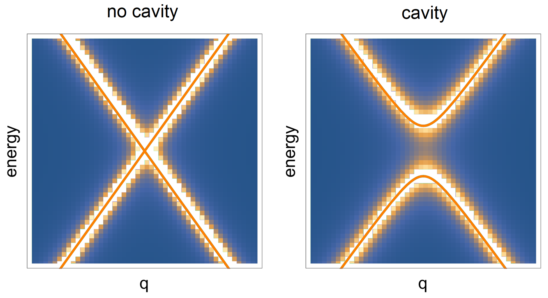
where are the Pauli matrices. The Hamiltonian gives a linear dispersion relation as shown in the left panel of Fig.S1. Time reversal symmetry breaking can be modelled by allowing for a new term in the Hamiltonian , which becomes
| (S2) |
Solving the eigenvalue equation for the above Hamiltonian, the dispersion relation under broken time reversal symmetry reads . The resulting band structure acquire a band gap at the Dirac point, as shown in the right panel of Fig.S1.
In Fig.S1 we show the band structure of graphene given by the model based on Eq.(S1) and the one obtained numerically by coupling graphene to the chiral cavity, as explained in the main text for TBG. The two results match very well and show that the chiral cavity opens a gap at the Dirac point as well, as a natural consequence of time reversal symmetry breaking.
SM2 The role of the cavity frequency
In order to complete our analysis, we now discuss briefly the role of the characteristic frequency of the chiral optical cavity . In the main text, we have fixed eV, which is a reasonable and experimentally realizable value. In Fig.S2, we study how the electronic spectrum is modified for larger values of such a frequency. Panels (a) and (b) of Fig.S2 have to be compared with panel (d) of Fig.2 in the main text, which shows the same results for smaller . We observe that increasing the cavity frequency the electronic bands becomes broader and the quasi-flat bands get closer to the other gapped bands at higher energy. Eventually, as a consequence of this strong broadening, the quasi-flat bands are not isolated anymore. This indicates that a large optical cavity frequency is detrimental in engineering isolated topological flat bands.

SM3 Efficiency of the cavity
In order to discuss the effect of the chiral cavity in more detail, we can define the “flattening-efficiency” as,
| (S3) |
where is the bandwidth parameter discussed in the main text. From this definition it can be found that takes values in the range from to . The minimum value means that the chiral cavity has no effect on the flatness of the isolated bands. On the contrary, the maximum value correspond to a perfect flattening of the band after having introduce the cavity, . More in general, a large value of implies that the bands are strongly flattened by the chiral cavity with respect to their structure at .
Fig.S3 shows the flattening parameter as a function of the twisting angle and the dimensionless coupling across the phase diagram, around the magic angle value . We observe that, except for small or near the magic angle, the chiral cavity can always greatly improve the flatness of band. The results in Fig.S3 are consistent with those reported in the main text in Fig.4.

SM4 Numerical methods and details of the setup
The Hamiltonian of monolayer graphene can be obtained by considering the hopping of electrons from one carbon atom to its three nearest neighboring atoms. The electronic band structure shows a characteristic linear dispersion relation around Fermi energy. The low energy Hamiltonian reads Catarina et al. (2019)
| (S4) |
where is the Fermi velocity which is around .
However, the situation in twisted bilayer graphene (TBG) is more complicated because the unit cell of the Moiré pattern is much larger than that of graphene. Hence, the Moiré Brillouin zone is quite small in reciprocal space and therefore one should consider many hopping channels between a group of Moiré Brillouin zones in the two layers. More details on this point can be found in Catarina et al. (2019). Below is the effective low energy Hamiltonian for TBG used in this manuscript:
| (S5) |
In this effective Hamiltonian, indicate the Hamiltonian of the top/bottom layer. Moreover, , , , where and are Moirè reciprocal vectors. The twisting angle is hidden in these vectors. The hopping matrix elements are given by,
| (S6) |
where and is the hopping parameter.
It should be noticed here that the Hamiltonian matrix of TBG shown in Eq.(S5) is not of dimension . Indeed, one should extend the matrix Eq.(S5) by taking into account more bases to obtain the flat band at the magic angle. For example, in the basis , indicates the top/bottom layer, while indicates the combination of two Moire reciprocal vectors, namely . According to this formula, the Hamiltonian matrix should be dimesional.
As outlined in the main text, in principle the self-energy is given by an infinite sum over the Matsubara frequencies as
| (S7) |
where is the Matsubara frequency and the coupling parameter between photon and electron. Nevertheless, from a computational perspective, the Matsubara frequency summation in Eq.(S7) is performed by introducing a finite UV cutoff
| (S8) |
The computations shown in the main text are for . To make sure that the sum converged for the value of the cutoff used in the main text, we have computed the same spectral function with different cutoffs as shown in Fig.S4. The results show only little difference upon changing the cutoff from to confirming that the numerical method is reliable.
Finally, let us emphasize that the propagator used in the main text is just the lowest order self-energy without any self consistent calculation. To obtain more accurate results, one should obtain the two solutions, and , consistently by iteration algorithm. However, the lowest order self energy is enough to grasp the main features.
