Bragg intersections
Abstract
We theoretically study nearly uniform electron models with weak crystalline potentials. In particular, we theorize the modulation of the plane-wave branches at linear regions where multiple Bragg planes intersect. Any such linear intersections involve three or more plane-wave branches diffracted by the periodic potential. Small inter-branch interactions can yield various crossing and anticrossing singularities with promised breakdown of the quadratic approximation, extending alongside the intersection lines. Most of the intersections run in low-symmetric paths in the Brillouin zone and therefore we cannot completely characterize their electronic states with standard band structure plotting methods. The present theory reveals a general mechanism in nearly uniform systems to induce approximately degenerate and linearly continuous Dirac and van-Hove singularities in three dimensions, which may host a variety of anomalous low-energy electronic properties. We apply the theory to a recently discovered high temperature superconductor H3S to interpret the enigmatic density-of-state peaking therein.
I Introduction
The crystal structure is the source of various low-energy electronic phenomena, including high-temperature superconductivity. One key effect of that is the formation of the one-particle band structure and resulting nontrivial distribution of the eigenstates in crystal wavenumber and energy space; enhanced density of states, nesting, band flattening, as well as topological structure in eigenfunctions. But relationship between the crystal and band structures is quite nontrivial and, for theory-driven materials design, heuristic approaches are usually utmost effective: Namely, build artificial crystals and execute first principles calculations for those. Useful theories on any such relationships, that may enable design strategies beyond heuristic, have long been desired.
In this study, we seek such a theory by focusing on a geometric aspect of electron as a plane wave under diffraction by periodic potentials. Understanding of the electronic band structure from the diffracted plane waves has been already well established in the Bloch theory [1], but, in order to find clues toward any missing theories, let us here briefly review the diffraction of the plane waves with elementary concepts. Due to the diffraction potential, the plane waves with (real) wave vector and are hybridized to form eigenstates, where and denote the reciprocal vector conforming to the system’s translational symmetry. When the diffraction is weak, such hybridization occurs only between energetically degenerate states. This mechanism is efficiently visualized by the repeated Brillouin zone scheme [2] [Fig. 1(a)]. In this view, the wavenumbers at which two diffracted branches meet span Bragg planes. The Bragg planes between the origin and adjacent reciprocal points defines the first Brillouin zone. At the Brillouin zone boundary, there always emerge linearly crossing or anticrossing band pairs. In the latter case, the band gradients have zero components normal to the zone boundary due to symmetry and continuity requirements of the bands. Such anomalies also occur near (not exactly at) the Bragg planes for farther reciprocal points, which may be located in the interior of the Brillouin zone.
The above is the well established description of the diffraction effect on the band structure. In this paper, we address what happens where two or more Bragg planes intersect, which is a problem that to our knowledge have eluded in-depth consideration up to the present. By definition, at such intersections three or more diffracted branches are degenerate and, with weak periodic perturbations, crossing and anticrossing band reconstruction should occur there. The interactions between more than two diffracted waves should be far more diverse than on the Bragg planes due to the increased degrees of freedom of relative geometry of the branches and inter-branch matrix elements. Thus the intersections of the Bragg planes are expected to induce various kinds of linearly extended crossing or anticrossing band critical points in the Brillouin zone. Notably, general properties that are only determined by the crystal geometry should be found in the limit of weak diffractions.
Motivated by the above expectations, in this paper we explore the electronic theory at the intersections of the Bragg planes. For cubic crystals, we derive the positions of the intersection lines, many of which are found to run along low-symmetry paths away from standard -point paths for the band structure calculations. Some typical interactions at the intersections are demonstrated. In particular, we indeed find an example where the Bragg intersections may be the origin of linearly extended saddle van Hove singularity [3] and peaked electronic density of states: cubic H3S [4], known as 200 K superconductor. The present theoretical considerations encourage studies on electronic states under weak periodic potentials with a renewed interest, as well as an overhaul of band structure analysis methods, both of which will be useful for theoretical materials design.
II Theory
Hereafter we consider the diffraction of the plane waves with the repeated zone scheme mentioned above. There, the branches of the diffracted waves are conveniently represented as the band replicas shifted by reciprocal vectors ; or as a shorthand notation each represents a diffracted planewave branch. Usually the Bragg planes are defined as the bisection of the line between the origin and a reciprocal point . For convenience we adopt a duplicate definition of the Bragg plane as a bisector of the line connecting two reciprocal points and , by
| (1) |
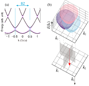
Let us substantiate the concept of intersection of Bragg planes. Since the Bragg planes are bisections between two reciprocal points, their linear intersection is equidistant from three or more reciprocal points. Take three reciprocal vectors , and and define the triangle formed by them as . The intersection line, termed , is normal to and passes through its circumcenter . Since the energy of branches are determined by the radius measured from the corresponding reciprocal points, three or more diffracted replica branches exactly cross on the intersection lines [Fig. 1 (b)].
Let us next examine the two-dimensional bandstructure on near the intersection with introduction of weak diffraction potential. The band structure is modeled by the Hamiltonian
| (5) |
with . This model can generate various structures; here we show some typical ones.
| Label | (Radius)2 | Center | Direction | Conventional path | Symmetry | BCC | FCC | ||
|---|---|---|---|---|---|---|---|---|---|
| l(1) | 1/2 | (1, 1, 0) | (1, 0, 0) | (1/2, 1/2, 1) | (0, 0, 1) | ✓ | C4v | ||
| l(2) | 2/3 | (1, 1, 0) | (1, 0, 1) | (-1/3, 1/3, 1/3) | (-1,1,1) | ✓ | C3v | ✓ | |
| l(3) | 3/4 | (1, 1, 1) | (1, 1, 0) | (1/2, 1/2, 1/2) | (1, -1,0) | ✓ | C2v | ||
| l(4) | 1 | (1, 1, 0) | (1, -1, 0) | (0,0,0) | (0,0,1) | ✓ | C4v | ✓ | |
| l(5) | 9/8 | (1, 1, 1) | (1, 1, -1) | (-1/4, -1/4, 0) | (1, -1, 0) | C1v | ✓ | ||
| l(6) | 5/4 | (1, 1, 1) | (1, 0, 2) | (1/2, 0, 0) | (-2, 1, 1) | C1 | |||
| l(7) | 25/18 | (1, 1, 0) | (1, 0, 2) | (-5/18, 5/18,-2/18) | (-2, 2, 1) | C1 | |||
| l(7’) | 25/18 | (1, 0, 2) | (-1, 0, 1) | (1/6, 0, 1/6) | (0, 1, 0) | C1 | |||
| l(8) | 3/2 | (1, 1, 2) | (1, 1, 0) | (1/2, 1/2, 0) | (1, -1, 0) | ✓ | C2v | ✓ | |
| l(8’) | 3/2 | (1, 1, 2) | (1, 0, 2) | (1/2, 1/2, 0) | (-2, 0, 1) | ✓ | C2v | ✓ | |
| l(9) | 25/16 | (1, 0, 2) | (-1, 0, 2) | (0, 0, 1/4) | (0, 1, 0) | C1v | |||
| l(10) | 45/28 | (1, 1, 1) | (0, -1, 2) | (5/14, -1/14, 3/14) | (-3, 2, 1) | C1 | |||
| l(11) | 18/11 | (1, 1, 2) | (0, -1, 1) | (5/11, 2/11, 2/11) | (-3,1,1) | C1 | ✓ | ||
| l(12) | 25/14 | (1, 1, 2) | (0, -1, 2) | (5/14,1/14, -4/14) | (-4, 2, 1) | C1 | |||
| l(13) | 9/5 | (1, 1, 2) | (1, -1, 2) | (-2/5, 0, 1/5) | (-2, 0, 1) | C1v | ✓ | ||
| l(14) | 2 | (1, 1, 2) | (1, 0, 1) | (0, 0, 0) | (-1, -1, 1) | ✓ | C3v | ✓ | |
| l(15) | 9/4 | (1, 1, 2) | (1, 1, 1) | (0, 0, 1/2) | (-1, 1, 0) | ✓ | C2v |
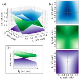
With weak nondiagonal components, three crossing bands evolves into partially anticrossing bands. As long as all the angles of are smaller than , their critical points are located near . A symmetry between any two reciprocal points forces a degeneracy of Dirac type, which is also near . This Dirac point can emerge either in upper or lower two bands of the three, depending on the signs of the nondiagonal components. In the vicinity of those anomalies, the quadratic expansion of is obviously broken down [Fig. 2].
The current analysis trivially applies to any planes normal to . With a reasonable smooth k-dependence of the nondiagonal components, the anomalies, Dirac or non-quadratic critical points, therefore extend continuously along , which is the key concept of the current theory.
The expected continuous anomalies generally have nonzero dispersions in that direction. If they exhibit extrema along that, nevertheless, they are almost always anomalous critical points where the rank of the inverse mass matrix is smaller than three [5]. We always expect such critical points near since all the noninteracting replica branches are trivially convex in the direction.
We also note about intersections of the intersection lines. Any intersection lines cross anywhere with others related by some symmetry (e.g., at the BZ surface). The replica branches involved in each intersection lines all interact at such crossing points, by which the continuous anomalies of the respective intersections are connected, smoothly unless additional degeneracies hold. As a result, looped anomalies running across the intersection lines emerge.
To sum up, any three replica plane waves are degenerate at the threefold Bragg intersections, at which they interact with each other to form continuous band anomalies running at its proximity. Remarkably, most of the intersections are not located along the high-symmetry lines. The automated band calculation procedure using the standardized -path definitions cannot reveal the whole shape of the continuous anomalies related to the intersections since the calculations run only along selected high symmetry lines. To capture the true figure of the anomalies, nonstandard band analysis methods are needed as we demonstrate below.
III Examples
To reveal the actual behavior of the intersections in crystals, we analyze the nearly uniform electron model [2]. The model is described by Hamiltonian with the plane-wave basis set as
| (11) |
where conforms to the corresponding translational symmetry. The crystalline potential, having the translational symmetry as well, is characterized by the Fourier components
| (12) |
In the uniform limit , the band structure corresponds to that of the free electron folded into the Brillouin zone (empty lattice model).
III.1 Cubic lattices
For example, we here derive the intersection lines in a simple cubic Bravais lattice. We performed an exhaustive search of triads of reciprocal lattice points that form triangles. The triads are listed in Table 1 with their circumcenter positions and directions of the intersection lines.
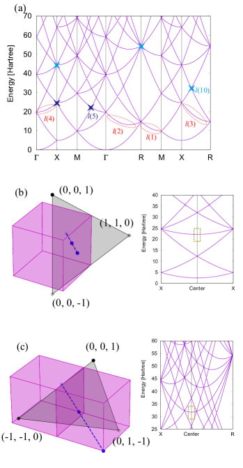
Seen by ascending order with respect to the squared radius, the first four lines – are along the special high symmetry paths in the Brillouin zones (see reviews, e.g., Ref. [6] for path labeling), which can be found by the standard band calculations. The first nontrivial intersection is , whose position is depicted in Fig. 3(b). We also indicate in Table if each intersection is on the standard k-point paths.
We plot the free dispersion folded in the Brillouin zone (empty lattice model) [Fig.3(a)]. The intersection appears there as threefold degenerate bands. Some intersections are on the standard k-point paths: we mark repersentatives of such lines – in the plot. On the other hand, other intersections are not running along the standard paths and we can see only their cuts as points, which we also mark for representative lines and . Calculations on non-standard paths are necessary for revealing the whole structure of the threefold degenerate bands, as shown in Fig. 3(b)(c).
The degeneracy of the threefold bands along the intersection is generally lifted by infinitesimal crystalline potential in diverse ways. We are not doing thorough examinations of that but instead seeing two representative cases, and .
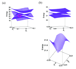
The intersection is joined by three branches originating from , , , which form isosceles triangle. An example set of interactions (see caption in Fig. 3) modifies the crossing branches to form several critical points. A Dirac point is then ensured somewhere near the intersection on the plane normal to , as demonstrated in Fig. 4(a). Since the same applies to any planes normal to the intersection, there forms a dispersive Dirac nodal line in the vicinity of as well as continuous lines with zero normal gradients.
The intersection is joined by branches , , forming a scalene triangle. This line runs straight across X and R points on different Brillouin zone replicas in a fractional direction [Fig. 3(c)]. Without obvious symmetry among the inter-branch interactions, we do not explore any general remarks on how the branches interact but just do show bands with several extrema and saddles in Fig. 4(b), which extend along .
The significance of these anomalies depends also on the band dispersion along the intersections, which should also be a common property determined by only the spatial symmetry. In the above case show smaller dispersions compared with [See Fig. 3]. In the next subsection, we see an example material where continuous saddles emerging from an intersection with small dispersion yield a sharp peak in the density of states.
III.2 Cubic H3S at high pressure
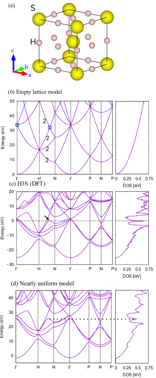
By applying extreme pressure on solid hydrogen sulfide, there forms a body-centered cubic (BCC) phase with unconventional composition H3S [Fig. 5(a)]. Superconductivity at 200 K has been discovered under pressures around 200 GPa [4, 8, 9]. First-principles calculation has revealed that an anomalously narrow peak of the density of states (DOS) is located at the Fermi level, which is thought to be responsible for the strong superconducting pairing interaction [8, 10, 11, 12, 13, 14, 15, 16, 17, 18, 19]. The origin of the peak has been, however, enigmatic. Obvious flat bands like those in the nearest-neighbor tight-binding model [20, 21, 22] have not been found in the first-principles band structures. The effective tight-binding models have been proposed [11, 23, 19, 24] using the Slater-Koster [25] and first-principles Wannierization methods [26, 27, 28], with which some features in the band structure are successfully reproduced. But why the peak emerges from the models were not thoroughly investigated. The author has attempted this in a preceding paper [24]. There he located saddle points extended in a loop form, termed saddle loop, and clarified that it is responsible for the DOS peak. However, to explain why the saddle loops emerge from the effective Wannier model, an intricate scenario based on farther neighbor hopping was necessary. In this section, we reexamine this issue with the knowledge of the intersections of Bragg planes.
We start from observing a remarkable resemblance of the first-principles band structure of H3S and empty lattice model one, shown in Fig.5(b)(c). The first-principles band structure was calculated using Quantum Espresso code package [29], with the detailed condition being the same as that in Ref. [24]. In addition to their apparent similarity, we find that the (near)-degenerate bands are assigned to the empty-lattice counterparts with perfect correspondence in the degrees of degeneracy [numbers in Fig. 5(b)]. This implies that the H3S band structure could be well understood as the empty-lattice model with weak perturbations. In particular, the states contributing to the DOS peak in panel (c) seems to have emerged from the intersection line , that remains both in the SC and BCC lattices [Table 1], and whose cross sections in the empty lattice limit are highlighted as points in panel (b).
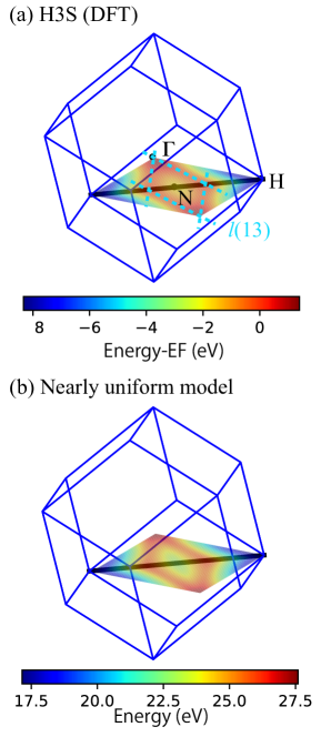
We further examine the detailed band structure of H3S. We show in Fig. 6(a) the Kohn-Sham eigenvalues of the 5th (in the ascending order) valence band that is responsible for the DOS peak. The eigenvalues are represented as a heat map on the plane , from which it is clear that the extremum indicated in Fig.5 (c) continuously extends inward the first Brillouin zone, with small band dispersion. Since this band has been found to be convex in the direction [24], this feature is classified as saddle loop. This saddle loop has been recently reproduced independently [30]. Note that the major portion of this looped structure has been first pointed out in a different look based on the conventional simple-cubic Brillouin zone [24]. The edges of the loops match the intersection lines , which further support the hypothesis that the extended saddle originates from the intersection lines.
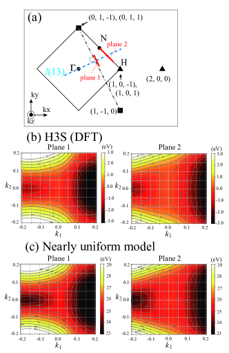
To the basic considerations in the previous section, electronic band dispersions around the extended singularities originating from the intersections should significantly depart from the quadratic forms. To confirm this we also show the band structures in two planar regions crossing [Fig. 7(b)]. The contour plots clearly show high-order angular structures beyond quadratic. The characterization of the singularities based on the effective masses [19] is hence incomplete for this system.
Finally, we attempt to reproduce the band features found above using the nearly uniform electron model [Eq. (11)] on the BCC lattice. Through an only preliminary search, we found a set of potential components that reproduced the crossing and anticrossing features with surprising accuracy as shown in Fig. 5(d). Subtle misordering of the degenerate bands was found at , though the electronic states around which is not responsible for the DOS peak [24]. We were also successful in reproducing the abovementioned planar dependences of the first-principles band by the model [Figs. 6(b) and 7(c)], as well as the peaked DOS [Fig. 5(d)]. To our close analysis the band features concerned are formed by six plane-wave branches per intersection as depicted in Fig. 7(a).
Thus, we have seen that the major features of the band contributing to the DOS peak is interpretable from the nearly uniform electron model perspective. However, there is still missing how to reconcile it with the molecular orbital perspective [31, 32, 33] that usually applies to molecular crystals. This point should be addressed in later studies. At this point, we stop by recalling a discussion by Kohn, on a Wannierization of nearly free-electron like systems [34]: Bloch-Wannier transformation to the plane-wave states yield function of form . The previously published Wannier functions in H3S show remarkable sign changes and long tails [19, 24], which may indicate significant planewave-like characters of the relevant electronic states.
IV Summary
In this paper, we have theorized effects of the intersections of the Bragg planes on the electronic single particle band structure. The translational symmetry determines the linearly extended regions in the k space in whose vicinity three or more plane-wave replica branches sensitively interact. Spatially extended higher order band anomalies are ensured to emerge around those regions, though their detailed features may depend on the Fourier components of the ionic potential. The present theory captures a mechanism of forming extended Dirac and van Hove singularities in three dimensional systems, which had long been hidden behind the difficulty of understanding the band structure, being a three dimensional hypersurface in four () dimensions.
The new theoretical view have helped an unprecedented complete characterization of the first-principles electronic band structure near the Fermi level in cubic H3S. The current analysis encourages further studies of possible anomalous low-energy phenomena from the non-quadratic band dispersion [5, 35] and complementary understanding of this system from nearly uniform electron perspective. Re-investigation on the electron-phonon perturbation theories with precise treatment of the revealed band features are also of interest [36, 37, 38, 39].
Acknowledgment
This work was supported by JSPS KAKENHI Grant Numbers 20K20895 and 23K03313 from Japan Society for the Promotion of Science (JSPS). The author thanks to Yu-ichiro Matsushita, Taichi Kosugi, Yusuke Nishiya and Hung Ba Tran for useful comments. Some of the calculations were performed at the Supercomputer Center in ISSP, the University of Tokyo.
References
- Bloch [1929] F. Bloch, Zeitschrift für Physik 52, 555 (1929).
- Ashcroft and Mermin [1976] N. Ashcroft and N. D. Mermin, Solid State Physics (Cangage and Learning, Inc., 1976).
- Van Hove [1953] L. Van Hove, Phys. Rev. 89, 1189 (1953).
- Drozdov et al. [2015] A. P. Drozdov, M. I. Eremets, I. A. Troyan, V. Ksenofontov, and S. I. Shylin, Nature 525, 73 (2015).
- Yuan et al. [2019] N. F. Q. Yuan, H. Isobe, and L. Fu, Nature Communications 10, 5769 (2019).
- Setyawan and Curtarolo [2010] W. Setyawan and S. Curtarolo, Computational Materials Science 49, 299 (2010).
- Momma and Izumi [2011] K. Momma and F. Izumi, Journal of Applied Crystallography 44, 1272 (2011).
- Duan et al. [2014] D. Duan, Y. Liu, F. Tian, D. Li, X. Huang, Z. Zhao, H. Yu, B. Liu, W. Tian, and T. Cui, Scientific Reports 4, 6968 (2014).
- Einaga et al. [2016] M. Einaga, M. Sakata, T. Ishikawa, K. Shimizu, M. I. Eremets, A. P. Drozdov, I. A. Troyan, N. Hirao, and Y. Ohishi, Nature Physics 12, 835 (2016).
- Errea et al. [2015] I. Errea, M. Calandra, C. J. Pickard, J. Nelson, R. J. Needs, Y. Li, H. Liu, Y. Zhang, Y. Ma, and F. Mauri, Phys. Rev. Lett. 114, 157004 (2015).
- Bernstein et al. [2015] N. Bernstein, C. S. Hellberg, M. D. Johannes, I. I. Mazin, and M. J. Mehl, Phys. Rev. B 91, 060511 (2015).
- Bianconi and Jarlborg [2015a] A. Bianconi and T. Jarlborg, EPL (Europhysics Letters) 112, 37001 (2015a).
- Bianconi and Jarlborg [2015b] A. Bianconi and T. Jarlborg, Novel Superconducting Materials 1, 37 (2015b).
- Jarlborg and Bianconi [2016] T. Jarlborg and A. Bianconi, Scientific Reports 6, 24816 (2016).
- Papaconstantopoulos et al. [2015] D. A. Papaconstantopoulos, B. M. Klein, M. J. Mehl, and W. E. Pickett, Phys. Rev. B 91, 184511 (2015).
- Akashi et al. [2015] R. Akashi, M. Kawamura, S. Tsuneyuki, Y. Nomura, and R. Arita, Phys. Rev. B 91, 224513 (2015).
- Flores-Livas et al. [2016] J. A. Flores-Livas, A. Sanna, and E. K. Gross, The European Physical Journal B 89, 63 (2016).
- Akashi et al. [2016] R. Akashi, W. Sano, R. Arita, and S. Tsuneyuki, Phys. Rev. Lett. 117, 075503 (2016).
- Quan and Pickett [2016] Y. Quan and W. E. Pickett, Phys. Rev. B 93, 104526 (2016).
- Jelitto [1969] R. J. Jelitto, Journal of Physics and Chemistry of Solids 30, 609 (1969).
- Souza and Marsiglio [2016] T. X. R. Souza and F. Marsiglio, Phys. Rev. B 94, 184509 (2016).
- Souza and Marsiglio [2017] T. X. R. Souza and F. Marsiglio, International Journal of Modern Physics B 31, 1745003 (2017), https://doi.org/10.1142/S0217979217450035 .
- Ortenzi et al. [2016] L. Ortenzi, E. Cappelluti, and L. Pietronero, Phys. Rev. B 94, 064507 (2016).
- Akashi [2020] R. Akashi, Phys. Rev. B 101, 075126 (2020).
- Slater and Koster [1954] J. C. Slater and G. F. Koster, Phys. Rev. 94, 1498 (1954).
- Marzari and Vanderbilt [1997] N. Marzari and D. Vanderbilt, Phys. Rev. B 56, 12847 (1997).
- Souza et al. [2001] I. Souza, N. Marzari, and D. Vanderbilt, Phys. Rev. B 65, 035109 (2001).
- Mostofi et al. [2014] A. A. Mostofi, J. R. Yates, G. Pizzi, Y.-S. Lee, I. Souza, D. Vanderbilt, and N. Marzari, Computer Physics Communications 185, 2309 (2014).
- Giannozzi et al. [2017] P. Giannozzi, O. Andreussi, T. Brumme, O. Bunau, M. B. Nardelli, M. Calandra, R. Car, C. Cavazzoni, D. Ceresoli, M. Cococcioni, N. Colonna, I. Carnimeo, A. D. Corso, S. de Gironcoli, P. Delugas, R. A. DiStasio, A. Ferretti, A. Floris, G. Fratesi, G. Fugallo, R. Gebauer, U. Gerstmann, F. Giustino, T. Gorni, J. Jia, M. Kawamura, H.-Y. Ko, A. Kokalj, E. Küçükbenli, M. Lazzeri, M. Marsili, N. Marzari, F. Mauri, N. L. Nguyen, H.-V. Nguyen, A. O. de-la Roza, L. Paulatto, S. Poncé, D. Rocca, R. Sabatini, B. Santra, M. Schlipf, A. P. Seitsonen, A. Smogunov, I. Timrov, T. Thonhauser, P. Umari, N. Vast, X. Wu, and S. Baroni, Journal of Physics: Condensed Matter 29, 465901 (2017).
- [30] M. Goesten and S. R. Thomsen, private communication.
- Heil and Boeri [2015] C. Heil and L. Boeri, Phys. Rev. B 92, 060508 (2015).
- Flores-Livas et al. [2020] J. A. Flores-Livas, L. Boeri, A. Sanna, G. Profeta, R. Arita, and M. Eremets, Physics Reports 856, 1 (2020).
- Belli et al. [2021] F. Belli, T. Novoa, J. Contreras-García, and I. Errea, Nature Communications 12, 5381 (2021).
- Kohn [1959] W. Kohn, Phys. Rev. 115, 809 (1959).
- Markiewicz [1997] R. Markiewicz, Journal of Physics and Chemistry of Solids 58, 1179 (1997).
- Durajski et al. [2015] A. P. Durajski, R. Szczes̀niak, and Y. Li, Physica C: Superconductivity and its Applications 515, 1 (2015).
- Sano et al. [2016] W. Sano, T. Koretsune, T. Tadano, R. Akashi, and R. Arita, Phys. Rev. B 93, 094525 (2016).
- Capitani et al. [2017] F. Capitani, B. Langerome, J. B. Brubach, P. Roy, A. Drozdov, M. I. Eremets, E. J. Nicol, J. P. Carbotte, and T. Timusk, Nature Physics 13, 859 (2017).
- Ghosh et al. [2019] S. S. Ghosh, Y. Quan, and W. E. Pickett, Phys. Rev. B 100, 094521 (2019).