Theory of the Simultaneous Transient Dispersive Readout of Multiple Spin Qubits
Abstract
We propose a paradigm of multiplexed dispersive qubit measurement performed while the qubits dephase. A Laplace transformation of the time-dependent cavity response allows to separate contributions from multiple qubits coupled to the same resonator mode, thus allowing for simultaneous single-shot read out. With realistic parameters for silicon spin qubits we find a competitive readout fidelity, while the measurement time compares favourably to conventional dispersive readout. We extend the multiplexed readout method to quantum non-demolition measurements using auxiliary qubits.
Introduction –– Fast high-fidelity readout is a key requirement to any qubit implementation [1], in particular in view of quantum error correction [2, 3, 4]. The use of dispersively coupled microwave resonators [5] was pioneered by superconductiong qubits [6, 7, 8]. Dispersive readout makes use of a qubit-state dependent shift in the resonance frequency of the resonator. Similar techniques are now in reach for spin qubits in semiconductor quantum dots (QDs) [9, 10] which have demonstrated strong spin-photon coupling [11, 12, 13] mediated by artificial spin-orbit coupling in a double QD (DQD) [14, 15]. The dispersive readout of a single spin qubit was experimentally demonstrated [11, 16] and theoretically optimized [17, 18].
To scale up quantum processors and to facilitate fault-tolerant quantum computation, it is desirable to speed up qubit measurements by reading out multiple qubits simultaneously. With several qubits dispersively coupled to the same resonator, however, it is challenging to distinguish the contributions of the individual qubits [19, 20, 21], although parametric or dissipative dynamics allow a certain enhancement [22, 23, 24]. Readout with specialized electronics for each qubit [25] introduces bulky components and thus limits scalability. In the context of superconducting qubits it is now common to use one readout resonator with individual frequency per qubit coupled to a shared microwave feedline [26, 27, 28, 29, 30]. Utilizing gate-dispersive sensing [31, 32, 33, 34, 35, 36] similar efforts are ongoing for spin qubits [37, 38, 39]. In this Letter we propose a cavity-based multi-qubit readout in the dispersive regime relying on transient qubit-cavity interaction terms, illustrated in Fig. 1(a,b). The signals stemming from different qubits coupled to the same resonator can be distinguished by a Laplace transform, allowing to read out multiple qubits simultaneously. We analyze the readout fidelity and discuss optimal operating regimes.
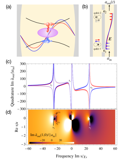
Model –– We consider multiple DQDs in an inhomogeneous magnetic field, where the th DQD is occupied by a single electron and is described by , with and , where () is the vector of Pauli operators for the position (spin). Then, is the energy detuning between the left and right QD, is the spin-conserving tunneling matrix element, the Zeeman splitting, and the difference in transverse magnetic field between the QDs in energy units [15, 17]. We assume that all DQDs couple to a single cavity mode, , via the electric dipole interaction , where annihilates a photon, is the resonator frequency, and is the charge-photon coupling strength [40, 41]. The leakage rates at the resonator ports are defined as and . A probe field with frequency and amplitude is injected into port 1 of the resonator.
Transforming the system into the eigenbases of [17] allows to define a spin qubit with Pauli operators in the orbital ground state of each DQD while the synthetic spin-orbit coupling gives rise to the indirect spin-photon coupling [15, 17]. To describe cavity-based readout of the spin qubits we perform a rotating wave approximation and apply a Schrieffer–Wolff transformation [42, 43] to model the dispersive regime where all electronic transitions are off-resonant from the probe field [5]. In the spin-like subspace we find [17]. Here, [] is the detuning of the resonator frequency [spin qubit splitting ] from the probe field, is the dispersive shift due to the spin with . The equations of motion for and are finally obtained by including the incoherent interactions derived from input-output theory [17]
| (1) | |||||
| (2) |
with and , and where is the dephasing rate of qubit and . The output field at port 2 of the cavity found as [44, 45, 17]
| (3) |
The last terms in Eqs. (1) and Eq. (3) are usually neglected in the treatment of dispersive readout since they vanish in the stationary state where the qubit is dephased and in a typical measurement setup they are removed by frequency filters to reduce noise. However, the dependence of the output field on before the steady state is reached implements a measurement of the -basis of qubit if the detection is sufficiently broadband. This readout must be considered destructive as the qubit dephases in the process. Alternatively, a quantum non-demolition (QND) measurement in the -basis can be performed if an ancilla is entangled with the qubit and then coupled to the resonator, while the qubit is quickly detuned to a protected idling spot [46, 47].
Contributions from multiple qubits can be separated in frequency [48] and thus observed simultaneously by detuning the qubit splittings from each other. This detuning will also suppress coherent oscillations between different qubits mediated by the resonator [5], justifying their negligence in Eqs. (1) and (2)
Proposed readout procedure –– Assuming that the interaction between DQD and resonator is switched on at time the Laplace transform [49] of the output field,
| (4) | |||||
| (5) |
can be found from Eqs. (1) and (2), with the field as a function of the complex frequency
| (6) |
where . For the qubit , exhibits a singularity at . The slope of the singularity depends on the initial state . For the basis states of the -basis this is and .
We assume that the quadrature of the transmitted output field is measured [17] and derive its Laplace transform with the aid of the identity [49]. An example for with two qubits is shown in Fig. 1(c). It is clearly possible to distinguish the initial state of each qubit by choosing a proper complex readout frequency and evaluating . All plots are drawn for realistic values of , , , , , , , and [11]. With this choice the qubit-qubit interaction mediated by the resonator can thus be safely neglected, since [19]. The input power is chosen such that the steady state cavity population is no more than 5% of the critical photon number for the dispersive approximation [50, 17].
To separate the singularities of the individual qubits along the imaginary axis of the complex frequency space the qubit frequency can be tuned by means of and to set and for each qubit. The electrostatic detuning of the DQDs has a weaker effect since [15, 46, 17]. By tuning the qubit away from its sweet spot , however, the dephasing can be enhanced [46]. This offers a possibility to separate the contributions along the real axis.
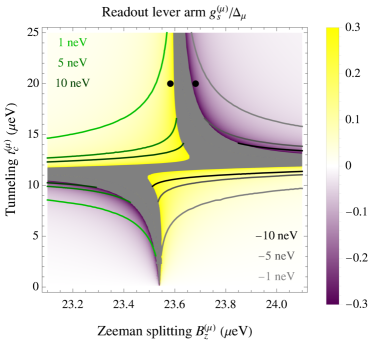
Tuning and to separate the qubits will also alter , which appears as a prefactor in Eq. (5) and which we denote as the readout lever arm. In Fig. 2 we plot and contours of constant , showing that it is indeed possible to choose different with comparable . Note, however, that is required to keep the spin-photon interaction off-resonant.
In an experiment, can be obtained by performing a series of short heterodyne measurements of with a duration of , for a total readout time . The numerical Laplace transform of the discrete time data can be implemented by the -transformation and yields a continuous function in the complex frequency space [51]. We assume that the choice of the readout frequency in the complex plane is limited only by the accuracy of the frequency measurement and thus .
Readout fidelity –– Equation (4) yields only the expectation value of the output field. Assuming that the fluctuations are Gaussian we also derive the variance
| (7) | |||||
| (8) | |||||
of the measured quadrature in the complex frequency space. Here, we have used that a quadrature of the output field can be be measured with accuracy in a given time , where with the number of thermal noise photons , and the number of noise photons added by the detector [17]. We assume that the input field is limited by vacuum fluctuations () and that the detector is quantum limited () [52] to estimate the optimal fidelity. The term emerges when an ancilla is entangled with the qubit to allow a QND measurement, with a fidelity of the entangling two-qubit gate.
First, we estimate the readout fidelity for a single qubit, for simplicity. We define a threshold to discriminate , where is the initial qubit state. The initial qubit state is identified as [] upon observation of with [] and as [] otherwise. The probability to incorrectly find is given by and the probability to incorrectly find is , defined as
| (9) |
The upper sign should be used if , the lower sign otherwise. The choice minimizes [53].
Equation (9) is valid for a direct -measurement of the qubit. If an entangling gate with fidelity is used to measure the qubit via an ancilla, then the readout fidelity , necessitating optimized gates [54, 55]. We account for this by introducing and , where the first (second) term corresponds to readout (two-qubit gate) error. We finally define the readout infidelity [56, 57].
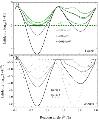
In Fig. 3(a) the single-qubit readout infidelity is plotted as a function of . The optimal readout fidelity is achieved if is imaginary, due to the shape of the singularity. The orientation of with respect to gives rise to an anisotropy in complex frequency space. For the readout becomes impossible if faces towards since in that case , where no distinction between the qubits states is possible [see Fig. 2(c)]. Generally, a smaller grants lower because it reduces the frequency uncertainty and also increases . Furthermore, should be as small as agreeable with the dispersive approximation to boost .
The fidelity is straightforward to generalize to multiple qubits when taking into account that is conditional on the state of the other qubits. To estimate the single-qubit readout fidelity of qubit in a simultaneous measurement of two qubits, Fig. 3(b), we average the threshold over all states of the other qubit. In our example the two qubits are symmetrically detuned from the cavity frequency and thus their singularities are mirrored copies of each other.
Remarkably, there are choices of where our readout scheme fails. For example, if it is impossible to discern the basis states of qubit 2 with a single unconditional threshold . To identify choices of where this problem does not occur we demand where is a sign dependent on the DQD parameters and is averaged over all two-qubit states. Using also the analogous condition for qubit 1 we find that both qubits can be read out if for
| (10) |
This provides a rule how far the readout frequency of qubit must be from the singularity of the other qubit and from . Here, if . Together with the tuneability of and in a given device this complex frequency qubit spacing determines how many qubits can be read out simultaneously.
So far, the relaxation of the qubits was neglected. To include relaxation, the equations
| (11) |
for the qubit populations are taken into account along with Eqs. (1) and (2). Here, and are the intrinsic and Purcell qubit relaxation rates (assuming ) [17]. The solution of this extended set of equations has the same form as Eqs. (4), (5), with an altered -term in , Eq. (5), capturing the effect of the relaxation. This term does not depend on the qubit states and thus reduces the readout contrast. We consider the ratio of qubit state-dependent and qubit state-independent terms, and conclude that the effect of relaxation on can be neglected if for all
| (12) |
For a constant qubit population on the timescale of the readout, and . With increasing relaxation, the phase shift between the two signals of the output field is reduced and approaches a saturation value. If (12) is not fulfilled, the effect of the relaxation is too strong and the qubit state-dependent components cannot be identified from the decomposition of the output field. Another limitation for the relaxation rate is , otherwise only limited information is gained. For realistic silicon spin-qubit parameters (12) is satisfied and relaxation is expected to be insignificant [11].
Finally, we compare our proposed transient multi-qubit readout to the usual dispersive readout of multiple qubits. Modelling two qubits coupled to one resonator [19, 20] under the above assumptions, we find that the transient dispersive readout is approximately one order of magnitude faster if a comparable fidelity for the multi-qubit state is required. Compared to the dispersive readout of a single qubit per resonator we still find a speed-up by a factor of between 1.5 and 2. Note however, that the transient dispersive readout is either destructive and requires re-initialization or an overhead in qubits and a two-qubit gate which limits the readout fidelity.
Conclusions – The transient dispersive readout proposed in this letter can be a potent tool for the fast, multiplexed, and/or selective readout of resonator-coupled qubits. This holds the promise of greatly advancing the scalability of solid-state qubits since it speeds up the readout of entire registers, leaving more time for gate operation and opening the pathway for quantum error correction. After demonstrating the basic concept of the readout scheme, we expect that the evaluation protocol can be optimized further for future applications, relying on a fit to the heterodyne signal, rather than the evaluation at certain points in the complex frequency domain.
Acknowledgements.
We thank Jonas Mielke, Joris Kattemölle, Adam R. Mills, Xuanzi Zhang, and Jason R. Petta for helpful discussions. This work has been supported by the Army Research Office (ARO) grant number W911NF-15-1-0149.References
- DiVincenzo [2000] D. P. DiVincenzo, The physical implementation of quantum computation, Fortschritte der Physik 48, 771–783 (2000).
- Terhal [2015] B. M. Terhal, Quantum error correction for quantum memories, Rev. Mod. Phys. 87, 307 (2015).
- Chen et al. [2022] E. H. Chen, T. J. Yoder, Y. Kim, N. Sundaresan, S. Srinivasan, M. Li, A. D. Córcoles, A. W. Cross, and M. Takita, Calibrated decoders for experimental quantum error correction, Phys. Rev. Lett. 128, 110504 (2022).
- Sundaresan et al. [2022] N. Sundaresan, T. J. Yoder, S. Kim, M. Li, E. H. Chen, G. Harper, T. Thorbeck, A. W. Cross, A. D. Córcoles, and M. Takita, Matching and maximum likelihood decoding of a multi-round subsystem quantum error correction experiment (2022), arXiv:2203.07205.
- Blais et al. [2004] A. Blais, R.-S. Huang, A. Wallraff, S. M. Girvin, and R. J. Schoelkopf, Cavity quantum electrodynamics for superconducting electrical circuits: An architecture for quantum computation, Phys. Rev. A 69, 062320 (2004).
- Wallraff et al. [2005] A. Wallraff, D. I. Schuster, A. Blais, L. Frunzio, J. Majer, M. H. Devoret, S. M. Girvin, and R. J. Schoelkopf, Approaching unit visibility for control of a superconducting qubit with dispersive readout, Phys. Rev. Lett. 95, 060501 (2005).
- Schuster et al. [2005] D. I. Schuster, A. Wallraff, A. Blais, L. Frunzio, R.-S. Huang, J. Majer, S. M. Girvin, and R. J. Schoelkopf, ac stark shift and dephasing of a superconducting qubit strongly coupled to a cavity field, Phys. Rev. Lett. 94, 123602 (2005).
- Koch et al. [2007] J. Koch, T. M. Yu, J. Gambetta, A. A. Houck, D. I. Schuster, J. Majer, A. Blais, M. H. Devoret, S. M. Girvin, and R. J. Schoelkopf, Charge-insensitive qubit design derived from the cooper pair box, Phys. Rev. A 76, 042319 (2007).
- Burkard et al. [2021] G. Burkard, T. D. Ladd, A. Pan, J. M. Nichol, and J. R. Petta, Semiconductor spin qubits (2021), arXiv: 2112.08863.
- Hanson et al. [2007] R. Hanson, L. P. Kouwenhoven, J. R. Petta, S. Tarucha, and L. M. K. Vandersypen, Spins in few-electron quantum dots, Rev. Mod. Phys. 79, 1217 (2007).
- Mi et al. [2018] X. Mi, M. Benito, S. Putz, D. M. Zajac, J. M. Taylor., G. Burkard, and J. R. Petta, A coherent spin–photon interface in silicon, Nature 555, 599 (2018).
- Samkharadze et al. [2018] N. Samkharadze, G. Zheng, N. Kalhor, D. Brousse, A. Sammak, U. C. Mendes, A. Blais, G. Scappucci, and L. M. K. Vandersypen, Strong spin-photon coupling in silicon, Science 359, 1123 (2018).
- Landig et al. [2018] A. J. Landig, J. V. Koski, P. Scarlino, U. C. Mendes, A. Blais, C. Reichl, W. Wegscheider, A. Wallraff, K. Ensslin, and T. Ihn, Coherent spin–photon coupling using a resonant exchange qubit, Nature 560, 179 (2018).
- Hu et al. [2012] X. Hu, Y.-x. Liu, and F. Nori, Strong coupling of a spin qubit to a superconducting stripline cavity, Phys. Rev. B 86, 035314 (2012).
- Benito et al. [2017] M. Benito, X. Mi, J. M. Taylor, J. R. Petta, and G. Burkard, Input-output theory for spin-photon coupling in si double quantum dots, Phys. Rev. B 96, 235434 (2017).
- Borjans et al. [2021] F. Borjans, X. Mi, and J. Petta, Spin digitizer for high-fidelity readout of a cavity-coupled silicon triple quantum dot, Phys. Rev. Applied 15, 044052 (2021).
- D’Anjou and Burkard [2019] B. D’Anjou and G. Burkard, Optimal dispersive readout of a spin qubit with a microwave resonator, Phys. Rev. B 100, 245427 (2019).
- Ruskov and Tahan [2019] R. Ruskov and C. Tahan, Quantum-limited measurement of spin qubits via curvature couplings to a cavity, Phys. Rev. B 99, 245306 (2019).
- Majer et al. [2007] J. Majer, J. M. Chow, J. M. Gambetta, J. Koch, B. R. Johnson, J. A. Schreier, L. Frunzio, D. I. Schuster, A. A. Houck, A. Wallraff, A. Blais, M. H. Devoret, S. M. Girvin, and R. J. Schoelkopf, Coupling superconducting qubits via a cavity bus, Nature 449, 443 (2007).
- Filipp et al. [2009] S. Filipp, P. Maurer, P. J. Leek, M. Baur, R. Bianchetti, J. M. Fink, M. Göppl, L. Steffen, J. M. Gambetta, A. Blais, and A. Wallraff, Two-qubit state tomography using a joint dispersive readout, Phys. Rev. Lett. 102, 200402 (2009).
- DiCarlo et al. [2010] L. DiCarlo, M. D. Reed, L. Sun, B. R. Johnson, J. M. Chow, J. M. Gambetta, L. Frunzio, S. M. Girvin, M. H. Devoret, and R. J. Schoelkopf, Preparation and measurement of three-qubit entanglement in a superconducting circuit, Nature 467, 574–578 (2010).
- Xiao et al. [2022] Z. Xiao, E. Doucet, T. Noh, L. Ranzani, R. Simmonds, L. Govia, and A. Kamal, Perturbative diagonalization for time-dependent strong interactions, Phys. Rev. Applied 18, 024009 (2022).
- Noh et al. [2021] T. Noh, Z. Xiao, K. Cicak, X. Y. Jin, E. Doucet, J. Teufel, J. Aumentado, L. C. G. Govia, L. Ranzani, A. Kamal, , and R. W. Simmonds, Strong parametric dispersive shifts in a statically decoupled multi-qubit cavity qed system (2021), arXiv:2103.09277.
- D’Anjou and Coish [2017] B. D’Anjou and W. A. Coish, Enhancing qubit readout through dissipative sub-poissonian dynamics, Phys. Rev. A 96, 052321 (2017).
- Neeley et al. [2010] M. Neeley, R. C. Bialczak, M. Lenander, E. Lucero, M. Mariantoni, A. D. O’Connell, D. Sank, H. Wang, M. Weides, J. Wenner, Y. Yin, T. Yamamoto, A. N. Cleland, and J. M. Martinis, Generation of three-qubit entangled states using superconducting phase qubits, Nature 467, 570–573 (2010).
- Jerger et al. [2011] M. Jerger, S. Poletto, P. Macha, U. Hübner, A. Lukashenko, E. Il’ichev, and A. V. Ustinov, Readout of a qubit array via a single transmission line, Europhysics Letters 96, 40012 (2011).
- Jerger et al. [2012] M. Jerger, S. Poletto, P. Macha, U. Hübner, E. Il’ichev, and A. V. Ustinov, Frequency division multiplexing readout and simultaneous manipulation of an array of flux qubits, Applied Physics Letters 101, 042604 (2012), https://doi.org/10.1063/1.4739454 .
- Chen et al. [2012] Y. Chen, D. Sank, P. O’Malley, T. White, R. Barends, B. Chiaro, J. Kelly, E. Lucero, M. Mariantoni, A. Megrant, C. Neill, A. Vainsencher, J. Wenner, Y. Yin, A. N. Cleland, and J. M. Martinis, Multiplexed dispersive readout of superconducting phase qubits, Applied Physics Letters 101, 182601 (2012), https://doi.org/10.1063/1.4764940 .
- Jeffrey et al. [2014] E. Jeffrey, D. Sank, J. Y. Mutus, T. C. White, J. Kelly, R. Barends, Y. Chen, Z. Chen, B. Chiaro, A. Dunsworth, A. Megrant, P. J. J. O’Malley, C. Neill, P. Roushan, A. Vainsencher, J. Wenner, A. N. Cleland, and J. M. Martinis, Fast accurate state measurement with superconducting qubits, Phys. Rev. Lett. 112, 190504 (2014).
- Schmitt et al. [2014] V. Schmitt, X. Zhou, K. Juliusson, B. Royer, A. Blais, P. Bertet, D. Vion, and D. Esteve, Multiplexed readout of transmon qubits with josephson bifurcation amplifiers, Phys. Rev. A 90, 062333 (2014).
- Colless et al. [2013] J. I. Colless, A. C. Mahoney, J. M. Hornibrook, A. C. Doherty, H. Lu, A. C. Gossard, and D. J. Reilly, Dispersive readout of a few-electron double quantum dot with fast rf gate sensors, Phys. Rev. Lett. 110, 046805 (2013).
- Pakkiam et al. [2018] P. Pakkiam, A. V. Timofeev, M. G. House, M. R. Hogg, T. Kobayashi, M. Koch, S. Rogge, and M. Y. Simmons, Single-shot single-gate rf spin readout in silicon, Phys. Rev. X 8, 041032 (2018).
- West et al. [2019] A. West, B. Hensen, A. Jouan, T. Tanttu, C.-H. Yang, A. Rossi, M. F. Gonzalez-Zalba, F. Hudson, A. Morello, D. J. Reilly, and A. S. Dzurak, Gate-based single-shot readout of spins in silicon, Nature Nanotechnology 14, 437–441 (2019).
- Urdampilleta et al. [2019] M. Urdampilleta, D. J. Niegemann, E. Chanrion, B. Jadot, C. Spence, P.-A. Mortemousque, C. Bäuerle, L. Hutin, B. Bertrand, S. Barraud, R. Maurand, M. Sanquer, X. Jehl, S. De Franceschi, M. Vinet, and T. Meunier, Gate-based high fidelity spin readout in a cmos device, Nature Nanotechnology 14, 737–741 (2019).
- Zheng et al. [2019] G. Zheng, N. Samkharadze, M. L. Noordam, N. Kalhor, D. Brousse, A. Sammak, G. Scappucci, and L. M. K. Vandersypen, Rapid gate-based spin read-out in silicon using an on-chip resonator, Nature Nanotechnology 14, 742–746 (2019).
- Crippa et al. [2019] A. Crippa, R. Ezzouch, A. Aprá, A. Amisse, R. Laviéville, L. Hutin, B. Bertrand, M. Vinet, M. Urdampilleta, T. Meunier, M. Sanquer, X. Jehl, R. Maurand, and S. De Franceschi, Gate-reflectometry dispersive readout and coherent control of a spin qubit in silicon, Nature Communications 10, 2776 (2019).
- Hornibrook et al. [2014] J. M. Hornibrook, J. I. Colless, A. C. Mahoney, X. G. Croot, S. Blanvillain, H. Lu, A. C. Gossard, and D. J. Reilly, Frequency multiplexing for readout of spin qubits, Applied Physics Letters 104, 103108 (2014), https://doi.org/10.1063/1.4868107 .
- Fedele et al. [2021] F. Fedele, A. Chatterjee, S. Fallahi, G. C. Gardner, M. J. Manfra, and F. Kuemmeth, Simultaneous operations in a two-dimensional array of singlet-triplet qubits, PRX Quantum 2, 040306 (2021).
- Ruffino et al. [2022] A. Ruffino, T.-Y. Yang, J. Michniewicz, Y. Peng, E. Charbon, and M. F. Gonzalez-Zalba, A cryo-cmos chip that integrates silicon quantum dots and multiplexed dispersive readout electronics, Nature Electronics 5, 53–59 (2022).
- Cohen-Tannoudji et al. [1989] C. Cohen-Tannoudji, J. Dupont-Roc, and G. Grynberg, Photons and Atoms. Introduction to Quantum Electrodynamics (John Wiley & Sons, New York, 1989).
- Scully and Zubairy [1997] M. Scully and M. Zubairy, Quantum Optics (Cambridge University Press, Cambridge, 1997).
- Schrieffer and Wolff [1966] J. R. Schrieffer and P. A. Wolff, Relation between the anderson and kondo hamiltonians, Phys. Rev. 149, 491 (1966).
- Bravyi et al. [2011] S. Bravyi, D. P. DiVincenzo, and D. Loss, Schrieffer–wolff transformation for quantum many-body systems, Ann. Phy. 326, 2793 (2011).
- Collett and Gardiner [1984] M. J. Collett and C. W. Gardiner, Squeezing of intracavity and traveling-wave light fields produced in parametric amplification, Phys. Rev. A 30, 1386 (1984).
- Gardiner and Collett [1985] C. W. Gardiner and M. J. Collett, Input and output in damped quantum systems: Quantum stochastic differential equations and the master equation, Phys. Rev. A 31, 3761 (1985).
- Benito et al. [2019] M. Benito, X. Croot, C. Adelsberger, S. Putz, X. Mi, J. R. Petta, and G. Burkard, Electric-field control and noise protection of the flopping-mode spin qubit, Phys. Rev. B 100, 125430 (2019).
- Fehse et al. [2022] F. Fehse, M. P.-L. M. David, and W. A. Coish, Generalized fast quasi-adiabatic population transfer for improved qubit readout, shuttling, and noise mitigation (2022), arXiv:2203.07517.
- Smith [1997] S. W. Smith, The Scientist and Engineer’s Guide to Digital Signal Processing (California Technical Publishing, San Diego, 1997).
- Doetsch [1974] G. Doetsch, Introduction to the theory and application of the Laplace transformation (Springer, Berlin, 1974).
- Boissonneault et al. [2010] M. Boissonneault, J. M. Gambetta, and A. Blais, Improved superconducting qubit readout by qubit-induced nonlinearities, Phys. Rev. Lett. 105, 100504 (2010).
- Palani [2022] S. Palani, The -transform analysis of discrete time signals and systems, in: Signals and systems (Springer, Cham., 2022) p. 921–1055.
- Clerk et al. [2010] A. A. Clerk, M. H. Devoret, S. M. Girvin, F. Marquardt, and R. J. Schoelkopf, Introduction to quantum noise, measurement, and amplification, Rev. Mod. Phys. 82, 1155 (2010).
- Elzerman et al. [2004] J. Elzerman, R. Hanson, L. W. van Beveren, B. Witkamp, L. Vandersypen, and L. Kouwenhoven, Single-shot read-out of an individual electron spin in a quantum dot, Nature 430, 431 (2004).
- Calderon-Vargas and Kestner [2017] F. A. Calderon-Vargas and J. P. Kestner, Dynamically correcting a gate for any systematic logical error, Phys. Rev. Lett. 118, 150502 (2017).
- Kanaar et al. [2022] D. W. Kanaar, U. Güngördü, and J. P. Kestner, Two-qubit controlled-z gates robust against charge noise in silicon while compensating for crosstalk using neural network, Phys. Rev. B 105, 245308 (2022).
- Meunier et al. [2006] T. Meunier, I. T. Vink, L. H. Willems van Beveren, F. H. L. Koppens, H. P. Tranitz, W. Wegscheider, L. P. Kouwenhoven, and L. M. K. Vandersypen, Nondestructive measurement of electron spins in a quantum dot, Phys. Rev. B 74, 195303 (2006).
- Nakajima et al. [2019] T. Nakajima, A. Noiri, J. Yoneda, M. R. Delbecq, P. Stano, T. Otsuka, K. Takeda, S. Amaha, G. Allison, K. Kawasaki, A. Ludwig, A. D. Wieck, D. Loss, and S. Tarucha, Quantum non-demolition measurement of an electron spin qubit, Nature Nanotechnology 14, 555–560 (2019).