Templated self-assembly of gold nanoparticles in smectic liquid crystals confined at 3D printed curved surfaces111Mackenzie O’Keefe and Jane Bernadette Denise M. Garcia contributed equally to this work.
Abstract
The fabrication of assembled structures of topological defects in liquid crystals (LCs) has attracted much attention during the last decade, stemming from the potential application of these defects in modern technologies. A range of techniques can be employed to create large areas of engineered defects in LCs, including mechanical shearing, chemical surface treatment, external fields, or geometric confinement. The technology of 3D printing has recently emerged as a powerful method to fabricate novel patterning topographies inaccessible by other microfabrication techniques, especially confining geometries with curved topographies. In this work, we show the advantages of using 3D-printed curved surfaces and controlled anchoring properties to confine LCs and engineer new structures of topological defects, whose structure we elucidate by comparison with a novel application of Landau-de Gennes free energy minimization to the smectic A-nematic phase transition. We also demonstrate the ability of these defects to act as a scaffold for assembling gold (Au) nanoparticles (NPs) into reconfigurable 3D structures. We discuss the characteristics of this templated self-assembly (TSA) approach and explain the relationship between NP concentrations and defect structures with insights gained from numerical modeling. This work paves the way for a versatile platform of LC defect-templated assembly of a range of functional nanomaterials useful in the field of energy technology.
keywords:
Smectic Liquid Crystals, Nanoparticles, Topological Defects, Curvature, Templated Self-assembly1 Introduction
The field of nanotechnology has been rapidly growing in the last decade. It has attracted enormous attention, particularly after the discovery of new nanomaterials and the development of diverse ways to manipulate them 1. The interest also stems from the potential of nanomaterials in producing new applications useful in a wide range of emerging fields, such as energy technology 2, bioengineering 3, sensing 4, 5, 6, and optics 7, 8, 9. For this reason, the scientific community has strived to develop new techniques to fabricate and manipulate nanocomposites. One class of these techniques is the top-down approach, which exploits the patterning of bulk materials to organize nanosized structures 10. Examples include the techniques of photolithography 11, soft lithography 12, scanning lithography 13, nanocontact printing 14, laser machining 15, and deposition 16. Another set of approaches are described as bottom-up methods, in which hierarchical nanostructures are assembled by building upon single atoms and molecules 17, 18. When these two kinds of methods are combined, they give rise to an innovative approach for nanofabrication, known as the templated-self-assembly (TSA) technique 19, where the top-down helps the bottom-up to create specific structures 20.
Liquid crystals (LCs) are complex fluids that have long been of interest because of their reconfigurable properties and their fast response to external stimuli. These materials have also attracted significant attention because of their topological defects that are easy to engineer and capable of guiding the assembly of different classes of functional nanomaterials 21, 22, 23, 24, 25, 26, 27, 28, 29. The use of LCs and their topological defects as a template for bottom-up designs has also opened new avenues for the development of new materials of both fundamental and technological interest. For example, they have been used as effective platforms for fabricating microlens arrays 30, 31, templates for soft lithography 32, and matrices for nanoparticle (NP) assembly 33, 34.
In this work, we propose a new mechanism of TSA, for which we combine bottom-up self-assembly with top-down patterned templates to create reconfigurable structures of LC defects capable of manipulating and organizing nanomaterials. In particular, we use the smectic LC phase, a class of soft materials characterized by a lamellar structure consisting of rod-shaped molecules arranged in parallel layers. Different classes of smectics are distinguished by the orientation of these molecules relative to the layer normal direction. In this study, we focus on the smectic A (SmA) phase that is characterized by a perpendicular orientation of molecules within the layers and often exhibits distinctive defect structures called focal conic domains (FCDs). In an FCD, the smectic layers wrap around two defect curves, an ellipse and a hyperbola each passing through a focus of the other, that contain singularities of layer curvature. Close-packed arrays of FCDs self-assemble when a SmA LC is confined with hybrid anchoring conditions, in which a perpendicular orientation is imposed at one interface through homeotropic anchoring while tangential orientations are imposed at the opposite interface through degenerate planar anchoring 28, 32. Surface topography strongly influences the placement of FCDs 35, 36, 37. When one of the confining interfaces has a curved geometry, the FCDs assemble into 3D hierarchical structures that can be manipulated by changing the surface geometry’s curvature, periodicity, and/or anchoring conditions 38, 39, 40.
Curvature is a fundamental concept useful in many fields, such as chemistry, condensed matter, and soft matter physics. This is because it introduces specific limitations that can impact the assembly of molecules by restricting the interaction patterns between them. Additionally, curvature can influence the self-assembly behavior of different types of nanomaterials by affecting their packing geometry and stability. Other examples include the impact of curvature on lipid bilayer kinetics 41, the phase behavior of 2D nanosystems 42, the properties of self-assembled monolayers 43, the dynamics of Brownian colloids 44, the interaction of anisotropic particles at fluid interfaces 45, and the organization of topological defects in LCs, both passive 46 and active 47. This is also true for biological systems such as red blood cells, for which curvature plays a critical role in the rapid gas exchange between hemoglobin and the surrounding medium to enable flexible migration into various vessels 48. The concept of curvature is also essential for understanding the behavior of materials with layered structures. A good example is the case of block copolymers, usually used in patterning applications or the engineering of nanostructures 49, 50. These systems show different curved geometries depending on the volume fraction of each block 51. SmA LCs offer another important example, as their bulk elasticity causes their layers to curve in precisely predictable ways, which can be selected through appropriate boundary conditions 52.
The control of curvature fields along with anchoring conditions could lead to powerful mechanisms to engineer director fields in LCs and assemble their defects. With the recent developments of microfabrication techniques and the emergence of the 3D nanoprinting technology, it is now possible to create curved geometries with complex shapes that were not achievable with traditional microfabrication methods 53. This opens the doors for new ways to confine LCs and harness the effects of curvature on the behavior of soft materials with lamellar order. In this study, we extend this approach to controllably create defects in LCs by confining a SmA film under hybrid anchoring at a 3D-printed surface with double undulations (i.e. height oscillations in the and directions). We thus use curvature fields to engineer the assembly of FCDs. We then demonstrate how these defect structures can be utilized as a scaffold to manipulate the assembly of gold (Au) NPs. We also discuss the features of this approach by analyzing the effect of Au NP concentration on the properties of the smectic film and the organization of defects.
2 Results and discussion
2.1 Confinement of the LC mixture at 3D printed curved surfaces
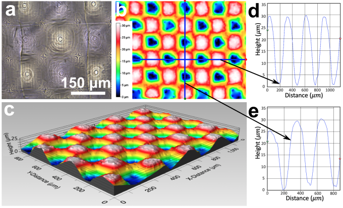
We confine a 4-pentyl-4-cyanobiphenyl (5CB)/ 4’-octyl-4-cyanobiphenyl (8CB) mixture at a ratio of 20/80 by weight percent (wt.), between a PDMS film that presents undulations in both and directions and a coverslip treated with polyvinyl alcohol (PVA). Figure 1 shows the optical image and the 3D profile of the PDMS film used to confine the mixture. The PDMS film was replicated from a 3D printed master mold that has undulations with peak-to-peak amplitudes of =252m and a wavelength of =3002m. The anchoring of the 5CB/8CB mixture is perpendicular at the PDMS surface and degenerate planar (tangential) at the coverslip, resulting in a hybrid alignment of the LC film. This alignment is confirmed by analyzing the texture and the defect structure of the mixture in the flat region in the same sample, where the LC film is uniform in both the N and smectic phases.
The 5CB/8CB system presents an isotropic phase at temperatures above C, a nematic (N) phase between and C, a smectic A (SmA) phase between and C, and a crystal phase below . Figure 2 shows optical images of the mixture near the N-SmA phase transition.
We used a mixture of 5CB and 8CB instead of pure 8CB because the latter presents a strong viscosity at room temperature, which could be a disadvantage with Au NPs. We found that adding a small amount of 5CB to the 8CB preserves the N and SmA mesophases, but modifies their phase transition temperatures, leading to a N phase at room temperature and a SmA phase at lower ones 54. We also noticed that the phase diagram of this system is very sensitive to the addition of 5CB. We tested different ratios and found the optimal concentration to be 20/80 wt., because higher 5CB concentrations suppress the SmA phase.
2.2 Characterization of the defect structure in the LC
We begin our characterization by analyzing the texture of the LC mixture near the N-SmA phase transition and comparing the patterns of LC defects at flat and double-undulated surfaces. The goal of this analysis is to understand the effect of curvature on the structure and assembly of topological defects in the N and SmA phases. When cooling the mixture from the isotropic to the N phase, we observe the appearance of disclinations lines that tend to shrink over time if the LC is maintained in its N phase. The energetic cost of these defect lines gives them an effective line tension 55, so the LC tends to shrink and eliminate them over time in order to minimize its free energy. However, this is not the case in the double undulated confinement. The defects could remain for a significant amount of time, suggesting that curvature is responsible for creating and stabilizing defects in N LCs.
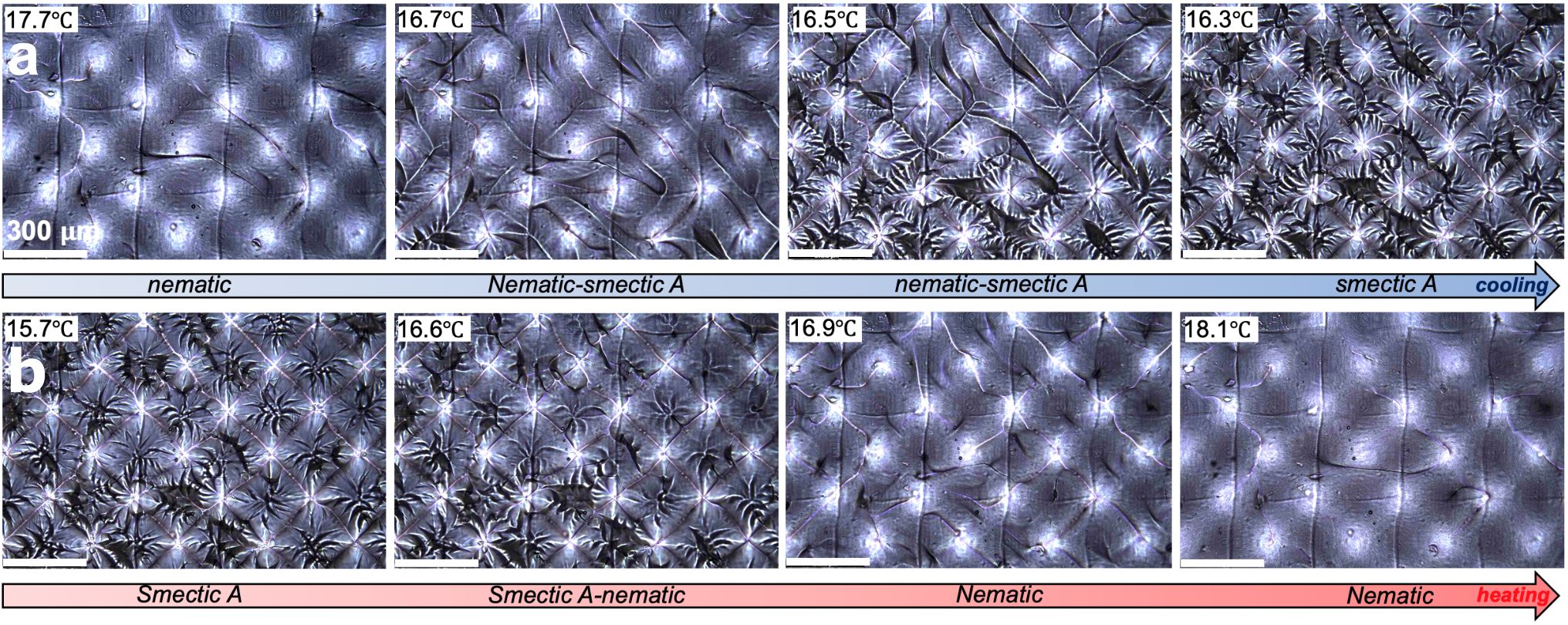
As the system is cooled toward the SmA phase, more disclinations appear at precise locations forming periodic patterns. Additionally, FCDs of different sizes emerge, forming hierarchical assemblies of larger and smaller defects around these disclinations. This process is reversible: disclinations in the N phase re-emerge at approximately the same locations after the system is heated and cooled through many cycles, as shown in Figure 2, exhibiting a form of geometric memory across the phase transition 56.
To better understand the formation of defects in the SmA phase and the role of the 3D printed surface, we characterized the structure of the defects as a function of the confining surface profile. Figure 3-a shows a typical optical image of the SmA confined at a double-undulated surface. From above, each FCD appears as an ellipse of high eccentricity, distinguishing these defects as elliptic-hyperbolic FCDs as opposed to the zero-eccentricity toric FCDs 57. Figure 3-b is the corresponding 3D reconstruction of the smectic texture obtained by scanning the sample along the -axis. These measurements indicate that the disclinations form a crosshatch grid of lines that appear to intersect near the coverslip, above the crests in the double-undulated surface. We are unable to determine the -separation of the defects, which means we cannot confirm if they are really intersecting or not. The FCDs assemble in groups resembling petals of a flower, centered at these disclination intersection sites. These results confirm the correlation between the morphology of the confining surface and the assembly of defects.
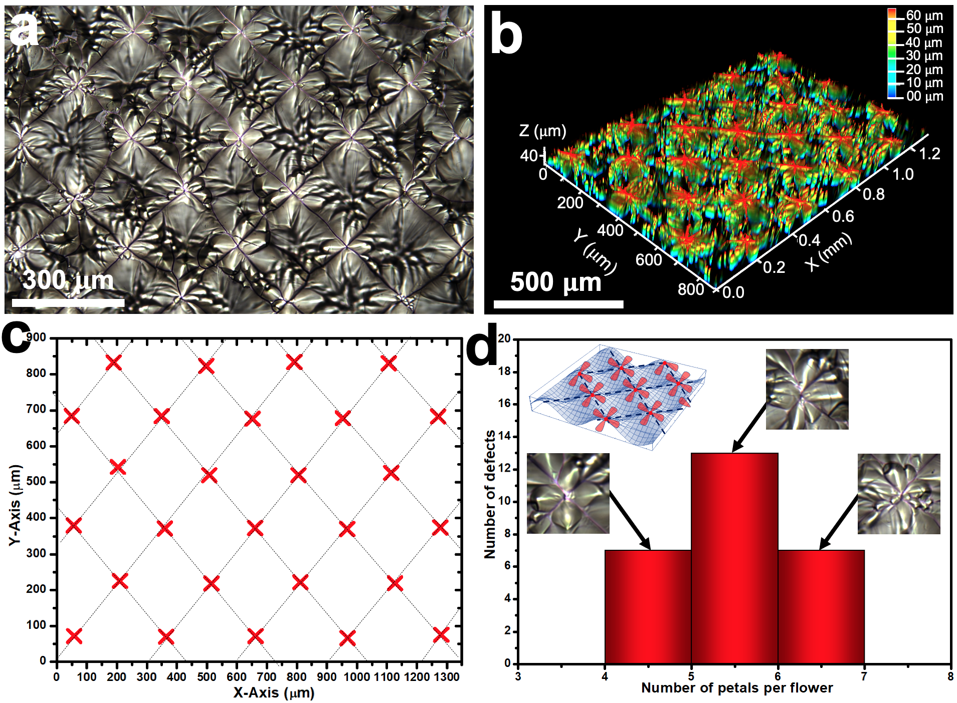
Additionally, we measured the number of petals present in the flower patterns and found that they all have between 4 and 6 petals, as shown in the histogram of Figure 3-d. However, the majority of the flowers present 5 petals. We believe that the variability in petal numbers is linked to the thickness of the smectic film between the crest of the double undulation and the coverslip’s surface, as FCDs’ size and number are sensitive to this parameter. Since the thickness of our samples varies slightly, which is challenging to regulate experimentally, the number of petals may differ from one region to another, as seen in Figure 3-a, from the bottom right to the top left. These results suggest that further control over FCD assembly structures may be obtainable by systematically varying parameters that we do not investigate here, including sample thickness and the amplitude and wavelength of the double undulations.
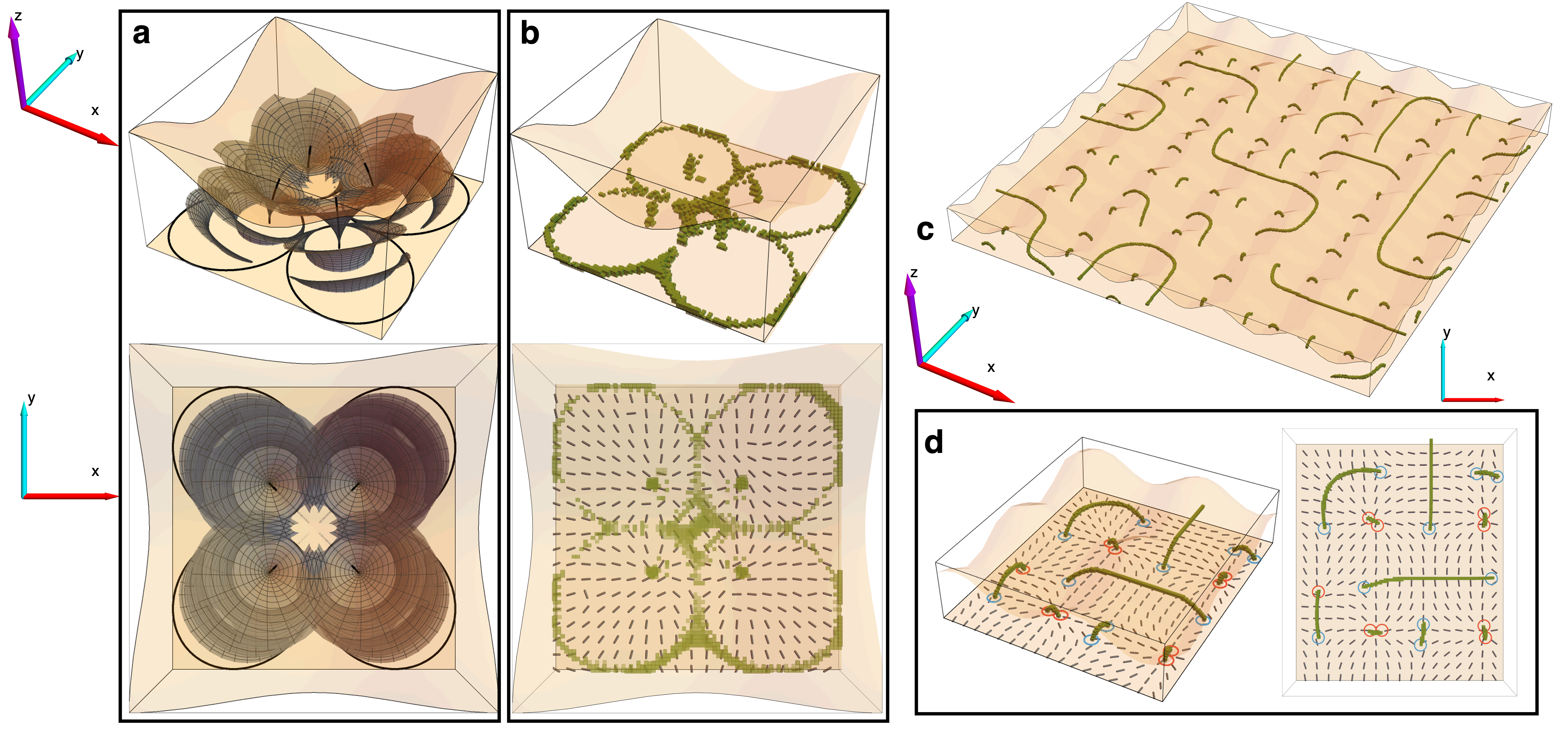
In order to better understand the LC defect configurations in the double-undulated confinement, and their reversible transformations at the N-SmA phase transition, we turn to numerical modeling. We perform a multi-step application of Landau-de Gennes (LdG) free energy minimization, accounting for the FCD arrangement in the SmA phase and the changing elasticity in the N close to . Figure 4-a shows the assumed arrangement of four elliptic-hyperbolic FCDs in each unit cell of the double-undulation, which we take as part of our model’s initial condition, choosing the most symmetrical FCD petal arrangement for simplicity. With the N director field within the FCDs known analytically 57, we first relax the director field only outside of the FCDs, and with bend elastic constant larger than the splay elastic constant, , to approximate the smectic configuration.
Starting from this FCD director configuration, we perform a second relaxation at over the entire domain to produce a modeled N configuration just above . Finally, a third relaxation at evolves the system into a metastable state deep inside the N phase. We find a large number of possible metastable disclination arrangements, with the defect lines’ endpoints lying on the flat (degenerate planar anchoring) surface. An example of such a metastable array is shown in Figures 4-c and d. This highly multistable scenario is in stark contrast with the disclination configuration arising under single-undulated confinement, as investigated experimentally in 40 and numerically in the Supporting Information (Figure S1), where the N LC exhibits a unique stable state with parallel, straight disclinations.
Furthermore, the curvature of the double undulated surface geometry determines the local structure of nearby defects: Disclination line endpoints where the N director has winding occur opposite the undulation crests, where the LC thickness is minimum, while those with winding lie opposite the saddle points (median thickness) of the double undulated surface. This indicates a relationship between surface defect “charge” at one interface and the Gaussian curvature of the nearby opposite surface, extending a connection between surface curvature and defect charge known previously from in-surface 58, 59 and bulk 60 behaviors.
Additionally, we observed the formation of point-like defects at the interstices of the ellipses of the FCDs. Defects with winding number were observed in the N state at the locations of the interstitial centers of converging FCD flower groups in the smectic initial condition, while defects with charge were observed at some of the sites of contact between FCDs belonging to different groups. These point-like defects appear as split-core short disclination lines 61 and are similar to those seen in previous simulations of toric FCD packings at the SmA-to-N phase transition 56. In the present context, it is interesting to note that the relationship between winding number and Gaussian curvature at the opposite surface follows the same trend for point-like defects as for the ends of extended disclination lines: positive charges appear opposite domes where the Gaussian curvature is positive, and negative charges appear opposite saddle points where the Gaussian curvature is negative. The presence of point defects was confirmed experimentally in our system, as shown in Figure-S2. The density of point defects is lower in experiment than in the numerical results, which may indicate that a more detailed model of the SmA-to-N phase transition will be required for quantitative comparison.
2.3 Directed assembly of Au NPs via engineered defects in the smectic LC
It is known that topological defects in LCs present strong trapping sites for nanomaterials 21, 22, 29, 33, 34. In this section, we explore the possibility of using defects assembled at curved geometries as a scaffold to organize NPs into reconfigurable ordered structures. We used Au NPs of nominal diameter , stabilized with citrate ligands and dispersed in the LC mixture at different concentrations. The presence of ligands at the NP surfaces helps them to disperse uniformly in the LC and prevents them from forming large aggregates. The ligands also promote degenerate planar anchoring of the LC molecules at the surfaces of the NPs. In this section, we focus on the SmA phase because of its highly organized defects. Our motivation is to investigate whether NPs could conform to the structure of LC defects.
We examined various concentrations of Au NPs, ranging from 0.01 wt. to 0.2 wt.. We first establish the behavior of our NPs in uniformly confined SmA films with hybrid alignment, where both interfaces are planar. The goal was to verify if NPs used in this study could interact with self-assembled FCDs, as previously demonstrated with other types of NPs 28, 62. Our findings show that the NPs are attracted to the FCDs and arranged in patterns that resemble the FCDs’ structure. This was confirmed by observing the sample near the N-SmA phase transition (Figure S3). These results demonstrate the potential of smectic defects in attracting the NPs and manipulating their organization.
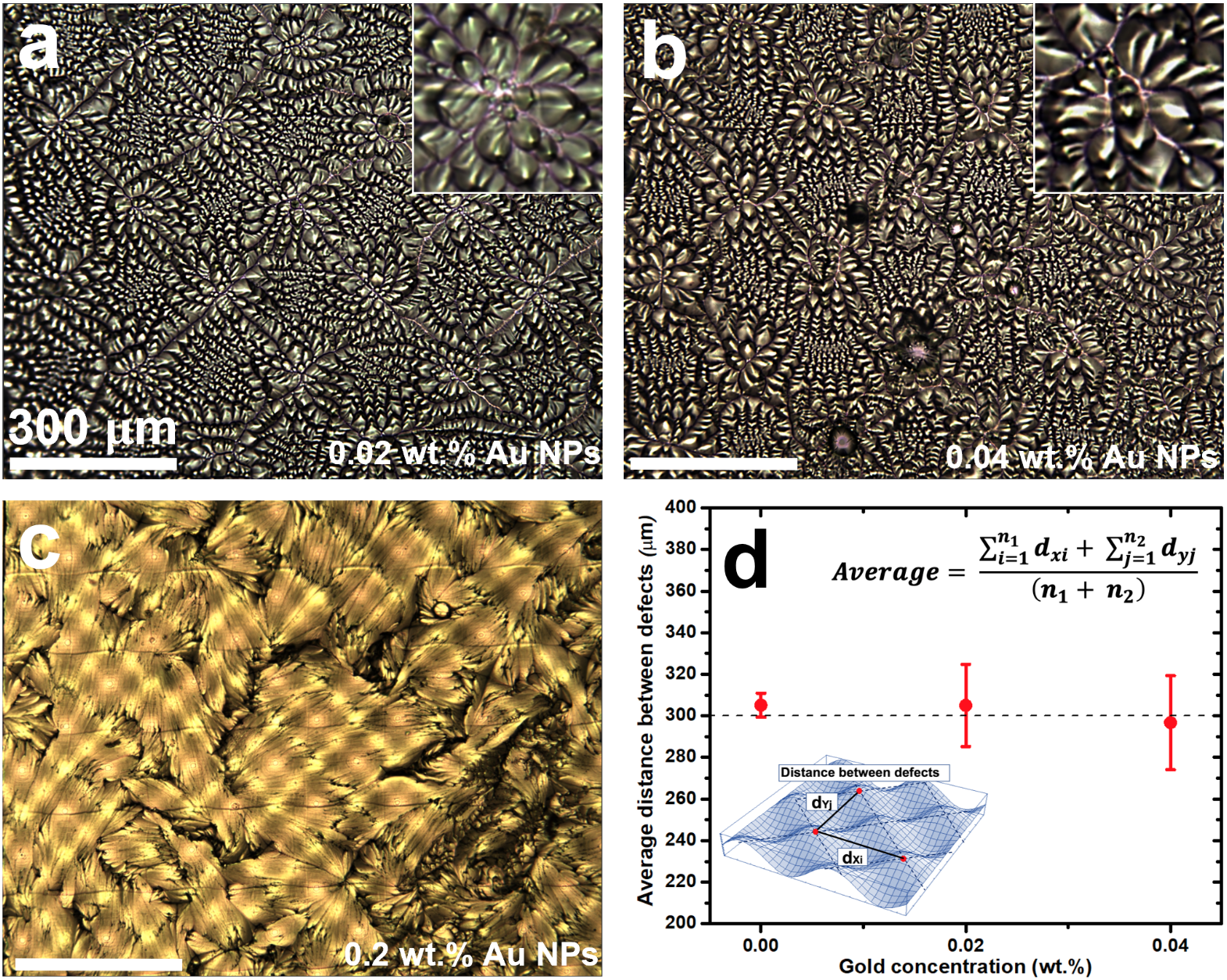
Figure 5 shows optical images of the samples prepared at different NP concentrations: 0.02 wt., 0.04 wt., and 0.2 wt.. Our results indicate that the presence of a low concentration of NPs doesn’t affect the structure of disclinations and FCDs in the smectic film, as shown in Figure 5-a. For Au NP concentration of 0.02 wt., the average distance between the defect lines, obtained by averaging the distances and between the defect intersections in both and directions (see inset of Figure 5-d), is 30520 m, compared to 3056 m for samples without NPs. This confirms that FCDs and disclinations created via curvature can serve as a template to guide the assembly of nanomaterials since they are strong trapping sites for NPs, as confirmed with flat samples. When the concentration of NPs is increased to 0.04 wt., these defects continue to form ordered structures but with some deformations in their arrangements, as shown in Figure 5-b. The flower patterns of FCDs that form around the disclinations become less defined with a larger number of petals. The average distance between the disclination intersection points decreases, and its standard deviation increases ( 29623 m). This result suggests that at certain concentrations, the NPs can distort the regular defect structures of the smectic obtained without or with low NP concentrations (see Figure 5-d).
When the concentration of NPs is higher than 0.2 wt., the texture of the smectic changes drastically, as shown in Figure 5-c. The FCDs and disclinations disappear, and the effect of surface curvature apparently vanishes. The smectic no longer presents a hybrid-aligned texture, suggesting that the anchoring conditions for the LC have changed at the boundaries. This could be induced by the accumulation of a large number of NPs at the surface of PDMS and coverslip due to the strong elastic forces of the LC expelling the NPs from the bulk. The presence of NPs at the boundaries could change the orientation of smectic layers at the double undulated surface to satisfy the surface anchoring of the NPs, which is degenerate planar, rather than the homeotropic anchoring of the PDMS. This result is similar to previous work with planar anchoring fluorosilane functionalized silica (F-SiO2) NPs dispersed in semi-fluorinated smectic LC 23. In that case, the NPs migrate to the boundaries and form monolayers capable of changing the alignment of smectic molecules. We believe that a similar mechanism is responsible for the change in smectic alignment in our system at high NP concentration. These results show that the TSA approach we propose in this study to organize NPs into reconfigurable 3D structures is inverted at high NP concentration: Rather than SmA LC defects directing the assembly of NPs, sufficiently concentrated NPs drastically alter the assembly of the SmA LC layers.
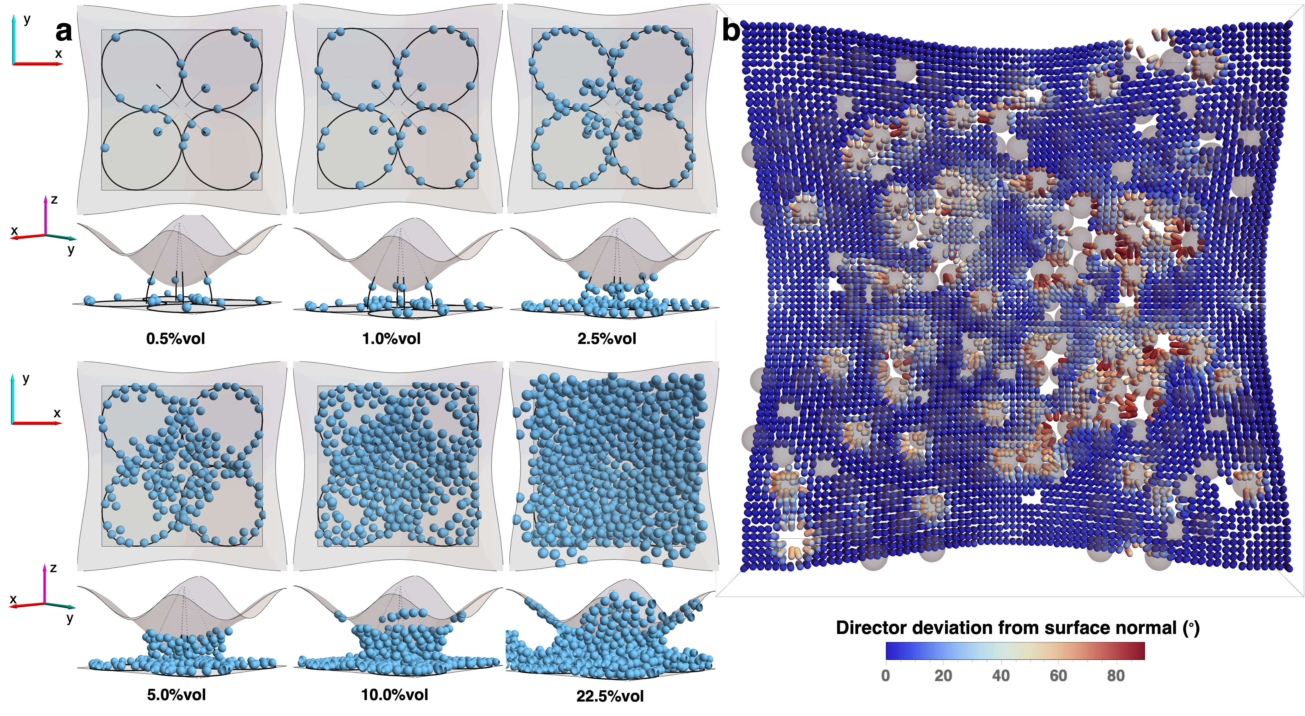
To gain insight into the concentration dependence of NP assembly in the SmA LC, we again employ LdG numerical free energy relaxation with adaptations to approximate a SmA configuration. NPs are introduced sequentially as small, spherical inclusions in the smectic-like LC configuration, with each NP’s location chosen to minimize the LC free energy, with all previously inserted NPs held fixed. When planar anchoring is imposed on the NP surfaces, we observe a sequence of NP assembly behavior: the NPs first decorate the elliptical defect lines of the FCDs, then decorate the hyperbolic defect lines, then pack near the flat surface, and next pack near the undulated surface, before finally filling the remainder of the LC bulk. This sequence of assembly is illustrated in Figures 6-a. We also numerically investigate the effect of anchoring imposed on the surface of the NPs in the Supporting Information (Figure S4), where we find that the ordered assembly of NPs is similarly observed in the case of homeotropic anchoring and no anchoring is imposed on the NP surface.
We can understand this assembly sequence based on the elastic energy cost of NPs, whose degenerate planar surface anchoring promotes bend distortions in the LC director field. As defects lines are regions of high free energy density, the LC free energy favors replacing portions of defect lines with NPs or colloidal particles, essentially reducing the energetic cost of these distortion sources by overlapping them 63. Similar reasoning explains the subsequent assembly of NPs at the boundaries, as the total boundary area (including NP surfaces) is thereby reduced, representing a benefit both in surface energies and bulk elastic distortions 64, 65.
Examining the effect of NP concentration on the director field, we performed an additional LdG free energy minimization over the LC bulk, with NP locations held fixed at different volume fractions in the assembly sequence of Figure 6-a. At low NP concentration, the LC director near the double undulated surface primarily follows that surface’s homeotropic anchoring condition. With increasing NP concentration, however, more sites near the double undulated surface are filled with NPs, resulting in an effective change in surface anchoring to the planar anchoring of the NP surfaces. This is further illustrated in Figure 6-b, where regions fully covered in NPs correspond to having deviation of the director from the surface normal of the undulated surface, i.e., the effective anchoring in these regions is planar. In contrast, regions of the undulated surface with smaller NP coverage correspond to regions with a small deviation of the director from the surface normal. These results support our hypothesis that high NP concentrations cause the hybrid-aligned FCD texture to be replaced with approximately vertical layers having horizontal normal direction, similar to the bookshelf arrangement of layers observed previously with F-SiO2 NPs in semi-fluorinated SmA LC 23.
3 Conclusion
In this work, we demonstrated the benefits of using 3D printing to create curved confining geometries for a SmA LC mixture in order to control its defects and manipulate NP assembly. We demonstrate how this technique offers design flexibility and scalability, enabling the development of LC films with tailored properties. We also explain how 3D printing provides a powerful tool for engineering defects in smectic LCs. Additionally, we establish how these defects could be used as a template to assemble Au NPs and discuss the features of this approach.
This technique of TSA could be adapted to various classes of functional nanomaterials useful in many technologies. For instance, it can be employed to enhance the performance of solar cells by incorporating quantum dots 66 or nanowires 67 into self-assembled FCDs. This may improve light absorption and charge transport within solar cells, leading to enhanced energy conversion efficiency. Another example is the fabrication of high-performance light-emitting devices 68. By integrating luminescent nanomaterials into smectics, FCDs can be engineered to create ordered emission patterns. This control over defect structures could enable the production of devices with enhanced light extraction efficiency, color purity, and improved viewing angles.
Additionally, defect assemblies in LCs offer opportunities for biosensing applications 69. By functionalizing the surfaces of nanomaterials with biomolecules or antibodies, FCDs can be used to capture and detect specific analytes or biological targets. The binding of these targets to the nanomaterials induces changes in the defect structures, which can be optically detected, enabling sensitive and label-free biosensing platforms. In each of these applications, the ability to control and manipulate LC defects provides a platform for the precise assembly and organization of nanomaterials, resulting in improved device performance, enhanced functionalities, and tailored properties.
4 Experimental Section
4.1 3D printed double undulated surfaces
The double undulated geometries used to confine the LC mixture are produced using the raster-scanning direct laser writing (rDLW) system built on a standard resonant-scanning two-photon microscope 53. This technique can print objects with minimum feature sizes of about 411m in the , , and directions, respectively. The 3D printed surfaces have undulations in both and directions with a peak-to-peak amplitude of =252m and a wavelength of =3002m. The double-undulated surfaces are initially printed with an IP-Dip photoresist (from Nanoscribe, GmbH) and are then transferred into a film of cross-linked polydimethylsiloxane (PDMS from Sigma-Aldrich). The PDMS film is obtained by mixing the elastomer and the curing agent at a ratio of 9 parts to 1 (9:1). The mixture is then set under vacuum until almost all the bubbles disappear from the solution. Thereafter, we place the solution into the oven for about an hour at 80 C until the PDMS becomes solid.
4.2 LC cell preparation
The LC mixture studied in this work is obtained by mixing 80 wt. of 4’-octyl-4-cyanobiphenyl (8CB, purchased from Kingston Chemicals Limited that displays a SmA phase at room temperature) with 20 wt. of 4-pentyl-4-cyanobiphenyl (5CB, purchased from Kingston Chemicals Limited that displays a N phase at room temperature). This LC mixture displays both N and SmA phases with a N-isotropic transition temperature at 39.30.2C and a SmA-N transition temperature at 16.40.4C. This mixture is helpful for the preparation of samples at room temperature, with and without NPs, because the N is less viscous than the SmA. The 8CB/5CB mixture is then confined between the PDMS film with the double-undulations and a coverslip treated with polyvinyl alcohol (PVA from Sigma-Aldrich). The thickness between the peaks of the undulations and the flat coverslip is estimated to be around 52m. The anchoring of the LC mixture is perpendicular in contact with the PDMS and planar at the PVA-treated coverslip. These anchoring conditions induce a ”hybrid texture” in the LC film responsible for the formation of defects in the N and SmA phases.
4.3 Dispersion of gold (Au) nanoparticles (NPs) in the LC
Spherical Au NPs of diameter 20m stabilized with citrate ligands in an aqueous solution (purchased from NNCrystal) are dried under a slow airflow to eliminate water. The dry NPs are then dispersed in an ethanol solution and added to the 5CB/8CB mixture. The solvent was then evaporated under a slow airflow at 60∘C overnight. Finally, the samples were vacuum-dried at the same temperature for one hour to eliminate any residual solvent. The samples were used immediately after the dispersion of NPs to avoid the formation of big aggregates.
4.4 Characterization
To characterize the 3D shape of the PDMS films with undulations and measure their peak-to-peak amplitude and wavelength, we used the Zeta-20 benchtop optical profiler. The LC mixture is studied under an upright optical polarizing microscope (Leica DM6 M) in transmission mode equipped with a temperature controller (Instec TS102-mK2000A) that has a precision 0.1 °C. This microscope is capable of collecting and comparing data in different modes simultaneously (bright field, polarized, and dark field). It is also equipped with an automated XYZ stage useful for 3D imaging and measurements. All images were recorded with a high-resolution digital camera (Leica DMC 5400).
5 Theory and Numerical Methods
5.1 Multi-step Landau-de Gennes free energy minimization
The Landau-de Gennes (LdG) free energy utilizes a second-order traceless and symmetric tensorial order parameter, , which contains information regarding the director and the N degree of order, 55, 57. The element of the Q-tensor is given by, in the uniaxial limit, . In the absence of an external field, the LdG free energy has three components: phase free energy, distortion free energy, and surface free energy,
| (1) |
In (1), the bulk free energy density components are
| (2) |
and
| (3) |
In the uniaxial limit, the distortion free energy can be written in terms of the Frank elastic constants:
| (4) |
where , and are the splay, twist and bend parameters, respectively. In terms of the elastic parameters in Eq. 3, , , and . We note that close to the SmA-N phase transition, the twist and bend parameters diverge since these two distortions are disallowed in the SmA phase 57.
For the surface free energy contribution, we consider two types of alignment: homeotropic (perpendicular) anchoring and degenerate planar anchoring. For surfaces with homeotropic anchoring, we employ a Rapini-Papoular surface free energy density 70, 71,
| (5) |
where gives the anchoring strength, and gives the preferred surface tensorial order parameter, , where is the surface normal. For degenerate planar anchoring, we follow the Fournier-Galatola formulation for the surface free energy density 72,
| (6) |
In the Fournier-Galatola formulation, , and , with projection operator making the projection of onto the (local tangent) plane of the substrate.
While the LdG framework models the N phase and does not account for the presence of smectic layers, we perform numerical modeling in the N phase close to SmA-N transition as in previous works 56, 73, utilizing smectic-like elasticity and the N director field normal to layer configurations of nonzero-eccentricity FCDs.
In the first application of LdG free energy minimization, we consider a configuration of four converging FCDs in the smectic with eccentricity , following the eccentricity of the FCDs observed in prior work 40, with the ellipses parametrizing the FCDs placed on the flat surface where we impose degenerate planar anchoring. The point of convergence of the hyperbolae of the FCDs corresponds to the same -value as the position of the trough of the double undulated surface, i.e., where the liquid crystal thickness is minimum. Homeotropic anchoring is imposed on the double undulated surface. To obtain a complete picture of the director field in the entire liquid crystal, we perform a N free energy minimization on the sites outside the FCDs, constrained by the fixed director field inside the FCDs.
Having obtained the N director field close to the SmA phase in the entire liquid crystal, we perform a second free energy minimization now for all the points in the liquid crystal to determine the defect evolution going into the N phase. Since we have been considering the N phase close to , we use , reflecting the divergence of the bend distortion parameter in the SmA phase. Finally, to complete the defect evolution into the N phase, we perform a third relaxation with closer to to obtain a configuration deep in the N phase.
5.2 Numerical details
Simulations for defect evolution were performed in a lattice, with lattice spacing equivalent to through a finite difference relaxation method 74. Material constants used for the phase free energy in (1) were , and , which gives . Defects are marked where the N scalar order parameter . In the three-constant distortion free energy, we use the elastic constants for 8CB given in 75, with , and for the first two relaxation steps. In the third relaxation step, . For all the relaxation steps, homeotropic anchoring was imposed on the double undulated surface with anchoring strength , and degenerate planar anchoring on the flat surface with anchoring strength and . These values for anchoring are consistent with the experimental ratio of anchoring extrapolation lengths to system size, and , where . Simulations for NP assembly were performed in a lattice with the same lattice spacing as the defect evolution simulations. All material constants and surface anchoring constants are consistent with the defect evolution simulations. For elastic constants, we chose for the near-smectic scenario, and the anchoring strength on the surface of the NPs is , with the ratio of the anchoring extrapolation length and NP radius , consistent with the weak anchoring limit for the NP surface.
M.A.G. and A.J.R. acknowledge UMass Boston for the support and the McNair fellowship. J.B.D.M.G. and D.A.B. acknowledge the donors of the American Chemical Society Petroleum Research Fund for partial support of this research. This work was supported in part by the National Science Foundation under Grant No. DMR-2225543. Computational work was carried out at the Advanced Research Computing at Hopkins (ARCH) core facility (rockfish.jhu.edu), which is supported by the National Science Foundation (NSF) grant number OAC 1920103.
Supporting Information is available from the Journal Online Library.
References
- Yin et al. 2020 Yin, J.; Huang, Y.; Hameed, S.; Zhou, R.; Xie, L.; Ying, Y. Nanoscale 2020, 12, 17571–17589
- Pomerantseva et al. 2019 Pomerantseva, E.; Bonaccorso, F.; Feng, X.; Cui, Y.; Gogotsi, Y. Science 2019, 366
- Harish et al. 2022 Harish, V.; Tewari, D.; Gaur, M.; Yadav, A. B.; Swaroop, S.; Bechelany, M.; Barhoum, A. Nanomaterials 2022, Vol. 12, Page 457 2022, 12, 457
- Gloag et al. 2019 Gloag, L.; Mehdipour, M.; Chen, D.; Tilley, R. D.; Gooding, J. J. Advanced Materials 2019, 31
- Li et al. 2019 Li, Y.; Wang, Z.; Sun, L.; Liu, L.; Xu, C.; Kuang, H. TrAC Trends in Analytical Chemistry 2019, 113, 74–83
- Chang et al. 2019 Chang, C. C.; Chen, C. P.; Wu, T. H.; Yang, C. H.; Lin, C. W.; Chen, C. Y. Nanomaterials 2019, Vol. 9, Page 861 2019, 9, 861
- Wang et al. 2020 Wang, L.; Kafshgari, M. H.; Meunier, M.; Wang, L.; Kafshgari, M. H.; Meunier, M. Advanced Functional Materials 2020, 30, 2005400
- Fathima and Mujeeb 2021 Fathima, R.; Mujeeb, A. Journal of Alloys and Compounds 2021, 858
- Zhao et al. 2022 Zhao, X. et al. Laser & Photonics Review 2022, 16, 2200386
- Kang et al. 2023 Kang, H.; Kim, D. Y.; Cho, J. ACS Omega 2023, 8, 5885–5892
- Hughes et al. 2017 Hughes, R. A.; Menumerov, E.; Neretina, S. Nanotechnology 2017, 28, 282002
- Auzelyte et al. 2012 Auzelyte, V.; Flauraud, V.; Cadarso, V. J.; Kiefer, T.; Brugger, J. Microelectronic Engineering 2012, 97, 269–271
- Garno et al. 2003 Garno, J. C.; Yang, Y.; Amro, N. A.; Cruchon-Dupeyrat, S.; Chen, S.; Liu, G. Y. Nano Letters 2003, 3, 389–395
- Lee et al. 2010 Lee, M.; Lin, J.; Odom, T. Angewandte Chemie 2010, 122, 3121–3124
- Yang et al. 2019 Yang, L.; Wei, J.; Ma, Z.; Song, P.; Ma, J.; Zhao, Y.; Huang, Z.; Zhang, M.; Yang, F.; Wang, X. Nanomaterials 2019, Vol. 9, Page 1789 2019, 9, 1789
- Jiang et al. 2014 Jiang, L.; Chen, X.; Lu, N.; Chi, L. Accounts of Chemical Research 2014, 47, 3009–3017
- Kumar et al. 2018 Kumar, S.; Bhushan, P.; Bhattacharya, S. Energy, Environment, and Sustainability 2018, 167–198
- Andreo et al. 2022 Andreo, J.; Ettlinger, R.; Zaremba, O.; Peña, Q.; Lächelt, U.; Luis, R. F. D.; Freund, R.; Canossa, S.; Ploetz, E.; Zhu, W.; Diercks, C. S.; Gröger, H.; Wuttke, S. Journal of the American Chemical Society 2022, 144, 7531–7550
- Cheng et al. 2006 Cheng, J. Y.; Ross, C. A.; Smith, H. I.; Thomas, E. L. Advanced Materials 2006, 18, 2505–2521
- Isaacoff and Brown 2017 Isaacoff, B. P.; Brown, K. A. Nano Letters 2017, 17, 6508–6510
- Wang et al. 2015 Wang, X.; Miller, D. S.; Bukusoglu, E.; Pablo, J. J. D.; Abbott, N. L. Nature Materials 2015 15:1 2015, 15, 106–112
- Gharbi et al. 2016 Gharbi, M. A.; Manet, S.; Lhermitte, J.; Brown, S.; Milette, J.; Toader, V.; Sutton, M.; Reven, L. ACS Nano 2016, 10, 3410–3415
- Honglawan et al. 2015 Honglawan, A.; Kim, D. S.; Beller, D. A.; Yoon, D. K.; Gharbi, M. A.; Stebe, K. J.; Kamien, R. D.; Yang, S. Soft Matter 2015, 11, 7367–7375
- Lee et al. 2016 Lee, E. et al. Advanced Materials 2016, 28, 2731–2736
- Senyuk et al. 2012 Senyuk, B.; Evans, J. S.; Ackerman, P. J.; Lee, T.; Manna, P.; Vigderman, L.; Zubarev, E. R.; Lagemaat, J. V. D.; Smalyukh, I. I. Nano Letters 2012, 12, 955–963
- Li et al. 2017 Li, Y.; Prince, E.; Cho, S.; Salari, A.; Golestani, Y. M.; Lavrentovich, O. D.; Kumacheva, E. Proceedings of the National Academy of Sciences of the United States of America 2017, 114, 2137–2142
- Kim et al. 2011 Kim, Y. H.; Yoon, D. K.; Jeong, S.; Lavrentovich, O. D.; Jung, H.-T.; Kim, Y. H.; Yoon, D. K.; Jeong, H. S. H.; Jung, T.; Lavrentovich, O. D. Advanced Functional Materials 2011, 21, 610–627
- Yoon et al. 2007 Yoon, D. K.; Choi, M. C.; Kim, Y. H.; Kim, M. W.; Lavrentovich, O. D.; Jung, H. T. Nature Materials 2007 6:11 2007, 6, 866–870
- Coursault et al. 2012 Coursault, D.; Grand, J.; Zappone, B.; Ayeb, H.; Lévi, G.; Félidj, N.; Lacaze, E.; Coursault, D.; Ayeb, H.; Lacaze, E.; Grand, J.; Lévi, G.; Félidj, N.; Zappone, D. Advanced Materials 2012, 24, 1461–1465
- Kim et al. 2012 Kim, J. H.; Kim, Y. H.; Jeong, H. S.; Srinivasarao, M.; Hudson, S. D.; Jung, H. T. RSC Advances 2012, 2, 6729–6732
- Serra et al. 2015 Serra, F. et al. Advanced Optical Materials 2015, 3, 1287–1292
- Kim et al. 2010 Kim, Y. H.; Yoon, D. K.; Jeong, H. S.; Jung, H. T. Soft Matter 2010, 6, 1426–1431
- Do et al. 2020 Do, S. P. et al. Nano Letters 2020, 20, 1598–1606
- Jeridi et al. 2022 Jeridi, H. et al. Soft Matter 2022, 18, 4792–4802
- Kim et al. 2009 Kim, Y. H.; Yoon, D. K.; Choi, M.-C.; Jeong, H. S.; Kim, M. W.; Lavrentovich, O. D.; Jung, H.-T. Langmuir 2009, 25, 1685–1691
- Honglawan et al. 2011 Honglawan, A.; Beller, D. A.; Cavallaro, M.; Kamien, R. D.; Stebe, K. J.; Yang, S. Advanced Materials 2011, 23, 5519–5523
- Honglawan et al. 2013 Honglawan, A.; Beller, D. A.; Cavallaro Jr, M.; Kamien, R. D.; Stebe, K. J.; Yang, S. Proceedings of the National Academy of Sciences 2013, 110, 34–39
- Beller et al. 2014 Beller, D. A.; Gharbi, M. A.; Honglawan, A.; Stebe, K. J.; Yang, S.; Kamien, R. D. Physical Review X 2014, 3, 041026
- Gharbi et al. 2015 Gharbi, M. A.; Liu, I. B.; Luo, Y.; Serra, F.; Bade, N. D.; Kim, H. N.; Xia, Y.; Kamien, R. D.; Yang, S.; Stebe, K. J. Langmuir 2015, 31, 11135–11142
- Preusse et al. 2020 Preusse, R. S.; George, E. R.; Aghvami, S. A.; Otchy, T. M.; Gharbi, M. A. Soft Matter 2020, 16, 8352–8358
- Parthasarathy et al. 2006 Parthasarathy, R.; Yu, C. H.; Groves, J. T. Langmuir 2006, 22, 5095–5099
- Guillemeney et al. 2022 Guillemeney, L.; Lermusiaux, L.; Landaburu, G.; Wagnon, B.; Abécassis, B. Communications Chemistry 2022 5:1 2022, 5, 1–11
- Browne and Grzybowski 2011 Browne, K. P.; Grzybowski, B. A. Langmuir 2011, 27, 1246–1250
- Liu et al. 2021 Liu, H.; Zong, Y.; Zhao, K. Langmuir 2021, 37, 9264–9268
- Cavallaro et al. 2011 Cavallaro, M.; Botto, L.; Lewandowski, E. P.; Wang, M.; Stebe, K. J. Proceedings of the National Academy of Sciences of the United States of America 2011, 108, 20923–20928
- Lopez-Leon and Fernandez-Nieves 2011 Lopez-Leon, T.; Fernandez-Nieves, A. Colloid and Polymer Science 2011, 289, 345–359
- Ellis et al. 2017 Ellis, P. W.; Pearce, D. J.; Chang, Y. W.; Goldsztein, G.; Giomi, L.; Fernandez-Nieves, A. Nature Physics 2017 14:1 2017, 14, 85–90
- Diez-Silva et al. 2010 Diez-Silva, M.; Dao, M.; Han, J.; Lim, C. T.; Suresh, S. MRS Bulletin 2010, 35, 382–388
- Vega et al. 2013 Vega, D. A.; Gómez, L. R.; Pezzutti, A. D.; Pardo, F.; Chaikin, P. M.; Register, R. A. Soft Matter 2013, 9, 9385–9391
- Thi Vu et al. 2018 Thi Vu, G.; Abate, A. A.; Gómez, L. R.; Pezzutti, A. D.; Register, R. A.; Vega, D. A.; Schmid, F. Physical Review Letters 2018, 121
- Xiang et al. 2005 Xiang, H.; Shin, K.; Kim, T.; Moon, S.; Mccarthy, T. J.; Russell, T. P. Journal of Polymer Science Part B: Polymer Physics 2005, 43, 3377–3383
- Kim and Yoon 2017 Kim, D. S.; Yoon, D. K. Journal of Information Display 2017, 19, 7–23
- Pearre et al. 2019 Pearre, B. W.; Michas, C.; Tsang, J. M.; Gardner, T. J.; Otchy, T. M. Additive Manufacturing 2019, 30, 100887
- Ternet et al. 1999 Ternet, D. J.; Larson, R. G.; Leal, L. G. Rheologica acta 1999, 38, 183–197
- de Gennes and Prost 1995 de Gennes, P. G.; Prost, J. The Physics of Liquid Crystals; Clarendon Press, 1995
- Suh et al. 2019 Suh, A.; Gim, M. J.; Beller, D.; Yoon, D. K. Soft Matter 2019, 15, 5835–5841
- Kleman and Lavrentovich 2003 Kleman, M.; Lavrentovich, O. D. Soft matter physics; Springer, 2003
- Turner et al. 2010 Turner, A. M.; Vitelli, V.; Nelson, D. R. Reviews of Modern Physics 2010, 82, 1301
- Ellis et al. 2018 Ellis, P. W.; Pearce, D. J.; Chang, Y.-W.; Goldsztein, G.; Giomi, L.; Fernandez-Nieves, A. Nature Physics 2018, 14, 85–90
- Tran et al. 2016 Tran, L.; Lavrentovich, M. O.; Beller, D. A.; Li, N.; Stebe, K. J.; Kamien, R. D. Proceedings of the National Academy of Sciences 2016, 113, 7106–7111
- Tasinkevych et al. 2012 Tasinkevych, M.; Silvestre, N. M.; da Gama, M. M. T. New Journal of Physics 2012, 14, 073030
- Ok et al. 2016 Ok, J. M.; Kim, Y. H.; Lee, T. Y.; Yoo, H. W.; Kwon, K.; Jung, W. B.; Kim, S. H.; Jung, H. T. Langmuir 2016, 32, 13418–13426
- Lavrentovich 2014 Lavrentovich, O. D. Soft Matter 2014, 10, 1264–1283
- Bitar et al. 2011 Bitar, R.; Agez, G.; Mitov, M. Soft Matter 2011, 7, 8198
- Blanc et al. 2013 Blanc, C.; Coursault, D.; Lacaze, E. Liquid Crystals Reviews 2013, 1, 83–109
- Phetsang et al. 2020 Phetsang, S.; Nootchanat, S.; Lertvachirapaiboon, C.; Ishikawa, R.; Shinbo, K.; Kato, K.; Mungkornasawakul, P.; Ounnunkad, K.; Baba, A. Nanoscale Adv. 2020, 2, 2950–2957
- Zhang and Liu 2019 Zhang, Y.; Liu, H. Crystals 2019, 9
- Yang et al. 2015 Yang, Y.; Zheng, Y.; Cao, W.; Titov, A.; Hyvonen, J.; Manders, J. R.; Xue, J.; Holloway, P. H.; Qian, L. Nature Photonics 2015, 9, 259–266
- Huang et al. 2021 Huang, S.; Song, Y.; He, Z.; Zhang, J.-R.; Zhu, J.-J. Analyst 2021, 146, 2807–2817
- Rapini and Papoular 1969 Rapini, A.; Papoular, M. Le Journal de Physique Colloques 1969, 30, C4–54–C4–56
- Nobili and Durand 1992 Nobili, M.; Durand, G. Physical Review A 1992, 46, R6174–R6177
- Fournier and Galatola 2005 Fournier, J.-B.; Galatola, P. Europhysics Letters (EPL) 2005, 72, 403–409
- Gim et al. 2017 Gim, M. J.; Beller, D. A.; Yoon, D. K. Nature Communications 2017, 8, 15453
- Ravnik and Žumer 2009 Ravnik, M.; Žumer, S. Liquid Crystals 2009, 36, 1201–1214
- Cestari and Ferrarini 2009 Cestari, M.; Ferrarini, A. Soft Matter 2009, 5, 3879–3887