Also at ]CNR-INO, Sesto Fiorentino, Italy Also at ]CNR-INO, Sesto Fiorentino, Italy
Design and simulation of a source of cold cadmium for atom interferometry
Abstract
We present a novel optimised design for a source of cold atomic cadmium, compatible with continuous operation and potentially quantum degenerate gas production. The design is based on spatially segmenting the first and second-stages of cooling with the the strong dipole-allowed 1S0-1P1 transition at 229 nm and the 326 nm 1S0-3P1 intercombination transition, respectively. Cooling at 229 nm operates on an effusive atomic beam and takes the form of a compact Zeeman slower (5 cm) and two-dimensional magneto-optical trap (MOT), both based on permanent magnets. This design allows for reduced interaction time with the photoionising 229 nm photons and produces a slow beam of atoms that can be directly loaded into a three-dimensional MOT using the intercombination transition. The efficiency of the above process is estimated across a broad range of experimentally feasible parameters via use of a Monte Carlo simulation, with loading rates up to 108 atoms/s into the 326 nm MOT possible with the oven at only 100 ∘C. The prospects for further cooling in a far-off-resonance optical-dipole trap and atomic launching in a moving optical lattice are also analysed, especially with reference to the deployment in a proposed dual-species cadmium-strontium atom interferometer.
I Introduction
The production of cold, large and dense samples is an indispensable technique in modern atomic, ionic and molecular physics [1]. It forms the experimental basis of a diverse range of fundamental and applied experiments, including frequency metrology [2], searches for exotic matter and forces [3], and atom interferometry [4]. Techniques for the fast and robust generation of ultracold samples of many species are consequently well established, for example in the atomic domain, Cs, Rb, Sr, Yb and many others. In other cases, source preparation remains difficult, especially for molecules, due to complexities of the energy level structure or the availability of suitable lasers. In particular, there is growing interest in the laser cooling and trapping of alkaline-earth-like metals, such as Cd, Zn and Hg [5, 6, 7, 8], whose deployment has been slowed by the relevant cooling and trapping transitions lying in the challenging ultraviolet regime.
Here we focus on the design and simulation of a high-flux source of atomic cadmium, which is a transition metal possessing two valence-shell electrons and a similar transition structure to alkaline-earth atoms, providing access to narrow-linewidth intercombination transitions, ideal for high-precision metrology, such as optical clocks and atom interferometers [9], and also access to a broad, dipole-allowed transition suitable for rapid cooling of room-temperature atoms to the mK regime (Fig. 1). In comparison to other alkaline-earth and alkaline-earth-like systems, e.g. Sr and Yb, which have been extensively utilised in leading optical clocks [10, 11, 12, 13] and which are being utilised in a raft of next-generation interferometers [14, 15], in Cd these transitions lie in the UV region, enhancing intrinsic measurement sensitivity of clocks and interferometers and dramatically reducing the sensitivity to blackbody radiation, a major systematic error in clocks [16, 17] and also a factor in high-precision atom interferometry [18]. The afforded high scattering rate and low wavelength of 1S0-1P1 dipole-allowed transitions may potentially also benefit single-atom optical tweezer experiments and related quantum simulators [19].
Despite the increasing interest in Cd due to these properties, experimental demonstrations of cold Cd available in the literature are limited to a handful of examples, with demonstrations of magneto-optical traps (MOTs) on the broadband 1S0-1P1 transition at 229 nm [20, 21] and, more recently, on the narrow 326 nm 1S0-3P1 transition [5]. Other common techniques such as Zeeman slowers and 2D-MOTs, or the use of spatially separated regions for optimal vacuum pressure levels, have not been reported, even though they form the basis of many experiments optimised for fast atom loading or continuous sources [22]. Similarly, the production of quantum degenerate sources of Cd has yet to be reported. All attempts to cool and trap Cd are hampered by the problematic nature of the 229 nm light, which is difficult to produce stably at high continuous-wave powers, damages vacuum components and causes photoionisation of Cd [20]. Very recently, a system to trap atoms without using the 1S0-1P1 transition light has been reported, with atom numbers in an intercombination transition MOT enhanced by using the 23-MHz-wide 3P2-3D3 transition at 361 nm and two further lasers for optical pumping [23, 24].
In this article, we present the design and simulation of such an optimised system for Cd to be used as the atomic source for an atom interferometer [9], and with a focus on the unique challenges and opportunities of this atom. In particular, we have designed and extensively simulated a system which uses only a minimal amount of 229 nm light to generate a slow beam of atoms which can be trapped directly and efficiently in a MOT based only on the 326 nm intercombination transition, the basic idea of which is shown in Fig. 2. The design is inspired by recent developments in continuous source production [25, 26] and is centred around two recently demonstrated UV laser systems [27, 28], which have been designed specifically for this purpose, and on a novel effusive atomic beam of Cd [27].
The structure of this article is the following; in Section II we discuss the general design requirements for the cold-atom source apparatus and discuss the relevant properties of Cd in detail; an overview and the basic idea of the source is given in Section III; in Section IV we present the atom-light interaction model used and give details of the numerical simulation; simulation results of the first two-stages of cooling at 229 nm are presented in Section V; and likewise the trapping in a 3D MOT at 326 nm is shown in Section VI; Section VII brings these results together to present a finalised vacuum chamber system and a numerical simulation of the full system; Section VIII presents the design of optical-dipole-trap systems for the further cooling, spatial transfer and launching of the atoms; finally, conclusions and the experimental outlook are reported in Section IX.
II Cadmium Characteristics & Atomic Source Requirements
An ideal cold atom apparatus for quantum experiments should be able to load large numbers of atoms in a vacuum chamber where background gas collisions are negligible over the timescales of the experiment to preserve coherence [29]. Large atom numbers are required to minimise the quantum projection noise (or standard noise limit) [30], which is often the limiting sensitivity factor for atom interferometers [31]. Moreover, the cold atom preparation should be as rapid as possible to enhance sensitivity [32] and minimise frequency aliasing problems arising from the Dick effect [33]. Practically, these requirements often require a high-flux source of atoms which can be efficiently trapped in a science chamber, which is spatially segmented from the source. Finally, we note that the system should be robust, allowing for stable operation over the months and years typically required to perform cold atom experiments.
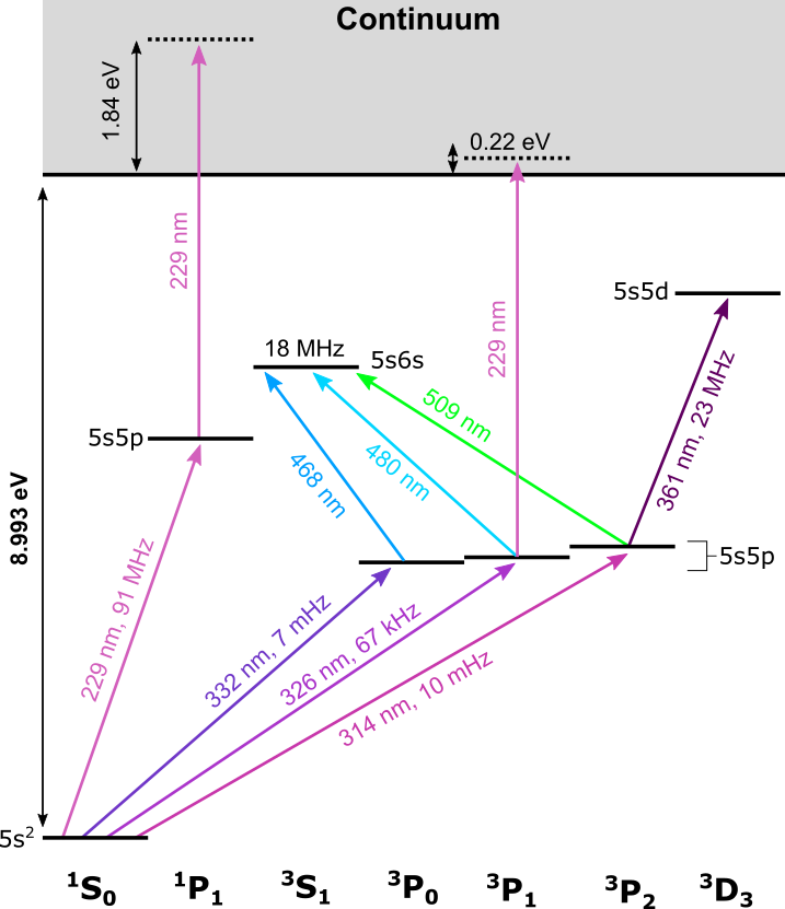
A simplified energy level diagram with allowed transitions for bosonic cadmium is shown in Fig. 1 and further details on the key 1S0-1P1 and 1S0-3P1 transitions for laser cooling and trapping are given in Table 1, with the values for the same transitions in the more commonly employed Sr and Yb also provided for comparison. In this section, we will discuss these two transitions in detail and highlight how their features guide our cooling and trapping apparatus design, also considering the requirements highlighted above.
| Atom | (nm) | (mW/cm2) | (∘C ) | (m/s) | (m) | ||
|---|---|---|---|---|---|---|---|
| 1S0-1P1 (First-stage) | |||||||
| Cd | 228.9 | 91 MHz | 991 | 2.2 mK | 100 | 288 | 910-3 |
| Sr | 460.9 | 32 MHz | 42.5 | 0.8 mK | 280 | 397 | 810-2 |
| Yb | 398.9 | 28 MHz | 57.7 | 0.7 mK | 240 | 272 | 710-2 |
| 1S0-3P1 (Second-stage) | |||||||
| Cd | 326.1 | 66.6 kHz | 0.252 | 1.6 K | 100 | 288 | 18 |
| Sr | 689.4 | 7.4 kHz | 0.003 | 180 nK | 280 | 397 | 513 |
| Yb | 555.8 | 182.2 kHz | 0.139 | 4.4 K | 240 | 272 | 16 |
The dipole-allowed transition 1S0-1P1 has two very noticeable features: a short wavelength of 229 nm lying in the deep-ultraviolet (DUV) regime; and a very broad natural linewidth (291 MHz) [34]. Both these features present technical challenges in implementing an optimised practical realisation of a cold Cd atom source. Ideally, the system would be operated close to the saturation intensity to saturate the cooling and trapping forces, but given the very high saturation intensity of the main broad cooling transition (991 mW/cm2), this would require high continuous-wave powers at 229 nm which is problematic for a number of technical and fundamental reasons.
Firstly, the laser sources and the optics in the DUV regime are still under progress and are relatively less developed in comparison to visible or infrared regime. Although UV lasers are constantly improving, the regime below approximately 240 nm remains highly challenging. For example, recent advances using CLBO crystals to generate 2 W of stable power at 261 nm [35] cannot be directly applied due to the phase-matching properties of CLBO, which has a Type-I SHG cut-off wavelength at 237 nm [36]. Instead beta-barium borate (BBO) crystals have to be used, which exhibit greater DUV-induced damage [37], and achieving such powers stably over significant timescales (hours) has not currently been demonstrated. Additionally, many optical components are not readily available at this wavelength. For example, while single-mode fibres for the UV have been demonstrated, they are not commercially available and require a complex production procedure for a still limited performance [38, 39].
Moreover, even if W-level power at 229 nm were available, it is not clear that it would be advantageous for a practical experiment with Cd atoms. One issue is that at this short wavelength, Cd atoms are prone to photoionisation from both the 1P1 and, potentially, the 3P1 states (Fig. 1), which will practically limit the number of atoms which can be loaded into a MOT [20]. For example, the expected loss rate due to photoionisation can be calculated according to , where is the beam intensity, is the fraction of atoms in the 1P1 state and = cm2 [20], meaning that for a MOT using 6 beams with =150 mW, =2 mm (=2400 mW/cm2, =2.4) and detuning =, we obtain a photoionisation loss rate 1.2 kHz which represents a significant loss for the MOT. Furthermore, high-power DUV light is damaging to optical coatings, especially those under vacuum, leading to degradation of performance. The complete damage mechanisms are not fully understood, though there seems to be contributions from both oxygen depletion of the coating material and from various UV-induced mechanisms related to hydrocarbon contamination [40, 41]. Although research into improving optical coatings under vacuum is ongoing [41, 42] and fluoride-based coatings seem to perform much better [43], this problem is not currently solved. Excessive use of 229-nm light would therefore require the system to be regularly opened or purged to recover the coating performance.
Also mentioned in Table 1 is the large linewidth of the 229-nm transition. For the development of the MOT on this transition with high scattering rate, high magnetic field gradients are prescribed. For example, a MOT can be modelled as a damped harmonic oscillator [44] and we estimate that critical damping requires a gradient of G/cm for saturation intensity =0.2 and detuning =. Such a requirement would rule out the usage of water-cooled magnetic coils not only due to the sheer blockage of optical access, but also the possibility of eddy currents arising from switching the large currents (100 A).
However, this combination of the short wavelength and broad natural linewidth does prevent significant advantages if utilised correctly. It allows for a very large deceleration force on the atom which can, for example, dramatically shorten the length of the Zeeman slower stage where the atoms from the room temperature are cooled down to tens of m/s over a distance of cm. For example, the computed minimum stopping distance for atoms travelling at a speed =290 m/s is only 9 mm (Table 1). Furthermore, the broad transition means that the approximate capture velocity of any MOT can potentially be large at practical values (50 m/s), making it easy to capture atoms from e.g. a relatively fast atomic beam.
The Doppler temperature of the 1S0-1P1 is, however, higher than desirable at 2.2 mK, so in any case further cooling is mandatory. Alkaline-earth and alkaline-earth-like systems typically achieve cooling to the necessary K regime by using a second-stage MOT on the narrow 1S0-3P1 intercombination transition, with the laser frequency modulated to enhance its scattering force [45]. Although this transition is also in the UV regime for Cd at 326 nm, it is considerably less challenging and powers approaching the W-level around this wavelength can be more readily achieved [46, 28, 47].
One intriguing possibility is the direct loading into the intercombination-transition MOT of an atomic beam of Cd, something which is routinely performed for Yb with loading rates of 108 atoms/s [48], but is far more challenging for Sr, though possible in a carefully optimised system [26]. As shown in Table 1 the linewidth of the 1S0-3P1 transition of Cd lies between these two cases, suggesting a difficult but achievable process, as also suggested by the similarity in the stopping distance of Cd and Yb (Table 1). The drawback of this technique is that the capture velocity of the MOT will be limited to 5 m/s, so only a very small fraction of room-temperature atoms can captured if used on its own.
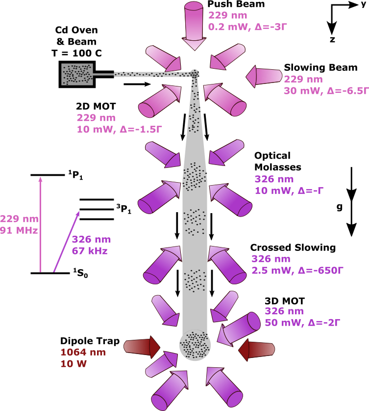
III Overview & Idea of the system
The basic idea of system is shown in Fig. 2, inspired by previous systems with other species [25, 26]. In brief, the main guiding principle was to minimise the amount of 229 nm light required and to separate the cooling based on the broad and narrow transitions at 229 nm and 326 nm, respectively, principally due to the aggressive and problematic nature of 229 nm light discussed above (see Section II)
Cadmium atoms will be emitted from an oven at 100 ∘C to form an effusive atomic beam which is loaded into a 2D MOT on the broad 1S0-1P1 transition at 229 nm. Unlike a 3D MOT, this system does not have steady-state trapping of the Cd atoms and therefore reduces the interaction time of the atoms with the 229 nm light. The magnetic field for a 2D MOT can furthermore be generated with a simple arrangement of permanent magnets [25], removing the requirement of high electrical currents otherwise necessary for generating of the required large gradients (200 G/cm). The loading rate of this 2D MOT can be optionally enhanced by using a transverse-field Zeeman slowing beam, without the need for further magnets.
A low-intensity push beam will both plug the 2D MOT in the non-trapping dimension and direct the atoms from the 2D MOT vertically downwards towards a chamber, around 35 cm beneath the 2D MOT, where they will be loaded directly into a 3D MOT based on the narrow 1S0-3P1 326 nm transition. Separating these two MOTs spatially, rather than temporally, is beneficial for improving vacuum quality and potentially allows for a continuous flux of cold atoms [26, 22]. In the specific case of Cd, there are additional practical benefits to separating the MOT regions; for example, this design lessens the problem of photoionisation by reducing the interaction time with the 229 nm light (see Section V) and protects the weak 3D MOT from the strong 229-nm photons.
For an atomic beam with a longitudinal velocity below the capture velocity of 5 m/s, the acceleration due to gravity begins to play a non-trivial role. For example, for an estimated transit distance of 30 cm, atoms with an initial longitudinal velocity in the horizontal direction of 4 m/s will fall 3 cm off axis. This would therefore require the 3D MOT to be carefully placed off the beam-axis and for the vacuum chamber to incorporate potentially non-trivial geometries. This is a known complication when trying to load directly on the intercombination transition of Yb systems [49]. We circumvent this problem by instead separating the two MOT chambers along the vertical axis, exploiting the acceleration due to gravity to help the atoms fall towards the 3D-MOT region [26]. This has the additional benefit of reducing the required power of the push beam, helping to protect the intercombination-transition MOT from the more powerful dipole-transition light.
The loading of the 3D MOT will also be enhanced by including two additional stages of cooling on the 326 nm transition: firstly in the transverse direction in optical molasses; and then using a pair of angled and crossed beams to slow in the longitudinal (vertical) direction. The combination of the relatively fast transverse velocity due to the high Doppler temperature of the 1S0-1P1 transition with the slow longitudinal velocity results in a divergent atomic beam ( 100 mrad). The transverse cooling is therefore required for collimation of the slow atomic beam coming from the 2D MOT, without which only a small fraction of the atoms would be capturable in the 3D MOT. The additional longitudinal slowing is less critical, but allows for a greater fraction of atoms to be captured by reducing the vertical component of the velocity gained during free fall. These beams are so-called crossed (or angled) slowing beams, a geometry which avoids interference with the 3D MOT itself and as has been demonstrated effectively in e.g. Dy, Er and Yb systems [50, 51, 52].
IV Numerical Simulation of Atomic Trajectories
We numerically simulate the atomic trajectories of our system using pseudorandom sampling and the Monte Carlo method, implementing this process on Python. This technique has been successfully applied previously to simulate a broad variety of MOTs and MOT-based atomic beam sources, including standard 3D and 2D implementations [53, 54, 55], to more unconventional configurations such as pyramidal [56] and Rydberg-dressed systems [57].
The atomic trajectories are determined for a pseuedorandomly drawn initial position and velocity and by stepping the time sequentially and using the calculated acceleration due to radiation pressure to update the atom’s position and velocity for the next time step. Although it is possible to perform a quantum full simulation of MOT dynamics [58], we instead chose temporal step sizes such that so that the atom-light interaction can be treated in a semi-classical manner. As different regimes of the simulation are dominated by different transitions with highly different linewidths, we alter this time step accordingly and also in a trade-off between accuracy and computational time, but is typically 50 s. The total end time for the simulation is made longer than generally required (500 ms), with the simulation of each atom instead stopped when it fulfils certain criteria, such as leaving a certain spatial range or becoming trapped in the MOT.
The starting point of our simulation is an effusive atomic beam. Collimated sources of Cd have previously been demonstrated, continuously with a capillary-based oven system with a divergence 40 mrad [27], and in a pulsed manner using laser ablation [24]. Here we model an oven with a simple single 32-mm long, 1-mm diameter capillary, for which the Knudsen number 1 at 100 ∘C, taking a Van der Waals radius of 158 pm for Cd [59], meaning intra-atomic collisions can be ignored. Although the longitudinal and transverse velocity distributions from a capillary-based oven are known [60, 61], it is not possible to sample from them independently, due to the permissible range of transverse velocities for successfully exiting the capillaries depending upon the longitudinal velocity. We instead use the Monte-Carlo method to generate three velocity components using the Maxwell-Boltzmann distribution and geometrically determine whether these atoms will exit our oven design. This simulation is performed until the desired number of atoms have successfully exited the capillary, which is typically 104. The generated transverse velocity distributions of this simulation match the theoretical distribution well [61, 62], as shown in Fig. 3.
All the laser beams are modeled as perfect Gaussian beams, with a sharp truncation introduced by the diameter of the vacuum viewport they will be shone through. We determine the local light-induced acceleration by these beams at each position and velocity by considering a model that includes the vector of the local magnetic field, not just the field magnitude [63]. In this model, the polarisation of the light is decomposed into its different , and components, following the quantisation axis provided by the local magnetic field direction. This allows for a more accurate determination of the scattering force at arbitrary 3D fields and positions within our simulation, for example when the atom is not along the beam axes. Finally, when simulating the 1S0-3P1 transition, we typically assume that the laser beam is frequency modulated. This technique is often used to enhance the trapping potential of MOTs on intercombination transitions [45]. We model this by assuming the total power of the laser beam to be evenly distributed between the frequency modes.
Following this formalism [63] and adjusting for the possibility for multiple frequency modes, we can write the acceleration due to the laser beam, propagating in the direction of a unit vector with intensity and operating on a transition with natural linewidth and vacuum wavelength :
| (1) |
where is the saturation parameter of a single frequency mode and is the combined saturation parameter from all beams [63, 64], is the detuning of the mode in units of linewidth, , with the Bohr magneton, and is the atomic mass, v the atomic velocity and is unit vector of the magnetic field at the position in question. We concentrate on the bosonic isotopes of Cd for which is 1 and for the 229 nm and 326 nm MOT transitions, respectively. The , and components are accounted for by the summation over and with = -1, 0, 1, respectively. The parameter which is given by and , where 1 is the handedness of the circularly polarised light relative to the propagation direction [63]. We also extend this formalism to account for linear polarisations, as well as circular. In this case we instead use and /2, where is the unit linear polarisation vector of the beam.
The details of the various magnetic field calculations are given in the relevant sections below, but in all cases we first calculate a field on a spatial grid across the full experimental region. These calculations are then linearly interpolated and saved for computational efficiency, allowing for the determination of the total magnetic field from all sources at any spatial points within the simulation region. Combined with Eq. 1, this means that the we can simulate the light force at all points. Earth’s magnetic field is assumed to be consistent and cancelled and therefore not considered.
In addition to determining the acceleration due to each beam, we also use Eq. 1 to estimate the total scattering rate . This can then be used to model the heating effect of spontaneous emission via the addition of a random momentum kick , where is a unit vector chosen pseudorandomly from an isotropic distribution [56, 55]. In this way, the temperature of the atoms is limited to the Doppler temperature [65] instead of continuing to decrease towards zero, which is important for correctly understanding the behaviour of the 1S0-1P1 transition stages (Sec. V) where the 2.2 mK Doppler temperature leads to non-negligible residual velocities.
V The 2D-MOT, Zeeman Slower and Push Beam at 229 nm
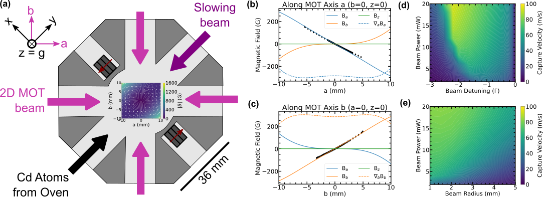
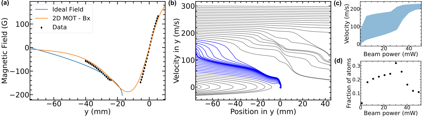
The first-stage of cooling and trapping of our design is to load atoms from the effusive beam into a 2D MOT. We have designed a compact chamber with cut-out regions that allow for permanent magnets to be placed at a minimum distance of 22 mm from the MOT centre, but to remain external to the vacuum chamber for experimental ease (Fig. 4). With two stacks of three permanent bar magnets each (neodymium, 25103 mm3, M9105 A/m), we can generate magnetic field gradients of 250 G/cm which are approximately uniform across the MOT region. A set of three magnets is the maximum possible with our chamber design and it produces a higher capture velocity than a set of one or two. Although analytic solutions for the field produced by bar magnets exist [66], we find minimal deviations when modelling the magnets as point-source dipoles. Fig. 4 shows both the calculated and measured magnetic field profiles, as determined with a Hall probe, which are in good agreement.
We can use this field to estimate the capture velocity, to the nearest m/s, of the 2D MOT using the simulation method outlined in the previous section. In these simulations we use atoms without transverse velocity and remove the random heating arising from scattering, effectively therefore only considering cooling and trapping in 1D. We perform this simulations for a range of beam powers, beam radii, and frequency detunings, showing that capture velocities approaching 100 m/s are achievable for this configuration (Fig. 4). We find that for a reasonable 229 nm power of just 10 mW per beam and with a beam radius of 2 mm and a detuning of 1.5 , this configuration can achieve capture velocities of 70 m/s. This beam radius is chosen to match the atomic beam size at the 2D MOT position (Fig. 3 (d)). The high capture velocity is a positive feature of the 229-nm transition, arising from the large accelerations achievable due to the low wavelength and high linewidth (see Table 1). Although increasing the power can improve the performance (Fig. 4), we limit the power to 10 mW to be comfortable for long-term production of current laser technology [27] and to protect the vacuum viewports. Likewise we use a detuning of 1.5 to be within a region which is immune to frequency and intensity fluctuations, as the capture velocity drops dramatically with increasing detuning or declining intensity following the optimum value. The resulting 70 m/s capture velocity will allow for appreciable atom numbers to be loaded into the 2D MOT directly from an effusive beam or vapour, as studied later in Section VII.
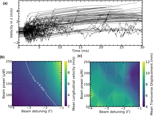
Following trapping in the 2D MOT, we can consider the case of a low-intensity push beam orthogonal to the 2D-MOT plane, which serves the purpose to plug the atoms in one direction and to accelerate them in the other, generating a slow beam of atoms. This beam is low-intensity to reduce the 229-nm power requirements, to maintain a small velocity of the output atoms, and to not interfere with the 326-nm MOT which is placed directly vertically below (see Section VI). By incorporating the push beam, we can simulate the interaction time with the 229 nm light in the 2D MOT and push beam, finding it to be just a few ms (Fig. 5 (a)). For comparison, a steady-state 3D MOT on this transition with similar beam parameters is loaded for at least 200 ms [5]. The expected losses due to photoionisation for our system are therefore around only 2%, given a calculated value of =4 Hz, and such losses can be considered negligible.
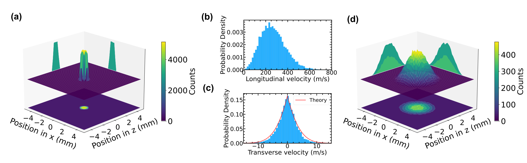
To investigate the output atomic beam we simulate atoms from our atomic oven which are then slowed and trapped in the 2D-MOT and exit along the axis of the push beam for a range of experimental powers and frequency detunings, with the beam radius fixed at 3 mm to be larger than the size of the 2D MOT. In Fig. 5 we consider the output velocity and positional spread of such atoms at a vertical distance of mm from the 2D-MOT centre, with a target axial velocity of around 4 m/s. At this distance, the force from the push beam has become small and the velocity distribution is largely fixed (Fig. 5 (a)). The longitudinal velocity of the output atomic beam is controlled by the intensity of the push beam and its detuning, as shown in Fig. 5 (b). The advantage of increasing the frequency detuning is that the sensitivity to power fluctuations is reduced, for example, decreasing the sensitivity by a factor 2 when increasing the detuning from 2 to 3. Even at =3, however, only 150 W is required for =4 m/s. For the specific case of a push beam power of 170 W and =3, the simulated distribution is shown in Fig. 6, giving an axial velocity centred around 4 m/s with a transverse spread of 0.5 m/s, compatible with the Doppler temperature. With such a velocity distribution, the mean transverse displacement from the vertical axis also remains modest over short distances (10 mm at 50 mm displacement), though subsequent transverse cooling on the narrow 326-nm intercombination transition is mandatory, as discussed later (Section VI).
We finally consider the possibility of enhancing the atom number in the 2D MOT by use of a Zeeman slowing beam. Generating these fields over the short distances requested (60 mm) is challenging, even with permanent magnets. For example, while permanent magnets in Halbach arrays have been used and studied in detail for Zeeman slowers with e.g. Rb [66, 67] and Yb [49], the generated fields had gradients of 3 G/cm [66], 12 G/cm [67] and 20 G/cm [49], an order of magnitude lower than what is requested in this case (100 G/cm). Such gradients are difficult to design, especially without affecting the magnetic field in the 2D MOT region.
However, the negative gradient slope of the 2D MOT field makes a reasonable approximation of a transverse field Zeeman slower, as shown in Fig. 7 (a). This field requires linear polarisation orthogonal to the magnet field direction [68], which is therefore equally decomposed into and components. Only half the input power is therefore available to drive the needed for our decreasing field configuration, effectively doubling the power requirements compared to a longitudinal field Zeeman slower [69], which runs counter to the design idea of minimizing the required 229-nm power (see Section III).
Nevertheless, the performance of a Zeeman slower using this field is shown in Fig. 7 as a function of the slowing beam power. The beam waist is 2 mm (focused at the oven output) and the detuning to match the ideal field as closely as possible. The range of oven output velocities captured by the 2D MOT is shown, as atoms that are too slow can be pushed backwards by the Zeeman slower beam, especially at higher powers (Fig. 7 (c)). This range can be approximately converted into a normalized atom number by integrating the longitudinal velocity distribution of the oven output (see Fig. 3) within the capture velocity range. As can be seen in Fig. 7 (d), at 30 mW of power the fraction of atoms it is in principle possible to load into the 2D MOT is increased to 30%, an order or magnitude improvement from the case without the Zeeman slower. Due to this large required beam intensity, the Zeeman slower is in general ignored in the subsequent analysis and discussion.
VI Direct Loading of a 3D-MOT at 326 nm
Whilst the broad dipole-allowed 1S0-1P1 transition allows for efficient slowing of the fast atoms from the longitudinal beam, the Doppler temperature of 2.2 mK is impractical for either direct performance of atom interferometry or for further cooling in an optical dipole trap (see Section VIII). Further cooling with the 1S0-3P1 transition is therefore required, as discussed in Section II, and we propose to directly capture the slow atomic beam exiting the 2D MOT into a MOT based on this transition.
To understand the feasibility of this approach, we first numerically determine the capture velocity of a Cd MOT at 326 nm, for a broad range of experimentally realistic parameters. In simulating this process, we consider copper-wire coils wound around a standard DN100CF flange (see Section VII for vacuum system details), and calculate the generated magnetic field analytically along the axial direction and numerically otherwise, and perform a linear interpolation between these points. We assume usable laser powers of up to 100 mW per beam in a retro-reflected configuration, based on our recently developed system [28].
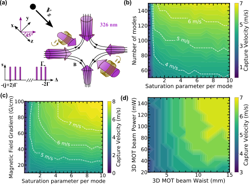
We determine the the capture velocity for a broad range of parameters for atoms travelling along the vertical direction and with the MOT beams propagating through the coils along the axis and the other beams at 45∘ to the and axes in the plane. (Fig. 8 (a)). Figures 8 (b) and (c) show that the capture velocity can be 5 m/s for a large range of feasible parameters in terms of magnetic field gradients and frequency modulation given the available power. In the case of a magnetic field gradient =30 G/cm, as used previously for this MOT [5] and 100 frequency modes evenly separated by (6.6 MHz amplitude), we find that beams with radii 5 mm are required to capture atoms at =5 m/s (Fig. 8 (d)).
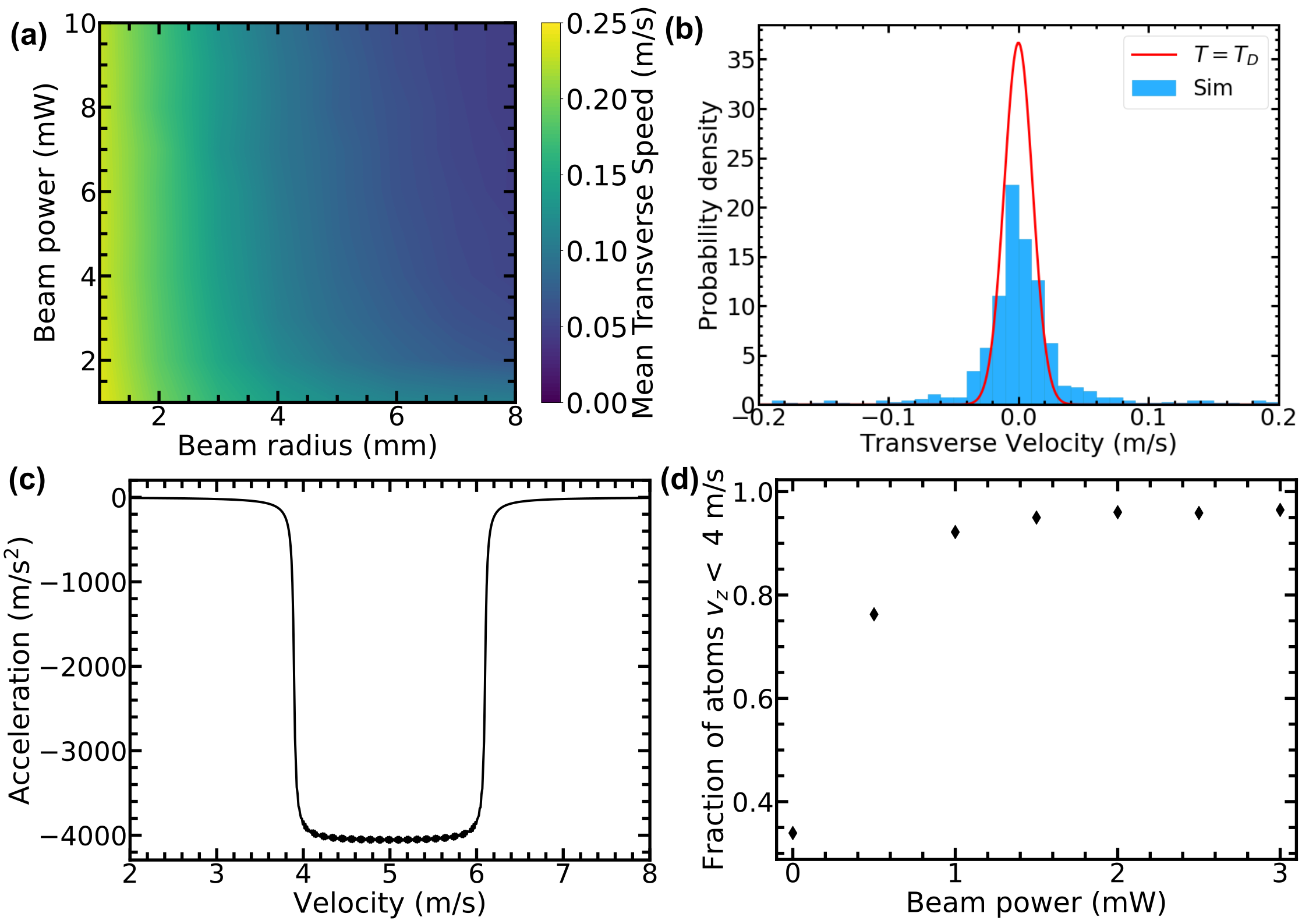
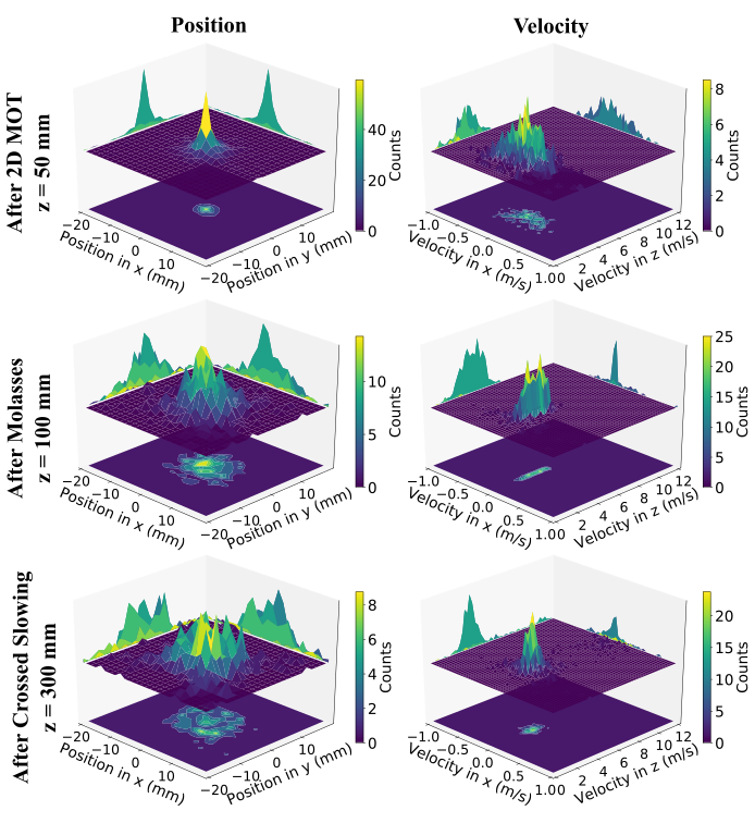
While the first-stage of cooling produces a beam of atoms sufficiently slow to be captured by this MOT (see Section V), a problem arises in the that the transfer distance from the 2D to 3D MOT will be 35 cm, based on standard vacuum components and other considerations such as differential pumping. Due to the slow longitudinal velocity and high Doppler temperature of the 229 nm transition, the atoms will diverge significantly over this distance (see Fig. 6). We therefore simulate transverse cooling 85 mm below the 2D MOT in 2D optical molasses with the 1S0-3P1 transition, which effectively collimates the slow atomic beam. The slow atomic beam after the molasses is shown in Fig. 6 for the case of 10 mW per 5 mm radius beam with 100 frequency modes. The transverse velocity spread has been reduced to 0.05 m/s, an order of magnitude reduction. The lack of cooling in the longitudinal direction does cause some heating, though this is not seen to be significant.
Furthermore, as shown in Fig. 9 (a), this cooling is effective for a broad range of beam powers and radii, requiring a beam radius 4 mm and powers 2 mW to approach optimal transverse cooling. The transverse velocity distribution approaches the Doppler limit (Fig. 9 (b)) and substantial transverse cooling can be achieved for even low powers. Moreover, we find that this cooling can occur relatively rapidly over just 2 ms, with reasonable power levels (10 mW per beam, radius 5 mm) and frequency modulations (100 modes). This cooling is also stronger than the contribution of the 229 nm scattered from the 2D MOT. To estimate the effect of this on the atoms, we consider a worst-case scenario of all the input light being scattered resonantly and isotropically from the MOT centre. At the molasses position, the force from this scattered light is two orders of magnitude lower than the force from a single beam of the molasses and it is therefore taken to have a negligible effect.
The capture efficiency of the MOT can be further enhanced by using vertical slowing on this output of the 2D molasses. We consider a pair of crossed slowing beams aligned with a full angle of 16∘ and again on the 326 nm transition. Assuming 100 frequency modes, the acceptance velocity range of the force is 2 m/s (Fig. 9 (c)), meaning the detuning must be carefully selected in order to slow the desired atoms, also accounting for the non-negligible Zeeman shifts arising from the MOT coils (see Eq. 1). In our case this corresponds to a detuning of =650 (43 MHz) to slow the atoms to a minimum velocity of 4 m/s. With just a few mW of power, the crossed slowing of atoms increases the fraction of atoms with a longitudinal velocity 4 m/s from 30% to 95% (Fig. 9 (d)). As shown in Fig. 6, this slowing process produces only minimal heating in the transverse direction and the slow atomic beam from the 2D MOT has therefore been both collimated for efficient transport and further cooled to below the 3D MOT capture velocity.
VII Full Vacuum Apparatus & MOT Loading Rates
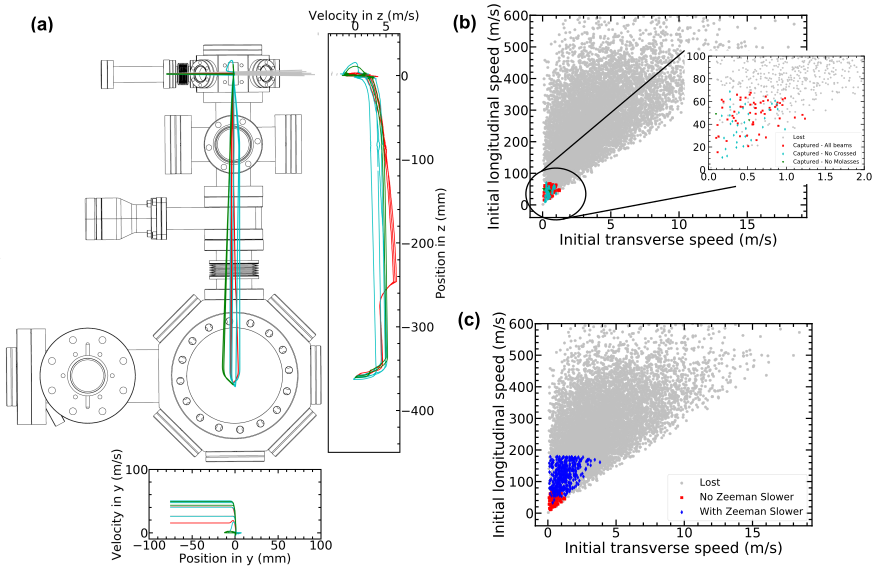
We utilise the results of the preceding sections to design a vacuum system capable of generating a cold beam of Cd which can be loaded into a MOT on the 326-nm 1S0-3P1. A to-scale diagram of the design is shown in Fig. 10. The 2D and 3D MOT regions are each pumped with an ion pump and non-evaporable getter and are separated by a gate valve to allow for the replacement of viewports in the case of UV-induced damaged, without having to open the whole system. This geometry also provides the finalised distances for the different cooling stages, namely the molasses cooling 85 mm below the 2D MOT and the crossed slowing 100 mm above the 3D MOT, which is itself 350 mm below the 2D MOT. With this finalised design, we are able to simulate the atomic trajectories throughout the whole system at a range of oven temperatures and estimate the atomic loading rate into the 3D MOT, a more useful experimental parameter than e.g. the capture velocity used above.
Information on all the simulated beam powers, radii, frequency detuning etc. is given in Table 2. We first attempt to quantify the effect of the different stages of our design, by running the simulation at =100 ∘C (partial pressure of 2.510-7 mbar, flow rate of 1.11010 atoms/s) with and without the Zeeman slower and the crossed (vertical) and transverse cooling at 326 nm. We find that the introduction of the transverse slower increases the capture efficiency by more than an order of magnitude and with the introduction of vertical slowing it increases by another factor 3 (Table 3), for an approximate total factor of 40 in the efficiency. As Fig. 10(b) shows, with these two cooling stages active, nearly all of the atoms below the capture velocity of the 2D MOT are captured by the 3D MOT, showing that the transfer between the MOTs is highly efficient. Adding the Zeeman slower leads to a substantial increase in the capture efficiency, by capturing a higher initial longitudinal velocity class in the 2D MOT, as shown in Fig. 10(c).
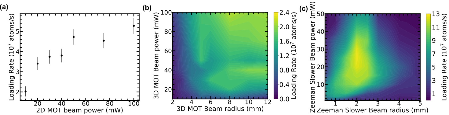
As shown in Table 3, we estimate expected loading rates into our 3D MOT and find values 107 atoms/s for an oven temperature of 100 ∘C, without the Zeeman slower. When adding the Zeeman slower beam, this increases by approximately a factor 5 to 108 atoms/s, though at the cost of a substantial increase in the required 229 nm power. The loading rate is determined by calculating the expected flow rate of atoms at the simulated oven temperature and capillary design and then multiplying this by simulated capture efficiency. We further scale the loading rate based on the fractional natural abundance of the 114Cd isotope of 0.29 [70]. Although we have designed the system to work with a minimal amount of 229 nm light, we note that the system is scalable should problems such as stable power production and vacuum viewport damage be solved (see Section II). In addition to allowing for a Zeeman slower, this would allow for an increase in the 2D MOT beam powers, resulting in an approximate threefold increase in loading rate (Fig. 11).
The parameters presented in Table 2 can also be varied to look for the optimum loading rate, especially the effect of the 3D MOT beams and the Zeeman slower. Figure 11 shows that the loading rate is robust for a broad range of 3D MOT beam powers and beam radii (100 frequency modes), provided the power is 10 mW and the beam radius 3 mm. The Zeeman slower beam shows a maximum loading rate which differs slightly from what would naïvely be expected from looking only at the velocity class addressed by the slowing beam (cf. Fig. 7 (d) and Fig. 11 (c)). This is due to the small force imbalance the Zeeman slower introduces to the 2D MOT, which can deflect the slow atomic beam off axis, especially when the Zeeman slower beam radius exceeds the 2D MOT beam radius. Substantial increases in loading rates are available (factor 5), even for powers down to around 10 mW with a focused beam (2 mm).
It should be noted that these loading rates represent the upper bound for the loading rate as our single-atom simulation does not consider losses such as collisions with background gases or other cold Cd atoms, as well as photoionisation losses. Nevertheless, they suggest that significant numbers of atoms can be quickly loaded into an intercombination transition MOT without the need for significant powers or interaction times with the problematic 229 nm 1S0-1P1 transition. The loading rates presented can also be enhanced by increasing the oven temperature above the modest 100 ∘C used here, and by an approximate factor 3 by using enriched cadmium sources, as have been employed previously elsewhere [5, 71].
| Beam (number) | (mW) | (mm) | () | Modes | s |
| 229 nm – 1S0-1P1 | |||||
| 2D MOT (4) | 10 | 2 | -1.5 | 1 | 0.16 |
| Push beam (1) | 0.17 | 3 | -3 | 1 | 10-3 |
| Zeeman Slower (1) | 25 | 2 | -6.5 | 1 | 0.4 |
| 326 nm – 1S0-3P1 | |||||
| 3D MOT (6) | 50 | 5 | -2 | 100 | 5.1 |
| Transverse Cooling (4) | 10 | 5 | -1 | 100 | 1.0 |
| Crossed Slowing (2) | 2.5 | 3 | -650 | 100 | 0.71 |
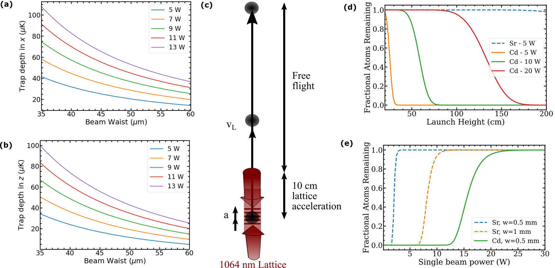
VIII Trapping, Transfer & Launching at 1064 nm
Although the micro-Kelvin temperatures achieved in the 326-nm MOT [5] are sufficient for many applications, producing quantum degenerate sources requires further cooling towards the nK level. This is typically achieved by performing evaporative cooling in an optical dipole trap [72, 73], neither of which techniques have been demonstrated with Cd yet. In this section we consider the feasibility and prospects of this approach and also the discuss the transfer and launching of Cd atoms using related techniques, with particular reference to a dual-species interferometer with Sr [9].
We consider bosonic Cd atoms in the ground state and consider the two-level system made with the 1P1 level. In this approximation the optical dipole potential can be calculated according to [74],
| (2) |
where and are, respectively, the angular frequency and intensity profile of the trap light, and and are the natural linewidth and angular frequency of the two-level system, respectively, in this case the 1S0-1P1 transition.
As is clear from Eq. 2, Cd is not especially suited to trapping in this manner due to the reduced trap depth coming from the necessarily large values of and especially . Nevertheless, for a optical dipole trap formed from two focused beams at 1064 nm crossing at an angle of 60∘ in the horizontal plane, trap depths in excess of 30 K can be achieved with reasonable powers and waists (Fig. 12 (a) and (b)). Commercial lasers at this wavelength can readily produce powers 40 W and with M1.1. This means that efficient loading into a dipole trap from the 3D MOT (K) will be available. Due to the lack of known cold collisional properties of Cd, however, it remains to be seen which isotopes or isotope mixture will be suitable for evaporative cooling. In any case, the optical dipole trap can also serve as the initial stage in transferring the prepared atoms 40 cm into the science chamber of a dual-species interferometer [9]. This transfer can also be performed using a 1064 nm laser, with a single shifting focus beam using an optically compensated zoom lens [75], for which similar waists and powers are needed.
| Efficiency | Loading Rate (atoms/s) | |
|---|---|---|
| 2D MOT & 3D MOT | 0.02 % | 6 4 105 |
| + Transverse Cooling | 0.34 % | 1.0 0.2 107 |
| + Crossed Slowing | 0.85 % | 2.6 0.3 107 |
| + Zeeman Slower | 4.13 % | 12.6 0.6 107 |
The free evolution time of the atom interferometer can be enhanced by launching the atoms in a fountain configuration. A dual-species launch requires that an accelerating lattice be used with sufficient trap depth for both atom species, if the atoms are to be simultaneously launched with the along the same spatial trajectory and with the same velocity, a key requirement for minimising systematic errors, although the difference in mass of the two species will result in different trajectories following the application of the interferometry beams. A standing wave based on a high-power 1064-nm laser is well-suited to this task and we calculate the expected launch efficiencies for both Cd and Sr (Fig. 12 (c)). Our model considers losses from both spontaneous single-photon scattering, which is low due to the large detunings and launch times, and the considerably larger losses due to Landau-Zener tunnelling [76]. To estimate the losses due to Landau-Zener tunnelling, we consider the launch as a sequence of Bloch oscillations and first estimate the trap depth using Eq. 2, considering a retro-reflected standing-wave configuration [77]. This computed trap depths can be used to determine the band gap energies by numerically solving the Schrödinger equation [78]. For a launch velocity , the fraction of surviving atoms is then given by [79],
| (3) |
where is the band gap energy, is the chirp rate of the lattice frequency, and is the number of avoided crossings that the atoms pass through and is the lattice wavenumber. Eq. 3 shows that large trap depths and slow chirp rates minimise tunnelling losses.
Figures 12 (d) and (e) shows the expected losses for both Cd and Sr as a function of the laser beam power for a final launch height of 1 m and with a lattice acceleration distance of 10 cm. For the used waist of 0.5 mm, the Rayleigh length is 0.7 m and so larger than the launch region. Here the losses from Cd are clearly considerable unless high powers are used due to the reduced depth from the 1/ dependence of Eq. 2. This is a more serious issue than for the crossed optical dipole trap, though the required powers for a launch of 1 m with reasonable levels of atom losses (e.g. 50%) are still experimentally feasible (15 W).
The above considerations have assumed that the launch velocity is continuous, whereas in reality it is quantised according to the momentum imparted by the Bloch oscillations of the lattice undergoing an acceleration [76, 78]. There will therefore be a small difference in the launch velocity for different Cd and Sr isotopes arising from their mass difference. Furthermore, as the Bloch oscillation period also depends upon the mass (), different isotopes will not in general undergo an equal number of oscillations during the launch and isotopes will be launched in superpositions of momentum states. However, careful selection of the launch characteristics can help suppress these effects, by selecting oscillations close to the ratio of the masses. For example, when considering the two most abundant isotopes, 114Cd and 88Sr, a launch with exactly 631 oscillations, 487. In this case the atoms will be launched to 98 cm and the difference in launch velocities will be 0.2 mm/s and the difference in apogees just 0.08 mm.
IX Conclusion & Outlook
We have presented the design and thorough simulation of a state-of-the-art apparatus for producing ultracold Cd samples. The design is cognisant of the unique challenges of this atomic species, especially the broadband dipole-allowed 1S0-1P1 transition at 229 nm. Specifically, we have simulated that it is possible to efficiently load Cd atoms directly into an intercombination-transition MOT starting from an atomic oven, by first using the 229 nm to generate a slow atomic beam, overcoming problems associated with photoionsiation. Such a segmented architecture may be useful for other alkaline-earth-like elements, especially Zn whose relevant transitions are similar to Cd (214 nm, =271 MHz and 308 nm, =24 kHz) and whose laser cooling and trapping is in its infancy [7].
The design is to be used as a basis for atom interferometry [9], where the intercombination transitions of Cd make it a good candidate for both Bragg interferometry [80] and single-photon clock-transition atom interferometry [14, 47]. Longer term, the device seems compatible with continuous atom laser systems [81] if differential pumping is introduced on the vertical axis, which is currently left free for interferometry beams. Additionally and conversely, it may be noted that the device can also be operated in a pulsed configuration, with the 229 nm only turned on intermittently for bursts lasting the 5 ms or so required to cool and trap in the 2D MOT, whilst the 3D MOT remains on for the whole duration. This may be beneficial for protecting the vacuum windows and the BBO crystal, for which the damage mechanisms are related to sustained exposure to continuous-wave 229 nm. A similar idea has very recently been shown to be highly effective in preventing degradation in an evacuated optical cavity at 244 nm [82].
X Acknowledgments
We thank Aidan Arnold and Stefan Truppe for useful discussions, Nicola Grani and Shamaila Manzoor for initial work on the simulations, and Leonardo Salvi for help with the magnetic field calculations. This work has been supported by the European Research Council, Grant No.772126 (TICTOCGRAV). J.N.T acknowledges the support of the Horizon Europe Grant ID 101080164 (UVQuanT).
References
- Schreck and Druten [2021] F. Schreck and K. v. Druten, Laser cooling for quantum gases, Nature Physics 17, 1296 (2021).
- Poli et al. [2013] N. Poli, C. W. Oates, P. Gill, and G. M. Tino, Optical atomic clocks, Rivista del Nuovo Cimento 36, 555 (2013).
- Safronova et al. [2018] M. S. Safronova, D. Budker, D. DeMille, D. F. J. Kimball, A. Derevianko, and C. W. Clark, Search for new physics with atoms and molecules, Rev. Mod. Phys. 90, 025008 (2018).
- Tino and Kasevich [2014] G. M. Tino and M. A. Kasevich, Atom Interferometry, Proceedings of the International School of Physics “Enrico Fermi,” Course CLXXXVIII, Varenna 2013 (Società Italiana di Fisica and IOS Press, 2014).
- Yamaguchi et al. [2019] A. Yamaguchi, M. S. Safronova, K. Gibble, and H. Katori, Narrow-line Cooling and Determination of the Magic Wavelength of Cd, Phys. Rev. Lett. 123, 113201 (2019).
- Zhang et al. [2021] Y. Zhang, Q. Liu, X. Fu, J. Sun, Z. Xu, and Y. Wang, A stable deep-ultraviolet laser for laser cooling of mercury atoms, Optics & Laser Technology 139, 106956 (2021).
- Büki et al. [2021] M. Büki, D. Röser, and S. Stellmer, Frequency-quintupled laser at 308 nm for atomic physics applications, Appl. Opt. 60, 9915 (2021).
- Lavigne et al. [2022] Q. Lavigne, T. Groh, and S. Stellmer, Magneto-optical trapping of mercury at high phase-space density, Phys. Rev. A 105, 033106 (2022).
- Tinsley et al. [2022] J. N. Tinsley, S. Bandarupally, M. Chiarotti, S. Manzoor, L. Salvi, and N. Poli, Prospects for a simultaneous atom interferometer with ultracold cadmium and strontium for fundamental physics tests, in Optical and Quantum Sensing and Precision Metrology II, Vol. 12016, edited by J. Scheuer and S. M. Shahriar, International Society for Optics and Photonics (SPIE, 2022) pp. 1 – 16.
- Takamoto et al. [2005] M. Takamoto, F.-L. Hong, R. Higashi, and H. Katori, An optical lattice clock, Nature 435, 321 (2005).
- McGrew et al. [2018] W. F. McGrew, X. Zhang, R. J. Fasano, S. A. Schäffer, K. Beloy, D. Nicolodi, R. C. Brown, N. Hinkley, G. Milani, M. Schioppo, T. H. Yoon, and A. D. Ludlow, Atomic clock performance enabling geodesy below the centimetre level, Nature 564, 87 (2018).
- Bothwell et al. [2022] T. Bothwell, C. J. Kennedy, A. Aeppli, D. Kedar, J. M. Robinson, E. Oelker, A. Staron, and J. Ye, Resolving the gravitational redshift across a millimetre-scale atomic sample, Nature 602, 420 (2022).
- Zheng et al. [2022] X. Zheng, J. Dolde, V. Lochab, B. N. Merriman, H. Li, and S. Kolkowitz, Differential clock comparisons with a multiplexed optical lattice clock, Nature 602, 425 (2022).
- Hu et al. [2017] L. Hu, N. Poli, L. Salvi, and G. M. Tino, Atom Interferometry with the Sr Optical Clock Transition, Phys. Rev. Lett. 119, 263601 (2017).
- Badurina et al. [2020] L. Badurina et al., AION: an atom interferometer observatory and network, Journal of Cosmology and Astroparticle Physics 2020 (05), 011.
- Itano et al. [1982] W. M. Itano, L. L. Lewis, and D. J. Wineland, Shift of 2S hyperfine splittings due to blackbody radiation, Phys. Rev. A 25, 1233 (1982).
- Bothwell et al. [2019] T. Bothwell, D. Kedar, E. Oelker, J. M. Robinson, S. L. Bromley, W. L. Tew, J. Ye, and C. J. Kennedy, JILA SrI optical lattice clock with uncertainty of , Metrologia 56, 065004 (2019).
- Haslinger et al. [2018] P. Haslinger, M. Jaffe, V. Xu, O. Schwartz, M. Sonnleitner, M. Ritsch-Marte, H. Ritsch, and H. Müller, Attractive force on atoms due to blackbody radiation, Nature Physics 14, 257 (2018).
- Kaufman and Ni [2021] A. M. Kaufman and K.-K. Ni, Quantum science with optical tweezer arrays of ultracold atoms and molecules, Nature Physics 17, 1324 (2021).
- Brickman et al. [2007] K.-A. Brickman, M.-S. Chang, M. Acton, A. Chew, D. Matsukevich, P. C. Haljan, V. S. Bagnato, and C. Monroe, Magneto-optical trapping of cadmium, Phys. Rev. A 76, 043411 (2007).
- Kaneda et al. [2016] Y. Kaneda, J. M. Yarborough, Y. Merzlyak, A. Yamaguchi, K. Hayashida, N. Ohmae, and H. Katori, Continuous-wave, single-frequency 229 nm laser source for laser cooling of cadmium atoms, Opt. Lett. 41, 705 (2016).
- Chen et al. [2019] C.-C. Chen, S. Bennetts, R. G. Escudero, B. Pasquiou, and F. Schreck, Continuous guided strontium beam with high phase-space density, Phys. Rev. Applied 12, 044014 (2019).
- Schussheim and Gibble [2018] D. Schussheim and K. Gibble, Laser system to laser-cool and trap cadmium: towards a cadmium optical lattice clock (Optical Society of America, 2018) p. LTh1F.2.
- Ohayon et al. [2022] B. Ohayon, S. Hofsäss, J. E. Padilla-Castillo, S. C. Wright, G. Meijer, S. Truppe, K. Gibble, and B. K. Sahoo, Isotope shifts in cadmium as a sensitive probe for physics beyond the standard model, New Journal of Physics 24, 123040 (2022).
- Lamporesi et al. [2013] G. Lamporesi, S. Donadello, S. Serafini, and G. Ferrari, Compact high-flux source of cold sodium atoms, Review of Scientific Instruments 84, 063102 (2013).
- Bennetts et al. [2017] S. Bennetts, C.-C. Chen, B. Pasquiou, and F. Schreck, Steady-State Magneto-Optical Trap with 100-Fold Improved Phase-Space Density, Phys. Rev. Lett. 119, 223202 (2017).
- Tinsley et al. [2021] J. N. Tinsley, S. Bandarupally, J.-P. Penttinen, S. Manzoor, S. Ranta, L. Salvi, M. Guina, and N. Poli, Watt-level blue light for precision spectroscopy, laser cooling and trapping of strontium and cadmium atoms, Opt. Express 29, 25462 (2021).
- Manzoor et al. [2022] S. Manzoor, J. N. Tinsley, S. Bandarupally, M. Chiarotti, and N. Poli, High-power, frequency-quadrupled UV laser source resonant with the 1S0-3P1 narrow intercombination transition of cadmium at 326.2 nm, Opt. Lett. 47, 2582 (2022).
- Ferrari et al. [2006] G. Ferrari, N. Poli, F. Sorrentino, and G. M. Tino, Long-Lived Bloch Oscillations with Bosonic Sr Atoms and Application to Gravity Measurement at the Micrometer Scale, Phys. Rev. Lett. 97, 060402 (2006).
- Itano et al. [1993] W. M. Itano, J. C. Bergquist, J. J. Bollinger, J. M. Gilligan, D. J. Heinzen, F. L. Moore, M. G. Raizen, and D. J. Wineland, Quantum projection noise: Population fluctuations in two-level systems, Phys. Rev. A 47, 3554 (1993).
- Sorrentino et al. [2014] F. Sorrentino, Q. Bodart, L. Cacciapuoti, Y.-H. Lien, M. Prevedelli, G. Rosi, L. Salvi, and G. M. Tino, Sensitivity limits of a Raman atom interferometer as a gravity gradiometer, Phys. Rev. A 89, 023607 (2014).
- Savoie et al. [2018] D. Savoie, M. Altorio, B. Fang, L. A. Sidorenkov, R. Geiger, and A. Landragin, Interleaved atom interferometry for high-sensitivity inertial measurements, Science Advances 4, eaau7948 (2018).
- Quessada et al. [2003] A. Quessada, R. P. Kovacich, I. Courtillot, A. Clairon, G. Santarelli, and P. Lemonde, The Dick effect for an optical frequency standard, Journal of Optics B: Quantum and Semiclassical Optics 5, S150 (2003).
- Xu et al. [2004] H. L. Xu, A. Persson, S. Svanberg, K. Blagoev, G. Malcheva, V. Pentchev, E. Biémont, J. Campos, M. Ortiz, and R. Mayo, Radiative lifetime and transition probabilities in and , Phys. Rev. A 70, 042508 (2004).
- Shaw et al. [2021] J. C. Shaw, S. Hannig, and D. J. McCarron, Stable 2 W continuous-wave 261.5 nm laser for cooling and trapping aluminum monochloride, Opt. Express 29, 37140 (2021).
- Bhar et al. [2000] G. Bhar, P. Kumbhakar, U. Chatterjee, A. Rudra, and A. Nagahori, Widely tunable deep ultraviolet generation in CLBO, Optics Communications 176, 199 (2000).
- Takachiho et al. [2014] K. Takachiho, M. Yoshimura, Y. Takahashi, M. Imade, T. Sasaki, and Y. Mori, Ultraviolet laser-induced degradation of CsLiB6O10 and -BaB2O4, Opt. Mater. Express 4, 559 (2014).
- Gebert et al. [2014] F. Gebert, M. H. Frosz, T. Weiss, Y. Wan, A. Ermolov, N. Y. Joly, P. O. Schmidt, and P. S. J. Russell, Damage-free single-mode transmission of deep-UV light in hollow-core PCF, Opt. Express 22, 15388 (2014).
- Marciniak et al. [2017] C. D. Marciniak, H. B. Ball, A. T.-H. Hung, and M. J. Biercuk, Towards fully commercial, UV-compatible fiber patch cords, Opt. Express 25, 15643 (2017).
- Hollenshead and Klebanoff [2006] J. Hollenshead and L. Klebanoff, Modeling radiation-induced carbon contamination of extreme ultraviolet optics, Journal of Vacuum Science & Technology B: Microelectronics and Nanometer Structures Processing, Measurement, and Phenomena 24, 64 (2006).
- Gangloff et al. [2015] D. Gangloff, M. Shi, T. Wu, A. Bylinskii, B. Braverman, M. Gutierrez, R. Nichols, J. Li, K. Aichholz, M. Cetina, L. Karpa, B. Jelenković, I. Chuang, and V. Vuletić, Preventing and reversing vacuum-induced optical losses in high-finesse tantalum (V) oxide mirror coatings, Opt. Express 23, 18014 (2015).
- Hubka et al. [2021] Z. Hubka, J. Novák, I. Majerová, J. T. Green, P. K. Velpula, R. Boge, R. Antipenkov, V. Šobr, D. Kramer, K. Majer, J. A. Naylon, P. Bakule, and B. Rus, Mitigation of laser-induced contamination in vacuum in high-repetition-rate high-peak-power laser systems, Appl. Opt. 60, 533 (2021).
- Burkley et al. [2021] Z. Burkley, L. de Sousa Borges, B. Ohayon, A. Golovizin, J. Zhang, and P. Crivelli, Stable high power deep-uv enhancement cavity in ultra-high vacuum with fluoride coatings, Opt. Express 29, 27450 (2021).
- Steane et al. [1992] A. M. Steane, M. Chowdhury, and C. J. Foot, Radiation force in the magneto-optical trap, J. Opt. Soc. Am. B 9, 2142 (1992).
- Kuwamoto et al. [1999] T. Kuwamoto, K. Honda, Y. Takahashi, and T. Yabuzaki, Magneto-optical trapping of Yb atoms using an intercombination transition, Phys. Rev. A 60, R745 (1999).
- Hannig et al. [2018] S. Hannig, J. Mielke, J. A. Fenske, M. Misera, N. Beev, C. Ospelkaus, and P. O. Schmidt, A highly stable monolithic enhancement cavity for second harmonic generation in the ultraviolet, Review of Scientific Instruments 89, 013106 (2018).
- Chiarotti et al. [2022] M. Chiarotti, J. N. Tinsley, S. Bandarupally, S. Manzoor, M. Sacco, L. Salvi, and N. Poli, Practical Limits for Large-Momentum-Transfer Clock Atom Interferometers, PRX Quantum 3, 030348 (2022).
- Guttridge et al. [2016] A. Guttridge, S. A. Hopkins, S. L. Kemp, D. Boddy, R. Freytag, M. P. A. Jones, M. R. Tarbutt, E. A. Hinds, and S. L. Cornish, Direct loading of a large Yb MOT on the 1SP1 transition, Journal of Physics B: Atomic, Molecular and Optical Physics 49, 145006 (2016).
- Wodey et al. [2021] E. Wodey, R. J. Rengelink, C. Meiners, E. M. Rasel, and D. Schlippert, A robust, high-flux source of laser-cooled ytterbium atoms, Journal of Physics B: Atomic, Molecular and Optical Physics 54, 035301 (2021).
- Lunden et al. [2020] W. Lunden, L. Du, M. Cantara, P. Barral, A. O. Jamison, and W. Ketterle, Enhancing the capture velocity of a Dy magneto-optical trap with two-stage slowing, Phys. Rev. A 101, 063403 (2020).
- Seo et al. [2020] B. Seo, P. Chen, Z. Chen, W. Yuan, M. Huang, S. Du, and G.-B. Jo, Efficient production of a narrow-line erbium magneto-optical trap with two-stage slowing, Phys. Rev. A 102, 013319 (2020).
- Plotkin-Swing et al. [2020] B. Plotkin-Swing, A. Wirth, D. Gochnauer, T. Rahman, K. E. McAlpine, and S. Gupta, Crossed-beam slowing to enhance narrow-line ytterbium magneto-optic traps, Review of Scientific Instruments 91, 093201 (2020).
- Wohlleben et al. [2001] W. Wohlleben, F. Chevy, K. Madison, and J. Dalibard, An atom faucet, The European Physical Journal D - Atomic, Molecular, Optical and Plasma Physics 15, 237 (2001).
- Chaudhuri et al. [2006] S. Chaudhuri, S. Roy, and C. S. Unnikrishnan, Realization of an intense cold Rb atomic beam based on a two-dimensional magneto-optical trap: Experiments and comparison with simulations, Phys. Rev. A 74, 023406 (2006).
- Barbiero et al. [2020] M. Barbiero, M. G. Tarallo, D. Calonico, F. Levi, G. Lamporesi, and G. Ferrari, Sideband-Enhanced Cold Atomic Source for Optical Clocks, Phys. Rev. Applied 13, 014013 (2020).
- Kohel et al. [2003] J. M. Kohel, J. Ramirez-Serrano, R. J. Thompson, L. Maleki, J. L. Bliss, and K. G. Libbrecht, Generation of an intense cold-atom beam from a pyramidal magneto-optical trap: experiment and simulation, J. Opt. Soc. Am. B 20, 1161 (2003).
- Bounds et al. [2018] A. D. Bounds, N. C. Jackson, R. K. Hanley, R. Faoro, E. M. Bridge, P. Huillery, and M. P. A. Jones, Rydberg-Dressed Magneto-optical Trap, Phys. Rev. Lett. 120, 183401 (2018).
- Hanley et al. [2018] R. K. Hanley, P. Huillery, N. C. Keegan, A. D. Bounds, D. Boddy, R. Faoro, and M. P. A. Jones, Quantitative simulation of a magneto-optical trap operating near the photon recoil limit, Journal of Modern Optics 65, 667 (2018).
- Bondi [1964] A. Bondi, van der Waals Volumes and Radii, The Journal of Physical Chemistry 68, 441 (1964).
- Schioppo et al. [2012] M. Schioppo, N. Poli, M. Prevedelli, S. Falke, C. Lisdat, U. Sterr, and G. M. Tino, A compact and efficient strontium oven for laser-cooling experiments, Review of Scientific Instruments 83, 103101 (2012).
- Gao et al. [2014] F. Gao, H. Liu, P. Xu, X. Tian, Y. Wang, J. Ren, H. Wu, and H. Chang, Precision measurement of transverse velocity distribution of a strontium atomic beam, AIP Advances 4, 027118 (2014).
- Greenland et al. [1985] P. T. Greenland, M. A. Lauder, and D. J. H. Wort, Atomic beam velocity distributions, Journal of Physics D: Applied Physics 18, 1223 (1985).
- Vangeleyn et al. [2009] M. Vangeleyn, P. F. Griffin, E. Riis, and A. S. Arnold, Single-laser, one beam, tetrahedral magneto-optical trap, Opt. Express 17, 13601 (2009).
- Ovchinnikov [2005] Y. B. Ovchinnikov, Compact magneto-optical sources of slow atoms, Optics Communications 249, 473 (2005).
- Letokhov et al. [1977] V. S. Letokhov, V. G. Minogin, and B. D. Pavlik, Cooling and capture of atoms and molecules by a resonant light field, Soviet Journal of Experimental and Theoretical Physics 45, 698 (1977).
- Cheiney et al. [2011] P. Cheiney, O. Carraz, D. Bartoszek-Bober, S. Faure, F. Vermersch, C. M. Fabre, G. L. Gattobigio, T. Lahaye, D. Guéry-Odelin, and R. Mathevet, A Zeeman slower design with permanent magnets in a Halbach configuration, Review of Scientific Instruments 82, 063115 (2011).
- Ali et al. [2017] D. B. Ali, T. Badr, T. Brézillon, R. Dubessy, H. Perrin, and A. Perrin, Detailed study of a transverse field Zeeman slower, Journal of Physics B: Atomic, Molecular and Optical Physics 50, 055008 (2017).
- Ovchinnikov [2007] Y. B. Ovchinnikov, A Zeeman slower based on magnetic dipoles, Optics Communications 276, 261 (2007).
- Hill et al. [2014] I. R. Hill, Y. B. Ovchinnikov, E. M. Bridge, E. A. Curtis, and P. Gill, Zeeman slowers for strontium based on permanent magnets, Journal of Physics B: Atomic, Molecular and Optical Physics 47, 075006 (2014).
- Berglund and Wieser [2011] M. Berglund and M. E. Wieser, Isotopic compositions of the elements 2009 (IUPAC Technical Report), Pure and Applied Chemistry 83, 397 (2011).
- Hofsäss et al. [2023] S. Hofsäss, J. E. Padilla-Castillo, S. C. Wright, S. Kray, R. Thomas, B. G. Sartakov, B. Ohayon, G. Meijer, and S. Truppe, High-resolution isotope-shift spectroscopy of Cd I, Phys. Rev. Res. 5, 013043 (2023).
- Adams et al. [1995] C. S. Adams, H. J. Lee, N. Davidson, M. Kasevich, and S. Chu, Evaporative Cooling in a Crossed Dipole Trap, Phys. Rev. Lett. 74, 3577 (1995).
- Barrett et al. [2001] M. D. Barrett, J. A. Sauer, and M. S. Chapman, All-Optical Formation of an Atomic Bose-Einstein Condensate, Phys. Rev. Lett. 87, 010404 (2001).
- Grimm et al. [2000] R. Grimm, M. Weidemüller, and Y. B. Ovchinnikov, Optical Dipole Traps for Neutral Atoms (Academic Press, 2000) pp. 95–170.
- Lee et al. [2020] J. H. Lee, H. Jung, J.-y. Choi, and J. Mun, Transporting cold atoms using an optically compensated zoom lens, Phys. Rev. A 102, 063106 (2020).
- Peik et al. [1997] E. Peik, M. Ben Dahan, I. Bouchoule, Y. Castin, and C. Salomon, Bloch oscillations of atoms, adiabatic rapid passage, and monokinetic atomic beams, Phys. Rev. A 55, 2989 (1997).
- Hu et al. [2020] L. Hu, E. Wang, L. Salvi, J. N. Tinsley, G. M. Tino, and N. Poli, Sr atom interferometry with the optical clock transition as a gravimeter and a gravity gradiometer, Classical and Quantum Gravity 37, 014001 (2020).
- Kovachy et al. [2010] T. Kovachy, J. M. Hogan, D. M. S. Johnson, and M. A. Kasevich, Optical lattices as waveguides and beam splitters for atom interferometry: An analytical treatment and proposal of applications, Phys. Rev. A 82, 013638 (2010).
- Sugarbaker [2014] A. Sugarbaker, Atom Interferometry in a 10 m Fountain, Ph.D. thesis, Stanford University (2014).
- del Aguila et al. [2018] R. P. del Aguila, T. Mazzoni, L. Hu, L. Salvi, G. M. Tino, and N. Poli, Bragg gravity-gradiometer using the - intercombination transition of 88Sr, New J. Phys. 20, 043002 (2018).
- Chen et al. [2022] C.-C. Chen, R. González Escudero, J. Minář, B. Pasquiou, S. Bennetts, and F. Schreck, Continuous Bose–Einstein condensation, Nature 606, 683 (2022).
- Zhadnov et al. [2023] N. Zhadnov, A. Golovizin, I. Cortinovis, B. Ohayon, L. de Sousa Borges, G. Janka, and P. Crivelli, Pulsed CW laser for long-term spectroscopic measurements at high power in deep-UV (2023), arXiv:2304.13527 [physics.atom-ph] .