english pt
Roadmap for focused ion beam technologies
Abstract
The focused ion beam (FIB) is a powerful tool for the fabrication, modification and characterization of materials down to the nanoscale. Starting with the gallium FIB, which was originally intended for photomask repair in the semiconductor industry, there are now many different types of FIB that are commercially available. These instruments use a range of ion species and are applied broadly in materials science, physics, chemistry, biology, medicine, and even archaeology. The goal of this roadmap is to provide an overview of FIB instrumentation, theory, techniques and applications. By viewing FIB developments through the lens of the various research communities, we aim to identify future pathways for ion source and instrumentation development, as well as emerging applications and opportunities for improved understanding of the complex interplay of ion-solid interactions. We intend to provide a guide for all scientists in the field that identifies common research interests and will support future fruitful interactions connecting tool development, experiment and theory. While a comprehensive overview of the field is sought, it is not possible to cover all research related to FIB technologies in detail. We give examples of specific projects within the broader context, referencing original works and previous review articles throughout.
Acronyms
- AES
- Auger electron spectroscopy
- AFM
- atomic force microscopy
- API
- application programming interface
- APT
- atom probe tomography
- ASIS
- atomic-size ion source
- BCA
- binary collision approximation
- BI
- backscattered ion
- CAD
- computer-aided design
- CMNT
- colloidal micro newton thrusters
- CMOS
- complementary metal-oxide-semiconductor
- CNT
- carbon nanotube
- COMB
- charge optimized many body
- DAC
- digital-to-analog converter
- DC
- direct current
- DFT
- density functional theory
- EAM
- embedded atom method
- EBIT
- electron beam ion trap
- EBL
- electron beam lithography
- EBSD
- electron backscatter diffraction
- ECR
- electron cyclotron resonance
- EDS
- energy-dispersive X-ray spectroscopy
- ESI
- electrospray ionization source
- EELS
- electron energy loss spectroscopy
- ESEM
- environmental scanning electron microscopy
- ETD
- Everhardt-Thornley detector
- EUV
- extreme ultraviolet
- ESA
- excited surface atom
- FEB
- focused electron beam
- FEBID
- focused electron beam induced deposition
- FEBIE
- focused electron beam induced etching
- FEEP
- field emission electric propulsion
- FIB
- focused ion beam
- FIBID
- focused ion beam induced deposition
- FIBIE
- focused ion beam induced etching
- FIM
- field ion microscopy
- FinFET
- fin field-effect transistor
- FMR
- ferromagnetic resonance
- FOV
- field of view
- GAP
- Gaussian approximation potential
- GUI
- graphical user interface
- FWHM
- full width at half maximum
- GFIS
- gas field-ionization source
- GIS
- gas injection system
- hBN
- hexagonal boron nitride
- HIBL
- helium ion beam lithography
- HIM
- helium ion microscope
- HRTEM
- high resolution transmission electron microscopy
- HSQ
- hydrogen silsesquioxane
- IBIC
- ion beam induced charge
- IC
- integrated circuit
- ICD
- image charge detector
- ICP
- inductively coupled plasma
- IIAES
- ion induced Auger electron spectroscopy
- IL
- ionoluminescence
- ILIS
- ionic liquid ion source
- kMC
- kinetic Monte Carlo
- LE-FIB
- low energy focused ion beam
- LJ
- Lennard-Jones-type
- LMAIS
- liquid metal alloy ion source
- LMIS
- liquid metal ion source
- LoTIS
- low temperature ion source
- MC
- Monte Carlo
- MCP
- micro channel plate
- MD
- molecular dynamics
- MFM
- magnetic force microscopy
- ML
- machine learning
- MS
- molecular statics
- MEMS
- micro-electro-mechanical systems
- MOTIS
- magneto-optical trap ion source
- MRAM
- magnetic random access memory
- NAIS
- nano-aperture ion source
- NEMS
- nano-electro-mechanical systems
- NIL
- nanoimprint lithography
- NSOM
- near-field optical microscopy
- NV
- nitrogen vacancy
- PEMFC
- proton exchange membrane fuel cell
- PFIB
- plasma focused ion beam
- PI
- primary ion
- PIXE
- particle induced X-ray emission
- PMMA
- poly(methyl methacrylate)
- QMS
- quadrupole mass spectrometer
- RBS
- Rutherford backscattering spectrometry
- SDD
- silicon drift detector
- SE
- secondary electron
- SEM
- scanning electron microscopy
- SFIM
- scanning field ion microscope
- SI
- secondary ion
- SII
- single ion implantation
- SIMS
- secondary ion mass spectrometry
- SNMS
- secondary neutral mass spectrometry
- SNR
- signal to noise ratio
- SPE
- single photon emitter
- SPM
- scanning probe microscopy
- SSPD
- superconducting single-photon detector
- STEM
- scanning transmission electron microscopy
- STIM
- scanning transmission ion microscopy
- SQUID
- superconducting quantum interference device
- TDDFT
- time-dependent density functional theory
- TEM
- transmission electron microscopy
- TIC
- total ion counter
- TOF
- time-of-flight
- UHV
- ultra-high vacuum
- YBCO
- yttrium barium copper oxide
- YIG
- yttrium iron garnet
- YVO
- yttrium orthovanadate
- YSZ
- yttrium stabilized zirconia
- ZBL
- Ziegler-Biersack-Littmark
- ZPL
- zero-phonon line
I Introduction
The technological origin of the FIB instruments we use today lies in outer space, or more precisely, in the application of ion beams for spacecraft propulsion. In space, thrust can only be generated by ejecting matter, the so-called reaction mass, which must be carried along with the spacecraft. In addition to chemical thrusters based on combustion, ion thrusters have emerged as an important tool for high-precision movement. The positively charged ions that are generated by field ionization or by electrospraying, are accelerated by electric or magnetic fields, and then neutralized before being ejected in the opposite direction to that of the intended motion111Neutralization is important here because otherwise the spacecraft would accumulate negative charge and thus attract the ejected positive ions.. Different types of thrusters based on liquid metal ion sources are currently being tested in space for ultra-precise position control of satellites, e.g. for the LISA gravitational wave interferometer [1]. One of these thruster technologies, the electric field emission propulsion system (part of the LISA Pathfinder mission [2] and the more recent CubeSat launches [3]), is in fact very similar to the heart of many of our ground-based FIB instruments.
Whereas ion thrusters enable the exertion of forces in the micronewton range for the navigation of space objects, our ground-based FIB instruments enable the fabrication, modification and characterization of micrometer- to nanometer-sized objects.
The leading example of FIB processing is still the site-selective preparation of samples for high-resolution imaging techniques, in particular, for transmission electron microscopy (TEM) and atom probe tomography (APT) and for cross-section imaging using scanning electron microscopy (SEM). Several reviews have already been devoted to these important, well-established applications [4, 5, 6].
However, since focused ion beams can be used to modify any material down to the nanoscale in a variety of ways, from targeted doping to structural modification and geometric shaping, the FIB is a powerful tool in all areas from basic research to technology. Our focus is therefore on these novel and advanced applications of the FIB.
This document presents the state of the art of FIB research and development today, and discusses future perspectives. It is organized as follows: Section II gives an overview of FIB instrumentation, starting with the generation and control of the focused ion beam, followed by detectors and other complementary tools and accessories. Section III summarizes the theoretical approaches that can be used to describe various aspects of ion-matter interactions, including the binary collision approximation (BCA), molecular dynamics (MD), kinetic Monte Carlo (kMC) techniques, density functional theory (DFT), and continuum modeling. The last of these enables modeling over the longest length- and timescales, including treatment of ion- and electron-induced surface chemistry. The wide range of applications of the FIB is discussed in Section IV, which is organized according to the various experimental techniques (subtractive processing; defect engineering; imaging and tomography; elemental analysis; gas-assisted processing; and several other emerging directions). For each application field, a selection of examples is discussed. As a service to the community, summary tables with references have been compiled in order to provide a more comprehensive (albeit non-exhaustive) literature review of each of these application fields. These tables can be used as a starting point to help the reader identify new FIB opportunities for their own research.
Central to this document is the roadmap in Section V, which highlights future perspectives for FIB research and development based on the state of the art in instrumentation, theory, and applications previously described. Here, key drivers for the FIB in different areas of science and technology have been identified and linked to FIB-specific challenges and the steps needed for future developments. We hope that this roadmap can serve as an incubator for future developments and will provide inspiration for scientific and technological breakthroughs, as well as serve as a unique resource for funding agencies and industry.
II Instrumentation
The creation of a finely focused beam of ions presents several engineering challenges. Moreover, the beam requirements can vary widely depending on the application, sometimes with conflicting specifications. For example, for many applications, a high-current beam is desired to enable efficient milling (i.e. material removal by sputtering). However, high-current sources tend to deliver ions with a large energy spread, resulting in strong chromatic aberrations. Because of this (and other reasons, such as spherical aberrations from the lenses, as discussed later) it is challenging to build a high-current high-resolution source. Similar conflicting scenarios present themselves in many other areas of FIB instrumentation.
In the following, the various components of the FIB instrument are discussed. We start by describing the different ion sources that are used (Section II.1). The source defines many properties of the final instrument, including the achievable spot size. Then we address beam transport via the ion optical column (Section II.2), and subsequently detectors and analytics (Section II.3); these elements, which are used to steer, shape and detect the ions, must be designed in such a way as to ensure the best possible end performance of the particular source being used. In the sample chamber, there are several other components that can be incorporated, including specialized sample stages for in-situ or in-operando experiments, micro-/nanomanipulators, and gas injectors. These are discusssed in Section II.4. Next, we address considerations concerning experiments with radiaoactive samples (Section II.5). Finally, we outline software needs and correlative approaches for beam control, automation, and multi-modal analysis (Section II.6). An overview of these topics can also be found in the book chapter by Bassim and Notte [7].
II.1 Ion sources
In order to achieve high spatial resolution in a FIB instrument, an ion source with high brightness is required [8]. Analogous to the definition in electron microscopy, the brightness of an ion source is a measure of the compactness and directionality of the ion beam, according to:
| (1) |
where the emission current from a source area is emitted into a solid angle [9, 10]. In practice, this means that ions are suitable for microscopy and nanofabrication if they are emitted from a highly localized area into a well-defined direction. The reduced brightness is derived from the above definition by taking into account the acceleration voltages of the FIB instrument; representative values for the different ion sources are given in Table 1.
| Source | Common ion species | Reduced brightness () | Min. energy spread (eV) | Max. current (nA) |
Lateral
resolution FWHM (nm) |
Key applications |
| LMIS/ LMAIS | (Li, Si, Ga, Ge, In, Sn, Sb, Au, Pb, Bi, …) | [12] | [12, 13] | 100 | [14, 15] | surface patterning and cross-sectioning, volume imaging, local doping and implantation, SIMS, mask edit, ion thruster |
| ILIS | EMI+, BMI+, BF, I-, …, cluster ions | * [11] | [16, 17] | 0.75* [11] | [11] | ion thruster, reactive ion etching, SIMS |
| PFIB | (Xe, Ar, Kr, N, O …)q+ | [18] | [18] | 2500 [19] | [18, 20] | high rate sputtering, volume imaging, implantation of gaseous elements |
| GFIS | (He, Ne)+ | [21, 22, 23] | [21, 24] | 0.15 [23] | [25, 26, 27] | high resolution imaging and nanostructuring, mask repair, implantation of gaseous elements |
| LoTIS/ MOTIS | (Li, Cs, Cr, Rb)+ | [28] | [29, 30] | 25 [31] | [28] | SIMS, implantation |
| NAIS | Hq+, Arq+ | [32] | [33] | [32] | [32] | SEM as an ion source, proton beam writing |
In general, a smaller (virtual) source size means a higher brightness and consequently a higher achievable lateral resolution. However, for the final resolution of the instrument additional parameters such as the extractable ion current, energy spread, and of course the performance of the ion optics, are also of importance.
In the field of ion sources, the first breakthroughs came in the 1970s, with the development of the liquid metal ion source (LMIS) and the gas field-ionization source (GFIS). While the latter evolved from field ion microscopy (FIM) dating back to the 1950s [34] and was first employed for scanning transmission ion microscopy (STIM) of biological specimens [35, 36], the LMIS was originally developed for space thruster applications [37, 38, 39].
The LMIS consists of a capillary or a sharp needle tip, wetted with a molten metal. Through a combination of surface tension and applied electric field, the so-called Taylor cone [40] is formed, resulting in the extraction of ions from the source apex by field evaporation. The most common form of LMIS is based on gallium, due to its low melting temperature and low vapor pressure. In fact, the Ga-LMIS is still the most used source for FIB instruments, not only because of its high brightness, but also because of its high source stability.
Directly related to the LMIS is the liquid metal alloy ion source (LMAIS), which through the use of a variety of alloys enables access to a much wider range of ion species [12, 41, 42, 15, 43, 44, 45, 46, 47, 48, 49], but with strongly varying source lifetimes from minutes to months. Based on the same source principle, the ionic liquid ion source (ILIS) is wetted with a compound that dissociates into molecular anions and cations, such as the ionic liquids C6N2H11-BF4 (EMI-BF4), C6N2H11-GaCl4 (EMI-GaCl4) or C8N2H15-I (BMI-I) [50, 51, 16, 52, 53, 54, 55]. The ILIS is thus capable of producing beams of molecular ions, both positively and negatively charged, but has not yet been implemented commercially.
The \Acgfis operates at low temperature, producing ions from the field ionization of adsorbed gas atoms, and is characterized by the highest brightness and hence the highest deliverable spatial resolution of all sources developed to date [21, 56, 25]. This is a consequence of the atomically sharp emitter, which consists of only three atoms at its tip, the so-called trimer, whereby each atom emits a beamlet and thus forms a virtual source with a size in the Angstrom range. The trimer must be formed by the user and has a typical lifetime between a few days and a few weeks. The source gases that are widely used for high-resolution imaging and high-resolution (metal-free) milling are He and Ne. Operation of the GFIS with H2 [57], N2 [58, 59], Xe [60], and Kr [61] has also been demonstrated. A closely related source technology is the atomic-size ion source (ASIS) source [62, 63], which uses field emission of adatoms (Au and Ag have been demonstrated) deposited onto a tip made from refractory metal or another inert material with a high field ionization strength. High resolution is to be expected due to the single atomic ionization site employed in this technology. However, among other issues, it is the limited lifetime of the ASIS which has hindered its application in actual FIB instruments so far.
Another source option offering non-metallic ions is the plasma ion source of the so-called plasma focused ion beam (PFIB) instrument. Plasma ion sources achieve high currents of up to \qty2\micro and have a long lifetime, but lower brightness than LMIS sources. The plasma can be generated by electron impacts, as in a duoplasmatron [64, 18], by inductive coupling of alternating currents in a radiofrequency antenna (an inductively coupled plasma (ICP)) [65], or by microwaves in an electron cyclotron resonance (ECR) ion source [66].
In addition to the systems mentioned above, most of which are commercially available, there are other less common types of ion source. One example is the so-called cold atom ion source, of which there are two varieties: the magneto-optical trap ion source (MOTIS) and the low temperature ion source (LoTIS). These use magneto-optical trapping (in combination with laser-cooling in the case of the LoTIS) to generate a trapped cloud of atoms or an intense atomic beam with a (transverse) temperature in the microkelvin regime [67, 68, 69, 70, 71, 31, 72]. The atoms in the trap or beam are then field- or photoionized to produce an isotopically pure, singly-charged ion beam of high brightness and low energy spread [73, 74, 75, 30, 29]. MOTIS/LoTIS achieve good resolution at low energies and are suitable for a wide variety of ions [75], but require a high degree of sophistication in their design and handling. Consequently, these sources have so far only been demonstrated for a few ion species (see Table 1 and Fig. 1).
Another example is the nano-aperture ion source (NAIS) that uses an electron-impact gas ion source [76, 77] and can be installed on standard SEM instruments to deliver ions from all noble gases, or protons. Further less common source types are Paul traps [78], the electron beam ion trap (EBIT) [79, 80], the multicusp plasma ion sources [81], the solid electrolyte ion source (SEIS) [82] and the electrospray ionization source (ESI) [83].
A systematic overview of all ion species currently available for FIB instruments is displayed in the form of the periodic table of elements in Figure 1.

The most common types of ion sources that are used for FIBs and their key parameters are compared in Table 1.
Crucial factors to be optimized for the routine use of new ion sources are source lifetime and stability. Lifetime issues are usually related to contamination and can often be handled by working in cleaner conditions. However, in other cases, lifetime and stability issues can be traced to the source itself. For example, the formation of stable beams from certain elements, such as Al and P extracted from a LMAIS, remains challenging. The exact reasons for these complications are not yet fully understood. Source stability is also of particular importance for large volume sputtering applications, as well as for focused ion beam induced deposition (FIBID) and resist-based FIB lithography. For maximum patterning fidelity, these applications require FIBs with highly stable emission currents and beam positioning. Examples of poor stability are the short term current fluctuations and long time current drift of the Ne-GFIS [27], and effects such as pulsation, droplet and globule emission from the source tip in LMIS and LMAIS [84].
II.2 Beam transport
The main components responsible for transporting the beam in a FIB column from the source to the sample are shown in Fig. 2. The labels on the left correspond to components found in more standard instruments and the labels on the right correspond to additional components found in more specialized instruments.

To summarize: After extraction from the source, the ions are formed into a beam by the condenser lens (often after passing through an entrance aperture) and then guided toward the probe current selecting aperture (often via a quadrupole lens). The current selecting aperture defines the probe current by selecting a small portion of the beam and thereby also reducing its angular dispersion. To monitor the beam current, the beam is deflected into a Faraday cup. The lower part of the column often houses a stigmator for final beam shaping, plus an octupole for beam scanning and a second electrostatic lens (objective) for beam focusing. In more specialized instruments, a Wien filter is used to select isotopes, i.e. ions of a specific mass-to-charge ratio.
The condenser and objective lenses are convergent electrostatic lenses with a cylindrical geometry and are used to steer and focus the ion beam. They are composed of several electrodes (typically three, i.e. an Einzel lens), which are electrically biased to generate electric fields that change the trajectories of the transiting ions through the electric force (see Fig. 3).

Electrostatic lenses can be operated in retarding mode where the ion energy is reduced inside the lens, or in accelerating mode where the ion energy is increased inside the lens. Figure 3 shows an example of a lens operated in retarding mode. Given the curved shape of the field lines inside the lens, the electric forces imposed on the ions have a radial component, in addition to the deceleration and acceleration axial components of these forces. The radial force components result in the overall focusing effect of the lens [84]. The focal length of an electrostatic lens depends on the ion energy, the charge state of the ions, the voltage applied to the lens, and the lens geometry (and not on the ion mass, as would be the case for a magnetic lens). For a lens operated at a given voltage, the focal length will be smaller if retarding mode is implemented compared to accelerating mode.
The beam blanker comprises an electrostatic deflector that diverts the ion beam into a Faraday cup. This allows the user to both blank the beam to prevent ion impingement on the specimen as needed, and also to measure the probe current. Beam blanking is an important feature, not only for standard applications such as nanostructuring by FIB milling or FIBID, but also for ion implantation tasks. In the most extreme case, beam blanking must be fast enough so as to allow implantation down to the single ion level from a non-deterministic ion source. In this context, fast means that for an assumed primary ion current of \qty1pA it is necessary to deliver a \qty10ns ion pulse in order to achieve the correct probability, following Poisson statistics, of no more than one ion per pulse. Fast blanking is achieved using dedicated electronics and electrodes located at a specific position in the column such that the beam is blanked in a really short time without creating any beam tail artifacts. Detection on the sample must also be able to count the arrival of each ion, one by one (see Section II.3 on detectors).
Other optical elements present in nearly all FIB columns are quadrupoles and octupoles, which are used to steer the beam and are key for proper alignment of the beam with respect to the major optical elements in the column (such as the lenses and apertures). These elements are comprised of two sets of either four or eight electrostatic deflectors, which allow the user to tilt and shift the beam (by applying two counteracting deflections) onto the vertical axis of the subsequent optical element. In the lower part of the column, close to the final lens, a stigmator is often implemented, which allows the user to correct the shape of the beam by applying electric fields that compress (or expand) the beam along directions perpendicular to the optical axis. All three of these elements (the quadru-/octupoles and stigmator) enable some compensation for the aberrations introduced by the imperfections of the lenses as well as correction for the mechanical alignment of the column. In the FIB instruments commercially available today, chromatic or spherical aberrations are not routinely corrected. This is mostly because the magnitude of both is strongly defined by the source. However, theoretical papers have shown the possible benefits of such corrections [85, 86] and prototypes have been built using an electrostatic corrector [87, 88].
More specialized columns are equipped with a Wien filter [89, 90], by which perpendicular electric and magnetic fields separate the ions in the primary beam according to their mass-to-charge ratio (see Fig. 4).
This is necessary when the ion source produces ions from several elements and/or ions of different charge states. The electromagnetic selection of ion species has of course no effect on any neutral atoms that may be present in the beam. To prevent neutral atoms reaching the specimen, the beam can be sent through an electrostatic chicane blanker [91], whereby all non-deflected particles (neutrals) are blocked such that only the charged particles (ions) reach the sample.
As mentioned previously, the performance of a given FIB instrument ultimately depends on the specifications of the ion source. Most of the optical elements typically used in today’s FIB columns do not correct for any beam aberrations, although they might create some due to inherent/manufacturing imperfections. If the source has a poor performance, this will inevitably be propagated to the sample. Consequently, adjusting the design of the beam transport elements on a state-of-the-art FIB instrument will typically only result in small improvements in the overall FIB performance [92, 84, 93].
The main gap between the desired performance of a FIB instrument and its actual performance is currently in the area of low energy beams (\qty<2keV). With the ongoing trend to reduce the dimensions and increase the complexity of (3D) device and sample architectures, the interactions between the ion beam and the sample become ever more critical. Thus, the penetration depth and straggle of the ions inside the material must be minimized. The key way to reduce these effects is to decrease the energy of the beam, but the consequence is an increase in beam spot size. This increase in beam spot size is due to chromatic aberrations from the energy spread of the ions in the beam, whereby the relative energy spread and hence aberrations become more pronounced when the beam is retarded.
Finally, the performance of current FIB systems is also limited in terms of the attainable processing speeds. Using a single focused beam requires scanning with varying exposure and move/blank sequences, and is inherently serial. In contrast, template masking of a broad ion beam on the sample can provide much higher throughput, but at the expense of flexibility and spatial resolution. Therefore, it has been theoretically proposed to combine masking of a broad beam with full control of single beams in a multibeam approach that significantly improves throughput for nano-applications [94]. A working proof-of-concept demonstration of such a multibeam FIB column has been built around a controllable array of ion beamlets [95]. In brief, an aperture plate splits a broad parallel ion beam into a large number of \qty2.5\micro-wide beamlets. Each of these 43,000 beamlets can be individually deflected by an array of apertures with adjacent electrostatic electrodes, fabricated using complementary metal-oxide-semiconductor (CMOS) technology. All the beamlets are then passed through 200x reduction optics, which blocks any deflected beamlets. The remaining beamlets irradiate a user-defined pattern of pixels with a resolution of less than \qty20nm. This multibeam technique has been optimized for electron irradiation [96] and is commercially available as a mask writer [97], but further development of the concept for different ion species is highly desirable.
II.3 Analytical tools and detectors
Irradiating a sample with an ion beam to trigger and measure a response is a very common analytical technique, and FIB instruments that perform imaging, local irradiation, milling, etc., are typically equipped with various accessories to confer a range of analytical capabilities. For imaging purposes, the secondary electrons emitted from the sample surface are routinely detected using an Everhardt-Thornley detector (ETD) [98]. The ETD is scintillator-based, converting SE strikes to photons inside the sample chamber, that then travel via a light guide to a photomultiplier outside the chamber. As a complementary imaging channel, secondary ions can be detected using a total ion counter (TIC) (typically in positive SI detection mode using a Faraday cup or a channeltron). In addition to these imaging modes, various other analytical techniques are implemented on FIB platforms; a general overview is given in Table 2.
| Technique | Primary ion | Detected signal | Spatial resolution | Refs. | |
| lateral | depth | ||||
| QMS-SIMS | He+, Ne+, Ga+, Cs+, Xe+, O+, Bi+, Bin+, Au+, Aun+, O- | Secondary ions | \qty 100nm | \qty <20nm | 99, 100, 101, 102, 103, 104, 105, 106 |
| Magnetic sector SIMS | \qty <15nm | \qty <2nm | 107, 108, 109, 110, 111, 112, 113, 114, 115 | ||
| TOF-SIMS/orthogonal TOF | \qty<50nm (\qty<30nm) | \qty <10nm | 101, 116, 117, 118, 119, 120, 121, 122, 123, 124, 125, 126, 127 | ||
| SNMS | Ga+ | Post-ionized neutrals | \qty 20nm | 87, 128, 129, 130, 131 | |
| STIM | He+ | Transmitted ions/neutrals, backside SEs | \qty <5nm | 132, 133, 134, 135, 136, 137, 138, 139, 140 | |
| Backscattering spectroscopy | He+ | Backscattered ions/neutrals | \qty ≈50nm | 120, 141, 142, 143, 144, 145, 146, 147, 148, 149, 150 | |
| Backscattering yield | He+ | Backscattered ions/neutrals | \qty 5nm | 151, 152 | |
| Ion induced SE spectroscopy | He+, Ar+ | \Aclp se | several nm | 153, 154, 155, 156, 157, 158, 159, 160, 161 | |
| IIAES | Si+, Ne+, Ar+, Au+, Kr+, Ga+ | Auger electrons | \qty 10nm | 162, 163, 164, 165, 166, 167 | |
| PIXE | He+, Ne+, Ga+ | X-rays | \qty 100\nano | 168, 169 | |
| IL | He+ | Photons | \qty 20nm | 170, 171, 172, 173, 174, 175, 176, 177 | |
sims enables the mapping of elemental/chemical compositions in the form of 2D/3D images or depth profiles with high sensitivity (down to the ppm level) in combination with a high dynamic range (i.e. a given element can be measured over a concentration range of several orders of magnitude). In principle, all elements including their isotopes can be measured. However, for a truly quantitative analysis, reference samples are required since the ionization yields strongly depend on the local environment in the sample (known as the matrix effect) [178] Several implementations of FIB- secondary ion mass spectrometry (SIMS) systems have been explored, with three main system types described in the literature for units installed on both FIB and FIB-SEM instruments:
(1) Historically, quadrupole mass spectrometer (QMS) systems have been used on FIB platforms due to their simple design, low weight, and reduced costs [101, 104]. In a QMS, only ions with a specific mass-to-charge ratio are able to travel through the applied quadrupole field. Ions with different mass-to-charge ratios travel on unstable trajectories, thus leaving the mass spectrometer before the final exit aperture and so are not counted. QMSs therefore have the disadvantage of not allowing parallel detection (i.e. only one mass can be detected, the detection of several masses requiring sequential analyses and hence a duty cycle), and also have a lower performance in terms of sensitivity.
(2) More recently, various orthogonal and linear time-of-flight (TOF)-based mass spectrometers have been introduced [121, 122]. Here, mass separation is achieved because ions with different mass-to-charge ratios will reach different velocities; measuring their time-of-flight allows the mass of the ions to be inferred. The TOF systems offer the advantage of parallel detection, but since pulsing of the primary or secondary ion beam (or both) is required, a duty cycle results.
(3) Magnetic sector SIMS systems can offer parallel detection if using so-called continuous focal plane detectors [107, 179], and the highest sensitivity enabling high-resolution imaging applications [140]. In a magnetic sector mass separator, ions are forced onto circular trajectories by a perpendicular magnetic field. The radius of curvature of this trajectory depends again on the mass-to-charge ratio of the ion. Parallel detection of all masses can be achieved using focal plane detectors and the appropriate spectrometer geometry. Magnetic sector systems are operated in direct current (DC) mode i.e. they feature a 100% duty cycle. In terms of disadvantages, these systems typically have a larger footprint and are heavier because of the integrated electromagnet.
By combining a gas injection system (GIS) with FIB-SIMS, further improvements in analytical output have been demonstrated. For example, in work combining FIB-TOF-SIMS with a GIS, ionization probabilities and hence SI signals were found to significantly increase by 2–3 orders of magnitude, thereby improving the quality of 2D and 3D chemical maps [123]. Furthermore, it was observed that co-injection of XeF2 during the ion bombardment can reduce mass interference [125, 126] and invert the polarity of the negatively-charged SIs to positive [127], thus allowing the collection of more complete chemical information. Enhancements in SI yields have also been obtained with magnetic sector SIMS instruments using Cs deposition and O2 flooding to boost the yield of negative and positive secondary ions, respectively [180, 181].
Related to SIMS, secondary neutral mass spectrometry (SNMS) [130, 131] can obtain similar information, analyzing sputtered neutrals through laser-based post-ionization, and has the advantage of matrix-independent ion yields. However, while resonant post-ionization is an efficient process, non-resonant ionization yields are low. \Acsnms requires significant experimental effort and is therefore associated with high costs.
stim is performed using the ions of light elements. It can provide mass-thickness contrast and also crystal structure information due to ion channeling [138]. Several different STIM implementations have been investigated, most based on the collection of secondary electrons generated from impact of the transmitted ions on a conversion plate [133, 139, 132], but also some using direct detection of the transmitted ions [138, 135, 134]. STIM is a quasi-nondestructive imaging technique, and for biological specimens has been shown to deliver structural contrast comparable to scanning transmission electron microscopy (STEM) [140]. Similar to STEM, STIM demands thin samples (\qty<100nm). STIM can also be used to obtain high-resolution images that can be correlated with elemental/chemical maps determined by SIMS [110].
Backscattering spectroscopy in a FIB instrument is similar to Rutherford backscattering spectrometry (RBS), but is performed at much lower energies of around several tens of keV. This results in multiple scattering events due to the relatively large nuclear scattering cross-sections. Even when performing time-consuming simulations of the ion spectra, quantitative results from the raw energy spectra are difficult to obtain. However, it has been shown that when coupled with a TOF setup, backscattering spectroscopy can deliver damage-free depth-resolved elemental compositions [120]. Signal levels are good, since in addition to the SIs, the backscattering method is also sensitive to the large number of neutrals generated during the primary ion impact.
One can also analyze the yield of the backscattered primary particles, for which larger solid angles and higher signals can be achieved. This is accomplished using an annular micro channel plate (MCP) located beneath the objective lens of the microscope. While the backscatter yield approach is feasible regardless of FIB instrument type, it is most useful in a helium ion microscope (HIM). In this case, the backscatter yield of the primary He ions is high enough (in particular upon interaction with heavier elements), that damage from the primary beam can be neglected [120]. Backscatter yields depend strongly on the atomic number of the target [141]. To a certain extent elemental analysis is also possible, but requires prior knowledge of the elements in question [147]. The backscatter approach has been shown to reveal elemental contrast from buried layers [151] and has also been applied to biological specimens [182, 183]. Since backscatter yields depend strongly on ion channeling effects, this approach can be used to map crystal orientations [184, 185, 186, 149, 152]. \Acse yields are in fact also influenced by ion channeling and provide stronger signals, hence crystal orientation mapping based on the detection of SEs offers a simple alternative [149] and has been shown to enable the visualization of interfacial nanoscale dislocation networks in thin-film alloys [187]. The ability to infer crystallographic information from the SE yield has been extended to other ions and automated [188].
Ion induced SE spectroscopy (using He ions) draws on variations in SE energy to map chemical variations on a sample surface [189, 155, 190, 191]. The approach allows the user to maximize imaging contrast, thus permitting short beam exposure times, which is beneficial for beam-sensitive samples. However, a quantitative application of the SE spectroscopy method is currently limited by the complicated nature of the data obtained and the lack of a suitable reference database.
iiaes allows the chemical identification of surface layers, including bond structure, via the energy-resolved detection of Auger electrons emitted following an ion induced inner-shell electronic transition [166, 192]. For elements in the third row of the periodic table, ion induced Auger electron spectroscopy (IIAES) has a superior signal-to-noise ratio compared to electron beam based Auger electron spectroscopy (AES).
Ion/ particle induced X-ray emission (PIXE) in a FIB instrument is essentially the equivalent of energy-dispersive X-ray spectroscopy (EDS) in the SEM, whereby characteristic X-rays (used for elemental mapping) are generated as a result of particle bombardment. However, in the FIB case, PIXE suffers from extremely low X-ray yields and hence has not proved practical thus far.
The final entry in Table 2, ionoluminescence (IL), has been tested on various materials [172]. However, the authors of these works concluded that the merits of this technique only really emerge in the case of in-situ characterization of beam induced defects [173], and for the localization of rare earth elements [175].
Specialized ion detection methods for single ion implantation (SII) also deserve mention (see Section IV.2 for more detail). These methods can be categorized into pre- and post-detection techniques. In the pre-detection category, one example is the use of an image charge detector (ICD) incorporated into the FIB column that registers the passage of a single ion (or ion bunch) and is coupled with fast blanking electronics [193, 194]. Post-detection can involve standard SE detection [195] or more complex sample-integrated detection schemes, such as ion beam induced charge (IBIC) or source-drain current measurements [196, 197, 198, 199].
II.4 Other FIB accessories
In addition to the above-described key components, a number of other accessories have been developed that extend the capabilities of FIB instruments even further. A summary of these is given below.
The most common addition to a FIB instrument is an electron column (SEM). Vice-versa, FIB columns are often added to SEMs. The electron column enables correlative imaging, in-situ monitoring of milling processes, FIB-SEM volumetric reconstructions, and SEM-based analytics such as EDS. The SEM addition facilitates sample navigation, since by imaging with electrons rather than ions, beam damage to the sample can be rendered negligible. Certain FIB-SEM implementations also allow automated metrology and analysis [200, 201].
For high-resolution, large-area direct patterning applications, laser interferometer stages become critical, since the positioning accuracy and stability of standard mechanical stages are not sufficient for these high-end applications. In conjunction with specialized sample holders, laser interferometer stages enable a sample positioning accuracy in the nanometer range over a lateral distance of several \qty100mm [202].
A further rather common addition is a gas injection system (GIS), which enables focused ion beam induced deposition (FIBID) and, in combination with an electron column, also focused electron beam induced deposition (FEBID) [203].
FIB columns are also sometimes operated in conjunction with an electron flood gun, whereby in-situ charge neutralization is achieved by illuminating an insulating specimen with low energy electrons. In particular for HIM, this enables imaging of insulating samples at high spatial resolution without the need for conductive coatings [204](see Section IV.3.2), and more generally, FIB milling of insulating samples [205]. A low resolution approach to allow charge-free macroscopic sample navigation is to use an optical camera. The latter has been extended to enable in-situ fluorescence [206] and Raman spectroscopy [207].
Various types of micro/nanomanipulators have been developed for intuitive control and mechanical manipulation of micro- to nanoscale objects, including in-situ lift-out of lamella specimens for TEM [208], and to allow local electrical connections for various in-situ experiments as demonstrated for SEM [209, 210, 211].
Through the addition of a femtosecond laser ablation system, large amounts of material can be removed very efficiently from around the final target area for subsequent finer milling with the FIB. This enables higher throughput for applications such as advanced package failure analysis and process optimization in the semiconductor industry [212].
Numerous add-ons for a wide range of in-situ characterization experiments have also been developed, both by manufacturers and by researchers. These solutions include electrical probing stations, systems using Peltier elements for sample heating or cooling (not to be confused with more complex cryo-FIB add-ons), in-situ mechanical testing, plasma-based sample cleaners, and automatic laser-based height sensing. Other often sought-after add-ons are inert gas transfer boxes to allow oxygen-free loading (and unloading) of air-sensitive samples [213]. Various solutions for incorporating atomic force microscopy (AFM) into FIB and FIB-SEM instruments have also been developed, e.g. Ref. 214, which can be implemented in combination with FIB-SIMS to allow an assessment of surface roughness and thus improve the accuracy of the 3D reconstructions [117]. A recent review article summarizing state-of-the-art solutions for in-situ characterization and micro-/nanomanipulation has been published by Shi et al. [210].
II.5 FIB processing of radioactive samples
The investigation of radioactive samples using a FIB system raises a number of critical issues (legal and technical) that need to be addressed. The reason the FIB is such a useful instrument in the analysis of these samples is that it allows the preparation of small-scale specimens (by FIB milling), which by default have significantly reduced radioactivity levels. These small-scale samples can then be handled much more easily for a wide range of characterization experiments, both in-situ and ex-situ, including specimens for small-scale mechanical testing [215], 3D volume imaging [216, 217], lamellae for TEM or synchrotron investigations [218, 216, 219], and needle-shaped specimens for APT [220].
The exact protocols to follow may vary widely depending on the national guidelines, individual facility, and the local safety regulations. For example, individual sub-samples prepared from a larger radioactive sample may still be subject to radiation protection guidelines even in cases where radioactivities are below a clearance limit for which the sample can be considered quasi non-radioactive. The type of material, form of radioactivity, and isotopes involved, are all key factors to take into account.
fib instruments that are used for radioactive samples can be categorized as follows, depending on the laboratories where they are installed and on the shielding implemented:
-
1.
Instruments classed for “low—medium” radioactivity samples. These instruments are typically also used for experiments with non-radioactive samples, and are installed in labs with radiation protection guidelines and moderate shielding.
-
2.
“Hot cell” instruments that are highly shielded (lead wall around the whole instrument) and may even allow spent fuel samples.
Irrespective of the particular regulations, the main concerns when working with radioactive samples in FIB instruments are:
-
•
Dose limits for the operator when loading and unloading the sample
-
•
Contamination of the instrument to the extent that system maintenance becomes difficult
-
•
Cross contamination between samples in the case of work with radioactive and non-radioactive samples
- •
Regarding contamination of the instrument itself, it has been determined that most of the milled material that does not redeposit on the sample is deposited on the pole piece and surrounding areas [221, 222]. In the case of materials that generate dust, the sample stage can also easily become contaminated. One approach to address contamination of the pole piece is to use a dedicated pole piece insert for experiments with radioactive samples. FIB-SEM instruments with environmental (ESEM) capabilities can also be helpful here, as these provide another aperture for low-pressure mode, and the water vapor that is typically injected helps to volatilize the radioactive sputtered material. Frequent cleaning of areas prone to contamination is another effective strategy to increase the lifetime of the instrument. The inside of the chamber can also be covered to protect from contamination. Some approaches use sample shields to reduce the spread of the sputtered material by capturing most of it inside the shield. However, sooner or later, the entire FIB chamber will need to be treated as radioactively contaminated equipment and handled appropriately.
II.6 Software and correlative approaches
The software infrastructure of a FIB instrument needs to control various elementary subsystems, e.g. the vacuum system and sample stage, as well as the ion source and column functions (beam extraction parameters, aperture selection, column alignments, etc.). This is implemented by the manufacturer using a graphical user interface (GUI) that allows control of all FIB system components and integrated add-ons. Customized FIB setups employing e.g. specialized, non-commercial FIB columns or non-standard add-ons, usually use separate control software developed for these specific use cases, which are often difficult to set up and maintain due to closed hardware interfaces and patent issues. Regardless of the particular configuration, software control for the following applications is required:
- •
- •
- •
All of the above demand a scan generator that controls the path of the ion beam on the sample with high precision and repeatability.
Beam scanning is realized using a digital-to-analog converter (DAC) patterning board that determines the number of addressable pixels in each direction (e.g. 65,000 for 16 bits) and sets the voltages of the beam deflection system accordingly. The beam path is then a sequence of pixels with a certain dwell time and spacing depending on the field of view. Simple line-by-line scanning routines are used for imaging and elemental analysis, and the respective detector output is synchronized to assign a signal (e.g. a gray value or a mass spectrum) to each pixel position.
For subtractive processing, deposition, resist lithography, etc., special beam paths are needed. Here, manufacturers typically offer software tools that enable the creation of geometric shapes that are rastered according to a chosen set of parameters. Grayscale patterning offers an even easier way to realize complex shapes and the milling of 3D profiles, by loading an image in which the grayscale values of the individual pixels correspond to the local relative ion doses to be applied. The latter is an appealing plug-and-play solution for markers, text, and other non-quantitative designs, yet it is difficult to optimize systematically and is therefore not commonly used for actual structures. In the case of more advanced patterning needs, design files can be imported from lithographic software, assigned with parameters, and rasterized, thus enabling complex and large-scale structuring tasks [223]. Standalone lithography systems from third-party manufacturers can also be directly integrated as accessories via the use of an external scan control unit for the FIB column. Such systems typically also have access to stage control, allowing multi-step processing with marker-based registration or stitching, the latter requiring a laser interferometer stage for the highest level of positioning accuracy.
The capabilities of these various patterning systems are sufficient for many applications, but reach their limits when more complex geometric shapes and the highest spatial resolution are required, and/or when the position of the beam must be known with certainty at all times. This is because with these systems, the user has limited control over the actual raster process and possible auxiliary routines can be hidden in the proprietary software (e.g. for stabilization of the beam position). The most robust solution is to address pixels directly on the patterning board using a point cloud, which can be encoded in so-called stream files or deflection lists. This allows arbitrarily rasterized beam paths to be executed by the integrated patterning software. Various groups have developed codes to generate such beam paths and the corresponding point clouds for specific tasks [224, 225]. For arbitrary geometric shapes, an open-source Python-based solution is available, which allows the generation of patterns and geometry-adapted beam paths that can be both variably rasterized and optimized [226]. For the creation of 3D profiles, approaches based on computer-aided design (CAD) have also been developed [227, 228, 229, 230, 231]. These solutions implement material removal via thin slices plane-parallel to the sample surface, which allows systematic optimization since the amount of material removed per slice remains constant (a significant advantage over the grayscale patterning mentioned above). Modeling of the milling process can also be used to take into account angle-dependent sputtering [228] and redeposition [232], or more generally, non-isotropic surface erosion [229]. For more detail see Sections III.1 and III.4.
In addition to beam control, another software need focuses on enhancing the analytical capabilities of the instrument. Commercial FIBs are often coupled to a SEM column and/or equipped with analytical instrumentation such as SIMS. Most FIB instruments are thus furnished with electron detectors for the collection of SEs to allow for SEM-like imaging (albeit the physics of the signal formation is different) [233]. Additional detectors offer a variety of other imaging possibilities via the detection of transmitted ions [138], backscattered ions [120], secondary ions [140], photons [170, 171], Auger electrons [166, 167], etc.; see Table 2. These FIB instruments thus need to be equipped with the necessary interfaces to allow for either direct control of the beam position, or synchronization between the detector signal and internal scan generator. Such interfaces are standard for the commercial FIB platforms offering these analytical modalities.
For common repetitive FIB tasks, instrument users can employ various forms of software automation. Examples of automated tasks include column alignments and focusing, trench milling (including for TEM lamella preparation), large-scale sequential lithography projects, serial sectioning, and complex analytical tasks such as 3D tomography using multiple detectors. In the past, the technical challenges of many of these processes were handled largely without automation by expert FIB operators following intensive training. However, over the last decade this situation has been significantly relieved by the introduction of various semi and fully automated processes by the major FIB manufacturers. It must be stressed that there is still room for improvement and further automation is highly desired. Here, automation routines that are more customizable or user-programmable with well documented application programming interfaces or scripting environments within the FIB software stack would be of great benefit. This would allow standard automation routines to be set up and executed by lab technicians after just a short training period.
Finally, the correlative microscopy and spectroscopy functionalities of modern FIB instruments (both for 2D [110] and 3D [234, 235, 236] analysis; see Sections IV.3 and IV.4) require a combination of the aforementioned software controls as well as advanced software tools for correlation, analysis, and visualization [237, 238]. In the simplest case, a correlative data set is acquired using multiple detectors and a single scan of a surface (or in the case of 3D analysis, a stack thereof) such that multichannel data is available for every beam location (“pixel”). If this is not possible, data sets from separate experiments have to be combined post-acquisition under the condition that some form of alignment is possible, e.g. via fiducial markers. For the correlation of 2D images, open-source software is available, e.g. in the form of the Fiji/ImageJ image processing package [239] and its plug-ins such as Correlia [240, 241]. Additional resources can be found on the webpages of the COMULIS project [242] and the BioImage Informatics Index [243]. For the most complex cases (e.g. the correlation of X-ray and FIB tomography data), dedicated analytical software [244] and novel approaches for data storage and management are required; see Section V.3.3.
III Simulation approaches for FIB processing
Simulations carried out at various levels of sophistication have the potential to provide insights into the interaction of the FIB with the target. These calculations can help rationalize the experimental results, optimize the beam parameters (ion energy, incidence angle, etc.), and guide the experimental work. Various theoretical methods have been developed to describe the interaction of the impinging ions with the target and to assess the amount and type of sample modification produced by a given ion irradiation.[245, 246, 247] Among them, atomistic computer simulations, which describe the system as a collection of interacting atoms, have provided much insight into the behavior of materials under the impact of energetic ions. These approaches can give precise information on ion ranges and energy losses and on the types of irradiation induced defects. Defect stability and long-term evolution under ambient conditions or at elevated temperatures during annealing can also be simulated. Continuum models, on the other hand, can be computationally more efficient and eliminate the statistical noise inherent to many atomistic methods. They describe the system under investigation by continuum quantities, such as concentrations or surface contours, which conceptually require averaging over finite volumes. In practice, these quantities are often discretized on a mesh of elements with sizes larger than atomic dimensions. Continuum models also require parameters to be provided by experiments.
The choice of simulation method is dictated not only by the main goal of the simulation (e.g. to assess the electronic stopping power or to calculate ion ranges, amount and type of damage, atomic mixing, surface evolution, etc.), but also by the system size, the required level of sophistication, and the computational costs. A typical approach is to find a suitable compromise between the necessary computational resources and accuracy. Multiscale simulations are frequently used, in which more accurate but computationally demanding approaches are employed as tests, or to provide parameters for lower spatial or temporal resolution techniques.
An overview of the time and length scales accessible via the various simulation methods is given in Fig. 5.
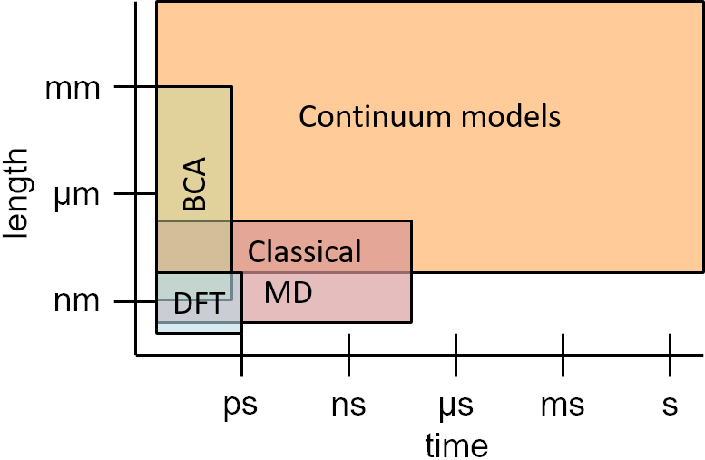
The BCA method, discussed in Section III.1, describes the ballistic phase of the slowing down of the ions and of the development of collision cascades. Since the ballistic phase is over in less than a picosecond, application of the BCA method makes sense only on a sub-ps time scale. Ab-initio methods, in practice mostly DFT, are the most accurate techniques, but are restricted to picosecond and nanometer ranges because of their computational cost. Classical MD may be used for system dimensions of roughly up to \qty100ns and \qty100nm. These methods are described in Section III.2. Longer time scales are accessible by the kinetic Monte Carlo (kMC) method (Section III.3), which describes the evolution of a system given the probabilities of events. The actual limits of kMC are determined by the event frequencies and the density of objects in the system to be studied. Finally, continuum models (Section III.4) usually study systems beyond the single digit nanometer range, as they do not resolve materials on the atomic level.
In the following subsections, a concise review of the available computational techniques, with examples of their use, is presented. It is hoped that this overview provides a clear picture of the opportunities simulation provides for FIB processing.
III.1 Simulation techniques based on the binary collision approximation (BCA)
The BCA approach is the most widely used method to assess the scattering and slowing of energetic ions in matter and the effects of the associated collision cascades, i.e. sputtering, atomic mixing, and the formation of point defect damage. The motion of each energetic atom is described as a sequence of asymptotic trajectories between binary collisions with target atoms that are at rest before the collision. Detailed information on the associated algorithms is provided in the book by Eckstein [249].
III.1.1 Principles and limitations
The binary collisions are normally treated as elastic with repulsive-only screened Coulomb interaction potentials, as e.g. in the “universal”[250] or “Kr-C”[251] parametrization. Energy transfer to the target electrons is included either nonlocally along the free paths between the collisions, (e.g. using a universal analytical description [252] or specific semiempirical data [253]), or locally dependent on the collisional impact parameter [254], or as a combination of both.
Simulations based on the BCA method are often denoted as Monte Carlo (MC) simulations due to the random choice of collisional parameters, such as the impact parameter and the azimuthal position of the target atoms relative to the trajectory of the moving atom. In random and amorphous media, this applies to all binary collisions during the simulation. In contrast, in crystalline media only the initial position of the incident projectile relative to the lattice atoms is treated randomly, while the subsequent slowing down, including the generation and termination of a collision cascade, is largely deterministic due to the positions of the lattice atoms being fixed except for thermal vibrations.
A prominent advantage of BCA simulations is their low computational cost and very fast performance, which allows modeling even of large systems up to the macroscale and the treatment of incident ion energies up to the MeV regime. However, in contrast to MD simulations (see Sect. III.2), the BCA model fails if a significant fraction of the collisions occurs between moving atoms. Such so-called “collisional spikes” or “elastic thermal spikes” [255] form in dense cascades generated under heavy-ion bombardment in the energy regime centered around the maximum of the nuclear stopping force [256] (typically around \qty100keV). However, any collision cascade also dissipates into a collisional spike before its final thermalization, which sets a low-energy limit on the validity of the BCA. Depending on the material, estimates [249] and comparisons with molecular dynamics simulations [257, 258] indicate a failure at energies below several tens of eV. However, experience shows that sputtering, which is dominated by cascade atom energies slightly above the surface binding energies of \qtyrange28eV [256], is rather well described [259, 260]. This suggests a practical lower energy limit of validity. Undoubtedly, BCA breaks down below the bulk binding energy of typically a few eV, where the purely repulsive interaction potential is no longer appropriate and many-body interaction has to be taken into account. This excludes e.g. the derivation of local atomic configurations after thermalization.
It must also be noted that BCA simulations require predefinition of a number of options and parameters, such as the choice of interaction potential, the addition of ‘soft’ collisions with more distant target atoms, the type of electronic interaction, and the surface binding and atomic relocation threshold energies, which are often difficult to identify and unavailable in the literature, particularly for compounds 222Note that except for the electronic interaction, these predefinitions are unnecessary in MD simulations because proper choice of the interaction potential ideally covers all bulk and surface interactions down to thermal energies.. Whereas ion ranges derived from BCA simulations are mostly reliable within , sputtering and defect results are significantly influenced by these preselections. As a result of parameter variations within physically sound limits, calculated sputtering yields may easily change by more than 50% [261]. For the different BCA codes, parameters are often not chosen from theoretical or experimental information, but justified based on prior experience comparing the simulation results to experimental data.
Originally, BCA codes were designed for “static” simulations during which the system is assumed not to be altered by the irradiation. This allows the prediction of range and damage distributions as well as sputtering yields with high statistical precision when a sufficiently large number of incident projectiles is employed. In the simulation of ion implantation into single-crystalline targets, “dynamic” consideration of damage buildup is required if the fluence exceeds a certain threshold,[262, 263] as crystal damage reduces or suppresses channeling. This is achieved by choosing collision partners randomly instead of from the crystal lattice, with a probability proportional to the damage. More often, the term “dynamic BCA simulation” refers to the modification of the chemical composition and geometry of the target, which occurs experimentally for a sufficiently large number of incident ions. Specific BCA codes track implanted ions as well as relocated and sputtered recoil atoms in order to continuously update the local composition in multicomponent systems and the surface position or the surface contour in 1D or 2D/3D systems, respectively. Simultaneously, the composition-dependent local atomic density must be updated by volume relaxation and/or material transport 333Again, this dynamic modification is straightforward in MD simulations, but in systems exceeding the nanoscale and for higher ion energies it is often impeded by excessive computational cost..
III.1.2 Specific BCA codes
Among the large variety of BCA-based simulation codes that have been described in the literature, we will in the following only address a few selected ones, in particular those that are presently in broader use and/or offer new features with respect to nanosystems, specifically for FIB applications. For a rough classification, see Table 3; access information for most of the codes can be found in Ref. 264.
| Code | Geometry | Atomic | Surface | Dynamic |
| structure | relaxation | |||
| TRIM[253, 265, 266] | 1D | amorphous | planar | — |
| TRIDYN[267, 268] | 1D | amorphous | planar | 1D |
| SDTrimSP[269] | 1D | amorphous | planar | 1D |
| IMINTDYN[270] | 1D | amorphous | planar | 1D |
| Crystal-TRIM[271, 262] | 1D | crystalline | planar | — |
| IMSIL[263, 272, 273, 274] | 1D/2D | amorph./cryst. | polygons/pixeled (adjusted) | –/1D/2D |
| SDTrimSP-2D[275] | 2D | amorphous | pixeled | 2D |
| CORTEO[276, 277] | 3D | amorphous | voxeled | — |
| TRI3DST[278] | 3D | amorphous | analytical | — |
| IRADINA[279] | 3D | amorphous | voxeled | — |
| IM3D[280] | 3D | amorphous | analytical/triangularized | — |
| SDTrimSP-3D[281] | 3D | amorphous | voxeled | 2D |
| TRI3DYN[282, 283, 284] | 3D | amorphous | voxeled (planarized) | 3D |
| EnvizION[285, 286, 287, 288, 289, 290, 291] | 3D | amorphous | voxeled | 3D, near-surface |
TRIM [265, 266] has been the most widely used BCA code for several decades. It offers a very convenient graphical user interface [253] for fast generation of range and damage statistics, and rough estimates of sputtering yields in amorphous semi-infinite or thin-film systems with a flat surface. The restriction to amorphous media is often not a severe limitation, since many materials become highly damaged or even amorphized under irradiation and, depending on the conditions, most ion or recoil atom trajectories are random in nature, even in crystalline materials. TRIM partly fails in details, such as for sputtered atom angular/energy distributions [292].
Sometimes the crystal structure of the irradiated material does matter. Typical cases include low-fluence or single-ion implantation aligned with a low-index crystallographic direction [293] and the sputtering of elemental metals [260]. Codes that consider the crystal structure are Crystal-TRIM [271, 262], which is restricted to certain materials, and IMSIL [263, 272, 273, 274], which allows more general crystal systems and sputtering simulations.
Based on the early TRIM sputtering version TRIM.SP [261], 1D dynamic relaxation has been implemented in TRIDYN [267, 268] and in SDTrimSP [269]. In connection with the recent broad interest in nanostructures, BCA codes have been extended to treat 2D and 3D systems using pixel and voxel grids, respectively. For static operation only, the surface for simple bodies may be defined analytically, such as in TRI3DST [278] and IM3D [280], or triangularized as in a second option of IM3D. With a pure voxel approach, the stepped surface contour resulting from pixel or voxel grids may cause artifacts by e.g. capturing atoms at glancing incidence (which could in fact occur experimentally). This may be overcome by a local adjustment of the near-surface nodes [274] (IMSIL), or by local planarization of the surface [284] (TRI3DYN). In IMSIL for 2D dynamic simulation [273], pixels that are affected by collisional transport become distorted based on an algorithm which optimizes their volumes, and are subsequently projected onto the original pixel grid. In contrast, SDTrimSP-2D [275] relaxes the pixel volumes along one dimension only toward a specified surface. 3D dynamic simulations have been demonstrated using TRI3DYN [282, 283, 284] and EnvizION [285, 286, 287, 288, 289, 290, 291]. For overall volume and surface relaxation, TRI3DYN makes use of material exchange with nearby voxels or the surface, whereas in EnvizION the relaxation is limited to near-surface regimes. TRI3DYN even works for macroscopic systems, while EnvizION is limited to the nanoscale, since each voxel contains only one atom. A characteristic result of a TRI3DYN simulation is presented in Fig. 6, demonstrating surface erosion and contamination during irradiation of a Au nanosphere on a Si surface.

III.1.3 BCA-based simulations of FIB processing
1D static BCA simulations have often been employed for understanding experimental findings in FIB processing, such as in recent studies of FIBID [294, 295, 296, 297]. These have also been used to generate, e.g. angle-dependent sputtering yields and angle-energy distributions of sputtered atoms to describe erosion and re-deposition, respectively, in 2D and 3D “level set” [298] or “segment based” [299, 300, 301] simulation models of the surface contour development during FIB induced erosion, see Section III.4.
A direct 2D dynamic BCA simulation of FIB induced erosion is described in Ref. 273, where the milling of trenches is exemplified. The results shown in Fig. 7 demonstrate the slowing of the milling process by atoms sputtered from the bottom and redeposited to the sidewalls.

In addition, a high concentration of implanted atoms at the bottom of the trench emerges, which pushes material upward along the trench sidewalls via volume relaxation. The simulation of the milling of a slit in a membrane is described in Ref. 274.
With particular focus on FIB processing, Rack and coworkers have published a series of 3D dynamic results obtained with EnvizION[285, 286, 287, 288, 289, 290, 291]. In addition to the collisional BCA simulation and relaxation algorithms used, simplified models have been implemented for reactive-gas assisted erosion and deposition, including secondary-electron mechanisms [160]. Selected results have recently been reviewed in Ref. 302. For an introduction to gas-assisted processes, see also Section III.4.2.
Dynamic BCA simulations may also be employed to characterize specific FIB based nanoanalytical methods. An example is a 1D TRIDYN simulation of damage buildup during FIB milling of nanomembranes for TEM analysis [303]. Another example is the 3D TRI3DYN simulation of STIM in a HIM device, as shown in Fig. 8.

Simulations such as those presented in Fig. 8(a) help to identify the detector geometry for optimum image contrast and resolution. Furthermore, Fig. 8(b) indicates that there is only minor degradation of the sample by surface sputtering and recoil atom transport between the core and the shell, and between the sphere and the substrate.
III.2 \Acl*md and molecular statics
Although BCA methods are able to provide insights into processes developing during the ballistic (sub-ps) phase of ion irradiation, they cannot predict details of the permanent modification of the target’s atomic structure, such as defect clusters or dislocations including their strain fields. Particularly with heavy ions, heat spikes may develop even in keV energy cascades, and the local melting of the target affects the amount of damage formation and atomic mixing [304]. The accuracy of the BCA approach diminishes [257, 258] at energies roughly below \qty100eV and it completely fails in the low single-digit eV energy range. Hence, \Acmd is often the method of choice for the simulation of phenomena associated with atomic motion at eV and sub-eV kinetic energies.
III.2.1 Principles and simulation codes
Most approaches in practical use are based on the Born-Oppenheimer approximation, which assumes that the electronic subsystem relaxes instantaneously to its ground state at any time as the atomic nuclei change their positions. Consequently, the effect of the electrons can be embodied in a potential energy function that depends only on the nuclear positions [305]. Analysis of this energy function allows determination of many material properties as well as the time evolution of the system, e.g. in an irradiation experiment. This is even true when deposition of energy into electronic degrees of freedom dominates, such as for 30 keV He ions impinging on Au clusters [306] where defect production is still governed by ballistic energy transfer as excitations are quickly delocalized.
In the MD method, Newton’s equations of motion are solved for all atoms in the system, using forces calculated from the potential energy function [307, 308, 305]. This is done iteratively with time steps on the order of \qty1fs, with the time step being dependent on the ion/atom velocities and their masses. At the end of the simulation, when the energy is equilibrated everywhere in the system, the final structure can be analyzed. Due to the short time step required, total simulation times are limited to the nanosecond or at most microsecond range for classical MD and to picosecond for ab-initio MD. Effects corresponding to longer timescales are sometimes mimicked by increasing the temperature in the system, which then allows observation of annealing (recombination) of defects and the relaxation of strain [309]. Detailed descriptions of the principles of these MD methods can be found in Refs. 247, 310.
ms methods are concerned with finding minima and saddle points in the potential energy function. The former identify (meta-)stable atomic configurations, while the latter allow the determination of energy barriers for diffusion and chemical reactions. Finding global minima, corresponding to stable as opposed to metastable configurations, can be tricky. Various methods have been developed, see Ref. 305 for details.
Simulation codes can be classified into classical and ab-initio codes. In the first group, the potential energy and forces are calculated by evaluating mathematical expressions with empirical parameters, while in the second group, they are determined by solving approximations to the Schrödinger equation. The most widely used classical MD code is LAMMPS [311, 312]. Another general purpose MD code is DL_POLY [313]. Codes specifically designed for the simulation of radiation effects include PARCAS [314], DYMOCA [315], and MOLDYCASC [316]. GROMACS [317] and NAMD[318] mainly target biomolecular systems. Popular ab-initio codes capable of performing MD simulations are VASP[319] and QUANTUM ESPRESSO[320].
III.2.2 Models for the potential energy function
Among the ab-initio methods, DFT [321] with local and semilocal exchange-correlation (XC) functionals provides a good compromise between accuracy and computational expense for the calculation of the potential energy function. Some phenomena such as van der Waals interactions, magnetism (especially when spin-orbit coupling is taken into account), or accurate evaluation of the bandgap in semiconductors, require one to go beyond “vanilla” DFT by either using more sophisticated XC functionals [322] or post-DFT methods, such as GW/RPA (many body perturbation theory / random phase approximation) [323]. But otherwise, DFT simulations normally provide reliable results with respect to the atomic coordinates and energetics on the scales relevant for the modeling of ion irradiation effects. \Acdft is capable of predicting charge states of defects and static charge transfer [324], while time-dependent (TDDFT) can describe charge transfer dynamics in ion collisions. The advantage of ab-initio simulations is that they do not require any material-dependent parameters from the user. The disadvantage is their high computational cost, which scales as , where denotes the number of valence electrons or atoms in the simulation. This imposes a practical limit on the system size that can be handled by DFT, which using supercomputers is currently on the order of 1000 atoms.
If larger systems need to be handled, empirical interatomic potentials (sometimes called force fields) must be used to describe the potential energy function. The computational expense of these simulations scales nearly linearly with the number of atoms. On the downside, the mathematical expressions describing the interatomic potentials are only approximations of the true potential energy function, and the parameters in these models must be fitted for each combination of chemical elements in order to reproduce the physical properties of the material (e.g. lattice parameters, elastic properties, bond energies, energetics of defects, stability of sputtered fragments, etc.). Care is needed if the simulation results in atomic arrangements that are outside the range of atomic arrangements used for the fit. Moreover, the availability of force field parameters can be a limiting factor when looking for new applications, since the development of new parameter sets is a tedious task [325]. To overcome this bottleneck, various methods have been developed in recent years [326, 327, 328, 329, 330, 331, 332, 333].
Collections of 1000+ interatomic potentials together with their parameters for individual systems are available in the NIST Interatomic Potentials Repository [334] and the Knowledgebase of Interatomic Models (OpenKIM) [335]. Educated choice of an appropriate interatomic potential is essential for the success of a simulation. In Table 4, the most popular options are listed together with the types of atomic interactions they can describe and their computational expense.
| Interatomic potential | Type of | Execution |
| interaction | time | |
| Lennard-Jones[338] | van der Waals | 1 |
| EAM[339] | metallic | 1.8 |
| Stillinger-Weber[340] | covalent | 3.4 |
| Tersoff[341] | covalent | 4.4 |
| Coulomb-Buckingham [342] | ionic | 4.7 |
| CHARMM[343] | biomolecules | 14.1 |
| MEAM[344] | metallic/covalent | 16.5 |
| COMB[345] | chem. reactions | 188 |
| ReaxFF[346] | chem. reactions | 197 |
| Kieffer[347] | chem. reactions | — |
| machine learning (ML) | all | 10–10000 |
| DFT | all |
All but the CHARMM force field, which is mainly used to describe biochemical molecules such as proteins, lipids and nucleic acids, allow for bond breaking, a prerequisite for the simulation of almost all irradiation effects. For an introductory text on interatomic potentials, see Ref. 305.
Overall fitting of a single functional form with a limited number of parameters to reproduce a vast range of material properties has frequently proven to be an unmanageable task. To overcome this limitation, machine learning (ML) potentials have recently been developed [348, 349]. Common to all flavors of ML potential is their description of the potential energy using multiparameter functions of the local environment around each atom. To determine the parameters, a large data set of potential energies and corresponding interatomic forces for a specific set of chemical elements in different configurations is generated by DFT calculations. Hence, the flexibility of these potentials is much greater than that obtained using empirical interatomic potentials, and if carefully developed, they are able to provide results with an accuracy comparable to DFT. There have also been attempts to train ML potentials on-the-fly to handle situations that had not originally been anticipated, such as large surface reconstructions or rare chemical events [350, 351].
As an example, Fig. 9(a) demonstrates the ability of the Gaussian approximation potential (GAP) [352] to reproduce the DFT results for the cohesive energy of pure W as a function of atomic volume in different phases [353]. Similar agreement between predictions of the tabGAP potential (a more efficient version of GAP [354]) and the DFT calculations of mixing energies and bulk moduli is shown in Fig. 9(b) for multiple combinations of binary, ternary and quaternary alloys.
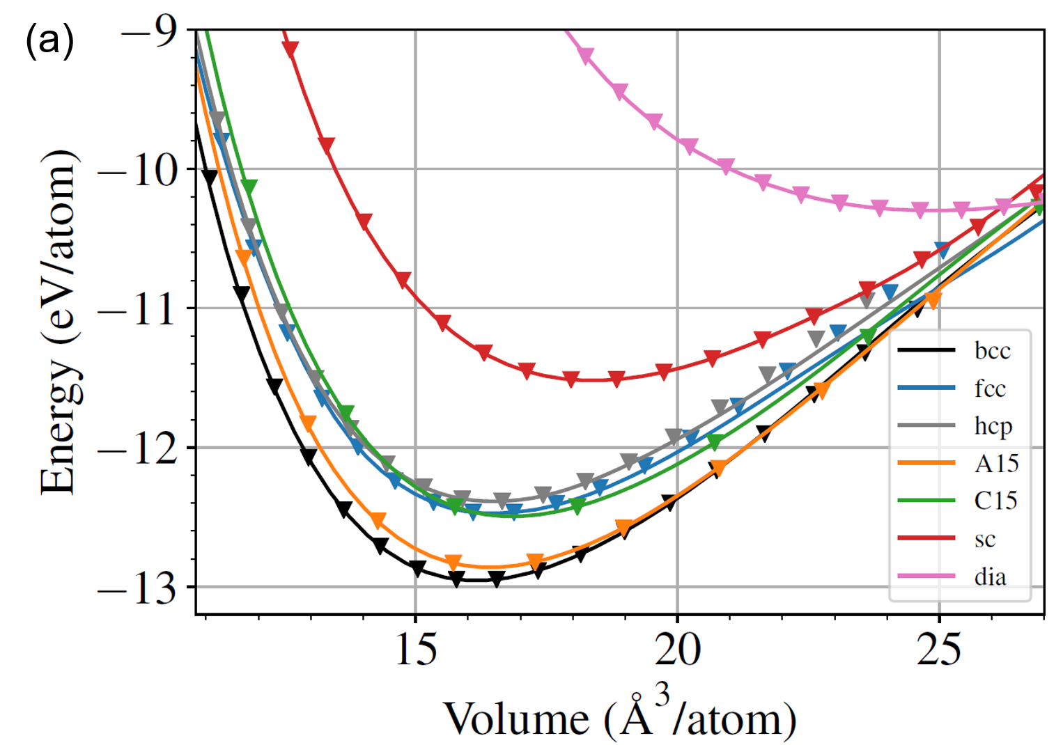

The interatomic potentials discussed so far describe the potential energy function near equilibrium or a few eV above equilibrium. During irradiation simulations, much higher potential energies occur in close collisions. In this regime, purely repulsive potentials such as also used in BCA simulations, e.g. the universal Ziegler-Biersack-Littmark (ZBL) potential [355] or the potential obtained with the all-electron DFT code DMol [356], provide accurate results. These potentials need to be smoothly joined with the material-specific empirical potential at small distances [357]. For ML potentials, it is advantageous to already include the repulsive potential in the training phase [353].
III.2.3 Applications of molecular dynamics to FIB irradiation
Large-scale MD simulations have been employed to gain insight into nanostructure formation and the modification of nanostructures. Das, Freund, and Johnson [358] investigated the Ga FIB-induced formation of nanopores in Si membranes, which are of interest for biological applications. They identified a local boiling mechanism that could be explosive at high enough ion fluxes [358]. Moreover, they found recirculating material flow, which they explained as being driven by temperature-gradient induced surface tension gradients [359]. Another interesting phenomenon occurs during ion irradiation of Si nanopillars. At room temperature, the pillars shorten (Fig. 10a), while at elevated temperature, they become thinner (Fig. 10c).

In the MD simulation performed at room temperature (Fig. 10b) the Si amorphizes, which initiates viscous flow due to the ion hammering effect [360] resulting in a shortening of the nanopillar as seen in the experiment. In contrast, in the BCA simulations shown in Fig. 10d, the nanopillar mainly shrinks in diameter, in agreement with the experimental results at elevated temperature. This is explained by the neglect of viscous flow in the BCA simulations, which in fact does not occur when the target remains crystalline at the higher temperature. As a third example, MD simulations have examined how a balance between beam spreading, erosion and defect-induced strain limits the thinning of FIB lamellae [362].
Chemical effects in sputtering cannot be described by BCA simulations, but can be using MD simulations employing reactive force fields. For instance, the sputtering of Si by low-energy O and Si ions using the Kieffer force field [347] showed that two mechanisms are mainly responsible for sputtering: (i) emission of atoms forming clusters a few Angstroms above the surface, and (ii) ejection of clusters that are loosely bound to the surface [363]. As another example, the impact of residual water molecules on sputter yields of Si bombarded with Ar has been studied (cf. Fig. 11).
Here, MD simulations using the ReaxFF potential optimized for the Si-C-O-H system [364] are compared to SDTrimSP BCA simulations. For the MD simulations, a much weaker dependence of the O and H partial sputter yields on the incidence angle is found. The difference might be explained by the random positions of the H and O atoms in the SDTrimSP simulations, presenting more efficient scattering centers than the more regular atomic configurations in the MD simulations at incidence angles between about 50° and 80°. At angles closer to perpendicular and grazing incidence, the MD results show higher sputter yields than BCA. This may be explained by the desorption of water molecules, which is not included in the BCA model. Note that the maximum Si sputtering yield is found at around 65°, whereas the maxima for H and O are found between 70° and 80°. As a practical conclusion, when the mixing of contaminants into the sample should be minimized, angles closer to grazing incidence should be favored.
Defect formation in all kinds of materials has been a traditional application field for MD simulations [247]. Although much insight has been gained, quantitative and sometimes also qualitative results are in doubt, due to the inaccuracies of empirical interatomic potentials. For instance, the threshold displacement energy, the essential parameter for damage calculations in the BCA method, turned out to be substantially different for Si when calculated by DFT-MD compared to using the Tersoff or Stillinger-Weber interatomic potentials [365]. On the other hand, when using a ML potential, essentially the same values were obtained as with DFT [366]. Likewise, sputter yields for low-energy Ar irradiation of Si obtained with the ML potential were found to be close to experimental values, while the empirical interatomic potentials largely underestimate the yields [366]. Moreover, it was shown that damage buildup in keV energy cascades is strongly overestimated by the empirical potentials (see Fig. 12).

MD simulations have also provided good understanding of ion induced defect formation in free-standing [367, 368, 369] and supported [370, 371, 372] 2D materials, which is of interest for developing ultrathin membranes to encapsulate gases and other volatile systems for ion beam analysis [373], and also for the development of nanoporous membranes for advanced nanofiltration applications. As with bulk materials, new insight is gained for 2D materials using DFT-MD [374, 375, 376]. As an example, in the study by Kretschmer et al. [376] the importance of accounting for chemical interactions when evaluating the threshold displacement energy in graphene and hexagonal boron nitride (hBN) has been demonstrated.
III.2.4 Limitations and extensions
While in the BCA method, trajectories are only followed for atoms with energies exceeding a few eV, MD simulates all atoms in a region encompassing the collision cascade. Therefore, MD simulations are much more computationally demanding than BCA simulations. Taking into account that actual FIB processes often use rather high fluences, it is clear that the computational cost of this may be a challenge. Moreover, due to the limitation of the MD time step to values that resolve lattice vibrations, the time between collision cascades cannot be fully simulated. Thermally activated events occurring during these time spans may be covered by kMC simulations as needed (see Section III.3). Often, however, such thermally activated events are neglected, and in addition, the system is artificially quenched to ambient temperature at the end of each cascade in order to shorten the time required to dissipate the energy deposited by the collision cascade [363]. This comes at the risk of possibly missing some relevant defect annealing.
The limitations of empirical interatomic potentials have already been discussed above. Another drawback of Born-Oppenheimer MD is the absence of an inherent description of electrons in the system. Electronic stopping can be included in MD as a frictional force [307], and the same stopping powers may be used as in BCA simulations. Modeling of electronic stopping of channeled ions, however, cannot be directly transferred from BCA to MD. Here, attempts have been carried out on a more sophisticated level [377, 378]. In addition, there is uncertainty about the low-energy limit to electronic stopping, which has been shown to be relevant for predicting sputter yields [379] and damage formation [380]. A related problem is electron-phonon coupling, which describes the exchange of energy between the electronic and ionic subsystems. Electron-phonon coupling may be included in MD simulations by the so-called two-temperature model [381]. However, so far no general consensus on the model for electron-phonon coupling nor its significance at FIB-relevant energies has been reached [382]. Recent insights from TDDFT [383] show promise for enabling a physically motivated parametrization of how electronic stopping and electron-phonon coupling relate to one another [384, 385, 386]. Other possible effects to consider include the modification of atomic interactions due to electron excitations in the system [387].
Born-Oppenheimer MD also fails to describe e.g. the transitions between electronic states or the neutralization of ions in the vicinity of a 2D target. These situations may be treated by TDDFT-MD (Ehrenfest dynamics). In irradiation simulations using Ehrenfest dynamics, the nuclei are usually approximated as classical particles moving in the time-dependent average potential of the electrons, while the electron subsystem evolves according to TDDFT. Due to their complexity and high computational cost, Ehrenfest dynamics simulations using massively parallel computers are currently only feasible for systems comprising tens of atoms and for times up to picoseconds. The method has been successfully applied to electronic stopping power calculation in various targets [388, 389, 390, 391], excitation mediated diffusion modeling [392], and simulations of the behavior of inorganic 2D materials under electron beam irradiation [393], but its applicability is limited by the mean-field approximation and the resulting propagation of mixed states. For example, the sputtered atoms may have fractional charges that are unphysical. It is also worth noting that this approach has been demonstrated to work for describing the formation of HIM images by assessing the spatial distribution of excited electrons immediately after the ion impact [394].
III.3 \Acf*kmc
The time scale accessible by MD simulations is in the nanosecond range, which is sufficient for the system to reach thermal equilibrium after an ion impact. After this time, diffusion and interaction of defects take place by thermally activated events. Examples of such events are diffusion hops, attachment of an atom to a cluster, or recombination of two defects. The rate constant of each event may be determined by transition state theory using the potential energy function of the system, e.g. using DFT and the nudged elastic band (NEB) method [395]. Sometimes, this parametrization can be achieved directly from experimental data, e.g. by fitting to a known temperature-dependent diffusion coefficient. kMC is a method that evolves systems described by such events stochastically. For a basic introduction to the method see Ref. 396. Another review is found in Ref. 397, and more recent ones with special emphasis on radiation effects and semiconductor processing can be found in Refs. 398 and 399, respectively. Other approaches for extending the time scale of MD are discussed in Ref. 400.
Several variants of the kMC method have been developed. On-the-fly kMC determines energy barriers of possible events during the course of a simulation. This technique has been used to simulate defect diffusion in Fe [401], defect evolution in graphite [402] as well as deposition and sputtering [403]. On-the-fly kMC can easily be combined with MD, since both methods can use the same potential energy function, and neither needs prior knowledge of possible events. However, the search for possible events makes the on-the-fly variant of kMC the most computationally expensive.
Setting up a catalogue of events a priori can be approached in two ways. In lattice (or atomistic) kMC, a lattice is defined where each site can be empty or occupied by an atom. Events are hops from one lattice site to another with rates modeled based on the local environment of each site. Use cases include vacancy diffusion [404], solid-phase epitaxial regrowth [405, 406], sponge structure formation in Ge [407], self-organized surface pattern formation [408], knock-on damage in hBN [409], and phase decomposition of substoichiometric SiO2 into Si nanoclusters in an amorphous SiO2 matrix [410].
In object kMC, in addition to vacancies and impurity atoms, other defects including clusters are treated as individual objects that are tracked as they move and/or react with each other. The atoms of the “background” material are not explicitly represented. Therefore, the system size accessible by object kMC is determined by the number of objects in the simulation, rather than by some fixed volume. The object kMC approach has mainly been used in simulations of radiation effects in nuclear materials [411] and semiconductor processing [399, 412].
Lattice and object kMC can be combined not only with MD [402, 403, 408, 411], but also with BCA [404, 410, 411, 412]. In addition, kMC schemes are occasionally also used to describe system evolution due to non-thermally activated events. For instance, in Ref. 373 the accumulation of defects in a graphene sheet is modeled based on defect production probabilities obtained by MD simulations of ion impacts.
III.4 Continuum modeling
Unlike the methods described in the previous subsections, continuum models do not use individual atoms as the objects of simulation, but instead use quantities that are continuous functions of space and time. For example, in a continuum approach the ion beam is described by its spatially dependent flux (number of ions per area and time increment), the adsorbed precursor molecules are described by their concentration (number of molecules per surface area), and the boundaries of solids are described by mathematical surfaces.
III.4.1 Ion implantation and milling
In the absence of ion beam mixing and other secondary effects, the distribution of implanted ions may be obtained by the convolution of the beam flux and a “point response” . The point response is the probability density function for the stop position of an ion entering a planar target at the origin of the coordinate system. For the purpose of this discussion, we assume the ions to be incident along the negative axis; and denote the other two Cartesian coordinates. If the surface is described by a height function , the increase in the concentration of implanted atoms with time is given by [413]
| (2) |
For practical reasons, is often approximated by a Gaussian function whose parameters can be determined by a BCA simulation. For an unscanned beam, the beam flux is constant in time, for a digitally scanned beam it is piecewise constant, and for an analog scanned beam it is a continuous function of time.
Displaced atom and deposited energy distributions can be calculated in a similar way. They may be of interest for estimating the damage to the target, and as input for solving the heat transport equation, respectively.
Sputtering causes the surface to recede. The resulting surface velocity in the direction of the surface normal is given by
| (3) |
where denotes the atomic volume of the target atoms, and the flux of atoms through the surface element around the point under consideration. In the absence of secondary effects, is given by the flux of sputtered atoms, , with the local incidence angle of the ions and the sputter yield. The sputter yield may be determined by BCA simulations or experiment.
As long as an initially flat surface, , develops only small slopes, the surface contour reflects the beam profile:
| (4) |
Once larger slopes occur, further prediction of the target topography usually requires iteration [414] or more refined numerical techniques. One option is to move surface marker points along the surface normals [415]. The drawback of this method is that as the nodes move, they tend to form loops which have to be removed. A simple technique to avoid loops, which works for surfaces that remain as height functions throughout the simulation (i.e. the surface has no overhanging structures), is to interpolate the surface back to an grid after each time step [416]. More general solutions are cell-based and level-set methods. The former represent the target by filled or partially filled voxels, while the latter describe the surface as the zero level-set of a distance function and solve a differential equation for this quantity [415]. Implementations of the marker and level-set methods for FIB milling have been presented in Refs. 417, 418, 419, 420, 421, 422 and Refs. 298, 423, 424, 425, 426, respectively.
When the surface develops larger slopes, two additional effects come into play (see Fig. 13). First, sputtered atoms may be redeposited on other regions of the surface (dark blue arrow).
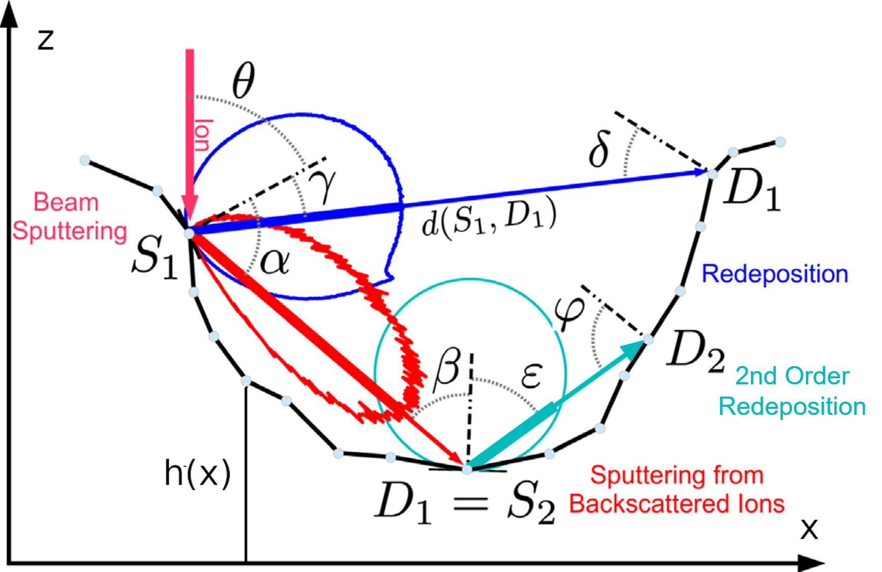
Second, ions may be backscattered from their primary incidence point and impact the target somewhere else (red arrow), where they cause sputtering. The secondary sputtered atoms may then be redeposited (light blue arrow). These processes add significantly to the complexity of the simulation: The angular (and possibly energy) distributions of the sputtered and backscattered atoms (blue and red elliptical lines, respectively) have to be described in some way, and the computation of the fluxes at each marker point (D1 and D2) requires the summation over the contributions of all other marker points (S1 and S2) [421, 422, 232]. This summation may be substituted by randomly starting individual rays at the source points, which adds a MC aspect to the simulation [423, 427]. In contrast to a BCA simulation, however, the atom trajectories are not followed within the target, but their exit characteristics are chosen according to precalculated angular (and energy) distributions. Either way, redeposition and backscattering add contributions to the flux of Eq. (3). The same applies to contributions from etching and deposition in the case of gas-assisted processes (see Section III.4.2).
In principle, many physical and chemical effects may be considered in a continuum approach. However, when a new ion-material combination is considered, each model requires input from more fundamental simulations or experiments. This may be straightforward for the parameters of the most basic models, such as the mean values and standard deviations of implanted ions or the sputter yields. However, as the model complexity increases, parameter determination becomes more cumbersome.
Our discussion so far has neglected dynamic changes to the target composition. As the irradiation proceeds and ions are implanted, however, the stopping power for the ions changes, and so does the point response in Eq. 2. The same applies to sputter yields and angular distributions. Consideration of dynamic effects would also require modeling of atomic mixing. This has not been attempted so far in a multidimensional continuum approach. Moreover, sputtering is a nonlocal effect, i.e. the sputtered atoms are not emitted exactly at the impact point of the ion, which may be important in nanofabrication. In addition, ion implantation and atom relocation may cause topography changes through volume relaxation (cf. Section III.1). These effects are building blocks of the theory of spontaneous pattern formation [428], but have not been considered in continuum simulations of FIB processes so far.
Another effect that can be treated within a continuum approach is beam induced heating. Temperature distributions can be calculated by solving the heat transport equation with heat sources given by the energy deposition of the collision cascades, using finite element or finite difference methods [429, 430]. The estimates are important because elevated temperatures may reduce deposition rates in FIBID (see Section III.4.2) and may lead to heat damage in biological samples (see Section III.4.3).
III.4.2 Gas-assisted deposition and etching
Gas assistance enables selective 3D nanoprinting and enhanced etch rates in FIB processing. Continuum models attempt to quantify the local deposition or etch rate caused by the chemical surface reaction between the volatile adsorbates and the primary ions, their locally generated SEs, and excited surface atoms, as follows.
Deposition reaction:
(5)
Etch reactions:
(6a)
(6b)
FIBID typically employs volatile metalorganic compounds to deposit metal-containing nanostructures[431]. For focused ion beam induced etching (FIBIE), the adsorbed precursor needs to dissociate upon irradiation into a reactive species that removes atoms from the underlying substrate by forming a volatile compound, but does not leave traces of other dissociated precursor elements.
Present FIBID and FIBIE models treat the desorption of volatile fragments in reactions (5) and (6b) as instantaneous and assume that the etch reaction (6b) is fast compared to reaction (6a), see Ref. 432 for a review. Both processes share the same formalism to calculate the surface coverage (normalized concentration) of adsorbates, which is defined by the rate equation (in units of inverse time):
| (7) |
The terms and are adsorbate source terms describing gas and surface-diffusion transport, respectively, while the other two terms are adsorbate sink terms related to the rates of desorption and dissociation, and , respectively, as schematically depicted in Fig. 14. This approach could be extended to multiple chemical pathways, as in models developed for FEBID and focused electron beam induced etching (FEBIE) [433].

PIs, SEs, and ESAs are the co-reactants. The concentration of impinging PIs is given by the ion beam spatial profile and the FIB exposure time. Energy and spatial distributions of SEs and ESAs result from the interaction of the PIs and the recoils with the etched substrate or growing deposit. must be determined from more fundamental simulations. For SEs, BCA simulations of PIs and recoils combined with MC simulations of electron transport [435] have been performed using a simple model for SE generation. More refined theories of SE generation also exist [436, 437, 438]. For ESAs, BCA simulations reach their low-energy limit of applicability, since atom energies of around 1 eV can already dissociate the precursors. An alternative for simulations of ESAs would be MD. Recently, first attempts of MD were undertaken for FEBID where atomistic detail on metal grain size, distribution, and composition in the deposited metal-carbon material could be obtained[439, 440]. The treatment of adsorbate dissociation by electrons relied on experimentally measured fragmentation mass spectra and fragment ion yields for structurally similar molecules, which needed smart appropriate scaling. Desorption of the adsorbate fragments was approached using an external force field. Both approaches limit the predictive power of the simulations at present, but show promise if appropriately refined in the future. Modeling of FIBID would require inclusion of the ESA and milling mechanisms into the simulation.
Finally, the chemical fluxes of deposition or etching (in units of atoms per area per time) are proportional to the dissociation rate and the coverage of adsorbates as shown
| (8) |
where denotes the number of atoms deposited or etched per dissociated precursor molecule and is the number of adsorbate sites per unit surface area. Note that the product defines the rate of deposition or etching for a single site in units of inverse time. The flux according to Eq. (8) must be added to the flux of sputtered and redeposited atoms discussed in Section III.4.1.
Modeling of the four terms on the right-hand side of Eq. (7) is key to the successful simulation of FIBID and FIBIE. The first term represents a widely used pragmatic simulation approach. It assumes non-dissociative Langmuir adsorption, which treats adsorption as physisorption with a maximum coverage of one monolayer of adsorbates. Other adsorption schemes include dissociative adsorption [441], multilayer adsorption [442], and chemisorption[443]. Open source MC codes are available for the calculation of the gas impingement rate on the irradiated area for a given geometrical arrangement of nozzle and substrate [433, 444, 445]. Typical values are in the range s-1.
The desorption rate , contained in the second term on the right-hand side of Eq. (7), is the inverse of the surface residence time. It depends exponentially on the temperature as well as on the type of adsorption occuring on the growing/etched surface being irradiated. The desorption rate can cover several orders of magnitude depending on the molecule-surface interaction.
The third term, the adsorbate dissociation by irradiation, is key for selective FIBID and FIBIE as it captures the crucial non-thermal irradiation-driven chemistry of the process. Different contributions involving PIs, SEs, and ESAs are involved in adsorbate dissociation, see Fig. 14. In principle, the dissociation rate can be calculated from the energy dependent dissociation cross section and the energy distribution of the SEs or ESAs via
| (9) |
describes the efficiency of reactions (5) and (6b) as functions of the energy of the PIs, SEs, and ESAs. Such energy dependent calculation is hampered by the fact that so far reliable only exist for electron induced dissociation reactions of molecules in the gas phase, see for example Ref. 446. A pragmatic approach assumes that such gas phase can be linearly scaled to the net deposition (etch) cross section (see below). This approach omits the quenching of certain dissociation channels (fragment production) due to the adsorbate state situation [432, 447, 448, 449]. Simulations will thus not be accurate with respect to deposit composition, but the deposit (etch hole) shape can probably be adequately modeled. The only established energy dependent cross section for deposition conditions exists for the molecule (CH3)3Pt-CpMe under electron irradiation [450], describing the observed dissociation of one volatile CH3 ligand from the adsorbed molecule leading to a deposit of atomic composition Pt:C=1:8.
So far, the ESA induced adsorbate dissociation reactions have not been studied, probably due to experimental issues in deconvolution of the naturally involved (secondary) electron contributions. Recent condensed phase studies using Ar-ion irradiation [451] point to the importance of the additional mechanical sputtering effect of the PIs, which can help remove more ligand fragments than SEs alone and thus achieve a higher metal content material. The elemental species, charge, and energy of the ions open up a wide field of fragmentation chemistry with metalorganic or “etch” adsorbates, which is still unexplored, particularly with respect to missing . Moreover, the energy distributions in Eq. (9) are not easily obtained in a continuum approach. Therefore, while using Eq. (9) with a MC approach for SE generation and transport is a promising approach, for the ESA mechanism one has to resort to simpler approaches, as is also often undertaken to describe the SE mechanism.
In a simpler approach, dissociation is generically modeled via the dissociation rate , where is the local flux of the PIs, and is the so-called net deposition or etching cross section, which is deduced from fitting the shape of the deposit or etch hole. Such cross sections do not distinguish between the different contributions of PIs, SEs, and ESAs, nor do they distinguish between the fragmentation reactions. The modeled shape or rate can sometimes retroactively be attributed to a certain mechanism, when the yield and/or spatial distribution of either PIs, SEs, or ESAs matches the deposit or etch hole dimensions. In this way, the ESA dissociation mechanism was identified to be dominant for FIBID using noble gas ions heavier than He [452, 434] and the SE dissociation mechanism was identified as important for He-FIBID nanopillar growth.[453] In those cases, may be interpreted as the flux of ESAs or SEs. Experimental net cross sections (yields) obtained from ion and electron induced deposition are available for a few precursor molecules [431], and deposit compositions upon electron irradiation were recently reviewed in Refs. 454, 441.
The fourth term in Eq. 7, the surface diffusion rate, is proportional to the surface diffusion coefficient and the second spatial derivative of the adsorbate coverage . Thus, it becomes largest for intense and finely focused ion beams and can result in the delivery of considerable amounts of adsorbates to non-irradiated surface areas. Increasing temperature increases the surface mobility of the adsorbates exponentially.
The generation of local heat during ion irradiation can be an important factor influencing the outcome of a deposition process. Thermal contributions can alter the nonthermal irradiative dissociation pathways and exponentially change the diffusion constant (mobility) and residence times of the adsorbates on the surface. As an example, thermal effects are thought to be responsible for the bending of lateral nanowires as they grow[455]. As mentioned in Section III.4.1, the temperature distribution needed as input for temperature dependent models of mobility and residence time can be obtained by numerically solving the heat transport equation.[429, 430]
III.4.3 Applications to FIB processing
Simulations of FIB milling may be used to investigate the influence of beam shape and scan strategy on the final topography of the target [417], and to better understand the milling process. For instance, Lindsey et al. [301] investigated microtrench formation in trench milling and clarified the roles of redeposition and backscattering. In practice, often the inverse problem of determining beam and scan parameters for a desired geometry must be solved. In the simplest case, for low aspect ratio structures, this can be achieved approximately by choosing the pixel dwell times proportional to the desired depth at the respective pixel positions [228]. For higher accuracy, a system of linear equations for the pixel dwell times must be solved in order to consider the effect of beam overlap [414, 456]. For higher aspect ratio structures, when redeposition and/or backscattering need to be considered, repeated numerical simulations of the milling process must be performed until convergence to the desired structure is achieved. In practice, such structures are fabricated by applying variable dwell times across the scan area in multiple passes. Here one can either choose to apply the same pattern in each pass [232], or define layers to be milled in each pass and determine individual dwell time profiles [229].
Finite element and finite difference simulations of heat transport have been performed by Wolff et al. [430], who used them to verify a simple model for the estimation of target heating. Schmied et al. [457] employed a similar numerical approach to find beam scanning strategies that minimize local thermal stress in soft matter.
Gas-assisted FIB processes have been treated in a continuum approach mostly to help identify in which regime the surface reactions (5) and (6a) take place, i.e. whether they are mass-transport-limited (adsorbate-limited), or reaction-rate limited (PI, ESA, and/or SE limited), or driven by desorption or surface diffusion. These regimes strongly influence shape fidelity, homogeneity, and resolution, all of which are of utmost importance for 3D nanoprinting/nanoetching approaches. A review of both time dependent and steady-state analytical solutions of Eqs. 7 and 8, using simplifying assumptions, is found in Ref. 432. This theoretical framework closely resembles the one used for gas-assisted focused electron beam processing (FEBID/FEBIE), with the exception of physical sputtering and redeposition. Hence, analytical solutions established for the analogue electron-based FIBID/FIBIE variants straightforwardly apply. These include expressions obtained for steady-state surface diffusion and flat-top focused beam profiles [458, 459], long freestanding rods [460], 1D time dependent solutions [461], and expressions for lateral resolution [462] and etch/deposition gas mixtures [463, 464]. Analytical solutions without surface diffusion can be used in the PI, ESA, SE limited processing regimes (no concentration gradient of adsorbates due to high supply from the gas phase), or approximately when adsorbates cannot diffuse into the center of the FIB spot profile due their deposition at the perimeter. These conditions translate into very small FIB current and exposure (dwell) time [465]. Without the surface diffusion term, analytical solutions are more easily derived and thus cover a broader range of adsorbate-related dissociation mechanisms. These include the resulting deposit composition upon injection of two precursor species [466], multistep reactions involved in gas enhanced etching [433, 467], and experimental parameter maps [442].
Full numerical continuum simulations of a FIBID process using Eqs. (7) and (8) have been performed by Ebm et al.,[300] see Fig. 15.

In these simulations, an ESA-based model was used, assuming the concentration of ESAs to be proportional to the flux of sputtered atoms. The authors considered the nonlocal nature of sputtering, a prerequisite for obtaining parallel sidewalls in the lower part of the structure and the flying roof in the upper part. Simulations of pillar growth using voxel grids has been reported in Ref. 468.
Presently, simulations of FIBID/FIBIE are more advanced in the BCA-based approaches (cf. Section III.1.3). One reason for this might be that pure continuum approaches require the modeling of the SE/ESA intensities as an additional step. Also, BCA-based approaches include several collision cascade related effects, which cannot easily be modeled in a continuum approach (see Section III.4.1). On the other hand, uncertainties in some of the assumptions of both the BCA and the continuum approaches might be more significant in practice. These include the manner in which the energy and spatial distributions of the ESAs and SEs are determined, and assumptions about the fragmentation paths. Further development of either approach holds promise for model-assisted 3D nanoprinting, which has already been demonstrated for FEBID[469, 470] and has been started for FIBID[455, 287, 291].
IV Applications of focused ion beams
The various processes that are triggered when a beam of ions interacts with a sample form the basis of the multitude of FIB applications that are routinely used today. Accordingly, this section is intended to provide a comprehensive overview of this wide variety of experimental applications and is structured according to the different FIB processing techniques involved (see Fig. 16 for an overview).
In the following paragraphs, the breadth of FIB techniques is briefly outlined, to be highlighted in more detail in the subsequent subsections. Further reviews of these topics can be found in a number of recent articles [302, 471, 472, 43, 7].
Subtractive FIB processing:
Local material removal by a focused ion beam is based on physical sputtering. The incident projectiles knock out substrate atoms by momentum transfer, but also penetrate the material in a collision cascade. While the ejection of atoms is desired here, all other interactions with the substrate can cause unwanted side effects, such as amorphization, mixing, doping, dealloying, and others. Conventional Ga-FIB tools provide spatial resolution and sputtering yields high enough for multiple prototyping purposes, but other ion species may offer advantages in terms of increased spatial resolution or sputter yield, and reduced damage or chemical reactivity. Section IV.1 provides an overview of the rich variety of subtractive \Acfib milling applications.
Defect engineering:
FIB irradiation of materials at doses significantly lower than those used for milling has been implemented in a range of applications to locally tune material properties through the introduction of defects (vacancies and implanted ions). For example, by varying the dose, different concentrations of vacancy defects can be introduced into a crystalline material, thus modulating properties such as electrical, magnetic and thermal behavior in the patterned regions. In the case of ion implantation, this can be directed at single ion implantation, or can be used to modify the chemical and structural properties of surfaces for resistless patterning. An overview of defect engineering applications is given in Section IV.2.
Imaging and tomography:
Just as is the case with the SEM, scanning the ion beam over a surface generates secondary electrons that can be detected to form an image. In this respect, imaging using a focused ion or a focused electron beam is equivalent. Even the same secondary electron detectors can be used. However, what strongly differs, is the mass of the probe. The mass of the ions is more than three orders of magnitude larger than that of the electrons, which significantly influences the contrast mechanisms and interaction volumes, and can also inflict significant damage on the sample. In this respect, the light ions of the He-FIB bring great benefit. Section IV.3 is dedicated to the application of the He-FIB specifically for the imaging of biological specimens. The FIB can further be used in a subtractive manner as described above, to slice the sample and image the resulting cross-sections by SEM. The images are then used for reconstruction of the full 3D information via so-called FIB-SEM tomography (see subsections IV.3.3 and IV.3.4).
Elemental analysis:
During ion beam induced physical sputtering, atoms and ions originating from the sample are ejected and can be used to study its chemical composition. In SIMS, the generated secondary ions are collected and separated by their mass in a spectrometer as detailed in Section IV.4. Other analytical techniques, such as EDS or electron backscatter diffraction (EBSD), are of minor importance in conventional FIB systems because the generation rate of X-ray quanta is negligible and the typical penetration depth of the conventional Ga ions is too low to generate sufficient information on lattice orientation.
Gas-assisted FIB processing:
Gases can also be locally introduced into the FIB chamber to take advantage of other processing opportunities. For example, a reactive gas can be introduced to enhance sputtering yields in subtractive processing by milling (see, for example, Section IV.1.3). Alternatively, precursor gases can be selected to enable the highly localized deposition of material, which is referred to as focused ion beam induced deposition (FIBID). The flexibility of FIBID in terms of shape and spatial resolution ( for Ga-FIBID, and \qty10\nano for He-FIBID) make it highly desirable for applications that require unique and precise planar or 3D designs. Top-down \Acfibid applications are discussed further in Section IV.5.
Unconventional FIB processing
Similar to gas-assisted processing, FIBs can also be used for the local chemical modification of lithographic resists and condensed or spin-coated metalorganic precursors. Such ‘unconventional’ FIB processing can increase processing speeds and provide new chemical reaction pathways for ion induced deposition of high-purity metals. Focused ions can also be used to form self-assembled structures or combined with other micro-/nanofabrication techniques for advanced multiscale processing. Recent advances in the area of FIB based resist lithography and other non-standard FIB approaches are described in Section IV.6.
IV.1 Applications of subtractive FIB processing
As material removal using a focused ion beam is local and direct, it offers extraordinary flexibility in terms of the target geometry to be realized, as well as the substrate materials and their geometries. Often FIB processing can be monitored in-operando using SEM for direct alignment and quality control.
| Research area | Application | Ion | Material/Geometry/Device |
|---|---|---|---|
| Materials science | TEM sample preparation | Ne | Al alloy and Si [473] |
| Ga | wide range of materials [4] | ||
| Xe | Al and Si [474], Al alloy [475] | ||
| APT sample preparation | Ne | Al alloy and AlOx thin-film structure [476] | |
| Ga | wide range of materials [477] | ||
| Xe | Al alloy [478], Ti alloy [479] | ||
| mechanical testing | Ga | micro/nanopillars [480, 481, 482, 483, 484, 485, 486, 487, 488, 489], notches and micro- cantilevers [490, 491, 492, 493, 494, 495, 496, 497, 489], ‘dogbone’ tensile bars [498, 491, 499], suspended membrane beams [500], other geometries [501, 502, 503] | |
| Xe, Ne | micro/nanopillars [488], trenches [503] | ||
| Semiconductor technology | mask repair | He, H, N | molybdenum silicide photomasks [57, 504, 505, 506, 507] |
| Ga | Cr-on-glass photomask [508, 509] including deposition for repair of clear defects [510] and gas-assisted etching for opaque defects in TiN EUV masks [511] | ||
| Au | Cr-on-glass photomask [508], Au-on-Si X-ray mask including deposition and gas-assisted etching [512] | ||
| circuit edit | He, H, N | CMOS circuits [507, 513] | |
| Ga | decomposition of Pd acetate for conductive lines [514] | ||
| Quantum & magnetic materials | superconductivity | Ga | unconventional superconductivity in Sr2RuO4 [515, 516], Josephson-vortices in strongly layered high-Tc superconductors [517, 518], vortex pinning [519], directional vortex motion [520, 521, 522], high-Tc superconductivity [523, 524, 525] |
| superconductive circuitry | Ne | nanoconstrictions and nanoSQUIDs in Nb [526, 527, 528] | |
| Ga | nanoconstrictions and nanoSQUIDs in Nb [529, 530, 531, 532, 533, 534, 535, 536], NbN [537] and YBCO [538, 539, 540, 541] | ||
| Xe | nanoSQUIDs in Nb [542] | ||
| spintronics and magnonics | Ne | permalloy microstrip trimming [543], environment dependent FMR [544] | |
| Ga | magnetic reversal [545], spin wave phase inverter [546] | ||
| magnetism | Ga | surface time-reversal symmetry breaking in delafossites [547], | |
| topology | Ga | topological semi-metals [548, 549, 550], Fermi-arc surface states [551], Kagome conductors [552] | |
| strain engineering | Ga | Sr2RuO4 [553], CeIrIn5 [554, 555] | |
| Optics | photonic components | O | optical bridge in diamond [556] |
| Ga | aspherical microlens in Si [557], solid immersion lenses in Si [558] and around pre-localized quantum emitters in diamond [559, 560, 224], photonic crystal cavity around quantum emitters in diamond [561], triangular nanobeam cavities in diamond [562] and in YVO [563, 564, 565], Fresnel zone plates for X-ray microscopy [566], Fresnel lenses milled through hard mask [567], metasurfaces for polarization and phase engineering [568], tapered nanoantenna for single photon emission of CdSe quantum dots [569] | ||
| fiber-based optical components | Ga | lab-on-a-fiber [570], Bragg gratings and microlenses in silica nanofibers [571], superconducting single-photon detector (SSPD) on optical fiber [572, 573] | |
| plasmonic components | He | Al bowtie antennae [574], Au dimer antennae of different shapes [575, 576, 577, 578, 579, 580, 581], Au coaxial [582] and split-ball [583] and nanoslit [584] resonators, pores in Au pyramidal [585] and microsphere [586] cavities, Au oligomers [226], inverse Au trimers [587] and oligomers [588, 589] | |
| Ga | Au groove waveguides [590] forming logic gates [591], Au bowtie antennae for EUV light generation [592], inverse Ag bowties [593], ring-shaped beam patterning of Au antenna arrays [594], Yagi-Uda-type antennae [595, 590], antennae [596], asymmetric Ag oligomers [597], two-wire waveguides in Au [598, 599] forming spin-optical nanodevice [600] | ||
| Custom probes and sensors | near-field microscopy | He | square nanopores in pyramidal Au nanocavities [585], Au nanopyramid antenna [601] |
| Ga | circular [602] and bowtie [603] nanoaperture, tip-on-aperture geometry [604, 605], Au bowtie [606] and nanocone antenna [607], nanoslit grating in Au conical taper [608] | ||
| Xe | probe shaping for near-field scanning microwave microscope [609] | ||
| atomic force microscopy | Ga | nanoscale apertures for liquid and ion transport [610, 611, 612], tip sharpening [613], modified mechanical response [614] | |
| magnetic force microscopy | Ga | V-shaped magnetic nanostructure at probe tip [615] | |
| SQUID microscopy | Ga | SQUIDs on AFM cantilever [532] | |
| mechanical high-Q resonators | He | phononic crystal [616] | |
| Ga | graphene trampoline [617] | ||
IV.1.1 FIB for materials science
Arguably the most widespread application of the FIB has been the site-selective fabrication of cross-section samples for high-resolution imaging using TEM [618, 4, 619, 620, 6]. Due to the prevalence of Ga-FIB instruments, Ga ions are most typically employed and various strategies have been developed to mill and extract cross-sections from bulk materials and to thin samples to electron transparency. This includes low-energy FIB milling under glancing incidence to minimize surface amorphization, and the use of material specific capping layers and rocking stages to avoid ‘curtaining’ artifacts. More recently, the use of other FIB species for TEM lamella preparation has been demonstrated, such as the Ne-FIB [473] and the Xe-FIB [474]. The advantage of a noble gas ion species is that it does not chemically react with the sample or accumulate along grain boundaries, as can be the case with Ga [621].
In the same manner, FIB milling has emerged as an important tool for the creation of needle-shaped specimens for APT [622, 477, 5]. The required needle geometry is achieved via annular milling with different currents and successively smaller milling areas. Similar considerations regarding beam damage apply as for TEM sample preparation. For example, minimizing the damage layer is important and possible indiffusion of e.g. Ga atoms [623] has to be taken into account. In this respect, a final polish with Ne-FIB has recently been shown to remove all residual Ga contamination from Ga-FIB-milled APT needle specimens [624]. Performing the Ga-FIB milling at cryogenic temperatures has also been shown to limit Ga diffusion into the specimen [625].
Another important application is the site-specific preparation of cross-section cuts that enable in-situ and ex-situ imaging [626] and/or other analysis such as EDS or EBSD (e.g. Kalácska et al. [497]). By automating this process, full (destructive) tomographies can be performed by slicing the sample, extracting the desired information from each slice, and reconstructing the data in three dimensions (see for example Kubis et al. [103], Burnett et al. [627]). Tomography and its applications for the study of energy materials and, in particular, complex organic systems in the life sciences, are discussed in more detail in Section IV.3.3.
All of these techniques are part of the standard materials science repertoire used to study the microstructure, composition, and properties of materials and devices at specific target locations. In depth overviews on these topics can be found, for example, in Giannuzzi and Stevie [628]. One specific area in materials science that particularly benefits from the 3D sculpting capabilities of FIB concerns small-scale mechanical testing and is discussed in more detail in the following subsection.
IV.1.2 FIB for mechanical testing
As technology miniaturizes, the external dimensions of device components approach critical internal length scales such as dislocation interspacings. The mechanical properties of such small material volumes are still not fully understood. In 2004, Uchic et al. [480] suggested the use of FIB milling to machine micropillars to study size dependent mechanical properties of metals, exploiting conventional nanoindentation equipment for microcompression experiments. In contrast to conventional cleanroom-based lithography and etching, FIB machining allows for virtually any material to be shaped into a micropillar at a specific target location. To achieve uniform pillar circumferences with minimal taper, lathe milling in combination with annular milling is often applied [481]. Here, lathe milling refers to a particular FIB approach in which the sample is rotated stepwise and the ion beam performs a line scan along the rim of the pillar. While lathe milling can introduce severe levels of stress requiring careful interpretation of the micromechanical testing results [486], it is well suited for insulating or very inhomogeneous samples comprising layers with very different sputter yields.
Today, most small-scale mechanical testing experiments are performed by SEM or TEM to capture changes from the atomic to micron scale (e.g. formation of dislocations, stacking faults, twins, grain orientations, contraction and expansion of volume). Complex workflows include some or all of the following steps: (a) machining of micro-/nanopillars and other geometries, (b) in-situ mechanical testing under SEM observation, (c) deposition of a regular pattern of points by FIBID (or FEBID) to follow deformations via digital image correlation algorithms, and (d) post-mortem FIB slicing for 3D tomographic or 3D EBSD analysis of the deformed microstructure or the fracture pattern inside the sample [497].
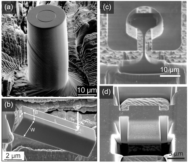
FIB machining of sharp notches with a specified orientation to the loading axis has enabled a number of fracture mechanics studies [629], and for in-situ TEM tensile testing, various milling protocols have been developed to produce electron transparent specimens [493].
To reduce ion beam induced surface damage defects, a multistep milling strategy is typically employed. In this approach, the beam voltage and current are sequentially stepped down to the last polishing step [4]. Among the still open questions are how much damage (amorphization, implantation) is induced by FIB milling into the structures and how the damaged zones affect the mechanical behaviour of the milled structure [484]. Key factors are the penetration (implantation) depth of ions and the collision cascade (amorphization) they trigger (see Sections III.1.3, III.2.3, and III.4.1).
Once other ion sources, in particular He, Ne, and Xe ion sources, became available, the hope was to be able to circumvent some of the Ga damage issues. Best et al. [496] found, however, that using either He, Xe or Ga for the machining of notches affected the measured fracture toughness value in all cases. While He ions were shown to yield suitable sharp notches with radii below \qty10nm, Xe ion beams were resolution limited. It was unclear how the penetration depth of the different ions affects the fracture toughness. Currently, combinations of FIB milling with other technologies are becoming more and more popular. For example, the option of laser machining of large volumes followed by FIB fine sculpting has recently become available from several manufacturers in a single setup.
IV.1.3 FIB in the semiconductor industry
In the field of semiconductor processing, FIBs are most relevant during the debugging of new products and for identifying production errors in the context of circuit edit and fault isolation, as well as for the repair of photomasks. Among other applications, FIBs have been used for failure analysis, fault isolation, TEM sample preparation, mask repair and backside circuit edit [630, 628, 631]. The ongoing scaling of the transistor fin, gate, and interconnect via linear and volumetric shrinking, as well as the introduction of new transistor technologies, has led to a reduction of the critical length scale from \qty22nm in 2012 to the current \qty3nm technology node to be introduced by all major manufacturers between 2022 and 2024 [632, 633, 634].
FIBs have been used since the 1980s for mask repair, initially using Ga and Au ions from LMIS and LMAIS [508]. However, staining from implanted ions was quickly identified as a problem limiting the application [509]. Later, the application of GFIS based H+, H, N, and He+ for phase-shift mask and extreme ultraviolet (EUV) mask repair was investigated [57, 506, 505]. For H, the minimal repairable dimension is reported to be \qty11nm, which is half of what could be achieved using electron beams [504]. The application of FIBID was investigated early on for adding missing material to masks and for repairing pin holes using Ga-FIB induced carbon deposition [510]. This has been extended using other deposition precursors. The addition of reactive gases such as Cl2 [635, 511], Br2 [511], XeF2 [636, 637], and O2 [637] has also been investigated for mask repair. These gases can significantly increase etch rates, remove carbon contamination and trigger resist development. In particular, XeF2 is now readily available in commercial FIB systems.
For circuit edit and fault isolation applications, Ga-FIB was used initially [514], but later Ne ions from GFIS instruments were employed. The latter yielded minimal trench widths of \qty14nm for high aspect ratio vias [507], and comparable/less collateral damage compared to Ga-FIB as measured from changes to ring oscillator timing [513]. Recently, GFIS-based H ions have been demonstrated for successful delayering [638]. Other source technologies, e.g. Cr ions from MOTIS [639], also show potential for circuit edit applications [640]. In general it is found that lower beam energies are be required while still maintaining a suitably high spatial resolution.
To better understand the effects of the beam profile on the achievable mill resolution, approaches have been developed to elucidate the probe current distribution [641, 642]. This is of particular importance for via fabrication and also for the fabrication of high aspect ratio holes/pores created by milling with a stationary beam. For these applications a good signal to noise ratio is needed for reliable endpoint detection, and a new figure of merit—SE yield per sputtered atom—can be defined. GFIS-based He and Ne milling of these structures promises superior spatial and temporal precision compared to Ga-based FIB processing [643]. However, GFIS-based milling suffers from the formation of gas bubbles and the creation of defects far below the milled surface of bulk samples [644].
IV.1.4 FIB for quantum materials
“Quantum materials” are materials in which quantum phenomena manifest in non-trivial ways, leading to response functions that are qualitatively distinct from those of standard electronic materials such as Si or Cu. These functions generally arise from the non-locality of quantum systems, with topology, frustration, and correlation all playing a central role [645, 646]. The key goal is to refine our microscopic or phenomenological understanding of these exotic quantum states, and develop predictors to find promising materials candidates within the vast space of possible compounds. A second main driver of quantum materials research are novel electronic applications that harness this exotic behavior for solving technological challenges. Most famous is quantum information technology, including quantum computation, which directly utilizes the entanglement and vast configurational space of quantum coherent systems. The search for the most effective materials platform to realize systems like qubits remains an open and very active field, i.e. the search for the "silicon" of quantum technology. Beyond coherent information processing, a large materials space has developed in sensing and data communication that utilizes quantum coherence indirectly, such as in strongly correlated oxides. The ubiquity of quantum mechanics is the greatest challenge, in that interdisciplinary efforts in materials science, chemistry, physics, engineering and informatics are required to realize these concepts in a useful way. In this search for new physics and new quantum platforms, the FIB excels as a versatile patterning tool that is ideal for rapid processing of non-standard materials [647], as it (a) avoids exposure to wet chemistry as compared to resist-based lithography, (b) can operate with crystallites and microparticles, i.e. non-standard samples that do not resemble polished wafers, and (c) enables 3D structure control that is critical to many electronic 3D quantum materials. The operational goal of this research is to fabricate hybrid structures that join micro-/nanostructures of a quantum material to a Si chip of conventional architecture, both to demonstrate advanced functionalities and to probe the underlying novel physics.
Quantum systems generically respond strongly to changes in their boundary conditions, in this case, their physical shape. FIBs enable the sculpting of non-trivial boundary conditions in crystals, which has been used to study and functionalize superconductivity, e.g. investigating the unconventional superconductivity of Sr2RuO4 [515, 516], and studying Josephson vortices in strongly layered high-Tc superconductors and their excitations [517, 518]. Controlled patterns guide the motion of Abrikosov lattices by surface structuring [520] towards non-trivial electronic responses such as vortex diodes [521, 522]. Further towards superconducting applications on small dimensions, FIB milling also enables direct nanopatterning of Josephson junctions, nanowires and nanoSQUIDs [648, 649]. The nanoSQUIDs are used for magnetization reversal detection of individual magnetic nanoparticles [529, 540] and for magnetic and thermal sensing in scanning SQUID microscopy [532]. In microwave circuits, nanoSQUIDS can be used as tunable inductors, e.g. to enable tuning of the resonance frequency of microwave resonators [526].
Beyond superconductors, other exotic materials and properties can be probed, such as quasiparticle transport in ultra-clean metals [547], and the magnetic exchange bias in time-reversal symmetry breaking topological semi-metals [650]. Reducing the sample size to the micron scale further enhances the contribution of surface properties to the overall physics. This is particularly important in the quest to probe the contribution of topologically protected surface states, which have been proposed to enable novel electronic and spintronic applications in topological semi-metals [548, 551, 549, 550]. Precise FIB machining also enables optimization of the edge quality of structures, which is a prerequisite for the fabrication of efficient superconducting single-photon detectors (SSPDs) [572]. In addition, the flexibility of FIB processing on highly 3D substrates has enabled FIB milling on top of an optical fiber [573].
Subtractive FIB processing has also been applied in the fields of spintronics and magnonics. Examples include guiding and control of propagating spin waves, which has been enabled using the Ga-FIB [546]. High resolution metal free FIB processing using GFIS ion species has also enabled fine tuning of the interaction of spin waves across gaps [543].
Not all applications of FIB aim to alter the material. In addition, there is a wide class of FIB milling experiments aimed at probing the bulk properties of novel materials that can be difficult to access when the material is in its native form, e.g. microcrystals that are too small for conventional measurements. This has allowed insights into microscopic effects on critical charge transport in Fe-based superconductors [523, 524], the determination of topological bandstructures in microcrystals [525], and probing of the switchability of anti-ferromagnetic states under the high current densities achievable in FIB-machined crystals [651, 652]. The rich physical responses of quantum materials tend to be rooted in the competition between multiple electronic ground states, which leads to a strong (and potentially discontinuous) change in their properties under weak applied stimuli [653]. One can hardly overstate the importance of residual stress in the samples, with a famous example being the enigma of the “3K phase” of superconductivity in Sr2RuO4, which originated from strain mismatch [553]. Here a crucial advantage of FIB milling over mechanical sample preparation techniques, such as polishing or wire sawing, is its kinetic nature, which results in samples of low residual stress. Precision control over the physical shape of a sample has also enabled microscopic control over desired strain fields and their gradients, which imprint correlation landscapes into quantum materials [554, 555].
IV.1.5 FIB for photonics and plasmonics
Miniaturized on-chip photonic components are designed to guide or focus light while having a footprint as small as possible. The fabrication of these relies mostly on conventional large-scale lithographic techniques, but there are applications where a maskless direct-write strategy has significant advantages. Prime examples are localized light sources, with the extreme case of single photon sources, where the optical component often has to be built around a pre-localized (quantum) emitter. Such quantum emitters may be defects in wide-bandgap materials (see Section IV.2.4), where out-coupling of the generated quantum light is typically hindered by the large refractive index of the host material, e.g. diamond. Here, \Acfib milling either using Ga ions [559, 560, 224] or, to reduce Ga-induced damage, O ions [556], has been successfully used to engrave solid immersion lenses that enhance photon collection efficiencies. In the same manner, photonic crystal cavities with small mode volumes have been milled into a suspended diamond layer around pre-localized quantum emitters and proven to enhance spontaneous emission [561]. An even further reduction of optical mode volume can be achieved using metallic nanostructures, since these have the ability to concentrate light below the diffraction limit by collective excitations of the free electron gas [654]. Since such plasmon-polariton modes are strongly dependent on geometry, FIB processing is a powerful tool for rapid prototyping of nanoscale resonators, sub-wavelength apertures [655] and optical antennae [656].
Furthermore, extreme plasmonic field confinement allows the detection of molecular species down to the single molecule level by surface enhanced Raman scattering [657] (the prime example), enhanced fluorescence [658], or enhanced Förster resonant energy transfer [659]. The latter two examples employ Ga-FIB milling to fabricate an antenna-in-a-box geometry, where the gap region of a dimer antenna provides the local electric field enhancement and correspondingly an enhanced local density of optical states. The remaining metallic film around the antenna blocks fluorescence from contributing to the background. In general, Ga-FIB top down patterning, especially of single-crystalline Au or Ag nanoflakes, is often employed for high-fidelity rapid prototyping of plasmonic components [660, 599, 661, 662, 663]. When comparing the performance and material properties of plasmonic antennae, electron beam lithography (EBL) may lead to better results than FIB milling, depending on the actual geometry and processing conditions, especially in case of Ga-FIB [664]. However, \Acebl fails in fabricating truly 3D profiles. In contrast, FIB milling has been used to e.g. mill out 3D Janus plasmonic helical nanoapertures for polarization-encrypted data storage [665].
A particularly beautiful example of 3D FIB-milling capabilities combines local material removal by Ga-FIB milling of a suspended gold film with low dose Ga ion irradiation at selected edges. The latter induces a stress distribution that leads to up- or downward bending of the predefined structures [666]. This nano-kirigami approach has been demonstrated for various designs realizing optical chirality, polarization and phase engineering, and showing potential for opto-mechanical applications [568].
The resolution and shape fidelity of \Acfib milling with light ions stands out compared to any other lithographic techniques [471, 226], but comes at the cost of the slow speed of the inherently serial process. To resolve this issue, lithographic large area processing by \Acebl can be combined with e.g. He-FIB for the ultimate in resolution. Extremely narrow gaps between large areas of lithographically defined plasmonic Au [577] and Al [574] antennae have been realized using this approach. By combining Ga-FIB patterning with He-FIB patterning, the achievable spatial resolution can be significantly improved while keeping a reasonable processing speed [575]. Another approach to increase the speed of top-down FIB processing relies on milling only the outlines of desired plasmonic features, which are then subsequently obtained by peeling off the surrounding material [667, 668, 579]. This “sketch and peel technique”, combining Ga-FIB patterning for the outlines with He-FIB for the definition of ultra-narrow gaps, was used to reproducibly demonstrate strong coupling in plasmonic dimer antennae [580].
IV.1.6 FIB fabrication of custom probes
Since FIB milling is not restricted to planar sample geometries, a vast body of research exists on the modification of optical fibers [570], nanofibers [571] and nano-probes. The comprehensive review by Sloyan et al. [570] presents examples for optical near-field imaging, plasmonics, beam shaping, fiber-based photonic cavities, fiber-chip coupling, and many more. He-FIB manufacturing was reviewed in detail by Allen [471]. Direct control over precise nanostructure geometries by FIB milling is especially interesting for near-field optical microscopy (NSOM), where a metal coated glass fiber tip localizes the excitation and/or collection of light by making use of a nanoaperture or antenna for plasmonic field concentration. In applications concerned with NSOM, FIB milling has been employed to fabricate high-definition plasmonic circular nanoapertures at the apex of a metal coated glass fiber tip [602]. Further signal enhancement and fluorescent background reduction can be achieved by adding a tip at the aperture rim, combining the concepts of scattering and aperture NSOM [669, 670]. While the tip was grown by FEBID in these works and metallized afterwards, later work engraved the tip-on-aperture geometry into the metallic (Al) fiber coating by Ga-FIB milling and tuned the tip resonance to behave as a monopole antenna, thus achieving single molecule imaging [604] and imaging of proteins on cell membranes [605]. Additional geometries realized in this way are bowtie nanoapertures on the end of metal-coated fiber tips [603] and square plasmonic nanoapertures in pyramidal cavity structures [585], with the latter example employing He-FIB milling.
Further specific geometries of metallic tips and metal-coated fiber tips have been fabricated to control the plasmonic response for other purposes. These include nanocones for resonance and radiation pattern tuning by Ga-FIB milling [607], nanopyramids for optimizing local electric near-fields by He-FIB milling [601], and nanoslit gratings into the conical taper of metallic tips for nanofocusing upon far-field illumination, again by Ga-FIB milling [608]. FIB milling has also been been employed to modify AFM probes for specialized applications. In one example, FIB-milling was used to partially remove the magnetic layer from a commercial magnetic force microscopy (MFM)-probe. The V-shaped nanostructure remaining on one side of the triangular pyramid results in enhanced magnetic phase contrast without compromising spatial resolution [615]. Another example employs nanoscale apertures milled into hollow pyramidal AFM tips, that can be loaded with liquid to dispense attoliter volumes and create droplet arrays [610]. Such tips can also be be used for the manipulation and analysis of single cells via so-called fluidic AFM [611]. Tips can be sharpened using FIB milling and can also be detached from their initial substrate and mounted onto a cantilever of choice with the help of a micro-manipulator. This technique has, for example, been used to produce customized tips with high aspect ratios [613]. In other work, the AFM cantilevers themselves have been fashioned with FIB-milled apertures to enable ion implantation through those apertures aided by scanning probe alignment [612]. \Acfib milling of larger patterns into piezoresitive cantilevers has been used to increase deflection sensitivity to optimize cantilever performance [614]. Recently, Ga-FIB milling has also been used for shaping AFM tips to produce mesa structures on the cantilever onto which Nb nanoSQUIDs have been fabricated. Such structures simultaneously enable topographic, magnetic and thermal imaging [532].
IV.1.7 Outlook
As an all-in-one processing tool, the FIB provides a versatile platform for flexible and fast top-down fabrication and prototyping of nanostructures and devices.
To further advance these developments, FIB technology needs improvement not only in spatial resolution but also in the in-situ control of the material removal process. Critical issues include material sputtering selectivity and increasing the signal to noise ratio of SE monitoring during the milling of high aspect ratio structures. However, FIB top-down nanofabrication is intrinsically limited by the fact that the energetic particles and the chemical species involved cause structural and chemical damage or changes, such as amorphization or poisoning. While traditional Ga-FIB still represents the FIB standard, some of the aforementioned fundamental limitations may be resolved by using other ion species, such as those offered by GFIS, MOTIS, LoTIS, PFIB or LMAIS (see e.g. Section II.1).
Additionally, scale-up of FIB based top-down nanofabrication will only be achieved when increased throughput and reproducibility are realized. Here, advances in software and hardware tools for e.g. modeling-informed automated operation will be beneficial, also allowing in-line integration of FIB processing into larger (nano)-fabrication pipelines. Theoretical knowledge, modeling and simulation tools that provide precise descriptions of FIB modifications to materials, from the atomic to the microscopic scale, are a prerequisite for predictive design and for the realization of tailored properties and functionalities of nanostructured surfaces and operating devices.
There are also opportunities for coordinated FIB system development based on specific experimental needs. For example, strong interest in emerging fields such as quantum technology, as well as novel miniaturized platforms in the fields of microfluidics for lab-on-a-chip or organ-on-a-chip developments, would benefit from synergies with theory groups and tool makers in the FIB application community.
IV.2 Engineering materials properties through defects
In addition to the subtractive nanofabrication applications described above, site-specific and dose-controlled irradiation of samples with the FIB is used to tune material properties in spatially defined regions down to the nanoscale and even down to the single-atom level, without surface erosion or deposition. These applications are based on the local introduction of varying concentrations of defects (vacancies, dopants, and dopant-vacancy complexes), controlled by the dose.
IV.2.1 Basics of irradiation induced defect creation
A common technique used to create defects in crystals relies on bombardment with high energy ions or electrons [671, 246, 672], and in some cases photons, protons or neutrons [673]. For example, tuning the fluorescence properties or the refractive index of a material for optical applications by bombardment with ions is a well-established technique [674, 675]. Ion implanters are often employed for such applications. Since these deliver broad beams with spot sizes in the millimeter regime, a lithographically defined mask is needed when higher spatial resolution is required. However, the large collision cascades that are inherent to both high energy ion beams and light ion bombardment make mask design rather challenging. This is where FIB processing comes into play.
As described in Section III, the incident ion induces a collision cascade in the solid with a size that is determined by the target material and the ion’s kinetic energy, as defined by the primary beam voltage. In a simplified picture, when a recoil is generated, it leaves behind a vacancy and forms an interstitial when it comes to rest[676]. In reality, defect clusters and amorphous pockets may form depending on the target material[677] and on the ion mass and energy [678]. Larger defect structures such as these are usually undesirable for defect engineering, as their properties are less well defined than those of simple defects. They are best avoided by using light ions, which cause more dilute collision cascades than heavier ions due to the lower nuclear stopping power. The recoils in these cases are also less energetic because of the unequal masses of the ion and target atoms. In addition, light ions cause less sputtering, which is generally an unwanted effect in defect engineering. Regardless, the applied ion doses and beam parameters still have to be carefully adjusted. Considering the example of He ion irradiation of Si and Cu substrates, Livengood et al. [644] differentiate the various defect regimes according to dose, ranging from individual point defects at low fluence, to extended subsurface microbubbles at very high fluence. While the picture will vary somewhat for other ion-substrate combinations, the same overall trends apply.
Table LABEL:table:property_engineering gives the reader a flavor of the breadth of FIB based defect engineering applications, categorized according to the specific materials property engineered (electrical/electronic, magnetic, optical, quantum, chemical, thermal, and mechanical). Further examples can be found in the review articles by Gierak [679], Orús, Córdoba, and De Teresa [680], and Allen [471].
| Engineered Property | Experiment | Ion | Material/Device |
|---|---|---|---|
| Electrical & electronic | conductivity tuning | He | graphene [681, 682, 683, 684, 685, 686], few-layer/monolayer MoS2 [687, 688, 689], epitaxial MoS2 [690], few-layer/monolayer WSe2 [691, 688], monolayer WSe2 [688], InGaZnO thin film [692] |
| Ne | Si nanocrystals (self-assembly of) in buried silica layer [410] | ||
| Ga | AlGaAs/GaAs quantum wires [693, 694, 695, 696], GaAs quantum constrictions [697] GaN nanowires [698], 2D MoSe2/graphene heterostructure [699], MoSi superconducting thin film [700], In2O3 thin film [701], Al2O3 film [702], ZnO and VO2 [703] | ||
| Si | AlGaAs/GaAs quantum wires [704] | ||
| formation of barriers and nanoconstrictions | He | superconducting electronic circuitry including Josephson junctions and nanoSQUIDs in YBCO [705, 706, 707, 708, 709, 710, 528, 711] and MgB2 [712], nanoconstrictions in BSCCO [713, 714] | |
| Ga | quantum dots in single-walled CNT [715] | ||
| tuning thermoelectric properties | He | MoSe2 thin films [716] | |
| tuning superconductivity | He | periodic arrays of artificial pinning sites in YBCO [717, 718] | |
| pinning ferroelectric domains | He | PbZr0.2Ti0.8O3 thin film [719], multilayer MoTe2 flake [720] | |
| ferroelectric phase change | He | induced ferroelectricity in HfO2 [721], conversion to paraelectric phase [722] | |
| Ga | HfO2 thin film [723], damage in ferroelectric capacitors [724, 725] | ||
| Magnetic | tuning magnetic anisotropy | He | Co/Pt multilayers [726], Ir17Mn83/Co70Fe30 bilayer [727], Co-based thin-film stack [728, 729], Co/Pt/Ru multilayer system [730] |
| skyrmions in Pt/Co/MgO thin film [731], and in Pt/Co60Fe25B15/MgO thin film [732] | |||
| Si/Ge | Bi and Ga substituted YIG [733] | ||
| Ga | CoPt multilayers [734], Fe78Ni22 thin film [735], Ir/Co/Pt multilayers [736] | ||
| skyrmions in FeGe thin plate [737], and in Co/Pt multilayers [738, 739, 740] | |||
| tuning metamagnetic transition temperature | He | FeRh thin film [741] | |
| inducing ferromagnetism | Ne | Fe60Al40 thin film [742, 544] | |
| Ga | Fe60Al40 alloy [743] and Fe78Ni22 on copper [744] | ||
| magnonics | Ga | patterned Fe78Ni22 films [735], spin wave optical elements in YIG [745] | |
| Optical & quantum | tuning photoluminescence | He | SiNx membrane [746], monolayer MoSe2 [747], InGaAs/GaAs quantum well [748], reducing parasitic fluorescence in hBN [749] |
| Ga | AlGaAs/GaAs and GaInAsP/InP quantum wells [750] | ||
| tuning of passive optical components | He | plasmonic resonance in graphene nanostructures [751], Bragg grating in silica nanofiber [752] | |
| Li | Si microdisc nanophotonic resonator [753] | ||
| Ga | ZnSe quantum dot micropillar cavitities [754], periodic poling of LiNb waveguide [755] | ||
| creation of photoluminescence, quantum emitters and qubits | He | NV centers in diamond with substitutional nitrogen [756, 757], Si vacancy centers in SiC [758, 759], luminescent defects in monolayer MoS2 [760, 761] | |
| Li | Si vacancy centers in SiC [762] | ||
| Si | Si vacancy centers in diamond [763] and diamond nanostructures [764], W and G centers in silicon [765], isotopic enrichment of 28Si to increase spin qubit coherence times [766] | ||
| Ar | NV centers in diamond [767] | ||
| P | deterministic single-atom implantation of 31P into Si [293] | ||
| Ga | luminescent defects in hBN [768, 769], monolayer WSe2 [770], MoS2 and WS2 [771] | ||
| Ge | Ge vacancy centers in diamond [772] | ||
| Sb, Si | deterministic single-atom implantation into Si [773] | ||
| Xe | recoil implantation of color centers in diamond [774], spin defects in hBN [775], water assisted fabrication of extended defects in hBN [776] | ||
| Bi | qubits in silicon and germanium [777] | ||
| Chemical | enhancing chemical etch rates | He | Si3N4 thin film [778], SiO2 thin film [779], mono-/bilayer MoS2 [780] |
| enhancing catalytic activity | He | MoS2 and MoSe2 flakes [781] | |
| nucleation of growth | He | epitaxial graphene on SiC [782] | |
| Co | CoSi2 nanowires in Co-saturated Si [783] | ||
| Ga | InAs dots on GaAs [784], Ge dots on Si [785, 786] | ||
| functionalization | Ga | graphene (fluorination using XeF2) [787] | |
| tuning surface wettability | Ga | molecular self-assembled monolayer [788] | |
| Thermal | reducing thermal conductivity | He | Si nanowires [789], Si membrane [790], VO2 nanowires [791], Bi2Te3 nanoribbons [792] |
| Mechanical | tuning Young’s modulus | He | monolayer MoSe2 [747] |
| Ga | polymer [793], hydrogels [794] | ||
| gas bubble effects | He | nanobubble superlattice in Cu [795], nanobubbles in Si [796], diamond [797], Eurofer steel [798], W [799], ultrafine-grained W and W-Cu nanocomposite [800] | |
In the remainder of this section we focus on those applications in Table LABEL:table:property_engineering that are concerned with engineering the electronic, magnetic, and optical/quantum properties of materials, with additional detail on property engineering of low-dimensional materials (in particular, thin films and 2D materials). The study of irradiation damage mechanisms (e.g. the formation of gas nanobubbles) is also discussed.
IV.2.2 Engineering electronic properties
From the outset, FIBs have been used to fabricate electronic devices at the nanoscale. Early examples, using Ga-FIB milling, are the fabrication of GaAs quantum wires [693] and a quantum wire transistor [695]. More recently, however, Ga-FIB irradiation at lower dose was employed for the fabrication of a lateral diode based on a 2D heterostructure of MoSe2 and graphene [699]. Here, the preferential sputtering of Se locally transformed the top MoSe2 layer into a quasimetallic state, generating a pn junction with rectification performance comparable to that of a vertical diode. These examples illustrate a development from the prevalence of subtractive materials modification by FIB milling, to increased interest in engineering the electrical and electronic properties of materials at lower dose through defects.
Here, light (and often preferably inert) ion beams are of relevance due to their high resolution defect engineering capabilities. Ion beams of electronically active elements (e.g. P, Sb, As) also have the potential for interesting applications, such as local doping with high spatial resolution or the generation of qubits by SII. For applications in superconductivity, Josephson junctions, i.e. weak links between two superconducting electrodes, are key elements for superconducting electronic devices. For Josephson junctions based on conventional metallic superconductors, such as Nb or Al, thin-film devices with grown insulating (I) or normal conducting (N) barriers, sandwiched between superconducting (S) electrodes, are well established. However, in the case of the high-TC cuprate superconductors this as-grown approach does not produce well-defined SIS or SNS junctions, due to the complex nature of these materials and their strong sensitivity to defects on the atomic scale. As an alternative approach, the local FIB-enabled modification of superconducting thin films in order to “write" thin N or I layers as Josephson barriers in prepatterned thin film structures has been successfully demonstrated. Here, the high spatial resolution offered by He-FIB has been shown to be of great importance. Prime examples are the fabrication of insulating or normal-conducting barriers in yttrium barium copper oxide (YBCO) or MgB2 thin films by He-FIB irradiation that locally suppress superconductivity on the nanometer scale [705, 712, 707], and the creation of He-FIB-induced nanoconstrictions in Bi2Sr2CaCu2O8 (BSCCO) single crystal flakes. The latter form the basis of two-dimensional cuprate nanodetectors with single telecom photon sensitivity [713, 714]. Moreover, He-FIB irradiation of YBCO films has produced artificial pinning arrays with unprecedented lattice constants down to \qty30nm [717, 718], which opens a new regime for motion control of Abrikosov vortices in superconducting fluxonic devices.
Due to the nanoscale beam size that is achievable with FIBs, in particular with GFIS-based FIBs, these are ideal tools for the fabrication of single quantum dots, tunneling devices and single electron transistors. Examples include the fabrication of single electron transistors in Si/SiO2 stacks [410] and the fabrication of single quantum dots in carbon nanotubes [715].
IV.2.3 Engineering magnetic properties
Ion irradiation in general has been used for many decades for the modification of magnetic materials [801]. To achieve this sort of modification, complex and expensive masking processes have to be used unless one employs FIBs, which can modify the magnetic properties locally with nanometer precision. In 1989, Ishii, Nonaka, and Hatakeyama [733] used Si and Ge ions from a LMAIS-FIB to create nucleation sites for controlled switching of the magnetization in Bi- and Ga-substituted yttrium iron garnet (YIG) films. Ga-FIB processing has also been used for creating read/write heads [802] for magnetic hard disks, and for modern approaches such as magnetic random access memories composed of magnetic multilayer structures [803]. FIB-induced local changes in magnetic anisotropy have been used to create isolated tracks of single domain islands in recording media [804] and to control the injection location and field dependency of magnetic domain walls in multilayers with perpendicular magnetic anisotropy (using Ga- and He-FIB) [726]. In the case of Co nanowires fabricated by FEBID, irradiation with Ga-FIB has allowed modification of the propagation speed of the magnetic domain wall [805]. In some materials, FIBs can be used to generate ferromagnetism in selected regions, such as in paramagnetic FeAl alloys. For example, the spatially resolved creation of disorder-induced ferromagnetism using Ga-FIB modification has been demonstrated by Menéndez et al. [743], achieving a spatial resolution of below \qty100nm with the possibility of erasing the pattern by annealing. Later, Fe60Al40 was studied in depth for order-disorder phase transitions and ferromagnetic resonance (FMR) in magnetically written single structures induced by Ne-FIB irradiation [742, 544]. Paramagnetic regions in non-magnetic materials can also be created by FIB irradiation, as has been done for InGaAs using Ga-FIB to create a spin filter device [806].
The continued quest for an increase in storage density in combination with novel data processing approaches (i.e. neuromorphic computing) has triggered the development of advanced patterning of complex magnetic alloys and multilayer systems [807, 808, 809]. In these systems various interactions due to the intrinsic anisotropy, or lattice and system geometry, may lead to topologically protected spin configurations such as skyrmions or the controlled formation and transport of spin waves. Here the FIB stands out, as it enables tuning of magnetic anisotropy landscapes without any topographical changes to the devices. This was demonstrated for the nucleation control of skyrmions in Co/Pt multilayers using Ga-FIB [739] and He-FIB [738], and through the patterning of skyrmion racetracks in a Pt/Co/MgO thin film using the He-FIB [731]. The patterning of dots as nucleation sites within a low-dose racetrack using He-FIB realized both the deterministic generation and movement of skyrmions with nanometric precision [732]. Finally, spin-wave optical components such as graded-index lenses for applications in magnonics can be created by ion induced modification of the local magnetization in YIG, which corresponds to an effective refractive index for spin wave propagation. Here, \qty50keV Ga-FIB was employed and the penetration depth of about \qty100nm allowed for an effective refractive index of up to 1.8, comparable to light-based optics. Since this depth was only one third of the actual device thickness, the much lighter He ions are expected to significantly improve the optical device performance [745].
IV.2.4 Engineering optical/quantum properties
Typical applications of ion irradiation in optics include the local change of refractive index and the creation of fluorescence [810]. However, since FIB processing is serial and the penetration depth is limited, the use of the FIB in this area is mostly of interest in cases where a small number of ions needs to be placed with high spatial accuracy. A particularly beautiful example is the tuning and imaging of resonant optical modes in a silicon disc resonator using Li-FIB [753]. A low beam current of \qty1pA at \qty3.9kV acceleration voltage was used to radially raster scan in pulses of ions while the transmitted light passing through a critically coupled waveguide was monitored. The optical shifts observed could be attributed to ion damage and a rapid thermal (and thus reversible) response. Knowledge of this time-varying response was used to enable imaging of different optical modes with minimum device degradation.
The spatial accuracy of defect creation using the mask-less FIB approach becomes especially beneficial in the field of quantum technology. Here, a defect in an otherwise ideally perfect crystal can take the role of an artificial atom emitting quantum light. Furthermore, the defect may exhibit electronic and nuclear spin degrees of freedom that may be coherently coupled to the emitted quantum light, turning the defect into a solid state quantum bit (qubit). The most popular example of a defect-based quantum emitter, or qubit, is the nitrogen vacancy (NV) center in diamond. Diamond NV centers are routinely fabricated using ion implanters [811], but have also been realized using He-FIB processing [756, 757]. FIB implantation of Si ions has been used to realize nearly lifetime-limited single Si vacancy (SiV) quantum emitters in diamond nanostructures [764]. This maskless approach achieved \qty≈32nm lateral precision and \qty<50nm positioning accuracy, and is thus promising for the development of scalable solid-state quantum information processors. Focused Si ions at \qty35keV with beam diameters of have also been used to fabricate negatively charged silicon vacancies (V) in 4H-SiC, with single emitters observed starting from 40 ions per irradiated spot [812]. A comparative study by the same author using H, He and C ions showed that He ions produced the highest defect concentration, while the lowest brightness emitters were observed for C ions [813]. In addition, Li-FIB has been employed for the creation of Si vacancies in SiC [762]. Recently, focused Ar8+ ions from an EBIT were also used for NV-creation in diamond [767]. A particularly interesting study made use of Xe-FIB for recoil implantation of targeted group IV dopants in a deposited surface layer [774]. In this work, Pb, Sn, Ge and Si color centers in diamond were fabricated with a spatial accuracy of better than \qty50nm in combination with an ultra-shallow doping profile. So-called G and W centers in Si have recently been demonstrated using Si-FIB to create spatially resolved single defect centers of this type for application as quantum emitters in the telecom band [765]. And in a very recent approach, a dedicated FIB system equipped with a ultra-high vacuum (UHV) sample chamber [814] was used to suppress unwanted isotopes in Si that would otherwise limit coherence times and therewith the performance of solid-state spin qubits. This was achieved using a LMAIS source to implant 28Si++ into natural Si, lowering the level of unwanted 29Si to the single-digit ppm range without introducing contamination from the FIB processing [766]. The deterministic placement of single atoms (e.g. Sb or P) into Si to act as qubits is another challenge where progress has recently been made [773, 293]. While the two cited works are a clear demonstration of the placement accuracy of single (or few) atoms using a FIB, the approaches rely on implantation into a host material that can also double as an active detector of the ion impacts.
In parallel, 2D materials have been heavily explored as hosts for usable quantum emitters e.g. sources of single photons [815]. Here, ion irradiation can be used to both tailor the optical properties of the 2D system [816] as well as to produce defects that introduce novel optical activity [817, 818]. He-FIB processing in particular has been used for the site-selective creation of defects in e.g. 2D MoS2 [761]. While the exact type of defects being introduced is still under investigation (true for most luminescent defects in 2D materials), they are expected to cause highly localized trapping potentials for exciton emission. Encapsulation with hBN leads to very narrow linewidths of the emission lines in the visible range, below the neutral exciton [761]. He irradiation has also been shown to result in a five-fold reduction in background and parasitic fluorescence, enabling the isolation of bright and stable quantum emitters in hBN [749]. Recent results using Ga-FIB patterning indicate that the formation of luminescent defects is positively correlated to material swelling rather than material removal by milling [769]. This helps to explain earlier results on the generation of defects by Ga-FIB, where it was not clear whether the single photon emission was actually generated inside the milled holes, at their edges, or in the damaged region near the edges [768].
IV.2.5 Engineering of low-dimensional materials
2D materials such as graphene and atomically thin transition-metal dichalcogenides are expected to play an important role in the realization of future electronic and optoelectronic devices and there exists a significant body of work in which FIB based defect engineering has been used to tune the unique properties of these materials. In fact, as can be seen in Table LABEL:table:property_engineering, the majority of materials that are used in FIB based defect engineering work are indeed low-dimensional (thin films, 2D materials, and nanowires). The simple reason for this is that typical FIB instruments deliver beams with energies of several tens of keV, which limits the ion penetration depth. For example, in most materials the maximum penetration depth of the ubiquitous \qty30keV Ga ion beam is around \qty60nm, which severely limits possibilities for property engineering of bulk materials. While lighter ions of the same energy penetrate more deeply, for many defect engineering applications implantation of the ion into the material is not actually desired. Rather, it is the local damage created by the ion in transit that is leveraged. Therefore, low-dimensional materials are often the ideal testbed material for defect engineering using the FIB. Notably, an increase in ion energy typically causes a decreasein defect production in 2D materials [819], such that lower beam energies are in fact better suited for efficient materials modification in these cases.
An example of FIB based defect engineering of a low-dimensional material is the use of the He-FIB to tune the electrical resistivity of 2D MoS2 [687]. In the cited work, the electrical resistivity of the MoS2 monolayer was tuned from semiconducting to insulating depending on the vacancy defect concentration, as controlled by the irradiation dose. Above a certain threshold dose, total amorphization (i.e. disordering) of the material occurs. By irradiating samples locally in specific patterns with fluences below the total amorphization threshold, the FIB can be used to tune the defect density and hence the electrical conductivity in spatially defined regions at the nanoscale. For example, using the He-FIB and a line irradiation strategy on 2D MoS2, a neuromorphic memtransistor device has been demonstrated [689]. Similarly, Ga-FIB has been used for defect creation in supported graphene, with MD simulations providing insight into the effect of irradiation angle on the lateral damage distribution [820]. He-FIB line irradiation of graphene has also been used to create graphene nanoribbons [686], which opens up a band gap in graphene due to quantum confinement. Tuning of the ribbon width and hence the size of the band gap is a key step toward the use of graphene in electronic applications. As discussed in Section III.2.3, for supported graphene the minimum achievable nanoribbon width is limited by the influence of the backscattered ions from the substrate [370].
Other defect engineering applications concerning 2D materials include the use of Ga-FIB in combination with the simultaneous flow of XeF2 gas for the localized fluorination of graphene [787], and the use of the He-FIB to create localized defects in graphene to serve as nucleation points for the epitaxial growth of hBN [782]. An example of defect engineering of a 1D structure is the employment of localized He-FIB irradiation to induce regions of disorder in a silicon nanowire in order to tune the thermal conductivity along its length [789].
IV.2.6 Study of irradiation damage mechanisms
Fundamental curiosity and the need for experimentally straightforward replacements for long-duration reactor-based irradiation experiments have resulted in FIB instruments being used for the systematic study of irradiation effects on structural materials. In order to simulate irradiation damage caused by particles, for example, He+ ions are a convenient species to use. A further advantage of using an inert species such as He is that fundamental studies of irradiation effects can be made while avoiding alloying effects and grain boundary embrittlement, as can occur with a metallic ion species such as gallium [621].
A phenomenon that was discovered several decades ago is the formation of He nanobubbles upon He ion irradiation of various metal targets. These nanobubbles form as a result of vacancy defects and He interstitials that diffuse and recombine to produce gas clusters. However, fundamental experimental studies of the resulting changes in the mechanical properties of the target material were for a long time confined to the use of large-scale ion accelerators and plasma devices. The introduction of the He-FIB changed this, enabling the first systematic dose-controlled irradiation studies. Using the He-FIB, gas bubble phenomena that had been observed in large-scale experiments have been reproduced with much greater control over the experimental conditions. Initial He-FIB studies in this area used Si targets, mostly driven by the need of the semiconductor industry to evaluate the invasiveness of He-FIB processing [644]. Later studies included the investigation of He gas-bubble superlattices, using single-crystal Cu as a simple model system and probing the effect of the superlattice on the mechanical properties of the host material using in-situ TEM nanoindentation [795]. Since samples are irradiated with the He-FIB on the nanoscale, individual grains and grain boundaries can be targeted in polycrystalline samples [821]. By increasing the dose, the coalescence of nanobubbles forming crack planes that ultimately result in blistering and delamination can also be studied with a level of control that was previously unattainable [799]. Furthermore, irradiation induced mechanical property changes of a number of materials that are directly relevant for nuclear applications have been investigated using the He-FIB combined with nanoindentation, e.g. in studies of Eurofer steel [798], W [822], ultrafine-grained W and a W-Cu nanocomposite [800].
IV.2.7 Outlook
The use of the FIB for property engineering down to the nanoscale is now well established. Recently, strong efforts have been underway to increase the spatial resolution and control of the technique even further, with the ultimate goal of creating single defect centers or implanting single impurity atoms for applications in quantum technology. Here, a significant challenge is posed by the intrinsically stochastic nature of both the production of ions from most FIB sources and of the ion-solid interaction itself. The deterministic placement of single ions either into the bulk or at a surface thus pushes the FIB technique to its fundamental limits.
There are two distinct approaches that are being pursued for realizing deterministic SII using the FIB. One is to count the ions as they travel to the sample and the other is to detect individual ion impact events, ideally in an universal manner. The first approach can be realized by using an Paul ion trap as a deterministic source of single ions [827, 828]. While the presence of the ion can be unambiguously proven, ejecting the ion and re-loading the trap is time-consuming and the spatial localization of the eventual impact event using ion-optical elements causes significant losses. Given that the probabilities for the creation of specific defects are usually low and highly material dependent (see also Section III.2) this deterministic ion source approach is appealing, but technologically extremely demanding. Alternatively, ion columns can be equipped with image-charge detectors that count ions produced from different types of ion sources. The beam is directed toward the sample only if an ion is detected. In this way, imperfect detection efficiencies can be mitigated since all non-detected ions are automatically blanked [193]. The drawback of this technique is the large charge state (at least ) that is necessary for detection of the image charge, requiring ion sources such as an EBIT. Here, Ar18+ ions created by an EBIT have been successfully used [194]. Light ions are excluded from this technique, unless the sensitivity of the image-charge detectors can be significantly increased, and this method also presents significant technological challenges for column design.
The second approach, i.e. the detection of individual ion impacts on the sample, could in principle work for any ion source. Promising attempts combine an on-chip IBIC detector [199, 829] with a plasma ion source and a near-surface aperture in an AFM cantilever [293]. Here, scanning of the aperture realizes the spatial localization [830, 831, 832] and thus allows use of various types of ion source, including broad beam implanters. While this is an important step for all quantum devices that tolerate a nearby pn-junction and amplifier, other device concepts e.g. in photonic quantum technology, require truly agnostic sample detector concepts. Conventional SE detectors (Everhart-Thornley, see also Section II.3) or novel detector types (e.g. channeltrons [777]) may work as such, but suffer from their strong dependence on the SE yield, which is unknown for most materials and is very surface dependent. There is also a need for a better understanding and prediction of SE generation and expected detection yields, and for the development of advanced SE detection schemes with detection efficiencies approaching \qty100% [833, 777]. Instead of detecting all ion impact events (that may each come with a small probability of creating the target defect), one may instead detect device function in-situ while delivering ions to the target locations. A combination of short dwell times at extremely low current results in a Poissonian probability of either one or zero ions per shot and the process may be stopped once the desired device operation is achieved. Here, the technological challenge of these implementations involves the co-integration of an extremely sensitive fluorescence detection setup [834, 835].
In conclusion, several promising development routes for SII are currently being pursued that are showing first promising results. Whether modifying the ion supply toward being deterministic or enhancing the detection capabilities toward single-ion sensitivity (or a combination of both) will finally lead to success is still an open question.
IV.3 FIB-based imaging and tomography
Multiscale imaging of complex systems is becoming increasingly important. For example, to understand data transmission in the brain or chemical energy storage in a battery, one needs to capture the “big picture”, ideally in three dimensions, as well as resolve features down to individual atoms. This is where FIB based techniques play a central role, by direct imaging using light ions such as He, by 3D volume imaging combining FIB slicing with SEM, and by preparing thinned cross-sections and specialized geometries for TEM and APT.
IV.3.1 A brief history of FIB-based imaging and analysis
The enormous potential of electron microscopy for imaging the structure of condensed matter became clear with the invention of the TEM in 1932 [836] and soon thereafter first images of bacteria [837, 838] and virus particles [839] proved the same for the life sciences. The introduction of ion microscopy for imaging, however, took much longer. Pioneering work was carried out in the 1970s by Levi-Setti and co-workers, who experimented with a scanning transmission ion microscope using up to \qty65keV H ions from a GFIS and published images of myofibrils from rabbit muscle [36]. However, since the achievable lateral resolution of ion microscopy had always been inferior to that of electron microscopy, ion microscopy was not used for nanoscale imaging until the early 2000s with the invention of the HIM [21, 25] (see Section IV.3.2).
The breakthrough in the use of ion microscopy for sub-cellular imaging in biology, or “the revolution in ultra-microscopy” as stated by Ballerini et al. [840], occurred once Ga ion beams from LMIS-based sources could be focused down to better than \qty10nm [841]. It was recognized that the ion beam could be used “like a tiny scalpel which slices away layers of the sample [and that one could] exploit this destruction to gain high-resolution three-dimensional structural, morphological, and chemical information” [840]. Thus, the FIB based microscopy and machining that had until the turn of the century mainly been used in the semiconductor industry was brought to the life sciences [840, 842]. Various other fields also adopted the technique. For example, one of the first reports of FIB tomography was presented in 2001 by Inkson, Mulvihill, and Möbus [843] on the 3D characterization of a metallic nanocomposite, and FIB based tomography also became increasingly common in e.g. metallurgy [844, 103, 626], energy research [845], and geology [846]. Recently, FIB tomography has even been applied to paleontology samples [847]. While early work sometimes used the Ga-FIB for the imaging as well as the sectioning, the most common implementation of FIB tomography uses the dual beam FIB-SEM, comprising a Ga-FIB column for the milling coupled with a SEM for high-resolution surface imaging of the exposed faces. Significant progress in 3D image segmentation and reconstruction [848] was also key to enabling 3D structural imaging of complex specimens by the FIB-SEM technique. Furthermore, the development of cryo-workflows for cryo-FIB-SEM tomography was a major step forward allowing preservation of cell ultra-structure [849, 850]. Such cryo workflows are now used for other beam-sensitive samples as well (see Section IV.3.4).
An overview of the various FIB based imaging and analysis modalities used in the life sciences is given in Table 7. In all of the examples given, the imaging and analysis was primarily performed in-situ, i.e. inside the FIB-(SEM) instrument. Key works on cryo-FIB milling for the site-selective preparation of electron transparent biological specimens for analysis by cryo-TEM can be found in the following references [851, 852].
| Application | Technique | Experiment | |
| molecules | Localization of proteins | cryo-FIB-SEM | protein detection in vitrified HeLa-cells using Au-conjugated antibodies against RNA polymerase II [853] |
| HIM & fluorescence microscopy | detection of quantum-dot labeled proteins [854] | ||
| ToF-SIMS | detection of proteins on DNA bio-sensor chip [855] | ||
| Metabolic imaging | OrbiSIMS | imaging of the distribution of neurotransmitters in mouse hippocampus [856] | |
| 3D metabolic imaging of Paramecium caudatum using orbitrap-MS coupled to TOF-SIMS [857] | |||
| viruses & nanoparticles | Virus imaging | HIM | imaging of bacteriophage infection [858, 859], and transport by bacteria [860] |
| imaging of SARS-CoV-2 infected Vero cells [861, 862] | |||
| FIB-SEM | investigations into SARS-CoV-2 viral density at cell-cell contacts [863] | ||
| Nanoparticle – | HIM | ||
| cell interactions | HIM-SIMS | investigation of biogenic nanoparticles by HIM-SIMS [864] | |
| ToF-SIMS | 3D-imaging of nanoparticles in an algal biofilm [865] | ||
| cell-level | Imaging of microbial cells | HIM | imaging of nitrate-reducing bacteria with spikey minerals [866, 867], archea [868], predatory bacteria [869] |
| Imaging of biofilms | HIM | Geobacter sulfurreducens [870], microbial mats from Himalayan hot springs [859], chlorella micro-algae [871] | |
| Imaging of mammalian cells and tissues | HIM | imaging of mitotic HeLa cells [866], visualization of lipid nanodomains in human neural stem-cells [872], imaging of kidney [873] | |
| 3D imaging and remodeling of microbial cells | (cryo-)FIB-SEM | FIB-SEM of yeast cells [840, 849], 3D remodeling of Acantharia-microalgae [874] | |
| 3D imaging of cells and tissues | (cryo-)FIB-SEM | imaging of FIB-sectioned gland cells [875], lymphoid tumor tissue [849], CNTs in mouse lung tissue [876], tobacco petal epidermis [850], human bone [877] | |
| Sub-cellular elemental mapping | nanoSIMS, ToF-SIMS | element distribution in E.coli exposed to natural antibacterial clay[878], mapping of N/P ratio in a photosymbiotic Acantharia-microalgae system [874], identification of TiO2 in an algal biofilm [865] | |
| PIXE | elemental analysis of hair, skin, nervous tissue [879] | ||
| identification of Ni-U-phosphate deposits in bacteria [880] | |||
| Metabolic activity measurements | nanoSIMS | nanoSIMS and stable isotope labeling to measure metabolic activity of microbial cells [881, 882] and heterogeneity in isogenic microbial populations [883, 884] | |
| Biomarker imaging of single cells | ToF-SIMS | biomarker imaging of diatom cells in a microbial mat [885] | |
| Chemical analysis of biofilms | ToF-SIMS | localization of P in micro-algae biofilms [886] | |
| Bacterial predators | HIM | imaging of the different stages of the life-cycle of Bdellovibrio bacteriovorus [869] | |
| Geomicrobiology | HIM | imaging of iron-oxidizing bacteria [866, 867], structure of Geobacter sulfurreducens biofilm[870] | |
| ToF-SIMS | microaerophilic Fe(II) oxidizing Zetaproteobacteria [887], iron corrosion by methanogens [888] | ||
| Anti-microbial properties of surfaces | HIM milling | investigation of the anti-bacterial properties of the nanostructures on dragonfly wings [889] |
IV.3.2 HIM—A tool for imaging of the tiniest living objects
SEM is a standard method for imaging biological specimens, in which samples are typically coated with a conductive layer to prevent charging under the beam. SEM imaging of uncoated samples without charging becomes possible if the accelerating voltage of the electron beam is reduced below \qty1kV, but at the expense of increased chromatic aberration and a reduced depth of field [866]. In contrast, with HIM, in-situ charge compensation with an electron flood gun allows the investigation of non-conductive biological samples without conductive coatings while maintaining good spatial resolution. This is important, as metallic coatings can alter and conceal nanoscopic samples and features, such as virus particles or the cell membrane topography. Furthermore, compared to SEM, HIM delivers a larger depth of field, enhanced topographic contrast, and greater surface sensitivity [890, 187]. Typically HIM imaging relies on the detection of SEs, but backscattered ions (BIs) can also be detected, which enhances material contrast (this is comparable to SE versus backscattered electron detection in SEM). Since backscatter detection in HIM is also sensitive to the neutrals that are generated, detection yields are relatively high meaning that images can be collected at lower dose (see also Section II.3). Bidlack et al. [183] pointed out that backscattered ion (BI) imaging could improve the visualization of immuno-gold labels in cells and Ma et al. [182] used BI imaging to detect different concentrations of colloidal nanoparticles in cells. However, in general the use of BI detection for HIM in the life sciences is still underexplored.
Preparation of the specimen
Since the sample requirements for room-temperature HIM (dry and vacuum-compatible) are almost identical to those of electron microscopy, established protocols from the SEM community provide a good basis for HIM sample preparation. In general the sample preparation steps involve:
-
1.
Chemical fixation with aldehydes (e.g. formaldehyde or glutaraldehyde)
-
2.
Optional post-fixation with strong oxidizing agents (e.g. osmium tetroxide)
-
3.
Dehydration in a graded series of an organic solvent (e.g. methanol, ethanol or acetone)
-
4.
Drying (e.g. critical point drying).
Instead of the final dehydration and drying of the sample, the application of ionic liquids has been proposed as an alternative [891] and successfully applied for imaging bacterial biofilms using HIM [892]. In all cases, no final metallization of the sample is required (due to the in-situ charge compensation mentioned previously), hence samples can be visualized in a more pristine state.
Viruses
Sharma et al. [859] used HIM in investigations of the interactions of viruses and their hosts in sediment and microbial mat samples. In the same manner, HIM has been shown to be a powerful tool to investigate bacteriophages (i.e. viruses that attack bacteria) and their interactions with their host cells. Both Leppänen et al. [858] and You et al. [860] published high-resolution HIM images of T4-phage infected E. coli bacteria, and Vinner et al. [893] visualized phage Felix O1 infected Salmonella bacteria. The contributions that HIM and other microscopies have made to our understanding of bacteriophages has been reviewed in more detail by Almeida et al. [894]. Furthermore, Frese et al. [861] and Barreto-Vieira et al. [895] recently reported the first visualization of SARS-CoV-2 virus particles by HIM, demonstrating significant topographical differences compared to previously published SEM images of sputter-coated samples. Examples of HIM imaging of virus are shown in Fig. 18.

In the future, HIM could be used, for example, to examine the internal structure of phage-infected cells by milling cross-sections. In addition, HIM could be used to better understand the spread of viral particles through other organisms, since it is possible to remove lightly attached phages during a washing step in the sample preparation and image what remains.
Single-celled organisms
HIM is an excellent tool for viewing single-celled organisms such as bacteria, archea, yeast, micro-algea, protozoa, etc. at a resolution approaching that of TEM without needing to embed and section the samples. Here it is important to note that the HIM technique primarily enables imaging of the cell surface. In their 2013 paper, Joens et al. [866] employed HIM for the first time for the imaging of microbes, namely iron-oxidizing bacteria. The ability to view highly texturized biological specimens on non-conductive surfaces with strong topographic contrast, charge-compensation and large depth-of-field renders the HIM an excellent tool for this work. The first HIM images of a culture of archea were published by Chen et al. [868], where HIM proved particularly useful for investigation of the alleged cell budding of Ca. A. ethanivorans. Furthermore, HIM has been utilized by Said, Chatzinotas, and Schmidt [869] to image bacterial infections by the bacterial predator Bdellovibrio bacteriovorus. HIM of bacterial biofilms (also often highly texturized) was published by LeTourneau et al. [896] (rhizobacteria), Belianinov et al. [870] (Geobacter sulfurreducens) and Schmidt, Byrne, and Maasilta [892] (Pseudomonas putida). Further HIM studies of biofilms include imaging of microbial mats from hot springs in the Indian Himalayans by Sharma et al. [859] and investigations of micro-algal biofilms with regard to architecture and P distribution by Moreno Osorio et al. [871]. Other potential applications of HIM imaging of microbiological objects include investigations of biofilms in different environments, e.g. on medical implants or in bio-reactors. HIM also holds great promise for studying phage-infection or predation by protists or bacteria in environmental bacterial biofilms. Furthermore, one can conceive of HIM investigations into the complex interplay of microbes with plants or fungi. A recent example in this area is given by You et al. [860], where HIM was used to analyze phage co-transport on hyphal-riding bacteria.
Cells, tissues, immuno-gold labelling
The HIM has been used in many studies to investigate whole cells of multicellular organisms, including plant [871], animal [897] and human cells [898, 899]. In the study of nanoscopic cell structures, which are usually distorted or obscured by metallic coatings, charge compensation allows visualization of topographical structures that would not be observable by SEM. For example, Schürmann et al. [872] visualized lipid nanodomains in the cell membranes of neurons, which were demonstrated to otherwise be concealed under a \qty10nm metallic coating. Sato, Sato, and Ogawa [900] have shown that immuno-gold-tagged antibodies can be resolved within cells to identify specific organelles, demonstrating the detection of ionoluminescence from ZnO nanoparticles in biological specimens using HIM. When imaging animal nanostructures such as insect wings, the superior depth of field of the HIM has proven advantageous [901, 889]. In addition, Joens et al. [866] demonstrated that the mouth cavity of a nematode can be dissected using Ne-FIB milling with subsequent imaging by HIM, with minimal thermal damage during the milling process.
HIM in correlative workflows
Besides structural analysis, the ability to investigate chemical compositions on the subcellular level is also needed. In order to achieve this with a HIM-based platform, detectors such as for SIMS (cf. Subsection II.3) can be installed and used for in-situ chemical investigations, as has been shown for E. coli cells incubated with TiO2 nanoparticles [140]. Alternatively, HIM imaging can be integrated into correlative workflows ex-situ with SIMS, EDS, or fluorescence microscopy using fluorescent markers (see also Section II.6). A recently published example shows how HIM in correlation with the aforementioned techniques was used to analyze a resin-embedded soil sample with regard to roots, sediments, soil-organic matter and bacteria [902]. Further correlative studies that make use of the unique charge-free high-resolution imaging capabilities of HIM can be expected, e.g. to analyze biomineralization processes, and to address ecological questions in environmental microbiology, plant and soil science, etc.
IV.3.3 FIB tomography in the life sciences
Three-dimensional nano-imaging of biological samples has become increasingly important, e.g. for investigations of cell architecture, the ultra-structure of cell components, cell-cell interactions, structural analysis of tissues and biofilms, etc. Until the early 2000s, investigations into the 3D ultra-structure of samples such as resin-embedded tissue or cells were carried out by serial block-face SEM[903] or by serial sectioning for TEM[904]. Whilst a very high lateral resolution can be achieved by these approaches, depth resolution is limited by the achievable thickness of the slices. Alternatively, serial block-face SEMs with an ultramicrotome fitted into the analysis chamber can be used for tomographic imaging of resin-embedded samples. However, the depth resolution is still limited by the minimum about of material that can be removed in each slice.
The advent of FIBs (principally the Ga-FIB), propelled the field of biological micro-tomography, allowing much better control and much finer removal of material [905]. In one of the first examples of FIB based tomography in the life sciences, Ballerini et al. [840] investigated the internal structure of yeast cells using Ga-FIB sectioning followed by a sample tilt to allow FIB based imaging of the cross section via secondary electrons and (negatively charged) secondary ions. Soon thereafter, the image resolution and efficiency of the technique were improved using dual-beam FIB-SEM systems where the specimen is Ga-FIB-sectioned and imaged by SEM. The use of oxygen ions from a PFIB appears to reduce curtaining and other artifacts, allowing faster preparation of smoother surfaces for the imaging step [906]. The basic workflow for FIB-SEM analysis of a resin-embedded biological specimen consists of repeated FIB-milling and SEM imaging of the exposed face followed by 2D image-stack registration and finally 3D reconstruction, as summarized in Figure 19.

In order to obtain sufficient contrast in the SEM images, the sample is usually stained with heavy metals. Pioneering work was carried out by Drobne et al. [875], who investigated the digestive system of a crustacean by FIB-SEM and compared imaging modes. In order to achieve better contrast, Leser et al. [908] systematically investigated different and uranylacetate staining techniques and concluded that for plastic resin embedded samples, the OTOTO method (/thiocarbohydrazide//thiocarbohydrazide/
) in combination with backscattered electron imaging provides best results.
Other protocols involve a combination of potassium ferrocyanide, and uranylacetate, and were successfully applied to brain [909] and bone tissue [910], as well as for the investigation of the interaction of CNTs with lung tissue [876].
A detailed description of standard protocols for FIB-SEM of dried as well as plastic resin embedded (tissue) samples can be found in the work of Drobne [911]. An alternative preparation method for FIB-SEM investigation of cells on surfaces uses thin layer plastification of the samples in place of resin embedding and full impregnation [910].
It is well known that dehydration and embedding in plastic resins introduces artifacts and may destroy the ultra-structure of cell components. These effects can be partially avoided by high-pressure or plunge freezing of the sample followed by cryo-substitution of water and slow infiltration with an epoxy-resin. However, \Acfib-SEM imaging of the embedded sample is then done at room temperature, as described e.g. by Schmid et al. [912] for samples of the nitrate-reducing and Fe-oxidizing bacteria BoFeN1444This is the same cell culture as used by Joens et al. [866], see Section IV.3.2. By the early 2000s it became clear that the ultra-structure of cells could be preserved even better if full cryo-workflows are employed, where a plunge- or high-pressure frozen specimen (still hydrated) is imaged at cryogenic temperatures. Marko et al. [913] explored the possibilities of thinning vitrified biological specimens by cryo-FIB milling plunge-frozen water and concluded that (a) cryo FIB-milling of vitreous ice does not induce heating sufficient to cause devitrification, and (b) subsequent experiments should be performed below \qty-135 to maintain a vitreous state. In 2006, Heymann et al. [849] published SEM data of plunge-frozen and FIB-milled yeast cells, as well as SEM and TEM images of FIB-milled lamellae of plunge-frozen tumor tissue. Although the frozen samples were not stained, sufficient contrast for SEM imaging with SEs was achieved through a combination of sublimation and metal deposition on the exposed surface. Similar work was performed by Hayles et al. [850], who used a GIS system to deposit platinum onto frozen yeast cells and onto a petal epidermis sample of Nicotinia tabaccum. A recent overview of cryo-FIB-SEM techniques for frozen, hydrated biological samples is given by Hayles and De Winter [914].
Another leap forward was the development of correlative confocal laser scanning and FIB-SEM tomography using fluorescent dyes, high-pressure freezing and cryo-substitution embedding[915]. For example, Gorelick et al. [916] developed a photon-ion-electron microscope (PIE-scope), which employs correlative cryogenic fluorescent light microscopy and FIB-SEM enabling the rapid and precise location of protein complexes in cells. Another example is the recently published (non-cryo) 3D-correlative workflow combining super-resolution light microscopy and FIB-SEM using reactive oxygen ion PFIB milling and a rotating sample stage to study embedded cultured cells [917].
Driven by questions in cell biology and connectomics, strategies have also been developed to enable FIB-SEM analysis of large volumes at high spatial resolution. Pivotal work in this area by Xu et al. [918], involving automated recovery from beam/system malfunctions, enabled enhanced large-volume 3D FIB-SEM analysis of one third of a fruit fly brain at a depth resolution of \qty8nm. In order to analyze large volumes of hard materials such as bone, FIB-SEM using high-current beams of Xe ions available from PFIB sources has been demonstrated [877].
In the context of the COVID-19 pandemic, FIB-SEM tomography proved valuable for gaining insight into the microscopic mechanisms of the disease. Baena et al. [863] employed FIB-SEM to analyze how SARS-CoV-2 spreads from infected cells to new hosts, as shown in Figure 20.

Using a combination of TEM-tomography and FIB-SEM, Cortese et al. [919] were able to visualize morphological changes in SARS-CoV-2-infected lung cells. In a recent study on the frequently observed infection of the human kidney by SARS-CoV-2, FIB-SEM was also used to image virus particles in vacuoles[920].
IV.3.4 FIB tomography of energy materials
One of the very first applications of FIB-SEM tomography in energy materials research was presented by Wilson et al. [921] in 2006. The authors investigated a solid oxide fuel cell anode based on yttrium stabilized zirconia (YSZ) and used 3D reconstruction to differentiate the YSZ, Ni and pore phases. This enabled quantification of important structural features, such as volume fractions, surfaces and even information on the so-called three-phase boundary.
In 2010, Ostadi et al. [845] investigated a microporous layer used in a hydrogen-powered proton exchange membrane fuel cell (PEMFC). FIB tomography was used to complement the X-ray tomography investigations of the fuel cell electrode structure in order to capture the nanostructure of the microporous layer, which cannot be resolved using standard X-ray imaging equipment due to the limited spatial resolution of \qty≈1\micro compared to the FIB-SEM tomography resolution of \qty≈10nm. The porous structure was reconstructed in 3D and the porosity and pore size distribution analyzed.
In the same year, Zils et al. [922] demonstrated how FIB tomography can be used to study the effects of manufacturing parameters on the 3D structure and resulting properties of the fabricated material. For various catalyst electrode materials intended for use in PEMFCs, the authors compared porosity and pore size distributions made with airbrushing and a fast spray coating technique, and related the 3D structural features to the performance of the materials. Schulenburg et al. [923] used FIB tomography to study degradation effects in the 3D structure of carbon-based fuel cell electrodes after many start-stop cycles and discovered breakdown of the entire nanoporous structure leading to a significant reduction in the supply of reaction gases to the catalyst. In combination with other (X-ray based) tomography techniques and structural modeling, FIB tomography can also be used for correlative tomographic imaging [924] to fill in missing information at the nanometer scale and to produce multiscale 3D data covering structural features over a broad length scale. For example, Zielke et al. [925] have shown how FIB tomography can be used to supplement the information missing from synchrotron tomography data due to the limited spatial resolution. Here, high-resolution 3D data obtained using the FIB method was used to create a structural model at the nanometer scale, to enhance the synchrotron data set with nanometer detail. In a recent study, Paulisch et al. [926] used FIB tomography to analyze the complex 3D path network inside Ag-based gas diffusion electrodes (Figure 21).

3D data acquired with FIB tomography has also been used for mathematical modeling of the 3D structure of energy materials [927], whereby the computer-generated 3D structures can later be used for the development of digital twins and for future virtual materials design.
FIB tomography is thus now well established for high-resolution 3D structural studies of materials for energy-technology research, including battery materials [928, 929, 930, 931, 932, 933, 934, 935, 936, 937, 938], fuel cell materials [939, 940, 941, 942], electrolyzers [943, 944, 945, 946] and catalytic materials [947, 948, 949, 950]. In the case of beam- and air-sensitive materials, cryogenic FIB-SEM implementations are becoming increasingly popular, since radiation damage can be significantly reduced at low temperature and cryotransfer workflows are by nature air free. For example, cryo FIB-SEM techniques have enabled 3D nanoscale insights into Li dendrite formation and the so-called solid-electrolyte interface [951, 952, 953, 954, 955, 956].
IV.3.5 Data processing of FIB tomographies
With the growing volume of data, the analysis of large tensors containing mostly grayscale information is becoming increasingly challenging. Sophisticated analysis requires data classification, i.e. assigning a class to each point. This is particularly challenging for FIB based tomography, where a measurement contains a large number of classes, but in addition, artifacts that need to be detected and addressed. Here, ML approaches, especially easy-to-use mainly random forest based tools such as Ilastik [957] or the trainable Weka segmentation [958], are becoming increasingly established for image annotation and classification.
One of the major issues in tomographic imaging of porous materials is the problem of separating the pore foreground from the background. In order to address this issue, infiltration of the pores with an appropriate resin may be carried out. Silicone-based resins are frequently used to infiltrate the pore system of energy materials due to the generally high carbon content of the latter [959]. However, due to sample alteration upon this treatment, or inaccessibility of the pore system, pore infiltration is often either impossible or undesirable. Thus when the FIB mills through a pore, the SEM image will also collect signal from the back of the pore. In such cases the 3D reconstruction becomes much more complex, because only the foreground around the pore edges represents the actual material distribution corresponding to the exposed surface. To address this issue, various optimized segmentation algorithms have been developed [960, 961, 962, 963], as well as some ML tools [964, 965, 966]. Recently, Osenberg et al. [967] demonstrated a technique combining two different SE signals (from an in-lens detector and from a detector sensitive to SEs from backscattering electrons) together with a ML algorithm to improve results for the separation of pore foreground and background in the case of a lithium battery cathode material. However, despite much progress, the general porosity problem is still not completely solved for all material structures.
IV.3.6 Outlook
Over the past 20 years, FIB-SEM has become a mainstream technique for investigating the 3D structure of a range of complex specimens, often with fully established cryo-workflows.
Further improvements involving optimized milling strategies to reduce local heating effects due to the FIB (in non-cryo implementations) would be beneficial for nanoscale milling to reveal the internal structure of biological samples, and to reduce artifacts when milling energy materials, as these may also involve heat-sensitive components such as polymers [968].
In parallel, the ever growing and complex data volumes demand many more automated analysis pipelines. To make this possible, standardized data and metadata formats are needed [969]. The combination of standardized data sets and high quality individual image classifications generated based on e.g. random forest models, would then allow for the compilation of diverse training sets to train deep learning models. With sufficient training data, neural networks such as the U-Nets [970] can be trained and applied to data that is very different from the original training set [847].
On the instrument side, much progress has been made in increasing the sample volumes accessible to FIB based tomographies through the use of high-current PFIB sources for heavy noble gas ions, especially Xe. Due also to advances in automated data acquisition and analysis, FIB tomography of cubic millimeter volumes with a spatial resolution on the order of tens of nanometers is now possible. Complex data from different experimental sources with different lateral resolutions can be made available to the research community in large multiscale atlases. This is celebrated particularly in the life sciences, where Ga-FIB-SEM was used to map and reconstruct the connectome of the Drosophila fly brain[918, 971]. In terms of open data, life science offers prime examples: the virtual fly brain [972] and the fly brain atlas [973], a digital twin of Drosophila’s brain combining huge amounts of data from different sources and methods in an easily accessible format. Creating and analyzing such massive data in an automated way has relied on the rapid development of ML, which will be one of the key factors for the future evolution of FIB technologies.
IV.4 Elemental analysis using FIB-SIMS
While many correlative FIB imaging and analysis approaches exist (mainly using FIB–SEM instruments), FIB-SIMS is by far the leading method for achieving ion beam based analysis of elemental distributions. Dedicated SIMS instruments often use one or two FIB columns in combination with a highly optimized mass spectrometer to provide high mass resolution and sensitivity [974, 975], but a dedicated FIB instrument equipped with a SIMS add-on can provide greater versatility. So far, GFIS-based FIB instruments provide the highest spatial resolution for SIMS [976, 121]. Recently, LoTIS-based FIB-SIMS has also been introduced [977].
IV.4.1 Overview
sims is based on irradiating the sample with a focused beam of ions (the so-called primary ions) and extracting, mass-filtering and detecting the ions sputtered from the sample surface (the so-called secondary ions). It is a powerful technique for analyzing surfaces owing in particular to its ability to detect all elements from hydrogen (H) to uranium (U), its excellent sensitivity to low concentrations, its high dynamic range and its ability to differentiate between isotopes. \Acsims offers four main analysis modes, namely mass spectrum acquisition, depth profiling, 2D imaging and 3D imaging. In addition, SIMS does not require any complex sample preparation (in contrast to TEM based analysis techniques such as EDS or electron energy loss spectroscopy (EELS), or APT).
Therefore, equipping a FIB instrument with a SIMS system adds unique analytical capabilities for 3D chemical characterization. Furthermore, this add-on enables unique workflows for in-situ multimodal analytics by correlating the SIMS data with that obtained from other imaging/analytical techniques available using the same FIB platform (e.g. SE-imaging, EDS, EBSD, etc.).
IV.4.2 FIB-SIMS in materials science
sims on FIB(-SEM) instruments has been applied to a number of topics in materials science, in particular for the nano-characterization of complex 3D architectures and compositions. Microelectronic devices are a typical example, where 2D and 3D SIMS imaging provides analysis of elemental distributions with high lateral and depth resolution [978]. Figure 22 shows an example of the 3D analysis of a fin field-effect transistor (FinFET) using FIB-SIMS [115].

.
This data was obtained using a magnetic sector SIMS system installed on a HIM instrument, achieving a spatial resolution of better than \qty15\nano. 3D maps such as these can be used for end pointing and circuit edit applications.
There are also a number of examples where FIB based SIMS has been a major asset in the development of photovoltaic and battery materials. The latest advances in photovoltaic conversion technologies are based on thin films, whether second generation, such as copper indium gallium selenide (CIGS), or third generation dye-based, such as lead halide perovskites. Their development requires a very comprehensive understanding of composition in order to correlate structure and chemical composition with performance and ageing. FIB based SIMS has allowed investigation of many questions related to the chemical heterogeneity of grains [979] and grain boundaries [122, 980], precipitation of secondary phases (e.g. PbI2), and chemical/structural modification at the interfaces with charge-collecting electrodes [981, 982, 983]. Optimizations based on these results have helped realize new photovoltaic cells with efficiencies approaching 25%.
In battery materials, SIMS technology allows the detection of Li (in addition to any other element of interest) with a very high sensitivity, which is not possible using e.g. EDS. Therefore, with FIB-SIMS the Li concentration gradient can be mapped over several orders of magnitude at high spatial resolution across different surfaces and interfaces [122, 984, 985, 986, 127, 987, 988].
Further examples of the application of FIB-SIMS in materials science include studies of petroleum-based polyolefin plastics [114], polyester and melamine resins [989], the investigation of alloys and superalloys [990, 991, 992], the study of nanoparticles [993, 994, 995, 996], the investigation of chemical inhomogeneities in grain sizes between \qty50\nano and \qty200\nano in Delafossite materials [997], oxygen diffusion in grain boundaries [998] the distribution of rare earths in optical fibres [999, 1000], and the characterization of thin films [126, 1001].
IV.4.3 FIB-SIMS in the life sciences
Ion beam analysis has been used for chemical micro-analytics of biological specimens since the 1970s when high-energy PIXE was found to be valuable for determining trace elements in bulk tissue sections [1002]. By the beginning of the 1990s accelerator-based proton beams could be focused down to \qty1\micro and could thus be employed for the spatial mapping of trace elements in biological samples [879]. The development of high-brightness LMIS in the second-half of the 1970s [37] also facilitated the introduction of medium-energy (\qty<100keV) ion beam microprobe techniques for bio-imaging and micro-analysis, in particular in the field of SIMS [1003, 1004]. Already at that time it turned out that SIMS is advantageous for biological applications because of its low detection limits but also its sensitivity to different isotopes. Hence in the life sciences, numerous studies based on imaging with SIMS exist [1005]. For example, FIB-SIMS has been used to spatially resolve chemical signatures from the surface and interior of mammalian individual cells [1006] and bone tissue [1007]. In this area, the Cameca nanoSIMS (a sector-field mass spectrometer with about \qty50\nano lateral resolution) has become an important tool [1008]. It was designed to achieve a mass resolution high enough to resolve the stable isotopes of elements such as carbon and nitrogen ( and ), which are commonly used for isotope-labeling experiments [881]. In addition, TOF-SIMS approaches for 2D and 3D chemical imaging in the life sciences are becoming increasingly important [1005, 871]. For example, metabolic imaging on a sub-cellular level with a mass resolution of 240,000 was recently achieved by combining TOF-SIMS with an orbitrap mass analyzer [856].
FIB-SIMS at the highest spatial resolution has been enabled using the GFIS source, which can produce sub-nanometer spot sizes. Here, HIM instruments have been equipped with SIMS spectrometers and used for high-resolution chemical analysis of a range of life science samples including micro-organisms, viruses, cells, small animals, plants, etc. [892]. Recent specific HIM-SIMS applications include the localization and identification of silver nanoparticles and nanowires in intestinal or alveolar cell cultures [1009, 994] and the characterization of biogenic nanoparticles produced by bacteria [864]. Finally, correlative HIM based SE imaging, STIM [138] and SIMS (all in the same instrument) has been used in investigations of thin tissue sections of Daphnia magna exposed to TiO2 nanoparticles (see Figure 23) [140].

In this correlative nano-toxicological test study, the nanoparticles were shown to accumulate in the gut without penetration of the epithelial barrier.
Beyond materials science and life science applications, FIB-SIMS is also proving valuable for high-resolution structural and chemical analysis in other fields, such as soil science [1010], geology [113], and cosmochemistry [1011, 1012], and even for the analysis of cultural heritage objects [1013, 1014, 1015].
IV.4.4 Outlook
In order to further increase the spatial resolution of FIB-SIMS, we must now look beyond reducing the beam probe size. In HIM-SIMS, the lateral resolution is in fact mainly limited by the low signal yield and destructive nature of SIMS. In order to achieve the smallest possible detection limits, as much signal as possible must be extracted from the sputtered volume. One possibility here is to use other primary ions that produce a higher useful yield of sputtered ions. However, other primary ion species typically only achieve a higher yield of either positive or negative ions (not both). Higher yields of positive ions, which are particularly suitable for the detection of metal elements, are achieved using primary ions with high electronegativities, such as oxygen or halogen ions. Enhancement of positive ion yields could thus be achieved using smaller spot sizes from PFIBs or through the use of ILIS. Higher yields of negative ions are achieved by using primary ions that lower the work function of the sample surface, which is where developments using LoTIS can bring benefit by e.g. providing Cs ions [977]. Alternatively, the use of precursor gases can also increase the ion yields (see Section II.3).
Another approach that could be explored to increase yields and therefore also spatial resolution involves further development of SNMS schemes for FIBs, in which sputtered neutrals are analyzed. Through the use of lasers for post-ionization of these neutrals, the dependence of the ion yields on the surrounding material in the sample (the so-called matrix effect) is reduced. However, since high laser intensity is required, SNMS is only possible in pulsed operation, which inevitably requires pulsing of the primary ion beam. Here, the use of TOF spectrometers becomes an obvious choice. Post-ionization with focused electron beams is also conceivable, although preliminary experimental work in this area is scarce.
A further issue in FIB-SIMS that needs to be addressed is material intermixing induced by the primary ions. In order to achieve the smallest beam probe sizes, comparatively high beam energies in the range of are typically used. However, the disadvantage is the resulting long range of the ions in the target (compared e.g. to that of the low energy Ar ions commonly used for SIMS depth profiling). Long ion ranges can quickly lead to atom mixing of deeper layers and therefore to a decrease in depth resolution with increasing sputter depth [1016]. In the future, primary ions with high atomic number and/or small kinetic energy per nucleon could be used. For example, Cs ions from LoTIS or Xe ions from GFIS could provide both small beam sizes and good depth resolutions. Alternatively, the energy per nucleon can also be reduced by using cluster ions, e.g. Bi or Au clusters from LMAIS (see Table 1).
Small cluster ions [1017], reactive primary ions e.g. Cs [31, 46], or laser post-ionization [130] can also reduce the fragmentation of molecules, which is another aim for future developments (see references in Table 2). Molecule fragmentation needs to be understood both theoretically and experimentally in order to deduce the molecular composition of the sample from the measured spectra. In this regard, the creation of molecular fragmentation databases for typically-used ion energies and types would enable fingerprinting in future work.
Continued spectrometer development is also needed to enable complete detection of all sputtered ions. Here the TOF spectrometers and magnetic sector spectrometers with large area MCPs lead the way. Development efforts should also be invested into spectrometers that allow higher mass resolution in order to enable the separation of isobars. In this area, results obtained using Orbitraps are very promising [856].
In the perfect FIB-SIMS instrument, all the key parameters (spatial resolution, mass resolution, detection limit, measurement time) would be optimized simultaneously. In reality one has to compromise between different priorities. Furthermore, in-situ combinations of FIB-SIMS with other analytical modes, e.g. SEM based analysis, are highly desirable. The integration of an electron flood gun for in-situ charge neutralization (as is implemented in HIM) would be universally beneficial for the analysis of insulating sample surfaces, and cryo-FIB-SIMS would be of great interest for life science and other beam-sensitive samples. In-situ AFM would allow correlation of the SIMS data with the actual sputtering depths enabling more accurate 3D reconstructions.
Last but not least, most elemental analysis methods, including SIMS, benefit from vacuum levels that are better than the usual high vacuum (HV) conditions of typical FIB chambers in order to avoid background signals originating from residual gas. \Acfib instruments with UHV or near UHV chambers have been built by researchers in the past [1018, 140] and the benefits for normal imaging as well as analysis have been demonstrated [149]. Manufacturers should similarly consider the merits of UHV in future instrument development.
IV.5 Applications of gas-assisted FIB processing
Gas-assisted bottom-up prototyping of nanostructures using the FIB is known as focused ion beam induced deposition (FIBID). In this technique, the focused ion beam induces the partial decomposition of precursor molecules, dissociating them into volatile and non-volatile components. The volatile products are pumped away, while the non-volatile products are deposited on the surface, thus creating a nanostructure in a single-step process. This direct writing of nanostructures using the FIB is powerful, flexible, and conceptually simple, but at the same time extremely complex in the chemical and physical processes involved. In addition to the surface processes and electron-driven chemistry that also occur in direct writing with electron beams, competition with physical sputtering, and thermal or ion induced structural changes, contribute here to the shape and microstructure of the deposit. Hence, \Acfibid strongly depends on multiple growth conditions, such as ion species, acceleration voltage, ion beam current, ion dose, beam dwell time, scanning strategy, substrate type (insulating or conductive), GIS nozzle position, precursor molecule (vapor pressure, sticking coefficient to the surface, residence time, dissociation cross-section), precursor temperature, base and process pressure in the vacuum chamber, among others. This makes \Acfibid of functional nanostructures highly dependent on the experience of the particular user and calls for better theoretical understanding and empirical modeling tools that generate patterns based on few calibration routines, thus also enabling less experienced users to fabricate complex nanostructures. Table 8 provides an overview of the fields where FIBID processing has been employed so far.
| Property | Target Application | Ion | Deposit Geometry & Precursor |
| Electrical & electronic | electrical connections | He | semiconducting nanowires from CpPtMe3 [1019], metallic Co lines from Co2(CO)8 [1020] |
| Ne | metallic nanowires from CpPtMe3 [1019] | ||
| Ga | conducting nanowires from CpPtMe3 [1021, 1022], MeCpPtMe3 [1023, 1024, 1025], Au(hfac)Me2 [1026, 1027], Co(CO)3NO [1028], Cu(hfac)(VTMS) [1029], W(CO)6 contacts to Co and Cu nanowires [1030, 1031, 1032], Pt-based sidewall contacts using MeCpPtMe3 to MoSi layer stack [1033] | ||
| insulating barriers | Si | thin layer from TMOS (Si(OCH3)4) [1034] | |
| Ga | thin layer from TMOS [1035, 1036] and PMCPS ((CH3SiHO)5) [1037] | ||
| superconductivity | He | planar and 3D superconducting wires from W(CO)6 [1038, 1039, 1040, 1041] | |
| Ga | planar nanowires from W(CO)6 [1042, 1043, 1044, 1045, 1046, 1047, 1048, 1049, 1050, 1051, 1052] and Nb(NMe2)3(N-t-Bu)[1053, 1054], arrays of Josephson junctions from Nb(NMe2)3(N-t-Bu) [1055], 3D SQUID from W(CO)6 [1056], nanoSQUID from W(CO)6 [1057] | ||
| Magnetic | nanomagnets | He | nanowires from Co2(CO)8[1020] |
| Ga | nanoparticles from Co2(CO)8 [1058], nanowires from Co(CO)3NO [1028] and Co2(CO)8 [1059] | ||
| nanomagnetic probes | Ga | filling FIB milled trenches with W [1060], MFM tips via deposition of thin layer by milling Co71Cr17Pt12 target [1061], Hall-probes from Co2(CO)8 [1062] | |
| Optical | photonic components | Ga | deposition of defects in etch mask for photonic crystal [1063], deposition of the central Pt beamstop in Fresnel zone plates [566], chiral nano-antennae i.e. helices from MeCpPtMe3 [1064, 1065, 1066] and from phenanthrene [1067] |
| plasmonic components | Ga | chiral nano-antennae i.e. helices from phenanthrene covered with Au [1068, 1069, 1070] | |
| chiral biosensing | Ga | helix arrays from MeCpPtMe3 coated with poly o-phenylediamine [1071] | |
| Mechanical | AFM tips | He | hammerhead probes from MeCpPtMe3 [1072] |
| tunable elastic moduli | Ga | DLC (diamond-like carbon) core-shell pillars and springs from phenanthrene [1073, 1074], metal containing pillars and springs from phenanthrene and ferrocene [1075], MeCpPtMe3 [1076], W(CO)6 [1077], TMCTS ((HSiCH3O)4) and O2 [1078] |
IV.5.1 Basics of ion induced chemistry
The ion-molecule reactions that have been studied in the context of FIBID involve decomposition of the precursor on the substrate surface during ion bombardment. In FIBID of metal nanostructures from organometallic precursors, the deposited material is composed of the metal(s) and contamination from nonvolatile ligand-derived decomposition byproducts. Ion induced chemistry during FIBID is only partially understood, but has been postulated to involve ion-molecule collisions with the precursor, reactions with low energy SEs produced by impact of ions with the substrate, and thermal processes driven by dissipation of the collision energy (see also Figure 14) [431, 1079]. An additional feature of FIBID is the concomitant sputtering of material from the surface that competes with deposition. Although preferential sputtering of ligand-derived atoms can purify the material under appropriate conditions [1080, 451], etching of the metal will also occur and the choice of reaction conditions is critical to obtaining deposits with high metal content.
Broad application of FIBID will require development of custom precursors that undergo well-understood and efficient ion induced decomposition to metal atoms and volatile byproducts. In addition to the standard physical properties common to all deposition methods that involve gas phase delivery of reactants to the substrate (volatility, thermal stability, ready availability, etc.), mechanism-based design [1079, 1081] of FIBID precursors will require a fundamental understanding of ion-molecule reactions on the surface. Much of the current understanding of these processes comes from model studies of FIBID carried out by ion bombardment of a few monolayers of precursor molecules on a substrate in UHV [1079, 1081]. Although there are differences between FIBID and its UHV models (the UHV environment is cleaner than standard HV FIBID deposition conditions, UHV studies are carried out at lower temperatures, and the ion source is more diffuse), UHV studies can be used to identify ligands that dissociate from the complex and ultimately desorb cleanly from the surface during ion-molecule reactions. Purification of deposits by sputtering away ligand-derived contaminants can also be modeled in UHV. Additional mechanistic information has been obtained in gas phase studies of ion-molecule collisions between organometallic precursors and ions of different masses and energies [1082].
As an example, a study of the reactions of Ru(CO)4I2 with \qty860eV Ar+ ions on a surface in UHV demonstrated that the initial reaction was loss of all four CO ligands to form adsorbed RuI2 [451]. Additional ion exposure resulted in sputtering of iodine from the surface at a rate five times faster than sputtering of Ru. These results suggest that proper optimization of FIBID conditions could result in deposition of high metal content Ru from this precursor. This study also highlights the difference in the charged-particle induced reactivity between FIBID and FEBID, as modeling of the FEBID process in UHV with \qty500eV electrons results in loss of the CO ligands, but not the iodide, to afford RuI2 as the final product [1083]. Rapid loss of all of the carbonyl ligands was also observed upon ion bombardment (\qty860eV) in a UHV model study of the heterobimetallic precursor (-C5H5)Fe(CO)2Re(CO)5 [1080]. In contrast to the electron-induced chemistry of this complex under the same conditions, the ion beam slowly removed the remaining carbon from the cyclopentadienyl ligand by sputtering, leaving behind non-stoichiometric Fe/Re material.
Additional information on ion-molecule reactions was obtained during studies of FIBID of Au from (Me)2Au(hfac) (hfac = hexafluoroacetylacetonate) with He+, Ne+, Ar+, Kr+, or Xe+ at energies of [452, 1084]. The decomposition yield from the precursor increased with increasing ion mass and energy, consistent with a BCA model for decomposition. The authors concluded that the FIBID process was driven by energy deposition from ion-surface collisions. These results have implications for ion source choice in FIBID, because the variation in ion mass impacts the deposition chemistry through differences in SE yields, sputter yields and ion implantation yields. Ar+ and Ne+ generate sufficient SEs at low beam energies (\qty30eV) but have a shallower beam penetration depth than He+, leading to lower ion-substrate interactions. Heavier ions have higher sputtering yields, which can remove light atom impurities but at the cost of deposition rates, as the target material will also be sputtered away [1085, 56].
Gas phase studies of reactions of Fe(CO)5 with He, Ne, Ar and Kr ions of varying charge and energy [1082] also demonstrated facile loss of CO ligands upon ion-molecule collision. The distribution of fragment ions from CO loss Fe(CO)5-x, where x=, was dependent on the ion mass and the energy transfer in the collision. Under these conditions, light ions such as He+ resulted in electronic excitation with low fragmentation efficiency. Heavier ions yielded more extensive CO dissociation from energy transfer and nuclear stopping. The highest extent of CO loss occurred upon collision with Ne+, where both electron transfer and energy transfer were significant. It was pointed out that the gas phase results may not accurately predict behavior on a surface during FIBID due to the heat sink behavior of the substrate. However, more efficient fragmentation upon impact with heavier ions is to be expected. Although there is not yet an extensive set of privileged ligands for FIBID, some preliminary conclusions about ion-molecule chemistry of organometallic precursors on substrate surfaces can be drawn from the mechanistic studies described above [1079]. Namely:
-
1.
To minimize ligand-derived contamination in deposits, ligands should be small and few in number
-
2.
CO ligands can be removed quite easily by ions
-
3.
Halide ligands can be removed by sputtering, but more slowly than CO;
-
4.
Carbon derived from anionic -facial ligands such as cyclopentadienyl and allyl can be removed by sputtering, but this is also slow and competes with removal of metal.
IV.5.2 FIBID nanostructures for electronics
The ease to directly write functional structures with different conductivities renders \Acfibid a powerful tool in electronic applications, with at least three different electrical conductivity regimes reported: semiconducting, metallic, and superconducting at low temperature (see Table 9).
| Material |
|
Ion | Shape |
|
Microstructure |
|
|
|
Ref. | |||||||||||
| Platinum | MeCpPtMe3 | Ga+ | planar |
|
amorphous | metal | 70–700 | 10.4 | 1023 | |||||||||||
| MeCpPtMe3 | Ga+ | planar |
|
|
metal | 700 | 1024 | |||||||||||||
| MeCpPtMe3 | Ga+ | planar |
|
|
metal | 800 | 1025 | |||||||||||||
| MeCpPtMe3 | Ne+ | planar |
|
|
metal | 600 | 1019 | |||||||||||||
| MeCpPtMe3 | He+ | planar |
|
|
semiconductor | 180000 | 1019 | |||||||||||||
| Gold | Au(hfac)Me2 | Ga+ | planar |
|
— | metal | 500–1500 | 2.4 | 1026 | |||||||||||
| Au(hfac)Me2 | Ga+ | planar |
|
— | metal | 500–1300 | 1027 | |||||||||||||
| Cobalt | Co2(CO)8 | Ga+ | planar | — | — | metal | 189 | 6 | 1058 | |||||||||||
| Co2(CO)8 | Ga+ | planar | — | amorphous | metal | 19–38 | 1059 | |||||||||||||
| Co(CO)3NO | Ga+ | planar |
|
|
metal | 189 | 1028 | |||||||||||||
| Co2(CO)8 | He+ | planar | — |
|
metal | 64–116 | 1020 | |||||||||||||
| Copper | Cu(hfac)(VTMS) | Ga+ | planar |
|
|
metal | 50 | 1.7 | 1029 | |||||||||||
| Tungsten | W(CO)6 | Ga+ | planar |
|
amorphous |
|
200 | 5.6 | 1042, 1043 | |||||||||||
| W(CO)6 | Ga+ | planar |
|
|
|
275 | 1050 | |||||||||||||
| W(CO)6 | Ga+ | planar |
|
|
|
100–350 | 1047 | |||||||||||||
| W(CO)6 | He+ | 3D |
|
|
|
398 | 1038, 1039, 1040 | |||||||||||||
| Niobium | Nb(NMe2)3(N-t-Bu) | Ga+ | planar |
|
|
|
550 | 15 | 1053 | |||||||||||
| Nb(NMe2)3(N-t-Bu) | Ga+ | 3D | — |
|
|
380 | 1053 |
Key parameters here are the carbon content of the deposit as well as its microstructure, which depend on the growth conditions (as well as on the precursor selected). Modulating the growth conditions thus offers an efficient way to tune electrical and electronic behavior. Examples include Pt [1024] and Au [1026, 1027] deposition using Ga-FIBID, for which the conductivity increases with the thickness of the as-grown material. This dependence is the result of a gradient in metal content through the film thickness, with a higher carbon content in the first deposited layers versus at the bottom. Pt-based deposits below \qty50\nano in thickness behave as semiconductors, but display metallic behavior [1023] for thicknesses above \qty150\nano [1024]. The metal content of these deposits is less than \qty33at.%, consisting of fcc Pt nanocrystals with a diameter of embedded in an amorphous carbon matrix [1025]. The observed conductivity regimes are expected to be strongly influenced by the disorder and doping introduced by Ga ion impact [1025]. In the case of Cu deposits (copper nanocrystals embedded in amorphous carbon), it has been found that the ion beam current also directly controls the metal content and thus the deposit conductivity [1029]. Futhermore, the ion species used for the deposition can have a great effect. For example, using Ne-FIBID, Pt deposits exhibit metallic behavior, whereas they behave as semiconductors using He-FIBID [1019]. In the case of Ga-FIBID of Au-based deposits, metallic behavior is easily obtained, with significant Au contents of \qty75at.% and resisitivities exceeding the bulk resistivity of Au by two orders of magnitude [1027].
A number of works have investigated FIBID of Co deposits due to their magnetic properties, for example, as-grown [1058, 1086] and annealed [1028] Ga-FIBID Co deposits (containing \qty50at.% Co) exhibit ferromagnetic characteristics and resistivity values at room temperature that exceed the resistivity of bulk Co by several orders of magnitude. Using He-FIBID, nanostructures can be fabricated with higher lateral resolution, such as metallic Co lines of \qty10\nano in width displaying room temperature resistivities comparable to those grown using Ga-FIBID [1020].
Intriguing FIBID-grown materials that exhibit metallic behavior at room temperature and transition into the superconducting state at low temperature include W and Nb based deposits, which become superconducting below [1042, 1043, 1050, 1047] and \qty5 [1053], respectively. In the case of freestanding 3D NbC nanowires, a broadened superconducting transition between has been reported [1053].
The WC nanostructures, in particular, exhibit remarkable superconducting properties, such as upper critical magnetic field values of Bc2(2K)= [1050, 1048] and critical current density values of Jc(2K)= [1042, 1050, 1045, 1044, 1046]. For very narrow nanostructures (\qty≤50\nano in width), finite size effects that are key to their application in superconducting circuits, have been studied. This includes phenomena such as a magnetic field-driven re-entrance of the superconductivity [1049], the occurrence of non-local voltages [1051, 1052], and electric field-induced control of superconductivity [1041].
Furthermore, He-FIBID has facilitated the fabrication of sophisticated 3D WC nanosuperconductors with additional outstanding characteristics. These include a critical temperature ranging from Tc= and an upper critical magnetic field value extending from Bc2(0)=. Noteworthy among these structures are hollow nanowires with an outer diameter of \qty32\nano and aspect ratios of about [1038, 1040], as well as nano-helices with a diameter of \qty100\nano and an aspect ratio of about [1039] (see Figure 24).
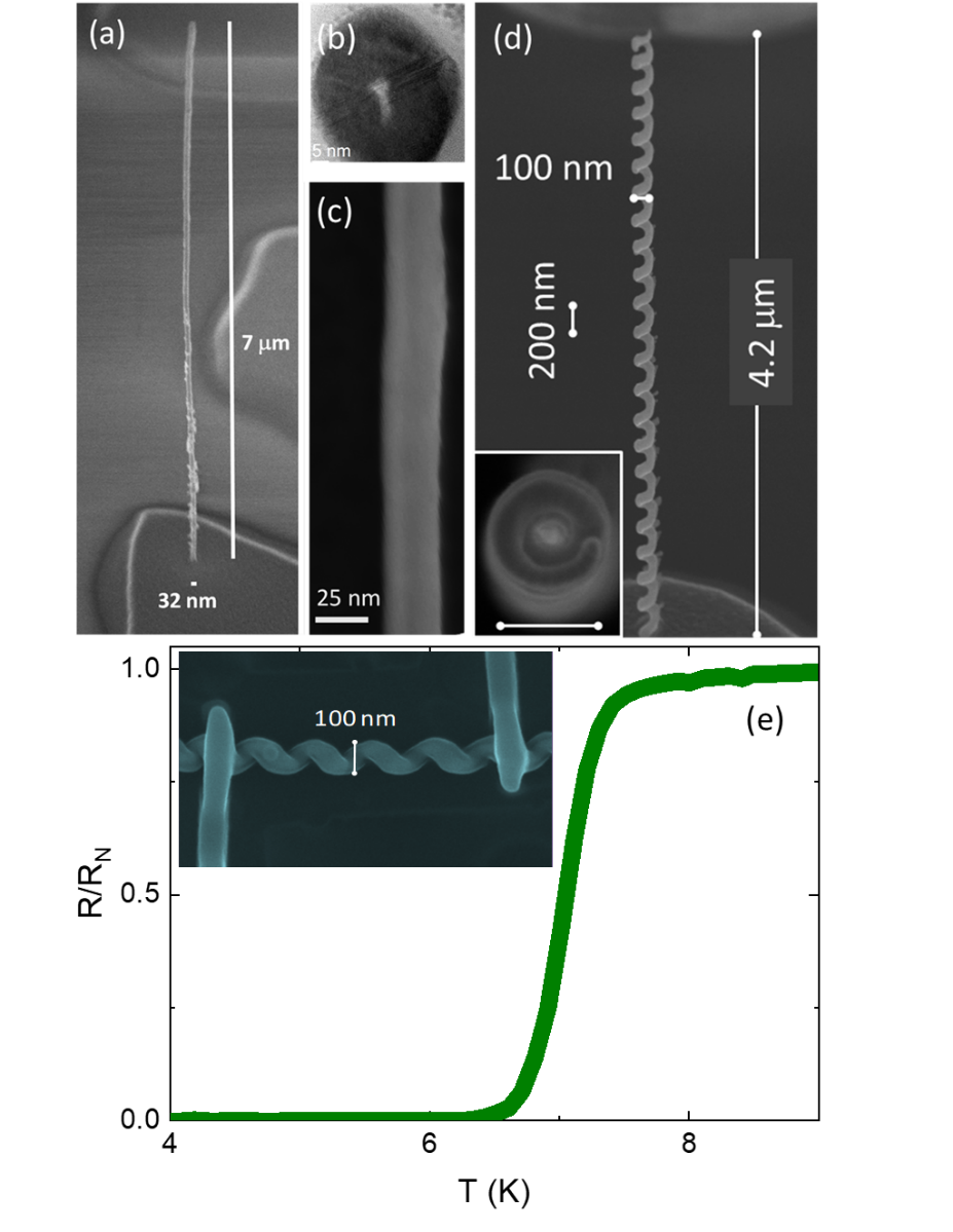
These nanostructures exhibit a metallic content of \qty70at.% W and consist of -sized fcc WC1x nanocrystals.
IV.5.3 FIBID nanostructures for mechanics
One of the main advantages of FIBID over standard lithographic techniques is the capability to directly write high aspect ratio structures onto any substrate topography. When it comes to mechanical applications, this allows e.g. placement of dedicated tips onto AFM cantilevers and spring structures into prefabricated mechanical devices.A recent review by Utke et al. [1087] summarizes the mechanical properties of FIBID pillars and springs. All structures were deposited using Ga-FIBID (ion energies mainly , beam currents ). An interesting finding was that the Ga-FIBID pillars tended to grow as core-shell structures. Using the precursor phenanthrene (C14H10), elastic moduli of the hydrogenated carbonaceous material in the core and shell were \qty≈300\giga (stiff core with Ga implantation, low H content) and \qty≈30\giga (soft shell, presumably high H content) [1073, 1074]. Depending on the inner diameter of the core and the thickness of the shell, the elastic modulus of the structure ranges between these boundary values. Metallic pillars with metal contents \qty<40at.% (i.e. below the percolation threshold) have mechanical properties dominated by the co-deposited carbonaceous matrix [1087]. Increasing metal contents yield elastic moduli as follows (metal at.% / elastic modulus normalized to that of pure metal): Fe (21 at.% / 0.4) [1075], Pt (60 at.% / 0.8) [1076], W (80 at.% / 0.4) [1077], SiO2 (95 at.% / 0.8) [1078]. The non-correlation between the metal content and elastic modulus of the pillars may be due to Ga implantation, which softens the metals. Furthermore, the carbonaceous matrix stiffens or softens the pillar depending on its sp2 vs. sp3 hybridization ratio and its hydrogen content.
So far, \Acfibid is typically not used to fabricate high aspect ratio scanning probe tips, in contrast to FEBID; see review by Plank et al. [1088]. This can be attributed to the strong tendency of the Ga ions to mill the cantilever substrate rather than induce tip (pillar) growth. Implantation of Ga into the cantilever can also be a problem. Here, the enhancement of deposition yields using pulsed irradiation can bring benefit [431]. Since the sputter yield of He ions is much lower, He-FIBID also shows promise in this area, and has been used for the fabrication of 3D hammerhead AFM probes [1072]. In the case of strain sensors based on piezoresistive granular material, FEBID is also still the method of choice [1089]. However, here too changing to He or another light ion species for FIBID could prove fruitful [434].
IV.5.4 FIBID nanostructures for photonics and plasmonics
fibid is also a powerful nanofabrication tool for the exploration of novel optical properties thanks to its unique design flexibility [302, 1090, 1091]. The site specific and local nature of FIBID allows the growth of photonic structures on different material substrates [1092], providing a path to the fabrication of a number of optical elements, such as chiral optical antennae [1064, 1069], Fresnel lenses [566], and nanosensors [1071]. Combined with large area laser interference lithography to fabricate a large area photonic crystal, FIBID has been used to define defects to form a multimode waveguide [1063].
Under optimized parameter conditions, it is possible to evolve planar structures along the third dimension, thus manufacturing free-standing nanostructures with more exotic optical properties. For example, 3D chiral nano-helices, prototyped by FIBID, have shown tunable chiroptical response at optical frequencies [1065, 1066], (Figure 25(a)), been used as subwavelength circular polarization optics (Figure 25(b)) [1069], exploited in compact and miniaturized high-sensitivity biosensors [1071], and integrated onto the apex of background-free and broadband chiroptical probes [1068].
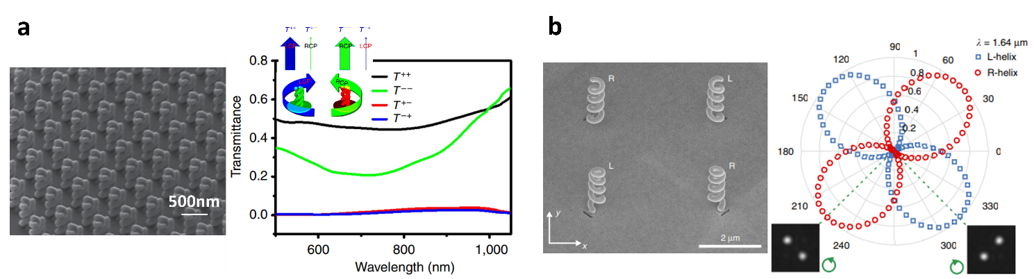
The wide range of available gas precursors enables the deposition of metal and dielectric materials that can be applied in the emerging field of photonic resonant nanostructures [431]. Pure and homogeneous compositions are, however, intrinsically hindered due to various aspects of the deposition process, such as incomplete dissociation of the precursor molecules and the residual contamination from hydrocarbons present in the vacuum chamber, both of which result in carbon content in the nanostructure, and the inevitability of implanted ions, which cause absorption losses, and in some cases, material damage. As a result, FIBID materials exhibit either a nanocrystalline composite structure [1025, 1023, 1093] or a core/shell architecture, depending on the precursor properties and on the FIB irradiation conditions [1094]. Apart from purification approaches, which have mostly been used for FEBID (and which might alter the nanostructure shape and dimensions) [1095, 1096, 1097, 1098], or reduced implantation effects due to enhanced deposition yields (which require the employment of cryo-FIBID [1051, 294, 295]), other promising strategies to control the final optical response are post-processing coating methods. In the case of complex 3D shapes, conformal coverage can be obtained by combining FIBID with glancing angle deposition of metals [1069, 1068], cyclic voltammetry coating of polymers [1071] and atomic layer deposition of oxides [1099]. Also, the core-shell architecture (resulting from the scattering of Ga into a lower molecular weight matrix) can be controlled to engineer specific optical effects [1100, 1101]. Other approaches may emerge from the exploitation of other ion beam sources for FIBID, such as LMAIS [47, 1102].
IV.5.5 Outlook
Focused ion beams are a flexible and versatile tool for gas-assisted processing, but so far have been much less used than focused electron beams for this purpose. The reason for this may be the dominance of Ga-FIB, whereby Ga ions are not only implanted into the deposits but can also cause significant physical sputtering and trigger undesirable chemical and physical side effects. In addition, there is still no precursor development specifically for FIBID. Deposition with ions can in fact deliver purer and denser materials due to their much higher mass compared to electrons. In this regard, ion beams from noble gases, which are chemically inert, are of particular interest. While several studies have already presented promising results for \Acfibid using He and Ne ions (cf. Table 8), \Acfibid using beams of Ar, Kr or Xe ions from PFIBs has not yet been reported and should be explored.
IV.6 Novel and unconventional approaches in FIB processing
Apart from removing or depositing material, introducing dopants or creating defects, the interaction between ions and solids can be used to change materials chemically or morphologically. Such ‘non-standard’ approaches include FIB-induced cross-linking or dissociation in different types of organic and metal-organic surface layers and also the triggering of self-organization processes. Furthermore, ‘standard’ FIB procedures can be combined with other nano- and microfabrication techniques to mitigate specific limitations and broaden applicability.
IV.6.1 Resist patterning by FIB
In resist based lithography the goal is to induce a chemical change in the exposed resist layer to render it either soluble (positive tone resist) or insoluble (negative tone resist) to the subsequent development step. Resist based nanopatterning techniques using photons (optical lithography) and electrons (EBL) are common in industry, with the main properties being, respectively, high throughput and high resolution [1103]. With the aim of improving the throughput of EBL while maintaining a high resolution, pioneering studies demonstrated the use of Ga-FIB to expose resists [39, 1104, 1105, 1106]. Ions have the advantage over electrons that due to their mass they do not induce backscattering from the underlying substrate and therefore reduce unintended exposure of neighboring pixels (known as the proximity effect). For example, line widths of less than \qty100nm and a sensitivity of \qty8e11ions\per\centi\squared were found using a commercial negative resist and \qty30kV Ga-FIB irradiation [1105]. Line widths of less than \qty30nm and a sensitivity of \qty1e13ions\per\centi\squared were achieved using the positive poly(methyl methacrylate) (PMMA) resist and \qty50kV Ga-FIB irradiation [1104]. Furthermore, using \qty50kV Ga-FIB irradiation of the negative poly(phenyl silsesquioxane) (PPSQ) resist, sub-\qty100nm tunneling tip structures were fabricated for a sensing device [1106]. Yet the drawbacks of Ga-FIB include sputtering of the resist and a relatively large beam spot size (several nanometers) with significant beam tails. Compared to the significant developments of EBL over the following years, these drawbacks hampered further use of FIBs for resist exposure until the advent of the HIM. \Achibl combines a smaller probe size with a low sputter yield, high resist sensitivity, and a reduced proximity effect [1107].
First studies published in 2009 already highlighted the potential of helium ion beam lithography (HIBL) for sub-10 nm patterning [1108, 1109]. In both cases, hydrogen silsesquioxane (HSQ) negative resist was used. An ion dose of only \qty31\micro\per\centi\squared was required for complete exposure [1109] (see Fig. 26(c)).

Compared to EBL using the same resist, the dose required for HIBL is lower by a factor of four. HIBL can therefore simultaneously provide a similar resolution to EBL with a better throughput. HIBL with HSQ has also been employed to fabricate a hard mask for subsequent metal etching [1110] (Fig. 26(a)) and as a mold for nanoimprint [1111] (Fig. 26(b)).
The 3D nanofabrication of complex crosslinked HSQ nanostructures, such as embedded nanochannels and suspended grids, was demonstrated using different exposure configurations [1112]. Furthermore, due to the large depth of field of HIBL, large-area dense patterns have been achieved on HSQ as well as exposures on tilted surfaces [1113]. The use of the Ne-FIB for HSQ exposure has proven interesting, providing a trade-off between high resolution and dose efficiency [1114].
HIBL using other resists has also been investigated. For example, sub-\qty10nm resolution has been obtained on a fullerene based resist using a dose of \qty40\micro\per\centi\squared, which is three orders of magnitude lower than that of a similar process using EBL [1115]. Likewise, sub-\qty10nm resolution was achieved on an alumina-based resist, and \qty10nm lines (with an aspect ratio of 1:10) were then transferred to Si by means of low-bias reactive ion etching [1116]. HIBL using a new metalorganic negative resist, Cr8F8(pivalate)16, has been shown to enable sub-\qty10nm resolution patterning using a line irradiation dose of \qty20pC/cm (three orders of magnitude lower compared to EBL), demonstrated for Si and W substrates with good resistance to subsequent dry etching [1117]. New hybrid organic-inorganic resists based on Ni have also been demonstrated to perform well in HIBL, requiring an irradiation dose of \qty22\micro/cm^2, producing sub-\qty10nm resolution with low line edge/width roughness [1118]. Notably, HIBL using a new resist composed of a radiation-sensitive monomer (MAPDST) with an organic functionality (TIPMA) only requires a very low exposure dose of \qty6\micro/cm^2 [1119]. The exposure of PMMA to He and heavier ions has also been investigated [1120].
Additionally, HIBL has shown good performance in combination with lift-off processes, in particular with Au, which has been used to fabricate plasmonic nanoantennae [1121]. A different approach consists of the direct He- and Ne-FIB milling of HSQ or PMMA resists that have been previously patterned using standard EBL [1122]. This can for instance be used for pattern repair. HIBL has also been proposed as a method for the (pre-) screening of EUV resists to help evaluate their performance [1123].
In general, it can be stated that HIBL is very promising for high-resolution resist based nanopatterning due to the low proximity effect and the lower ion dose required in comparison with EBL. Thus broader use of HIBL in the coming years can be anticipated. More detailed discussions on this topic can be found in previous review articles [1124, 1107, 471].
IV.6.2 Cryo-FIBID
In the past, it was found that electron or ion irradiation of Sn-based precursors condensed on a substrate at \qty120K produced deposits with metallic behaviour [1125]. The topic was recently revived through the use of Ga-FIB to dissociate condensed W(CO)6 precursor at \qty-100, giving rise to WC nanodeposits that exhibit metallic resistivity [1051]. The particular advantage of the cryo method is the low ion dose required (600 times lower) compared to the standard Ga-FIBID process at room temperature. The new technique, coined cryo-FIBID, requires that the thickness of the condensed precursor layer is comparable to the ion penetration depth, so that the deposit does not lift off when heated back to room temperature [294, 295]. Cryo-FIBID has also been carried out using the precursor MeCpPtMe3 [296], although the resulting PtC deposits were less conductive than their WC counterparts.
So far, the best cryo-FIBID results have been achieved using the precursor Co2(CO)8 [297]. In this case, the Ga ion dose required is only \qty15\micro\per\centi\squared and the obtained metallic resistivity is low (\qty200\micro\centi). Using cryo-FIBID it is thus possible to write electrical contacts with greater efficiency directly onto a micro-/nanostructure, as outlined in Fig. 27(a–d), and applied to grow electrical contacts onto materials such as graphene, as shown in Figure 27(e).

Conveniently, the need for a cryogenic module in order to decrease the substrate temperature for the cryo-FIBID experiment can be circumvented by means of a cheap, vibration-free and compact thermoelectric plate. Recent process optimization along these lines has enabled thermoelectric cooling to \qty-60 for cryo-FIBID with W(CO)6 [1126]. The resistivity of the deposits (\qty620\micro\centi), is even lower than that obtained for cryo-FIBID performed at \qty-100. Cooling via the thermoelectric plate method thus provides a promising route for the widespread use of cryo-FIBID in any FIB chamber. Further cryo-FIBID studies will benefit from ongoing process optimization of the thermoelectric cooling method and from the use of alternative and novel precursors for metallic deposits in condensed form [1127, 1080]. Future application of cryo-FIBID to directly and efficiently create electrical contacts onto 2D [297] and other ion-sensitive materials is to be expected.
IV.6.3 FIB irradiation of metalorganic spin-coated layers
Although spin-coated layers such as resists are typically used as sacrificial material in a multi-step patterning process, it had also been proposed that metalorganic spin-coated layers could be directly patterned using ion irradiation, producing metallic structures based on Pd [514, 1128], Ir [1129] and Au [1130]. However, post-annealing treatments were required to achieve the desired metallic resistivity values, which limited interest in this approach. Similarly, electron irradiation of Pd-based spin-coated layers has been used to create nanopatterned structures, but there too, a post-annealing step is required to achieve metallic resistivity [1131]. However, recent process optimization using Pd based spin-coated layers in combination with either focused electron [1132] or focused ion irradiation [1133] has led to the development of an efficient process that allows the direct patterning of metallic micro- and nanostructures at the wafer level without the need for annealing. Due to the simplicity of the process, together with its high resolution and scalability, it is tempting to foresee its wide application for the patterning of electrical contacts or other conductive structures in nanoelectronics.
IV.6.4 FIB induced mass transport
Many effects known from broad beam irradiation studies are also observed during FIB processing. This includes the observation of ion hammering and the viscous flow of nanostructures under FIB irradiation [1134, 361]. Spatially resolved ion beam mixing using FIB with subsequent rapid thermal annealing has been used to create nanometer sized Si crystals at freely defined positions for single-electron transistor applications [410]. Furthermore, localized ion beam induced growth of nanostructures is often observed and can result in epitaxial overgrowth [406] or the selective growth of nanopillars [1134]. An overview of these and other effects related to mass transport along surfaces or between layers, including variations such as atomic mixing, can be found in Allen [471].
A further example of such irradiation effects is the formation of self-organized patterns (such as “ripples”) on the surface of semiconductors, depending on the angle of incidence and the energy of the ions. The broad beam process using noble gas ions is qualitatively understood with mass redistribution playing an important role [1135, 1136, 1137]. FIB induced self organized pattern formation has mostly been studied for other (mostly metallic) ion species [1138, 1139, 1140, 1141, 1142, 1143, 1144, 1145]. Here, the underlying physics is more complex due to the unavoidable change in stoichiometry of the sample as a result of the high fluence of primary ions. The situation could be simplified by using inert gas ions from GFIS or PFIB. In combination with spatially resolved surface structuring, these mass transport effects have the potential for interesting applications, e.g. controlling the wettability of FIB milled trenches for microfluidic applications. Here, understanding and control of the wavelength of the surface ripples will be key [1146, 1147].
IV.6.5 Hybrid fabrication and heterogeneous integration
Despite the flexibility of FIB based processing, the intrinsically low throughput of the serial technique means that large-scale patterning remains elusive. A way to overcome this limitation is to combine the FIB step with other lithography methods, using the so-called ‘mix and match’ approach. For example, in a method combining FIB patterning with nanoimprint lithography (NIL), HSQ resist was patterned by He-FIB and used as a nanoimprint template after development [1111]. Remarkably, this allowed the transfer of lines with a half-pitch of \qty4nm into the UV-curable nanoimprint resist. Similarly, miniaturized fluidic channels for single molecule analysis consisting of complex, multilevel, multiscale fluidic circuits have been patterned using FIB and photolithography to make a silicon master stamp followed by UV-NIL to fabricate a negative replica that was used as the working stamp to imprint the fluidic devices quickly and with high fidelity [1148]. The fabrication of arrays of complex plasmonic nanostructures has been achieved by combining EBL and Au-FIB, demonstrating both planar and 3D nanostructures with high patterning accuracy over large areas [1102]. In further examples, optical lithography has been combined with FIB milling to allow the fabrication of nanochannels in Si-glass microfluidic chips for studies of ion and molecule transport [1149, 1150] and for the separation of nanoparticles by size exclusion [1151]. FIB techniques have also been combined with other processing methods, offering improved versatility in terms of the material to be processed and reducing total processing times. For example, FIB patterning of molds into Si was applied for subsequent hot-filament CVD growth of diamond nanocone arrays on a free-standing diamond membrane formed after silicon removal [1152]. Similarly, direct patterning of inorganic hardmask layers has been demonstrated using FIB milling and FIBID combined with reactive ion etching, comparing favorably with the much more complex and material-limited resist based lithography techniques that are conventionally used in this area [1153]. Instead of using the hard mask for later etching steps, it can also serve as a sacrificial layer that enables the use of high ion beam currents. For example, milling through a chromium oxide mask about \qty63nm thick provided the same spatial resolution with 100-fold increase in ion beam current (\qty2.6nA instead of \qty26pA). This approach has been used to fabricate Fresnel lenses from silicon dioxide, increasing throughput by a factor of 75 for functionally identical structures [567].
A further promising application is the use of the FIB as a post-processing tool in CMOS chip manufacture. This extends the semiconductor industry’s conventional use of the FIB as a debugging and inspection tool, to the top-down FIB based integration of novel semiconductor circuitry, such as nanometer-scale mechanical devices [1154, 1155]. In connection with new (nano)-electronic materials, such as single walled CNTs, it has also been shown that there is low, amendable damage to electrical circuits when a FIB patterning process is implemented after fabrication of the basic structure [1156, 1157].
IV.6.6 Outlook
In terms of applications, machining using FIBs goes far beyond a purely top-down approach, since it can also be used to trigger various chemical and physical processes, and combined with various other micro-/nanofabrication techniques. Device fabrication based on unconventional processing steps, as well as unique combinations or alternative advanced sequences, may further gain in importance since these methods can mitigate typical limitations in either FIB processing or the other fabrication techniques. It is hard to foresee in which way such unconventional processing techniques will develop, but they will certainly benefit from progress made in many other areas, e.g. new insights into ion induced chemical processes, novel precursor materials, as well as novel ion species and newly accessible energy ranges.
V Roadmap
Focused ion beams can be employed as an all-in-one tool for studying and modifying matter down to the nanoscale. A showcase example of these diverse applications is given by the He-FIB, which enables imaging of corona virus particles and the fabrication of Josephson tunnel junctions (and much in between), all using the same instrument.
Building on the previous sections of this article describing the current state of the art of FIB instrumentation, theory and applications, we can now ask where to go next with FIB technology. There are many avenues to pursue, so the answer to this question is multifaceted and complex. The present section is devoted to trying to answer this question in some detail.
Figure 28 provides an overview of the fields that drive various FIB techniques and the resulting challenges and demands for the further development of instrumentation, hardware/software interfaces, accessories, process modeling, and fundamental understanding.

As the figure outlines, all of these required developments are driven by established or newly emerging research fields that use the FIB as a tool for any or all of the following: localized and comprehensive analytics, material modification, and advanced device fabrication.
To account for the complexity of the situation without getting buried in details, this section is organized around the important future developments that we have identified as necessary in order to meet the needs of the drivers. Each driver requires different FIB techniques, brings its own challenges, and demands different actions to move forward. In the following, a short description of these drivers is given and an evaluation of the needs of the user community is then presented. The latter is based on the results of a survey completed by over 50 scientists from across all FIB research fields. The developments necessary for future progress are then derived and described in terms of their challenges and overall potential.
V.1 Drivers for future applications
The drivers for FIB technologies span a wide range of fields in science and technology. Currently, the semiconductor industry is the largest driver, demanding process automation, modeling and the analysis of big data.
In general, the drivers can be separated into two interrelated areas. In the first, the FIB is mainly used for analytical purposes, providing access to a wealth of structural information and physical properties. In the second, the FIB enables rapid, flexible device prototyping and stimulates novel device development. In both of these areas material modification using the FIB is key, be it to enable a particular form or analysis, or to fabricate novel structures and devices.
A leading example of FIB based analysis is in the life sciences, where it often involves large-volume 3D tomographic analysis of cells and tissues under cryogenic conditions (see Section IV.3.3). This drives the need for increased processing speed, advanced cryo capabilities and automation. One potential way to increase throughput is through cryo plasma-FIB milling, which enables faster removal of bulk material, as discussed in Section IV.4. However, cryogenic processing is not straightforward and is further complicated by insufficient vacuum levels in the sample chamber of current dual beam instruments. A better vacuum, as has been demonstrated in the past, can reduce contamination, and in the case of cryo-FIB, can also lead to less water condensation on the target structure.
In both the life sciences and materials science, as well as in environmental research, FIB techniques such as cross sectioning, tomography and sample fabrication (e.g. for TEM and APT studies, or ex-situ characterization of physical properties) have become established standards that would now benefit from powerful process automation. Materials science in particular can benefit from other ion types, such as ions from noble gas elements that (a) may not accumulate in the material, since they can either pass right through if the sample is thin enough or leave by out-diffusion, and (b) will not undergo chemical reactions. This also applies to radiation hardness testing of materials, where FIB is used as a means to locally mimic the effects of a plasma or solar radiation. Increasingly, cryo-FIB techniques are also being applied to beam-sensitive samples, such as novel battery materials that are relevant for energy-technology applications, which also calls for the cryo-related developments mentioned above. In the case of multimodal imaging approaches and the identification of target areas for e.g. TEM lamella preparation, workflows are currently hindered by the very different contrast mechanisms in e.g. the fluorescence light microscope versus SEM. Addressing this will require improved correlative techniques as well as more advanced data management and analysis (cf. Section II.6).
In a broader context, FIB research into quantum and 2D materials, as well as other novel materials, can largely be subsumed under materials science, but should be recognized as drivers of “non-conventional” FIB techniques in their own right. For example, the growing interest in quantum materials is driving the need for rapid and high-precision patterning of large 3D structures from novel materials. This could be achieved by combining process modeling with an easy-to-use interface for 3D shape definition and calculation of the required beam and patterning parameters. In addition, chemical functionalities can be integrated into patterning through the development of novel ion sources; oxygen in particular is an important tuning parameter for the electronic structure of many quantum materials.
At a more fundamental level, the maskless approach of FIB processing renders it an ideal technique for the precise creation of defects at the exact location where they are needed. This is driven by applications in quantum technology, where defects in an otherwise perfect crystal can act as quantum emitters or, if they carry spin information, as qubits.
On the theoretical side, the creation of specific defects and especially single ion implantation (SII) require a deeper understanding of the mechanisms of defect formation and the evolution of the defect’s local environment, which in turn determines the physical properties. Such challenges can be addressed by modeling at different levels of sophistication, as described in Section III.
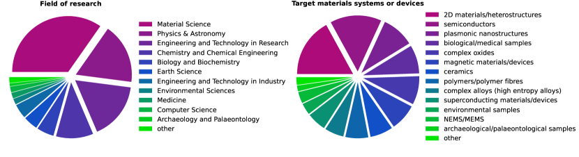
In terms of instrumentation, a key technological challenge for quantum applications is to be able to place individual ions in a (quasi-)deterministic manner and detect them with very high efficiency. Certain defect types may require the implantation of a specific ion for which stable ion sources still need to be developed. The implantation depth is controlled by the mass and kinetic energy of the incident ion, and in order to reduce dephasing, quantum emitters in photonic chip architectures are usually desired to have a depth of \qtyrange10100nm beneath the surface. As such, the ion energy ranges of tens of keV that are currently available are mostly well suited. However, in the case of spatially resolved heavy element implantation, a higher primary beam energy would be required, which poses challenges for the power supplies and for electrical isolation in the ion optical column. If instead non-native atoms are to be implanted into 2D materials, e.g. for high resolution flexible area doping, lower energies are needed. In this context, low energy means less than \qty100eV to ensure a significant number of replacement collisions in which the ion exchanges position with a target atom and the latter is removed from the 2D material [376]. Methods to reduce the primary energy of the beam include using deceleration lenses in the final stage of the beam focusing or implementing reverse sample biasing (see also Section V.3). For the detection of the transiting primary ion itself or the resulting interaction with the substrate, various approaches are under development (see the Outlook of Section IV.2).
Another strong driver for FIB technologies are micro-electro-mechanical systems (MEMS)/ nano-electro-mechanical systems (NEMS) and microfluidic devices, which are ubiquitous in our modern world, be it in sensors, displays, printers, transducers or microphones. Such devices often combine various active and passive components consisting of electronic and moving parts, and therefore typically rely on a whole chain of thin film lithographic, deposition and etching techniques. However, these fabrication techniques require that the devices are built up layer by layer. As such, true 3D geometries are difficult to achieve.
FIB processing by milling and deposition, on the other hand, enables the flexible fabrication of complex multi-level geometric structures and smooth 3D shapes, as it permits direct top-down and bottom-up structuring in the same instrument. What has limited the default implementation of FIB technologies in device manufacturing thus far is the slow processing speed of the inherently serial process. Here, the availability of a multibeam system comprising thousands of individually addressable focused beams would represent a major leap forward (see also Section II.2 ).
V.2 The generic needs of the community
FIB systems have become a standard in scientific research and industrial processing, but the market is still heavily dominated by the Ga-FIB. While Ga represents a good compromise between spatial resolution and sputtering yield for many material systems, other applications require different beam parameters and/or suffer from Ga contamination. In our survey, the participants were therefore asked in which areas they conduct research and upon which material systems and/or devices they focus. The corresponding results and percentages thus reflect the perspectives of this particular group of users. Figure 29 shows that material science, physics and engineering are the most prominent research areas in the FIB community surveyed. Fields such as biology, medicine and earth science may be underrepresented in these statistics, since fewer scientists from those areas participated in the survey. It would be interesting to repeat the survey with a larger number of participants from a wider range of fields in order to be more statistically representative. The material systems most commonly studied by the respondents are 2D materials and semiconductors, followed by various other systems including biological samples, ceramics, polymers and environmental samples. This reflects current research trends, but also underscores the universality of the FIB as a tool for modifying matter at the nanoscale.

The typical problems encountered by the FIB users participating in our survey (see Fig. 30) show a clear trend, with surface damage, unwanted implantation/doping and contamination being the most dominant problems. This last point on contamination is mostly related to the typical vacuum operating range of around mbar and the associated residual gases in the vacuum chamber. In this pressure range, a monolayer of molecules still forms on the sample roughly every second, and with a typical water content of around 60 in the residual gas, most surfaces will also be covered with a double layer of water molecules. The hydrocarbons from the residual gas are also decomposed by the ion beam and, depending on the ratio of the sputtering to deposition yield, can form a carbonaceous layer on the sample. Especially in the case of FIB processing with light ions, even a small amount of contamination can result in greatly reduced net sputtering rates or in the extreme, net contamination deposition. Generally, both water and hydrocarbons can add various, mostly unwanted, chemical reaction channels (cf. Section IV.5.1). Here, a significant improvement of the vacuum level toward UHV would be an important development. Since some of the contamination is introduced with the sample itself, a dedicated load lock for plasma cleaning of samples prior to FIB processing would be an ideal complement. Other unwanted chemical side-effects may occur when the ion interacts inside the sample and can be mitigated using inert ion species. However, unwanted physical side-effects such as interlayer mixing or dealloying are difficult to avoid as this would require a significant reduction in primary ion energies; in the shorter term these effects can be better addressed through process modeling (cf. Sections III.1 and III.2).
Problems with long patterning times are either due to beam currents not being high enough or to stability issues of the system. PFIB columns address the first issue by proving higher beam currents, but at the expense of a larger probe size. One especially intriguing way of increasing processing speed and thereby reducing patterning times would be the implementation of a multibeam system. Thousands of parallel beams could in principle be available while maintaining small probe sizes (cf. Section II.2). System stability is mainly limited by the use of mechanical stages, which suffer from drift over time and from inaccuracies in positioning. In principle, laser interferometric stages solve this problem. However, since most FIB systems use a tilted column, the sample must also be tilted in order to allow FIB processing under normal incidence. Thus novel system designs with a vertical FIB column are of great value. Finally, instabilities in the beam current itself (more of a problem for some of the novel ion sources) can also limit patterning performance, so the development of novel and stable emitters is needed (cf. Section II.1).
Interestingly, the survey answers to questions about desired spatial resolution, milling depths, deposition thicknesses and beam energy ranges more or less correspond to what is currently technologically possible. This makes sense, in that users often aim for what is feasible with their instruments. Only a few users were interested in depositing single molecules or removing/implanting single atoms. Currently, such approaches are beyond the technological capabilities of commercial systems and would require substantial developments. However, with these developments the impact on areas such as quantum technology research would be substantial.
V.3 Important future developments
Having discussed the needs and wants of the FIB research community in terms of future applications and user experiences, we now turn to specific technologies that need to be developed. For this purpose, Figure 28 has been divided into subplots based on different groups of to-do items. This allows us to trace the impact that certain developments will have on specific challenges, to explore the techniques that are then enabled, and ultimately link back to the drivers.
V.3.1 Ion beam generation and transport
Figure 31 displays the required developments (i.e. to-do items) and the associated challenges, techniques and drivers in the area of next-generation FIB sources and ion beam transport. Specific needs for novel ion sources, ion optics for both low and high energy beams, and fast beam control/blanking have been identified.

Novel source types including single isotope sources
A key area requiring development concerns novel ion sources, in particular, high brightness and light element sources, which are crucial for high-resolution imaging and nanostructuring applications. Here, further development of GFIS based sources to operate with gases other than He, Ne, and N2 is desired. The first steps in this direction have already been taken by various researchers testing GFIS based emission of H [1158], Xe [60], and Kr [61]. However, the heavier noble gas elements have numerous isotopes, sometimes in nearly equal proportions; if the ion optical column is not well shielded from magnetic fields, this can affect spatial resolution, since magnetic fields present in the column can split the ion beam according to the mass of the isotopes. Solutions to this problem, other than shielding, include the addition of a Wien filter. Again, these developments will require new ion optical columns that can reduce or correct the aberration induced by the Wien filter. Alternatively, isotopically pure source gases can be used, similar to the already successful implemention of isotopically pure source materials by manufacturers of Ga-LMIS and AuGeSi-LMAIS. Further LMAIS single isotope sources might also be of interest in the context of SII [293, 194, 829, 835], local isotope enrichment [766] and for a wide range of other applications e.g. SIMS, also in combination with reactive gas flooding [123, 125, 1001, 992]. The GaBiLi-source [1159, 46], for example, provides heavy Bi atoms and small Bi clusters for milling, and a reactive Li ion beam for analysis by SIMS. With the LMAIS, switching between ion beams for these different species is fast (only takes a few seconds) and can be automated. For the future, new alloy concepts that include heavier reactive species are desired; to date only Au-Si, Au-Ge, Au-Ge-Si and Ga-Bi-Li LMAIS are commercially available.
Ion sources for heavy ions are desirable for applications such as SIMS in order to increase sputter yields and also for device debugging in the semiconductor industry, where the shorter penetration depth of the heavier ion is an advantage. Furthermore, ions from group 1 and group 17 in the periodic table are of interest due to their chemical reactivity, which enhances sputter yields. While successful attempts have been made in the past with group 1 elements [31, 46, 29, 1160], efforts for the development of sources based on group 17 elements such as fluorine or iodine are more limited. A possible approach for reactive ion sources using group 17 elements could be the ILIS if implementing the appropriate salts [54]. Such ILIS prototypes have been developed, but they did not yet enter the market. One of the intrinsic issues when operating an ILIS is the need to switch the polarity of the extracted ion beam in order to keep the source composition in balance. While this is usually considered a nuisance it can become an advantage, since by using clever chemistry, ion beams suitable for performing SIMS with both polarities could be extracted. However, collateral damage by the reactive ions to the ion optical elements needs to be considered and avoided as much as possible. We note that the first commercial FIB systems combining reactive ion species with SIMS are currently entering the market [977, 1161].
With regard to source brightness, the recently developed MOTIS/LoTIS have been shown to achieve high brightness for a number of ion types [31, 29, 1160]. Furthermore, fundamentally new concepts based on e.g. insulator-on-conductor ion sources [1162] and other ideas that currently have a very low technology readiness level (TRL) may also have potential for application as high brightness sources, since they partially exploit similar concepts to the GFIS technology.
An aspect that is becoming more and more important for users is instrument uptime, which can be increased by minimizing source maintenance needs. For example, LMIS and LMAIS lifetimes could be increased by increasing the reservoir size of the liquid metal/alloy. The lifetimes of the apertures could be increased by adjusting the material and thickness of the aperture strip, as well as the number of apertures incorporated.
Ion optics for low and high energy ion beams
Access to low energy ion beams (\qty<1keV) is becoming increasingly important for a range of FIB applications in which the penetration depth and ion straggle in the material must be minimized. However, the transport of a low-energy beam without sacrificing on resolution is a challenge. This is mainly due to chromatic aberrations (see also Section II.2). To address this issue, specialized beam optics such as energy filters and chromatic aberration correctors are needed, which are in general complicated to produce, align and tune [1163] thus posing extra challenges for system automation. Low-energy beams also pose challenges in terms of the stability and precision of the associated electronics.
Key areas where low-energy high-resolution FIBs will bring benefit are in FIB based debugging and mask repair in the semiconductor industry [507], where minimized ion penetration and thus minimal damage to underlying layers and structures is required. If these low-energy FIBs employ heavy ions, the beam-sample interactions can be confined even more closely to the surface. A further application that requires ultra-low energy beams (down to a few tens of eV) is the controlled and spatially-resolved doping of 2D materials or the ion-beam induced modification of surfaces (see Section III.1). For the latter, the energy spread of the ions emitted from the source must be exceptionally small to begin with, smaller even than the LoTIS and GFIS can deliver. Indeed, in order to reduce chromatic aberrations for all of the above, it makes sense to start with new types of ion sources that have a reduced energy spread and then employ subsequent beam elements for chromatic aberration correction accordingly.
For other applications, higher energy beams are required, such as for the deep placement of (heavy) atoms for quantum technology applications, and for applications requiring even higher spatial resolution. Since the ion collision cascade expands the FIB beam in the material and most damage occurs at the end (cf. again Section III.1), it may be useful to use high energies for devices based on (potentially suspended) thin films. The target defects are then generated close to the surface with high spatial precision, but low yield, and the beam damage occurs spatially separated from this in the substrate (or not at all in the case of suspended membranes). While the technological challenges for increasing the beam energy are moderate, the increased size of the required electrical isolation and power supplies will actually limit the achievable resolution, since they may act as additional noise sources.
Fast beam control and blanking
Standard beam blankers installed on FIB instruments typically achieve blanking times (known as rise times) on the order of \qtyrange20100ns. However, for a number of applications, rise times below \qty10ns are desirable and have been demonstrated in isolated cases [120]. Applications requiring faster blanking times include resist patterning, high-end FIBID and SII, in all cases to avoid unintentional exposure.
Another need for specialized beam blanking arises from the fact that ion beam sources typically also create a certain fraction of neutrals in the beam, which is generally unwanted. These neutrals result from charge exchange collisions between energetic ions and neutral gas atoms. The latter are generally present due to insufficient vacuum at the source and in the ion optical column, and in the case of the GFIS, as a direct result of the gas based source technology. In the case of the GFIS, \qty0.29 He0 have been reported under conditions used for medium resolution imaging and for TOF-SIMS (\qty6.3e-6mbar He pressure, \qty20\micro aperture) [1164]. However, these numbers depend heavily on the gas pressure and aperture used. Since neutral species are not influenced by electric or magnetic fields and thus cannot be deflected away using ion optical elements or the standard electrostatic blankers, they can result in broad background exposure, especially in the case of long FIB processing times. This is detrimental in applications concerned with few or single-ion impacts at specific target locations, which often also involve high-dose irradiation (and hence even more unwanted neutrals reaching the sample) to make fiducial markers for subsequent correlative analysis. In order to eliminate the neutral beam, a physical obstacle can be introduced into the central portion of the column, which only the ions can bypass by means of a series of electrostatic deflectors. This is known as a chicane blanker. Similar solutions, such as a curved column, could also be explored but come with their own challenges.
V.3.2 Accessories and complementary instrumentation
In Fig. 32, the required developments related to new accessories (add-ons) for FIBs and complementary instrumentation are outlined. These to-do items can be broken down into categories focused on ion induced chemistry, adaptable sample environments and analytical add-ons.

Ion induced chemistry
Applications using FIBID, gas-assisted etching, and resist-based lithography could all be greatly enhanced by the development of more advanced modeling tools, new gaseous precursors and new resists.
In the case of FIBID, new precursor chemistries that enable higher deposit purity (e.g. for plasmonic applications) and superior resistivity (e.g. for circuit edit applications) are needed. The prerequisite for the development of these precursors is a deeper understanding of the ion-molecule reactions that occur during the deposition process [431]. For high-purity metallic deposits, the precursor molecule will ideally be fully decomposed so that only the desired metal component is deposited and the ligand fragments are pumped away. Similarly, in the case of gas-assisted etching, the precursor molecules should undergo ligand loss to generate empty coordination sites that bind with the substrate to enhance the rate of removal of substrate atoms without forming a residue of nonvolatile reaction products. Once the fundamentals of beam induced chemical reactions are better understood (including aspects such as the effect of beam induced heating), researchers will be better poised to develop simulation tools to enable the prediction and design of more complex deposition and etching scenarios. The development of these simulation tools will also rely on input from systematic parameter optimization, where automated beam control and data analysis will play a key role.
A common but generally undesired effect from ion induced chemistry is the deposition of a thin carbon film over ion-irradiated regions, arising due to residual hydrocarbon species present on the sample surface and in the microscope chamber [890]. This effect can be minimized by e.g. plasma cleaning samples before loading into the microscope or working in UHV. Other unwanted beam induced effects that can occur during intentional deposition processes include implantation of the ions themselves into the deposit during the growth process, or concurrent milling of the deposit. To minimize these effects, it is desirable to increase the deposition rate, so that a lower total ion dose is needed for the process. Recently it has been shown that cryogenic cooling of the substrate is one way to increase deposition rates, which could be investigated further [1051]. However, it is worth mentioning at least one application where a balance between deposition and concurrent milling by the primary ion beam is actually desired, namely the formation of high-aspect-ratio hollow nanopillar deposits with unique electronic properties using He-FIBID [1038]. Overall, fine control over the rate of deposition should prove highly beneficial for future applications.
For resist based lithography, further development of resists specifically for lithography using ion beams is needed. It has already been shown that resists tend to be much more sensitive to ions compared to electrons, but so far most resist development has still been for EBL. In order to optimize resists for lithography using different ion species, a deeper understanding of the ion-resist interaction process is required [1120]. Consequently, the full potential of FIB resist lithography has yet to be realized, even though HIBL has already demonstrated high resolution patterning with dramatically reduced proximity effects compared with EBL [1109, 1108].
Adapted sample environments
In electron microscopy, sample environments are now routinely adapted through the use of liquid cells that separate e.g. chemical reagents, from the surrounding vacuum in the chamber. This principle does not readily translate to the FIB, since the typically used Ga ions can easily damage the cell membrane by sputtering and also suffer from limited penetration depths. Accordingly, only He-FIB has been used in a prototype liquid cell [1165], because He ions combine negligible sputtering of the cell membrane with a sufficient penetration depth to reach the reaction volume. In contrast, heating of samples during FIB processing has been used for decades, including more recently for the reduction of ion beam induced amorphization and blistering during He- and Ne-FIB processing. Quasi-local heating with an infrared laser [1166] and homogeneous heating using a heating stage [361] have both been tested. However, the latter approach in particular suffers from sample drift induced by the high thermal mass of the sample heater. Low drift implementations are thus needed that also have lower power requirements in order to protect the rest of the system (e.g. the piezo motors in the stage and ion optical components in the pole piece) from overheating and to allow faster heating ramps [1167]. \Acfibid-related applications could also benefit from new simple heating stages for exploring in-situ annealing of the deposited structures.
Sample cooling can also be of interest to reduce beam damage, de-alloying, and surface microstructure formation, and for applications using FIBID or HIBL. For example, often temperatures slightly below \qty0^∘C are sufficient to prevent the formation of eutectic phases or phase separation. In the same manner, molecular desorption rates may be tuned by either decreasing (or increasing) the temperature by only few tens of Kelvin. Hence, for many experiments with a relatively small temperature range to bridge, Peltier based solutions become possible [1126].
A pressing requirement for substantial cooling comes from biological applications, where cryo-stages and cryo-transfer units have been developed to enable complete cryo workflows (see Section IV.3 for examples). However, due to the stage cooling mechanism and shielding, these systems can suffer from reduced imaging performance as well as limitations regarding sample geometry and compatibility with certain accessories in the FIB chamber. Further development of specialized FIB instruments dedicated to the handling of biological and other sensitive samples is expected. These systems require special load locks for vacuum and/or cryo transfer, and better vacuum conditions in general will result in less condensation on the specimens.
By adding fluorescence light microscopy to a FIB-SEM system, a dedicated and time-efficient platform for the correlative preparation of TEM lamellae for biology, medicine and related fields becomes possible, since well-established fluorescence light microscopy protocols can be used to locate regions of interest for FIB milling in-situ. Indeed, a system including fluorescence light microscopy has recently been demonstrated in a cryo triple-beam configuration [206]. Other implementations for fluorescent light detection either employ an ellipsoidal mirror in conventional Ga and plasma FIB-SEM systems for fluorescence spectroscopy of the atoms sputtered by the ion beam [834], or a full confocal microscope setup integrated into the vacuum chamber of a \qty100kV LMAIS-FIB with a high-precision stage to move between working positions [835].
The latter system demonstrated the in-situ detection of fluorescent light from arrays of optically active defects created by the FIB, thus representing an important step toward realizing the deterministic creation of quantum emitters (cf. Outlook of Section IV.2). For this application, it is of utmost importance to reduce all kinds of residual contamination (fluorescent and chemically active), both on the sample and in the vacuum chamber using UHV chambers and ideally inert sample transfer. Dedicated UHV FIB systems for quantum technology do not yet belong to the commercial standard, but have recently been demonstrated [91, 814].
Novel detectors and analytical add-ons
Quantum technology and therewith the deterministic implantation of ions is one of the main drivers in science and technology today, and correspondingly, there is an urgent need for single ion detection. As outlined in the Outlook of Section IV.2, specialized detectors [193, 194] or specific types of ion sources like a Paul trap [827, 828], can either count the ions that impinge on the sample or measure the ion impact event. The latter can be realized using an on-chip IBIC measurement [199, 829], which can be implemented for many CMOS compatible quantum devices that are not affected if there is an amplifier nearby. For all other quantum devices, truly agnostic SII detectors that detect e.g. SEs will constitute an especially important development. Besides very high detection efficiencies approaching \qty100% [833, 777], appropriate theory support is needed to calculate the expected SE yields. If such detectors are combined with a complementary system that detects device function, e.g. fluorescence [835] associated with single-photon emission from the defects generated, truly deterministic implantation can be realized for an industry-ready commercial platform.
Several types of detection systems exist, which can often be combined to enable the acquisition of unique multimodal data sets. The general trend is toward better spatial resolution in 3D, higher sensitivity (and hence lower detection limits), and better quantification of results. A promising approach in this area is FIB-SIMS. Resolution and sensitivity are directly linked, which must be considered in efforts to improve performance. For example, in the case of GFIS and LoTIS based SIMS, simultaneous improvement in both resolution and sensitivity is not possible, since further reducing the sampling volume renders the number of target species in that volume statistically insignificant. Another analytical approach that is complementary to SIMS uses fluorescence spectroscopy to detect and identify atoms sputtered by the FIB and has been shown to be feasible for certain applications [834].
Various other “classic” ion beam analytical methods have been implemented in FIB instruments or are interesting candidates for future implementations. These include IL [175] and RBS [143], which have been explored by a number of researchers but are not available as commercial solutions. In IL, the luminescence of excited target atoms, defects or recoiled ions is detected using parabolic mirrors and a combination of gratings and lenses to obtain spectral information that allows identification of the emission source. IL was recently demonstrated for semiconductor heterostructures and Li-ion batteries [834], and also has potential for various insulating samples in fields such as geology, mineralogy, biology and medicine, including in nanoparticle research such as nanotoxicology. In contrast, RBS measures the energy and scattering angle of backscattered ions and allows standard-free and depth-resolved elemental analysis. However, RBS in FIB systems has largely been abandoned due to fundamental problems related to the high number of multiple scattering events. Implementing a low energy ion scattering (LEIS) configuration may be a good alternative, as it only measures the energy of the charged particles that are primarily scattered at or close to the sample surface. Nevertheless, due to the low yield of charged scattered particles, high fluences are required to obtain good statistics.
There has been some debate around the potential to use X-rays as a signal for ion induced processes. Some reports indicate that this could indeed be possible [169]. However, in that particular case the observed X-rays were not generated by the interaction of the primary ion beam with the sample. Instead, non-conductive samples became positively charged under ion impact and backscattered ions caused the emission of SEs from components in the chamber. These SEs were then accelerated toward the positively charged sample surface and generated X-ray peaks due to random interactions with the chamber components. It turns out that because the inelastic interactions that are responsible for X-ray generation depend on velocity and not on energy, typical primary beam energies in FIB systems are not sufficient for X-ray production. As stated in Joy et al. [1168], a beam energy of about \qty53MeV for He ions, for example, would be required in order to excite the same X-ray lines as can be obtained using a \qty6keV electron beam. Such high beam energies are out of reach for conventional FIB systems and thus the high-energy PIXE technique remains elusive to FIB.
In contrast to X-ray spectroscopy, the generation and detection of Auger electrons is indeed possible using the beam energies of current FIB systems. Auger electrons are generated due to the creation of core-holes in both the projectile ions and the substrate atoms, thus Auger signals emanate from both colliding particles, resulting in spectra with rich features that can be quantitatively evaluated [166].
Another analytical approach is based on in-situ monitoring of ion beam-induced property changes, such as in-situ electrical measurements to test nanostructured samples or to probe e.g. magnetization via the measurement of a Hall voltage. Various other analytical techniques can also be incorporated into the FIB chamber, including AFM for in-situ surface characterization or a nanoindenter for in-situ mechanical testing. The benefit of performing these techniques in-situ is not only control of the sample environment (e.g. no exposure to air), but also the possibility of real-time imaging (usually with the SEM) enabling immediate quality control of the measurement. For improved implementation of all these approaches, open hard- and software APIs are required.
Further developments that will facilitate work with analytical add-ons are related to the continued integration of sample cleaning options based on UV light or remote plasma, as well as the combination of FIB processing with direct laser milling [1169]. Systems integrating femtosecond laser milling with FIB have recently become available and the associated workflows and possibilities are currently being explored.
V.3.3 Automation and data management
Figure 33 shows the technological developments required in terms of automation and data management. Both of these areas are rapidly growing in importance due to the sheer volume of samples and data.

There is enormous potential to facilitate the daily work of technologists and researchers using recent developments in ML and artificial intelligence. However, the black-box nature of such routines requires awareness and regular cross-checking of both the training data used and the results obtained. In the following, open interfaces for hardware and software, and then needs related to data access and management, are discussed in more detail.
Open hardware and software interfaces
In recent decades, science has increasingly moved toward openness and transparency. Today, this is generally a prerequisite for receiving taxpayer money for scientific research [1170]. The idea of sharing not only raw data (as discussed in the next subsection) but also task-specific developments in terms of machine operation and data analysis holds great potential. Instead of developing isolated solutions specific to particular research groups, which often become obsolete or are lost when the original developers move on, a larger community can maintain and further develop methods much more efficiently. In addition, the overall speed of development is significantly increased, as existing data and tools can be reviewed much more easily before “reinventing the wheel”.
Open access to non-proprietary development is already standard in many scientific fields, but the more technologically sophisticated and commercially valuable scientific work becomes, the more conflicts over intellectual property, licenses and potential patents can arise. Nevertheless, the major FIB instrument manufacturers have recognized the benefits of opening up their machines for modification by the users. Everyday users seek the ultimate in machine performance. Therefore a key resource for driving future developments comes from enabling those users to make the most efficient use of instrument time and gain the most insight from the data generated. The larger the active user community is, the more far-reaching the benefit, which in turn translates to increased sales for the manufacturers even if new technological developments do not have immediate impact on a patent or a price tag. What users need are open hardware interfaces to give them real-time access to detector signals and to enable them to add their own custom components. Even more important is a full-fledged API that allows control of all system parameters accessible in the GUI and ideally all others in developer mode. In this respect, software development on the manufacturer side must be a compromise between the needs of those who require easy-to-use software yet with more limited access, and those who require full access.
For process automation, certain tools are already included in some FIB systems. For example, routines that have already been executed can be stored and modified in a quasi-graphical approach, removing the hurdle of programming in a text-based interface. A key area needing a high degree of automation is in the efficient acquisition of tomographic data sets with imaging based on SE detection, as well as EDS and EBSD. FIB based tomography is particularly used in the life sciences and in environmental research, and increasingly in all branches of materials science, including for battery research and energy conversion. In all cases high precision and repeatability are required.
In the future, automation tools should be complemented by ML algorithms that help with experimental control and real-time data analysis. Integration of an active learning user interface (human in the loop) [1171] for in-operando improvement of the supporting ML algorithms would then allow easy continuous training and thus automatic control and/or optimization of processing based on predefined quality parameters or figures of merit. Such feedback control would also be beneficial for advanced patterning tasks, where modeling-informed pattern generation and optimization could be coupled with FIB-processing in a fully automatic way.
Open software interfaces are also required for data analysis, which varies greatly depending on the application typically requiring a tailored approach. ML-based solutions are similarly very diverse, with application to problems including simple data noise reduction, the broad field of feature recognition and data reduction, super resolution imaging, and full quantification. The integration or linking of different methods and data streams thus needs open interfaces. Therefore, in place of closed all-in-one tools for data analysis and automation, manufacturers should instead provide the infrastructures needed for users to efficiently develop solutions for the broader community.
Data access and management
Likewise, all data generated should be open and ideally FAIR. The acronym FAIR, coined by Wilkinson et al. [1172] in 2016, stands for Findable, Accessible, Interoperable, and Reusable. The FAIR principles have led to global initiatives in all scientific disciplines [1173, 1174, 1175, 1176]. In particular, research areas that generate large amounts of data, such as the life sciences and materials science, are driving the development of data harmonization including a comprehensive set of metadata, ontologies, and workflows that are accessible along with the data [969]. For experimentally-derived data, this includes sample tagging, e.g., with QR codes linked to each resulting data set, along with the corresponding experimental workflows documented in electronic lab journals. One of the biggest challenges with open and FAIR data is the diversity of data sets from different sources. The Novel Materials Discovery (NOMAD) laboratory [1177, 1178] can serve as a blueprint here, as it maintains a collection of data repositories (called oases) for data from virtually all codes in computational materials science.
Several factors are crucial for the successful implementation of such data repositories:
-
•
The data must be easy to upload and integrate into the repository.
-
•
The data must be presented in a common format that allows easy access and efficient searching.
-
•
Ideally, additional toolkits such as metadata crawlers or ML tools for data analysis or prediction should be offered.
-
•
There should be an embargo period option to restrict access to collaborators and/or industry partners before publication or patent.
-
•
The data sets themselves, as well as scripts used for data processing and analysis, should be given DOIs to make them citable.
With respect to data from (FIB-related) microscopy and spectroscopy, proprietary file formats are used by various manufacturers. While this can be useful when providing additional functionality or easier access to certain data analysis routines, it poses a major problem if there is no way to access the raw unprocessed data to analyze it and make it available. In order to integrate such data into a FAIR infrastructure, a standardized and multidimensional open file format specifically for correlative image and spectroscopy data is highly desirable. HDF5 would be such an option (where HDF stands for hierarchical data format), allowing raw data to be stored in image or spectroscopy file formats (such as tiff or binary files) together with metadata and all other types of information in a structured way [1179]. However, this would require that instrument manufacturers agree on such a uniform standard, possibly following the lead of the neutron, X-ray and muon research communities where the HDF5-based data format neXus is used [1180].
In general, open and FAIR data enables platform- and tool-independent analysis as well as correlation with data from other sources. Furthermore, image processing tools originally developed for other purposes (which may be based on completely different data generation platforms) can be applied and further developed for FIB-specific analysis. A prime example is the open source and platform-independent image processing software ImageJ and its derivatives [1181, 1182, 239], which has already been extended through a variety of community-developed plug-ins as well as further adapted and integrated into other programs via its API. Here again, ML can be leveraged as an extremely powerful tool for automated data evaluation, especially for large and complex data sets from correlative measurements or tomography. For example, external programming libraries for ML-based image classification and analysis such as scikit-learn [1183], Tensorflow [1184], PyTorch [1185], dragonfy [1186]and Ilastik [957] are already available, actively developed and are becoming easier to use.
Ultimately, protocols will need to be established for the pre-processing of raw data into data packages for storage while others parts are to be discarded. In this regard, bottom-up harmonization of FAIR data including hierarchical and structured data repositories with full metadata can help with data management and sorting in order to provide “useful” raw data for further processing both internally and externally, while avoiding or at least minimizing the typical data graveyards.
V.3.4 Process modeling
The required developments concerning process modeling are outlined in Figure 34.

Process modeling plays a key role in technology development for integrated circuits[1187, 1188] and together with other types of simulation, is considered one of the drivers of Moore’s law. It is also heavily used beyond traditional device scaling (“Beyond CMOS” and “More than Moore”[1189]). However, in spite of FIB processes sharing a lot of physics and chemistry with IC processes, process modeling is much less used in the FIB community. This is due to the hefty price tag for commercial simulation tools from the IC business and the much smaller industry behind FIB activities. Nevertheless, the success of process modeling for IC development demonstrates its potential for the further development of related FIB processes.
In the following, process modeling needs for FIB applications are discussed in terms of new BCA simulation tools, continuum modeling and approaches for modeling FIBID, as well as further areas where more advanced computational techniques are critical for progress.
BCA simulations beyond TRIM
The simulation program most widely used by the FIB community is TRIM [253], which allows the calculation of range and damage statistics, in addition to rough estimates of sputtering yields in 1D amorphous targets (see Section III.1.2). Its success is based on the fact that it provides reasonable estimates for any ion–target combination, and the fact that it incorporates a convenient user interface. Other BCA simulation tools that in addition allow consideration of dynamic changes to the target and other target types (2D and 3D, and crystalline targets) would certainly benefit from more intuitive user interfaces. Work toward this goal has recently been reported for one particular code[1190] and could probably be translated to other codes with moderate effort. This would promote adoption of a wider range of BCA simulation codes by the community.
Continuum modeling and approaches toward FIBID modeling
Continuum simulations of surface evolution are hampered by the need for various input parameters and the fact that they neglect processes taking place beneath the surface (see Sections III.4.1 and III.4.3). However, these simulations are still useful for qualitative investigations. Wider applicability is expected from coupling BCA with continuum simulations, which could enable modeling of surface diffusion and reactions, heat transport and/or relaxation of density changes. This could pave the way for accurate and general process simulation of FIB processes, although taking into account physical and chemical parameters will still be an issue. Here, input from more fundamental methods, or strategies for experimental parameter determination, will be required. The former is already standard in IC process simulation, while an example of the latter in the context of FEBID can be found in the use of tilted nanowires on a pedestal for model calibration [469].
As an alternative to physico-chemical modeling, ML has opened up new possibilities in many fields of research. In FIB technology, an example of this is a neural network that has been trained on a set of binary design patterns, the corresponding SEM images, and the ion beam parameters used in their production [1191]. The trained network was then able to accurately predict the patterning outcome for previously unseen designs in nearly real time. Such a neural network approach holds promise for process control and, in a more general setup, for reducing the number of trial and error iterations in the fabrication of nanostructures.
Addressing the gap in understanding
The most important fundamental issues which cannot be addressed at the BCA or continuum level are:
-
•
Accurate description of the energy loss of energetic ions and recoils accounting for their charge state and the electronic structure of the target.
-
•
Production of defects in the irradiated material accounting for electronic excitations.
-
•
Evolution of the atomic structure of the target over macroscopic time scales at room or elevated temperatures during annealing.
-
•
Effects of defects and impurities on the mechanical, electronic, optical and magnetic properties of the irradiated system.
The simulations needed here can be divided into three groups: modeling of the collision, evolution of the system after the ion impact, and assessment of the influence of defects on materials properties.
Future progress in these fields is expected simply due to increasingly powerful computers, which allow for the simulation of larger systems and longer times. These advances will lead to more widespread use of MD and kMC simulations for specific FIB applications and to explore the physics of ion-target interaction in general. Currently these research areas are only accessible using BCA-type simulations. In addition, new developments in computational techniques widen the range of applicability of these advanced methods. For example, MD simulations with ML-derived interatomic potentials trained by DFT calculations (see Section III.2.2) raise the accuracy and reliability of MD predictions to DFT level while being applicable to much larger systems.
Combinations of various techniques in a single run (e.g. first-principles approaches combined with ML-potential MD, or analytical-potential MD combined with BCA methods) can also help elucidate irradiation effects in various situations, such as in strongly non-uniform systems when the main focus is on the description of damage production in one of the subsystems, or over longer time scales. Examples are the response of 2D materials on substrates to ion bombardment [370, 1192] or the evolution of the target under high-dose FIB irradiation.
Computers with massively parallel architectures and recent development of Ehrenfest dynamics allow prediction of the energy transfer from the ion to the target through ballistic collisions and electronic excitations, and of the energy dissipation in the target involving defect formation without any empirical parameters. In particular, the direct juxtaposition of experimental data and corresponding simulation results concerning ion transit through atomically thin targets (e.g. graphene and other 2D materials) should shed light on the mechanisms of ion neutralization and energy transfer. Indeed, if the initial/final charge states of the ion and its kinetic energy are known, along with the scattering angle, this information can be correlated with impact parameter-dependent results of atomistic simulations carried out using TDDFT-based Ehrenfest dynamics with the assumption that the nuclei behave as classical particles. \Actddft-based Ehrenfest dynamics can also improve parametrization of two-temperature models, bridging the gap between different approaches in multiscale atomistic simulations. Though very useful, their application will remain limited to small systems for quite some time.
While significant progress in process modeling has been made, there are still challenges for the development of more advanced methods and their application to irradiation simulations. One of the challenges is simulation of more complex scenarios of ions passing through 2D materials (touched on above), and interpretation of the theoretical results. After passing through the target, the ion may be in a mixed charge state because the nuclei move in an average potential created by the electron subsystem, which can be in an excited state. For example, in the experiment, a hydrogen atom (proton) which has passed through the target can be in charge state zero or plus one, while non-integral charge localized around the atom can be found in the simulations. This problem is related to the fundamental question of the connection between quantum-mechanical averages and observable quantities, and requires careful analysis in the context of ion-target interaction.
There are also challenges in the methodology to be overcome. As an example, the common computational schemes of DFT codes fail at small separations between the nuclei, when atom cores overlap. Even for full-electron codes, numerical instabilities in the eigenvalue solvers are expected at small interatomic distances. There are also other challenges related to spin-polarization energies of atoms, as recent calculations have indicated [376].
As for the long-term evolution of the system after irradiation (e.g. during post-treatments such as annealing at temperatures of several hundred Kelvin over hours), techniques other than MD with DFT or ML/analytical potentials are required. The bottleneck is the large number of computational steps to be performed. Parallelization can resolve the issue of system size (ultimately each processor calculates the forces acting on one specific atom) and thus reduce the cost of the time step down to a certain minimum. However, the time step in MD simulations should still be at the atomic scale (normally a few femtoseconds), which indicates that steps must still be performed in order to simulate one second of the physical time. Even if each time step is seconds (a typical value for a system comprised of less than 100 atoms), the total CPU time will be several years. In some cases (e.g. migration of point defects and their annealing in crystalline solids), kMC simulations may provide insights into the evolution of the system on a macroscopic time scale (see Section III.3). However, kMC can hardly be applied to systems with a high degree of amorphization or when the atomic structure of the system changes substantially during annealing.
Assessment of the effects of defects on the properties of materials is in a much better situation. DFT-based approaches make it possible to calculate the electronic and magnetic properties of the defective system and directly juxtapose the results of calculations with the experimental data. In particular, insights into the optical properties and exciton binding energies of defective materials have recently been obtained[1193], and photoluminescence spectra of materials with defects such as single-photon emitters have been calculated [1194, 818, 1195, 1196, 1197].
VI Executive summary and perspective
A FIB instrument employs a finely focused beam of ions with an energy of typically that is scanned across a sample to effect modifications down to the nanometer scale. The technique relies on the transfer of energy from the energetic primary ion to target atoms, resulting in the displacement of the substrate atoms and potentially their removal from the sample. As such the FIB instrument is a universal tool for all areas of research enabling comprehensive analyses, maskless local material changes and rapid prototyping of devices.
The aim of this document is to provide an overview of the current state of the art of FIB technology, its applications and important tool developments, all of which require attention by researchers and technologists developing new FIB based workflows and instrumentation. This document can thus serve as an important reference work for students, FIB users, academic and commercial developers of related technologies, and funding agencies. It includes overview tables, providing a bird’s eye view of the relevant works in this field. New developments in the various driving fields of research pose new challenges for FIB techniques, for which we propose targeted solutions and provide a list of technical developments that will be required.
From an instrumentation point of view, the ubiquitous gallium FIB is an excellent tool for the preparation of both TEM samples and functional nanostructures. However, FIB sources producing ions of other elements are becoming increasingly common and provide additional degrees of freedom for the fabrication of new functional materials. In fact, LMAISs and GFISs were used even before the gallium LMIS started to control the market. Newer developments include the PFIB, which has quickly gained relevance due to its ability to remove large volumes of material while maintaining a lateral resolution sufficient for many applications. Combined with the very recent addition of the MOTIS, about two thirds of the elements of the periodic table can now be accessed for FIB applications (see Fig. 1 and Tab. 1).
New applications related to, e.g. life and environmental science, quantum technology, energy conversion and storage, present new challenges for existing techniques that will require innovations in ion sources, beam transport and detectors. Low energy FIBs (\qty<1keV), for example, are particularly relevant for the semiconductor industry, quantum technology, and applications based on low dimensional materials. New developments related to heavy and unconventional ion beams are important for SII and analytical applications such as SIMS.
The theory of ion-solid interactions and all related processes that may occur in FIB processing must bridge many orders of magnitude in terms of time and length scales (see Fig. 5). Therefore, a tradeoff must always be found between accuracy and the size of the modeled system. The BCA provides insight into a range of FIB-relevant quantities that are mainly driven by the ballistic phase of the collision cascade, such as sputtering yield, ion penetration depth, and degree of amorphization (see Tab. 3 for an overview of available BCA codes). Other techniques such as MD, kMC, DFT, and continuum modeling can address further important aspects. These include short-term defect evolution (MD), long-term system evolution at elevated temperatures (kMC), charge state of defects and charge transfer (DFT), and ion induced chemistry as well as surface processes (continuum modeling).
An important FIB application that needs support from theory and simulation in this respect is gas-assisted processing, usually referred to as FIBID. This is the nanometer-scale counterpart to industrial and consumer-based 3D printing. The variety of precursor gases (see Tab. 9) and the patterning flexibility of the FIB enable the fabrication of nanoscale devices with unique properties and geometries for emerging applications (see Tab. 8). Here, an in-depth understanding of the complex processes related to the non-uniform gas flow, the surface kinetics of all involved molecular species, and the secondary particle generation, together with the related energy-dependent dissociation cross-sections of molecular bonds, is needed for accurate process simulation.
Process modeling is also relevant for other FIB applications, such as subtractive processing (see Tab. LABEL:table:subtractive) and defect engineering (see Tab. LABEL:table:property_engineering). Applicability, however, will also require an extension of the existing knowledge on ion-solid interactions into the energy range relevant for FIB applications. This knowledge transfer would be particularly helpful for calculations of the production rate of charged secondary particles, especially SEs. The yield of SEs is relevant for several applications, including SII and also general imaging and analysis. For analysis applications, robust models for the prediction of SI yields are needed. In addition to addressing these fundamental questions, efforts are required in the areas of empirical process modeling and shape prediction for additive and subtractive patterning. Here, open APIs and open source software in combination with ML will enable better control over the focused ion beams, which will in turn allow higher precision, resulting in faster and more reproducible device fabrication.
New software and computing technologies enable the collection and evaluation of large data sets, e.g. for the FIB based analytical methods of FIB-SIMS and serial sectioning (see Tab. 7). \Acml algorithms can assist with the acquisition, alignment, and segmentation of these typically multidimensional data sets, which should ideally be made available in a FAIR data infrastructure. Currently, biological applications are driving this field by using data sets from various analytical modalities, including FIB based tomography, to generate nanoscale 3D representations of biological specimens that provide new insight into microscopic structures and how they function. Other drivers are energy storage and conversion, meta- and functional materials, and the semiconductor industry.
As the applications of FIB processing are extremely diverse, it will not be a single technological development that brings a breakthrough. Instead, numerous advances will be needed in order to address the challenges that have been identified. The resulting developments will often impact several scientific fields, as can be seen from the overview graph in Fig. 28. Therefore, we look to an exciting future where FIB processing will grow in importance and open new avenues in many areas of science and technology, spanning quantum technology to the life sciences.
Acknowledgements
This publication is based on work from the COST Action FIT4NANO CA19140, supported by COST (European Cooperation in Science and Technology) https://www.cost.eu/ and http://www.fit4nano.eu/. The authors would like to thank the FIT4NANO members for participating in the survey that forms part of Section V.2, as well as for input provided during in-person meetings and online discussions. Specifically we would like to thank (in alphabetical order) Richard J. Curry, Damjana Drobne, Ádám Gali, Hans Hofsäss, Peter Hosemann, Karen L. Kavanagh, Daniel Kiener, Wolfgang Lang, Elisabeth A. Müller Gubler, Pablo A. Postigo, Paul Räcke, Joakim Reuteler, Samuel M. Stavis, Iwona B. Szymańska, Edgar J.D. Vredenbregt, and Robert Winkler for their valuable feedback on the manuscript. The writing of this document and the implementation of FIT4NANO also benefitted greatly from the guidance and support of worldwide FIB manufacturers and add-on producers, including (in alphabetical order) Carl Zeiss, Ionoptika, Kleindiek Nanotechnik, Nanores, NenoVision, Orsay Physics, PlasmaSolve, Quantum Design Microscopy, RAITH, Tescan, ThermoFisher Scientific, TOFWERK, and X-Spektrum.
Author contributions
Katja Höflich: Conceptualization (equal); Data curation (equal); Writing—Section 1: Introduction (leading), Writing—Section 4: Applications (leading), Section 5: Roadmap (leading); Writing—review & editing (equal); Visualization (leading). Gregor Hlawacek: Conceptualization (leading); Funding acquisition (leading); Writing—original draft (equal); Writing—review & editing (equal); Visualization (equal); Gerhard Hobler: Conceptualization (equal); Writing—Section 3: Simulation Approaches (leading); Writing—review & editing (equal). Frances Allen: Writing—Section 4: Applications (leading); Writing—review & editing (leading). Tom Wirtz: Conceptualization (equal); Writing—Section 2: Instrumentation (leading); Writing—review & editing (equal). Gemma Rius: Conceptualization (equal); Data curation (leading); Writing—original draft (equal); Writing—review & editing (equal); Visualization (equal). Lisa McElwee-White: Writing—original draft (equal); Writing—review & editing (leading). Lothar Bischoff, Olivier De Castro, Rosa Córdoba, Anne Delobbe, Flyura Djurabekova, Peter Dunne, Natalie Frese, Armin Gölzhäuser, Nico Klingner, Dieter Koelle, Arkady V. Krasheninnikov, Ingo Manke, Mariachiara Manoccio, Paul Mazarov, Johann Michler, Philip Moll, Oleksandr V. Dobrovolskiy, Wolfhard Möller, Markus Osenberg, Francesc Pérez-Murano, Patrick Philip, Matthias Schmidt, José Maria De Teresa, Ivo Utke, Florian Vollnhals: Writing—original draft (equal).
References
- ESA [2023] ESA, “LISA factsheet,” Online (2023), https://www.esa.int/Science_Exploration/Space_Science/LISA_factsheet.
- Tajmar, Genovese, and Steiger [2004] M. Tajmar, A. Genovese, and W. Steiger, “Indium field emission electric propulsion microthruster experimental characterization,” J. Propul. Power 20, 211–218 (2004).
- Bock and Tajmar [2018] D. Bock and M. Tajmar, “Highly miniaturized feep propulsion system (nanofeep) for attitude and orbit control of cubesats,” Acta Astronaut. 144, 422–428 (2018).
- Mayer et al. [2007] J. Mayer, L. A. Giannuzzi, T. Kamino, and J. Michael, “TEM sample preparation and FIB-induced damage,” MRS Bulletin 32, 400–407 (2007).
- Prosa and Larson [2017] T. J. Prosa and D. J. Larson, “Modern focused-ion-beam-based site-specific specimen preparation for atom probe tomography,” Microsc. Microanal. 23, 194–209 (2017).
- Berger et al. [2023] C. Berger, N. Premaraj, R. B. G. Ravelli, K. Knoops, C. López-Iglesias, and P. J. Peters, \ORIGselectlanguageenglish“Cryo-electron tomography on focused ion beam lamellae transforms structural cell biology,” Nat. Methods 20, 499–511 (2023).
- Bassim and Notte [2019] N. Bassim and J. A. Notte, “Focused ion beam instruments,” in Materials Characterization (ASM International, 2019) pp. 635–670.
- Tondare [2005] V. N. Tondare, “Quest for high brightness, monochromatic noble gas ion sources,” J. Vac. Sci. Technol. A 23, 1498 (2005).
- Langmuir [1937] D. B. Langmuir, “Theoretical limitations of cathode-ray tubes,” in Proceedings of the IRE, Vol. 25 (Institute of Electrical and Electronics Engineers (IEEE), 1937) pp. 977–991.
- Wolf [1995] B. Wolf, Handbook of ion sources (CRC Press, Bosa Roca, 1995).
- Zorzos and Lozano [2008] A. N. Zorzos and P. C. Lozano, “The use of ionic liquid ion sources in focused ion beam applications,” J. Vac. Sci. Technol. B 26, 2097–2102 (2008).
- Bischoff et al. [2016] L. Bischoff, P. Mazarov, L. Bruchhaus, and J. Gierak, “Liquid metal alloy ion sources—An alternative for focussed ion beam technology,” Appl. Phys. Rev. 3, 021101 (2016).
- Swanson [1994] L. W. Swanson, “Use of the liquid metal ion source for focused beam applications,” Appl. Surf. Sci. 76-77, 80–88 (1994).
- Orsay physics [2021a] Orsay physics, “Orsay physics datasheet chroma ExB,” Online (2021a), https://www.orsayphysics.com/fib.
- Bauerdick et al. [2013] S. Bauerdick, L. Bruchhaus, P. Mazarov, A. Nadzeyka, R. Jede, J. Fridmann, J. E. Sanabia, B. Gila, and B. R. Appleton, “Multispecies focused ion beam lithography system and its applications,” J. Vac. Sci. Technol. B 31, 06F404 (2013).
- Lozano [2005] P. C. Lozano, “Energy properties of an EMI-im ionic liquid ion source,” J. Phys. D: Appl. Phys. 39, 126–134 (2005).
- Fedkiw and Lozano [2009] T. P. Fedkiw and P. C. Lozano, “Development and characterization of an iodine field emission ion source for focused ion beam applications,” J. Vac. Sci. Technol. B 27, 2648 (2009).
- Smith et al. [2006] N. S. Smith, W. P. Skoczylas, S. M. Kellogg, D. E. Kinion, P. P. Tesch, O. Sutherland, A. Aanesland, and R. W. Boswell, “High brightness inductively coupled plasma source for high current focused ion beam applications,” J. Vac. Sci. Technol. B 24, 2902 (2006).
- Leer and Dutka [2019] B. V. Leer and M. Dutka, “Latest developments in multiple ion species plasma FIB technology,” Microsc. Microanal. 25, 570–571 (2019).
- Orsay physics [2021b] Orsay physics, “Orsay physics datasheet iFIB,” Online (2021b), https://www.orsayphysics.com/fib.
- Ward, Notte, and Economou [2006] B. W. Ward, J. A. Notte, and N. P. Economou, “Helium ion microscope: a new tool for nanoscale microscopy and metrology,” J. Vac. Sci. Technol. B 24, 2871 (2006).
- Hill and Faridur Rahman [2011] R. Hill and F. H. M. M. Faridur Rahman, “Advances in helium ion microscopy,” Nucl. Instrum. Meth. Phys. Res., A 645, 96–101 (2011).
- Notte and Huang [2016] J. Notte and J. Huang, “The helium ion microscope,” in [25], Chap. 1, pp. 3–30.
- Ernst et al. [1993] N. Ernst, G. Bozdech, H. Schmidt, W. A. Schmidt, and G. L. Larkins, “On the full-width-at-half-maximum of field ion energy distributions,” Appl. Surf. Sci. 67, 111–117 (1993).
- Hlawacek and Gölzhäuser [2016] G. Hlawacek and A. Gölzhäuser, eds., Helium ion microscopy (Springer International Publishing, 2016).
- Livengood et al. [2011a] R. H. Livengood, S. Tan, R. Hallstein, J. Notte, S. McVey, and F. H. M. F. Rahman, “The neon gas field ion source—a first characterization of neon nanomachining properties,” Nucl. Instrum. Meth. Phys. Res. A 645, 136–140 (2011a).
- Klingner et al. [2020] N. Klingner, G. Hlawacek, P. Mazarov, W. Pilz, F. Meyer, and L. Bischoff, “Imaging and milling resolution of light ion beams from helium ion microscopy and FIBs driven by liquid metal alloy ion sources,” Beilstein J. Nanotechnol. 11, 1742–1749 (2020).
- Steele et al. [2017] A. V. Steele, A. Schwarzkopf, J. J. McClelland, and B. Knuffman, “High-brightness Cs focused ion beam from a cold-atomic-beam ion source,” Nano Futur. 1, 015005 (2017).
- ten Haaf et al. [2018] G. ten Haaf, S. H. W. Wouters, D. F. J. Nijhof, P. H. A. Mutsaers, and E. J. D. Vredenbregt, “Measurements of the energy distribution of a high brightness rubidium ion beam,” Ultramicroscopy 190, 12–20 (2018).
- Moufarej et al. [2017] E. Moufarej, M. Vielle-Grosjean, G. Khalili, A. J. McCulloch, F. Robicheaux, Y. J. Picard, and D. Comparat, “Forced field ionization of Rydberg states for the production of monochromatic beams,” Phys. Rev. A 95, 043409 (2017).
- Knuffman, Steele, and McClelland [2013] B. Knuffman, A. V. Steele, and J. J. McClelland, “Cold atomic beam ion source for focused ion beam applications,” J. Appl. Phys. 114, 044303 (2013).
- van Kouwen and Kruit [2018] L. van Kouwen and P. Kruit, “Brightness measurements of the nano-aperture ion source,” J. Vac. Sci. Technol. B 36, 06J901 (2018).
- van Kan et al. [2020] J. A. van Kan, R. Pang, T. Basu, Y. Dou, Gokul, N. Tarino, J. Tregidga, S. C. Roy, and H. M. Tan, “Considerations for the nano aperture ion source: geometrical design and electrical control,” Rev. Sci. Instrum. 91, 013310 (2020).
- Müller [1951] E. W. Müller, “Das Feldionenmikroskop,” Zeitschrift für Phys. 131, 136–142 (1951).
- Levi-Setti [1974] R. Levi-Setti, “Proton scanning microscopy: feasibility and promise,” Scan. Electron Microsc. 7, 125–134 (1974).
- Escovitz, Fox, and Levi-Setti [1975] W. H. Escovitz, T. R. Fox, and R. Levi-Setti, “Scanning transmission ion microscope with a field ion source.” Proc. Natl. Acad. Sci. 72, 1826–1828 (1975).
- Krohn and Ringo [1975] V. E. Krohn and G. R. Ringo, “Ion source of high brightness using liquid metal,” Appl. Phys. Lett. 27, 479–481 (1975).
- Clampitt, Aitken, and Jefferies [1975] R. Clampitt, K. L. Aitken, and D. K. Jefferies, “Abstract: intense field-emission ion source of liquid metals,” J. Vac. Sci. Technol. 12, 1208–1208 (1975).
- Seliger et al. [1979] R. L. Seliger, J. W. Ward, V. Wang, and R. L. Kubena, “A high-intensity scanning ion probe with submicrometer spot size,” Appl. Phys. Lett. 34, 310–312 (1979).
- Taylor [1964] G. I. Taylor, “Disintegration of water drops in an electric field,” Proc. R. Soc. Lon. Ser-A. 280, 383–397 (1964).
- Mazarov et al. [2009] P. Mazarov, A. D. Wieck, L. Bischoff, and W. Pilz, “Alloy liquid metal ion source for carbon focused ion beams,” J. Vac. Sci. Technol. 27, L47 (2009).
- Bischoff et al. [2010] L. Bischoff, W. Pilz, P. Mazarov, and A. D. Wieck, “Comparison of bismuth emitting liquid metal ion sources,” Appl. Phys. A 99, 145–150 (2010).
- Bruchhaus et al. [2017] L. Bruchhaus, P. Mazarov, L. Bischoff, J. Gierak, A. D. Wieck, and H. Hövel, “Comparison of technologies for nano device prototyping with a special focus on ion beams: A review,” Appl. Phys. Rev. 4, 011302 (2017).
- Pilz et al. [2017] W. Pilz, P. Laufer, M. Tajmar, R. Böttger, and L. Bischoff, “Polyatomic ions from a high current ion implanter driven by a liquid metal ion source,” Rev. Sci. Instrum. 88, 123302 (2017).
- Gierak et al. [2018] J. Gierak, P. Mazarov, L. Bruchhaus, R. Jede, and L. Bischoff, “Review article: review of electrohydrodynamical ion sources and their applications to focused ion beam technology,” J. Vac. Sci. Technol. B 36, 06J101 (2018).
- Pilz et al. [2019] W. Pilz, N. Klingner, L. Bischoff, P. Mazarov, and S. Bauerdick, “Lithium ion beams from liquid metal alloy ion sources,” J. Vac. Sci. Technol. B 37, 021802 (2019).
- Bischoff et al. [2020] L. Bischoff, N. Klingner, P. Mazarov, W. Pilz, and F. Meyer, “Boron liquid metal alloy ion sources for special focused ion beam applications,” J. Vac. Sci. Technol. B 38, 042801 (2020), arXiv:2004.12722 .
- Mazarov, Dudnikov, and Tolstoguzov [2020] P. A. Mazarov, V. G. Dudnikov, and A. B. Tolstoguzov, “Electrohydrodynamic emitters of ion beams,” Uspekhi Fizicheskih Nauk 190, 1293–1333 (2020).
- Bischoff et al. [2022] L. Bischoff, N. Klingner, P. Mazarov, K. Lenz, R. Narkowicz, W. Pilz, and F. Meyer, “Dysprosium liquid metal alloy ion source for magnetic nanostructures,” J. Vac. Sci. Technol. B 40, 052802 (2022).
- Lozano and Martínez-Sánchez [2004] P. Lozano and M. Martínez-Sánchez, “Ionic liquid ion sources: suppression of electrochemical reactions using voltage alternation,” J. Colloid Interface Sci. 280, 149–154 (2004).
- Lozano and Martínez-Sánchez [2005] P. Lozano and M. Martínez-Sánchez, “Ionic liquid ion sources: Characterization of externally wetted emitters,” J. Colloid Interface Sci. 282, 415–421 (2005).
- Krejci et al. [2017] D. Krejci, F. Mier-Hicks, R. Thomas, T. Haag, and P. Lozano, “Emission characteristics of passively fed electrospray microthrusters with propellant reservoirs,” J. Spacecraft Rockets 54, 447–458 (2017).
- Perez-Martinez et al. [2010] C. Perez-Martinez, S. Guilet, N. Gogneau, P. Jegou, J. Gierak, and P. Lozano, “Development of ion sources from ionic liquids for microfabrication,” J. Vac. Sci. Technol. B 28, L25–L27 (2010).
- Guilet et al. [2011] S. Guilet, C. Perez-Martinez, P. Jegou, P. Lozano, and J. Gierak, “Ionic liquid ion sources for silicon reactive machining,” Microelectron. Eng. 88, 1968–1971 (2011).
- Tolstogouzov et al. [2015] A. B. Tolstogouzov, S. F. Belykh, V. S. Gurov, A. A. Lozovan, A. I. Taganov, O. M. N. D. Teodoro, A. A. Trubitsyn, and S. P. Chenakin, “Ion-beam sources based on room-temperature ionic liquids for aerospace applications, nanotechnology, and microprobe analysis (review),” Instrum. Exp. Tech. 58, 1–14 (2015).
- Hlawacek et al. [2014] G. Hlawacek, V. Veligura, R. van Gastel, and B. Poelsema, “Helium ion microscopy,” J. Vac. Sci. Technol. B 32, 020801 (2014).
- Aramaki et al. [2011] F. Aramaki, T. Ogawa, O. Matsuda, T. Kozakai, and Y. Sugiyama, “Development of new FIB technology for EUVL mask repair,” in SPIE Proceedings, edited by B. M. L. Fontaine and P. P. Naulleau (SPIE, 2011) p. 7969.
- Schmidt et al. [2017] M. E. Schmidt, A. Yasaka, M. Akabori, and H. Mizuta, “Nitrogen gas field ion source (GFIS) focused ion beam (FIB) secondary electron imaging: a first look,” Microsc. Microanal. 23, 758–768 (2017).
- Schmidt, Akabori, and Mizuta [2018] M. E. Schmidt, M. Akabori, and H. Mizuta, “Nitrogen ion microscopy,” in Ion Beam Applications (InTech, 2018).
- Lai et al. [2017] W.-C. Lai, C.-Y. Lin, W.-T. Chang, P.-C. Li, T.-Y. Fu, C.-S. Chang, T. T. Tsong, and I.-S. Hwang, “Xenon gas field ion source from a single-atom tip,” Nanotechnology 28, 255301 (2017).
- Shichi, Matsubara, and Hashizume [2017] H. Shichi, S. Matsubara, and T. Hashizume, “Characteristics of krypton ion emission from a gas field ionization source with a single atom tip,” Jpn. J. Appl. Phys. 56 (2017), 10.7567/JJAP.56.06GC01.
- Purcell and Binh [1999] S. T. Purcell and V. T. Binh, “Realization of an axially aligned au-ion source of atomic size,” Appl. Phys. Lett. 75, 1332–1334 (1999).
- Purcell, Binh, and Thevenard [2001] S. T. Purcell, V. T. Binh, and P. Thevenard, “Atomic-size metal ion sources: principles and use,” Nanotechnology 12, 168–172 (2001).
- Lejeune and Prangere [1968] C. Lejeune and F. Prangere, “Un modèle simple décrivant les propriétés de la décharge d’une source du type duoplasmatron,” Le Journal de Physique Colloques 29, 90–92 (1968).
- Boswell et al. [2014] R. W. Boswell, N. S. Smith, P. P. Tesch, and N. P. Martin, “RF system, magnetic filter, and high voltage isolation for an inductively coupled plasma ion source,” patent US20140077699 (Oregon Physics LLC, 2014).
- Sortais et al. [2010] P. Sortais, T. Lamy, J. Médard, J. Angot, L. Latrasse, and T. Thuillier, “Ultracompact/ultralow power electron cyclotron resonance ion source for multipurpose applications,” Rev. Sci. Instrum. 81, 02B314 (2010).
- Hanssen et al. [2006] J. L. Hanssen, J. J. McClelland, E. A. Dakin, and M. Jacka, “Laser-cooled atoms as a focused ion-beam source,” Phys. Rev. A 74, 063416 (2006).
- Claessens et al. [2007] B. J. Claessens, M. P. Reijnders, G. Taban, O. J. Luiten, and E. J. D. Vredenbregt, “Cold electron and ion beams generated from trapped atoms,” Phys. Plasmas 14, 093101 (2007).
- Hanssen et al. [2008] J. L. Hanssen, S. B. Hill, J. Orloff, and J. J. McClelland, “Magneto-Optical-Trap-Based, High Brightness Ion Source for Use as a Nanoscale Probe,” Nano Lett. 8, 2844–2850 (2008).
- Knuffman et al. [2011] B. Knuffman, A. V. Steele, J. Orloff, M. Maazouz, J. J. McClelland, D. G. Seiler, A. C. Diebold, R. McDonald, A. Chabli, and E. M. Secula, “MOTIS: A focused ion beam source based on laser-cooled atoms,” in AIP Conference Proceedings, Vol. 85 (AIP, 2011) pp. 85–89.
- Kime et al. [2013] L. Kime, A. Fioretti, Y. Bruneau, N. Porfido, F. Fuso, M. Viteau, G. Khalili, N. Šantić, A. Gloter, B. Rasser, P. Sudraud, P. Pillet, and D. Comparat, “High-flux monochromatic ion and electron beams based on laser-cooled atoms,” Phys. Rev. A 88, 033424 (2013).
- Gardner, McGehee, and McClelland [2019] J. R. Gardner, W. R. McGehee, and J. J. McClelland, “Characterization of a high-brightness, laser-cooled Li ion source,” J. Appl. Phys. 125, 074904 (2019).
- van der Geer et al. [2007] S. B. van der Geer, M. P. Reijnders, M. J. de Loos, E. J. D. Vredenbregt, P. H. A. Mutsaers, and O. J. Luiten, “Simulated performance of an ultracold ion source,” J. Appl. Phys. 102 (2007), 10.1063/1.2804287.
- ten Haaf et al. [2014] G. ten Haaf, S. H. W. Wouters, S. B. van der Geer, E. J. D. Vredenbregt, and P. H. a. Mutsaers, “Performance predictions of a focused ion beam from a laser cooled and compressed atomic beam,” J. Appl. Phys. 116, 244301 (2014), arXiv:1410.4362 .
- McClelland et al. [2016] J. J. McClelland, A. V. Steele, B. Knuffman, K. A. Twedt, A. Schwarzkopf, and T. M. Wilson, “Bright focused ion beam sources based on laser-cooled atoms,” Appl. Phys. Rev. 3, 011302 (2016).
- Jun, Kutchoukov, and Kruit [2011] D. S. Jun, V. G. Kutchoukov, and P. Kruit, “Ion beams in SEM: an experiment towards a high brightness low energy spread electron impact gas ion source,” J. Vac. Sci. Technol. B 29, 06F603 (2011).
- Xu et al. [2017a] X. Xu, R. Pang, P. S. Raman, R. Mariappan, A. Khursheed, and J. A. van Kan, “Fabrication and development of high brightness nano-aperture ion source,” Microelectron. Eng. 174, 20–23 (2017a).
- Schnitzler et al. [2010] W. Schnitzler, G. Jacob, R. Fickler, F. Schmidt-Kaler, and K. Singer, “Focusing a deterministic single-ion beam,” New J. Phys. 12, 065023 (2010).
- Levine et al. [1988] M. A. Levine, R. E. Marrs, J. R. Henderson, D. A. Knapp, and M. B. Schneider, “The electron beam ion trap: a new instrument for atomic physics measurements,” Phys. Scripta T22, 157–163 (1988).
- Räcke et al. [2020] P. Räcke, R. Wunderlich, J. W. Gerlach, J. Meijer, and D. Spemann, \ORIGselectlanguageenglish“Nanoscale ion implantation using focussed highly charged ions,” New J. Phys. 22, 083028 (2020).
- Ji et al. [2002] Q. Ji, X. Jiang, T.-J. King, K.-N. Leung, K. Standiford, and S. B. Wilde, “Improvement in brightness of multicusp-plasma ion source,” J. Vac. Sci. Technol. B 20, 2717 (2002).
- Tolstoguzov et al. [2018] A. B. Tolstoguzov, S. F. Belykh, G. P. Gololobov, V. S. Gurov, S. I. Gusev, D. V. Suvorov, A. I. Taganov, D. J. Fud, Z. Ai, and C. S. Liu, “Ion-beam sources based on solid electrolytes for aerospace applications and ion-beam technologies (review),” Instrum. Exp. Tech. 61, 159–172 (2018).
- Nojima, Mita, and Hara [2020] M. Nojima, H. Mita, and K. Hara, “Mass separation of water cluster ion beam using two rotating electric fields and sputtering of a polymer thin film,” E-J. Surf. Sci. Nanotechnol. 18, 101–105 (2020).
- Orloff [2009] J. Orloff, Handbook of charged particle optics, second edition ed., edited by J. Orloff (CRC Press, Boca Raton, 2009).
- Zhukov, Titov, and Zav’yalova [2007] V. A. Zhukov, A. I. Titov, and A. V. Zav’yalova, “Using a chromatic-aberration correction system to achieve sub-1.6-nm resolutions of a focused-ion-beam microscope designed for characterization and processing,” Russian Microelectronics 36, 279–287 (2007).
- Martin [2014] F. W. Martin, “A proposal for improved helium microscopy,” Microsc. Microanal. 20, 1619–1622 (2014).
- Nagata et al. [2019] K. Nagata, K.-i. Bajo, S. Itose, M. Matsuya, M. Ishihara, K. Uchino, and H. Yurimoto, “Aberration-corrected focused ion beam for time-of-flight secondary neutral mass spectrometry,” Appl. Phys. Express 12, 085005 (2019).
- CEOS GmbH [2023] CEOS GmbH, “Electrostatic corrector,” Online (2023), https://www.ceos-gmbh.de/en/research/electrostat.
- Wien [1898] W. Wien, “Untersuchungen über die electrische Entladung in verdünnten Gasen,” Ann. Phys. (Berlin) 301, 440–452 (1898).
- Galejs and Kuyatt [1978] A. Galejs and C. E. Kuyatt, “Focusing and dispersing properties of a stigmatic crossed-field energy analyzer,” J. Vac. Sci. Technol. 15, 865–867 (1978).
- Cassidy et al. [2019] N. Cassidy, D. Cox, R. Webb, B. Murdin, P. Blenkinsopp, I. Brown, and R. Curry, “New fib for deterministic single ion implantation,” in AVS66 (AVS, 2019).
- Liebl [2008] H. Liebl, Applied charged particle optics (Springer, Berlin, Heidelberg, 2008).
- Rose [2009] H. Rose, Geometrical charged-particle optics, second edition ed. (Springer, 2009).
- Lischke et al. [1989] B. Lischke, W. Bennecke, M. Brunner, K. H. Herrmann, A. Heuberger, E. Knapek, P. Schäffer, and U. Schnakenberg, “Multi-beam concepts for nanometer devices,” Jpn. J. Appl. Phys. 28, 2058 (1989).
- Kapl et al. [2011] S. E. Kapl, H. Loeschner, W. Piller, M. Witt, W. Pilz, F. Letzkus, M. Jurisch, M. Irmscher, and E. Platzgummer, “Characterization of CMOS programmable multi-beam blanking arrays as used for programmable multi-beam projection lithography and resistless nanopatterning,” J. Micromech. Microeng. 21, 045038 (2011).
- Platzgummer, Klein, and Loeschner [2013] E. Platzgummer, C. Klein, and H. Loeschner, “Electron multibeam technology for mask and wafer writing at 0.1 nm address grid,” J. Micro/Nanolithogr. MEMS MOEMS 12, 031108 (2013).
- Klein and Platzgummer [2016] C. Klein and E. Platzgummer, “MBMW-101: World’s 1st high-throughput multi-beam mask writer,” in SPIE Proceedings, edited by B. S. Kasprowicz and P. D. Buck (SPIE, 2016).
- Everhart and Thornley [1960] T. E. Everhart and R. F. M. Thornley, “Wide-band detector for micro-microampere low-energy electron currents,” J. Sci. Instrum. 37, 246–248 (1960).
- Levi-Setti and Fox [1980] R. Levi-Setti and T. R. Fox, “High resolution scanning ion probes: Applications to physics and biology,” Nucl. Instr. Meth. 168, 139–149 (1980).
- Levi-Setti, Crow, and Wang [1986] R. Levi-Setti, G. Crow, and Y. L. Wang, “Imaging SIMS at 20 nm lateral resolution: exploratory research applications,” in Springer Series in Chemical Physics (Springer Berlin Heidelberg, 1986) pp. 132–138.
- Waugh et al. [1986] A. R. Waugh, A. R. Bayly, M. Walls, P. Vohralik, and D. Fathers, “Recent developments in the application of liquid metal ion sources to SIMS,” Le Journal de Physique Colloques 47, 133–136 (1986).
- McMahon, Nxumalo, and Phaneuf [2002] G. McMahon, J. Nxumalo, and M. W. Phaneuf, “Applications of a novel FIB-SIMS instrument in SIMS image depth profiling,” Microsc. Microanal. 8, 1212–1213 (2002).
- Kubis et al. [2004] A. J. Kubis, G. J. Shiflet, R. Hull, and D. N. Dunn, “Focused ion-beam tomography,” Metall. Mater. Trans. A. 35, 1935–1943 (2004).
- Chater et al. [2014] R. J. Chater, B. A. Shollock, D. S. McPhail, A. J. Smith, and G. Cooke, “Differentially pumped quadrupole SIMS probe on FIB-based and two-beam microscopes,” Surf. Interface Anal. 46, 372–374 (2014).
- Chater, Smith, and Cooke [2016] R. J. Chater, A. J. Smith, and G. Cooke, “Simultaneous detection of positive and negative secondary ions,” J. Vac. Sci. Technol. B 34, 03H122 (2016).
- Brugge et al. [2021] R. H. Brugge, R. J. Chater, J. A. Kilner, and A. Aguadero, “Experimental determination of Li diffusivity in LLZO using isotopic exchange and FIB-SIMS,” J. Phys. Energy 3, 034001 (2021).
- Nihei et al. [1987] Y. Nihei, H. Satoh, S. Tatsuzawa, M. Owari, M. Ataka, R. Aihara, K. Azuma, and Y. Kammei, “High spatial resolution secondary ion mass spectrometry with parallel detection system,” J. Vac. Sci. Technol. A. 5, 1254–1257 (1987).
- Levi-Setti, Chabala, and Smolik [1994] R. Levi-Setti, J. M. Chabala, and S. Smolik, “Nucleotide and protein distribution in BrdU-labelled polytene chromosomes revealed by ion probe mass spectrometry,” J. Microsc. 175, 44–53 (1994).
- Wirtz et al. [2012] T. Wirtz, N. Vanhove, L. Pillatsch, D. Dowsett, S. Sijbrandij, and J. Notte, “Towards secondary ion mass spectrometry on the helium ion microscope: an experimental and simulation based feasibility study with he+ and ne+ bombardment,” Appl. Phys. Lett. 101, 1–5 (2012).
- Vollnhals et al. [2017] F. Vollnhals, J.-N. Audinot, T. Wirtz, M. Mercier-Bonin, I. Fourquaux, B. Schroeppel, U. Kraushaar, V. Lev-Ram, M. H. Ellisman, and S. Eswara, \ORIGselectlanguageenglish“Correlative microscopy combining secondary ion mass spectrometry and electron microscopy: comparison of Intensity-Hue-Saturation and laplacian pyramid methods for image fusion,” Anal. Chem. 89, 10702–10710 (2017).
- Wirtz et al. [2019] T. Wirtz, O. De Castro, J. N. Audinot, and P. Philipp, “Imaging and Analytics on the Helium Ion Microscope,” Annu. Rev. Anal. Chem. 12, 523–543 (2019).
- Kim et al. [2019a] S. Kim, A. Trofimov, F. Khanom, L. Stern, W. Lamberti, R. Colby, D. Abmayr, A. Belianinov, and O. S. Ovchinnikova, “High resolution multimodal chemical imaging platform for organics and inorganics,” Anal. Chem. 91, 12142–12148 (2019a).
- Ball et al. [2020] M. R. Ball, R. J. M. Taylor, J. F. Einsle, F. Khanom, C. Guillermier, and R. J. Harrison, “Helium ion microscope – secondary ion mass spectrometry for geological materials,” Beilstein J. Nanotechnol. 11, 1504–1515 (2020).
- Ovchinnikova et al. [2021] O. S. Ovchinnikova, N. Borodinov, A. A. Trofimov, S. T. King, M. Lorenz, W. Lamberti, D. Abmayr, and A. V. Ievlev, “Helium ion microscopy with secondary ion mass spectrometry for nanoscale chemical imaging and analysis of polyolefins,” ACS Applied Polymer Materials 3, 3478–3484 (2021).
- Audinot et al. [2021] J.-N. Audinot, P. Philipp, O. D. Castro, A. Biesemeier, Q. H. Hoang, and T. Wirtz, “Highest resolution chemical imaging based on secondary ion mass spectrometry performed on the helium ion microscope,” Rep. Prog. Phys. 84, 105901 (2021).
- Hayashi et al. [2011] S. Hayashi, N. Tsuji, S. Nishinomiya, and N. Kubota, “Development of FIB-TOF-SIMS apparatus to evaluate suspended particulate matters,” Tech. Rep. (Nippon Steel, 2011).
- Whitby et al. [2012] J. A. Whitby, F. Östlund, P. Horvath, M. Gabureac, J. L. Riesterer, I. Utke, M. Hohl, L. Sedláček, J. Jiruše, V. Friedli, M. Bechelany, and J. Michler, “High spatial resolution time-of-flight secondary ion mass spectrometry for the masses: a novel orthogonal ToF FIB-SIMS instrument with in situ AFM,” Adv. Mater. Sci. Eng. 2012, 1–13 (2012).
- Kollmer et al. [2013] F. Kollmer, W. Paul, M. Krehl, and E. Niehuis, “Ultra high spatial resolution SIMS with cluster ions - approaching the physical limits,” Surf. Interface Anal. 45, 312–314 (2013).
- Stevie et al. [2014] F. A. Stevie, L. Sedlacek, P. Babor, J. Jiruse, E. Principe, and K. Klosova, “FIB-SIMS quantification using TOF-SIMS with Ar and Xe plasma sources,” Surf. Interface Anal. 46, 285–287 (2014).
- Klingner et al. [2016] N. Klingner, R. Heller, G. Hlawacek, J. von Borany, J. Notte, J. Huang, and S. Facsko, “Nanometer scale elemental analysis in the helium ion microscope using time of flight spectrometry,” Ultramicroscopy 162, 91–97 (2016), arXiv:1510.04594 .
- Klingner et al. [2019] N. Klingner, R. Heller, G. Hlawacek, S. Facsko, and J. von Borany, “Time-of-flight secondary ion mass spectrometry in the helium ion microscope,” Ultramicroscopy 198, 10–17 (2019).
- Pillatsch, Östlund, and Michler [2019] L. Pillatsch, F. Östlund, and J. Michler, “FIBSIMS: a review of secondary ion mass spectrometry for analytical dual beam focussed ion beam instruments,” Prog. Cryst. Growth Ch. 65, 1–19 (2019).
- Priebe et al. [2019a] A. Priebe, I. Utke, L. Pethö, and J. Michler, “Application of a gas-injection system during the FIB-TOF-SIMS analysis—influence of water vapor and fluorine gas on secondary ion signals and sputtering rates,” Anal. Chem. 91, 11712–11722 (2019a).
- Rickard et al. [2020] W. D. A. Rickard, S. M. Reddy, D. W. Saxey, D. Fougerouse, N. E. Timms, L. Daly, E. Peterman, A. J. Cavosie, and F. Jourdan, “Novel applications of FIB-SEM-based ToF-SIMS in atom probe tomography workflows,” Microsc. Microanal. 26, 750–757 (2020).
- Priebe, Pethö, and Michler [2020] A. Priebe, L. Pethö, and J. Michler, “Fluorine gas coinjection as a solution for enhancing spatial resolution of time-of-flight secondary ion mass spectrometry and separating mass interference,” Anal. Chem. 92, 2121–2129 (2020).
- Priebe et al. [2021a] A. Priebe, E. Huszar, M. Nowicki, L. Pethö, and J. Michler, “Mechanisms of fluorine-induced separation of mass interference during TOF-SIMS analysis,” Anal. Chem. 93, 10261–10271 (2021a).
- Priebe et al. [2021b] A. Priebe, J. Sastre, M. H. Futscher, J. Jurczyk, M. V. P. dos Santos, Y. E. Romanyuk, and J. Michler, “Detection of Au+ ions during fluorine gas-assisted time-of-flight secondary ion mass spectrometry (TOF-SIMS) for the complete elemental characterization of microbatteries,” ACS Appl. Mater. Interfaces 13, 41262–41274 (2021b).
- Bajo et al. [2016] K.-i. Bajo, S. Itose, M. Matsuya, M. Ishihara, K. Uchino, M. Kudo, I. Sakaguchi, and H. Yurimoto, “High spatial resolution imaging of helium isotope by TOF-SNMS,” Surf. Interface Anal. 48, 1190–1193 (2016).
- Ebata et al. [2012] S. Ebata, M. Ishihara, K. Uchino, S. Itose, M. Matsuya, M. Kudo, K.-i. Bajo, and H. Yurimoto, “Development of laser ionization mass nanoscope (LIMAS),” Surf. Interface Anal. 44, 635–640 (2012).
- Draude et al. [2012] F. Draude, S. Galla, A. Pelster, J. Tentschert, H. Jungnickel, A. Haase, A. Mantion, A. F. Thünemann, A. Taubert, A. Luch, and H. F. Arlinghaus, “ToF-SIMS and laser-SNMS analysis of macrophages after exposure to silver nanoparticles,” Surf. Interface Anal. 45, 286–289 (2012).
- Franzmann et al. [2018] M. Franzmann, H. Bosco, L. Hamann, C. Walther, and K. Wendt, “Resonant laser–SNMS for spatially resolved and element selective ultra-trace analysis of radionuclides,” J. Anal. Atom. Spectrom. 33, 730–737 (2018).
- Hall [2013] A. R. Hall, “In Situ Thickness Assessment During Ion Milling of a Free-Standing Membrane Using Transmission Helium Ion Microscopy,” Microsc. Microanal. 19, 740–744 (2013).
- Emmrich et al. [2016] D. Emmrich, A. Beyer, A. Nadzeyka, S. Bauerdick, J. C. Meyer, J. Kotakoski, and A. Gölzhäuser, “Nanopore fabrication and characterization by helium ion microscopy,” Appl. Phys. Lett. 108, 163103 (2016).
- Woehl, White, and Keller [2016] T. J. Woehl, R. M. White, and R. R. Keller, “Dark-field scanning transmission ion microscopy via detection of forward-scattered helium ions with a microchannel plate,” Microsc. Microanal. 22, 544–550 (2016).
- Kavanagh, Herrmann, and J.Notte [2017] K. L. Kavanagh, C. Herrmann, and J.Notte, “Camera for transmission He+ ion microscopy,” J. Vac. Sci. Technol. B 35, 1–5 (2017).
- Wang et al. [2018] J. Wang, S. H. Huang, C. Herrmann, S. A. Scott, F. Schiettekatte, and K. L. Kavanagh, “Focussed helium ion channeling through Si nanomembranes,” J. Vac. Sci. Technol. B 36, 1–5 (2018), arxiv:2004.01682 .
- Kavanagh, Bunevich, and Motapothula [2020] K. L. Kavanagh, A. Bunevich, and M. R. Motapothula, “Transmission helium ion microscopy of graphene,” (2020), preprint, arXiv:2004.01682 [physics.app-ph] .
- Serralta et al. [2020] E. Serralta, N. Klingner, O. De Castro, M. Mousley, S. Eswara, S. Duarte Pinto, T. Wirtz, and G. Hlawacek, “Scanning transmission imaging in the helium ion microscope using a microchannel plate with a delay line detector,” Beilstein J. Nanotechnol. 11, 1854–1864 (2020).
- Notte et al. [2010] J. Notte, R. Hill, S. M. McVey, R. Ramachandra, B. Griffin, and D. Joy, “Diffraction imaging in a he+ ion beam scanning transmission microscope,” Microsc. Microanal. 16, 599–603 (2010).
- Castro et al. [2021] O. D. Castro, A. Biesemeier, E. Serralta, O. Bouton, R. Barrahma, Q. H. Hoang, S. Cambier, T. Taubitz, N. Klingner, G. Hlawacek, S. D. Pinto, P. Gnauck, F. Lucas, C. Bebeacua, and T. Wirtz, “npSCOPE: a new multimodal instrument for in situ correlative analysis of nanoparticles,” Anal. Chem. 93, 14417–14424 (2021).
- Sijbrandij et al. [2008] S. Sijbrandij, B. Thompson, J. Notte, B. W. Ward, and N. P. Economou, “Elemental analysis with the helium ion microscope,” J. Vac. Sci. Technol. B 26, 2103–2106 (2008).
- Sijbrandij et al. [2010] S. Sijbrandij, J. Notte, L. Scipioni, C. Huynh, and C. Sanford, “Analysis and metrology with a focused helium ion beam,” J. Vac. Sci. Technol. B 28, 73–77 (2010).
- Heller, Klingner, and Hlawacek [2016] R. Heller, N. Klingner, and G. Hlawacek, “Backscattering Spectrometry in the Helium Ion Microscope: Imaging Elemental Compositions on the nm Scale,” in [25], Chap. 12, pp. 265–295.
- Bell [2009] D. C. Bell, “Contrast Mechanisms and Image Formation in Helium Ion Microscopy,” Microsc. Microanal. 15, 147–153 (2009).
- Rabalais [2002] J. W. Rabalais, Principles and applications of ion scattering spectrometry: surface chemical and structural analysis (Wiley, 2002) p. 344.
- Abo et al. [2012] S. Abo, T. Azuma, T. Lohner, F. Wakaya, and M. Takai, “Study on spatial resolution of three-dimensional analysis by full count TOF-RBS with beryllium nanoprobe,” Nucl. Instrum. Meth. Phys. Res. B 273, 266–269 (2012).
- van Gastel et al. [2015] R. van Gastel, G. Hlawacek, S. Dutta, and B. Poelsema, “Backscattered helium spectroscopy in the helium ion microscope: Principles, resolution and applications,” Nucl. Instrum. Meth. Phys. Res. B 344, 44–49 (2015).
- Hlawacek et al. [2012] G. Hlawacek, V. Veligura, S. Lorbek, T. F. Mocking, A. George, R. van Gastel, H. J. W. Zandvliet, and B. Poelsema, “Imaging ultra thin layers with helium ion microscopy: Utilizing the channeling contrast mechanism,” Beilstein J. Nanotechnol. 3, 507–512 (2012).
- Veligura et al. [2012] V. Veligura, G. Hlawacek, R. van Gastel, H. J. W. Zandvliet, and B. Poelsema, “Channeling in helium ion microscopy: Mapping of crystal orientation,” Beilstein J. Nanotechnol. 3, 501–506 (2012).
- Hijazi et al. [2019] H. Hijazi, M. Li, D. Barbacci, A. Schultz, R. Thorpe, T. Gustafsson, and L. C. Feldman, “Channeling in the helium ion microscope,” Nucl. Instrum. Meth. Phys. Res. B 456, 92–96 (2019).
- van Gastel et al. [2012] R. van Gastel, G. Hlawacek, H. J. W. Zandvliet, and B. Poelsema, “Subsurface analysis of semiconductor structures with helium ion microscopy,” Microelectron. Reliab. 52, 2104–2109 (2012).
- Hlawacek et al. [2016] G. Hlawacek, V. Veligura, R. van Gastel, and B. Poelsema, “Channeling and backscatter imaging,” in [25], Chap. 9, pp. 205–224.
- Stehling et al. [2018] N. Stehling, R. Masters, Y. Zhou, R. O’Connell, C. Holland, H. Zhang, and C. Rodenburg, “New perspectives on nano-engineering by secondary electron spectroscopy in the helium ion and scanning electron microscope,” MRS Commun. 8, 226–240 (2018).
- Masters et al. [2015] R. C. Masters, A. J. Pearson, T. S. Glen, F.-C. Sasam, L. Li, M. Dapor, A. M. Donald, D. G. Lidzey, and C. Rodenburg, “Sub-nanometre resolution imaging of polymer–fullerene photovoltaic blends using energy-filtered scanning electron microscopy,” Nat. Commun. 6, 6928 (2015).
- Anikeva, Petrov, and Vyvenko [2019] A. E. Anikeva, Y. V. Petrov, and O. F. Vyvenko, “Secondary electron energy distribution from insulators in helium ion microscope,” in AIP Conference Proceedings (2019) p. 020001.
- Suzuki et al. [2008] T. Suzuki, M. Kudo, Y. Sakai, and T. Ichinokawa, “Material contrast of scanning electron and ion microscope images of metals,” Microscopy Today 16, 6–10 (2008).
- Farr, Hughes, and Rodenburg [2021] N. T. H. Farr, G. M. Hughes, and C. Rodenburg, “Monitoring carbon in electron and ion beam deposition within FIB-SEM,” Materials 14, 3034 (2021).
- Petrov, Anikeva, and Vyvenko [2018] Y. V. Petrov, A. E. Anikeva, and O. F. Vyvenko, “Helium ion beam induced electron emission from insulating silicon nitride films under charging conditions,” Nucl. Instrum. Meth. Phys. Res. B 425, 11–17 (2018).
- Petrov and Vyvenko [2011] Y. Petrov and O. Vyvenko, “Secondary electron emission spectra and energy selective imaging in helium ion microscope,” in SPIE Proceedings, edited by M. T. Postek, D. E. Newbury, S. F. Platek, D. C. Joy, and T. K. Maugel (SPIE, 2011) p. 80360O.
- Ramachandra, Griffin, and Joy [2009] R. Ramachandra, B. Griffin, and D. Joy, “A model of secondary electron imaging in the helium ion scanning microscope,” Ultramicroscopy 109, 748–757 (2009).
- Pearson et al. [2011] A. J. Pearson, S. A. Boden, D. M. Bagnall, D. G. Lidzey, and C. Rodenburg, “Imaging the bulk nanoscale morphology of organic solar cell blends using helium ion microscopy.” Nano Lett. 11, 4275–4281 (2011).
- Polak [1995] M. Polak, “Ion-excited low-energy Auger electron emission from Ti and TiNi,” J. Phys.: Condens. Matter 7, 5275–5279 (1995).
- Whaley and Thomas [1984] R. Whaley and E. W. Thomas, “Auger spectra induced by Ne + and Ar + impact on Mg, Al, and Si,” J. Appl. Phys. 56, 1505–1513 (1984).
- Xu et al. [1993] F. Xu, P. Riccardi, A. Oliva, and A. Bonanno, “Ar L-shell and metal M-shell Auger electron emission for 14 keV Ar+ ion impact on Ca, Sc, Ti, V, Cr, Fe, Co, Ni, and Cu,” Nucl. Instrum. Meth. Phys. Res. B 78, 251–254 (1993).
- Gallon, Orgassa, and Matthew [1995] T. E. Gallon, K. Orgassa, and J. A. D. Matthew, “Low-energy Auger electron emission from titanium induced by ion bombardment,” J. Phys.: Condens. Matter 7, 8539–8546 (1995).
- Parvaneh and Hull [2014a] H. Parvaneh and R. Hull, “Examination of ion-induced Auger electron spectra of Ti, Cr and Co in a mass-selecting focused ion beam with a gold–silicon liquid metal source,” Vacuum 110, 69–73 (2014a).
- Pereyaslavtsev and Naumkin [2019] A. Y. Pereyaslavtsev and A. V. Naumkin, “Ion-induced Auger electrons contrast on cross-beam systems,” Semicond. Sci. Tech. 34, 124005 (2019).
- Giannuzzi [2006] L. A. Giannuzzi, “Particle-induced x-ray analysis using focused ion beams,” Scanning 27, 165–169 (2006).
- Giannuzzi and Gorman [2009] L. A. Giannuzzi and B. P. Gorman, “Particle-induced x-ray emission in stainless steel using 30keV Ga+ focused ion beams,” J. Vac. Sci. Technol. A 27, 668–671 (2009).
- Scipioni, Stern, and Notte [2007] L. Scipioni, L. Stern, and J. Notte, “Applications of the helium ion microscope,” Microscopy Today 15, 12–15 (2007).
- Boden et al. [2012] S. A. Boden, T. M. W. Franklin, L. Scipioni, D. M. Bagnall, and H. N. Rutt, “Ionoluminescence in the Helium Ion Microscope,” Microsc. Microanal. 18, 1253–1262 (2012).
- Franklin [2012] T. M. W. Franklin, Scanning Ionoluminescence Microscopy with a Helium Ion Microscope, Ph.D. thesis, University of Southampton (2012).
- Veligura et al. [2014a] V. Veligura, G. Hlawacek, R. van Gastel, H. J. W. Zandvliet, and B. Poelsema, “A high resolution ionoluminescence study of defect creation and interaction,” J. Phys.: Condens. Matter 26, 165401 (2014a).
- Veligura [2014] V. Veligura, Material characterization and modification using helium ion microscopy: various examples, phdthesis, University Twente, Enschede, Netherlands (2014).
- Veligura and Hlawacek [2016] V. Veligura and G. Hlawacek, “Ionoluminescence,” in [25], Chap. 14, pp. 325–351.
- Veligura et al. [2014b] V. Veligura, G. Hlawacek, U. Jahn, R. van Gastel, H. J. W. Zandvliet, and B. Poelsema, “Creation and physical aspects of luminescent patterns using helium ion microscopy,” J. Appl. Phys. 115, 183502 (2014b).
- Ogawa et al. [2012] S. Ogawa, T. Iijima, S. Awata, R. Sugie, N. Kawasaki, and Y. Otsuka, “Characterization of Damage in SiO2 during Helium Ion Microscope Observation by Luminescence and TEM-EELS,” Microsc. Microanal. 18, 814–815 (2012).
- Stevie [2005] F. A. Stevie, “Focused ion beam secondary ion mass spectrometry (FIB-SIMS),” in [628], pp. 269–280.
- Wirtz et al. [2020] T. Wirtz, O. D. Castro, A. Biesemeier, H. Q. Hoang, and J.-N. Audinot, “Magnetic sector SIMS system with continuous focal plane detector for advanced analytical capabilities on FIB instruments,” Microsc. Microanal. 26, 1972–1974 (2020).
- Frache et al. [2010] G. Frache, B. E. Adib, J.-N. Audinot, and H.-N. Migeon, “Evaluation of ionization yields under gallium bombardment,” Surf. Interface Anal. 43, 639–642 (2010).
- Philipp et al. [2006] P. Philipp, T. Wirtz, H.-N. Migeon, and H. Scherrer, “SIMS analysis with neutral cesium deposition: negative secondary ion sensitivity increase and quantification aspects,” Int. J. Mass Spectrom. 253, 71–78 (2006).
- Ma et al. [2017a] X. Ma, R. Hartmann, D. J. de Aberasturi, F. Yang, S. J. H. Soenen, B. B. Manshian, J. Franz, D. Valdeperez, B. Pelaz, N. Feliu, N. Hampp, C. Riethmüller, H. Vieker, N. Frese, A. Gölzhäuser, M. Simonich, R. L. Tanguay, X.-J. Liang, and W. J. Parak, “Colloidal gold nanoparticles induce changes in cellular and subcellular morphology,” ACS Nano 11, 7807–7820 (2017a).
- Bidlack et al. [2014] F. B. Bidlack, C. Huynh, J. Marshman, and B. Goetze, “Helium ion microscopy of enamel crystallites and extracellular tooth enamel matrix,” Front. Physiol. 5, 1–10 (2014).
- Magnuson and Carlston [1963a] G. D. Magnuson and C. E. Carlston, “Electron ejection from metals due to 1- to 10-keV noble gas ion bombardment. I. Polycrystalline materials,” Phys. Rev. 129, 2403–2408 (1963a).
- Magnuson and Carlston [1963b] G. D. Magnuson and C. E. Carlston, “Electron ejection from metals due to 1- to 10-kev noble gas ion bombardment. II. Single crystal,” Phys. Rev. 129, 2409–2412 (1963b).
- Briggs and Pathak [2001] J. S. Briggs and a. P. Pathak, “The stopping power of solids for low-velocity channelled heavy ions,” J. Phys. C Solid State Phys. 7, 1929–1936 (2001).
- Hlawacek et al. [2015] G. Hlawacek, M. Jankowski, H. Wormeester, R. van Gastel, H. J. W. Zandvliet, and B. Poelsema, “Visualization of steps and surface reconstructions in Helium Ion Microscopy with atomic precision,” Ultramicroscopy 162, 17–24 (2015), arXiv:1505.00020 .
- Langlois et al. [2015] C. Langlois, T. Douillard, H. Yuan, N. P. Blanchard, A. Descamps-Mandine, B. Van de Moortèle, C. Rigotti, and T. Epicier, “Crystal orientation mapping via ion channeling: an alternative to EBSD,” Ultramicroscopy 157, 65–72 (2015).
- Rodenburg et al. [2014] C. Rodenburg, M. A. E. Jepson, S. A. Boden, and D. M. Bagnall, “Helium ion microscopy and energy selective scanning electron microscopy – two advanced microscopy techniques with complementary applications,” J. Phys.: Conf. Ser. 522, 012049 (2014).
- Petrov and Vyvenko [2016] Y. V. Petrov and O. F. Vyvenko, “Secondary Electron Generation in the Helium Ion Microscope: Basics and Imaging,” in [25], Chap. 5, pp. 119–146.
- Petrov, Vyvenko, and Bondarenko [2010] Y. V. Petrov, O. F. Vyvenko, and A. S. Bondarenko, “Scanning helium ion microscope: Distribution of secondary electrons and ion channeling,” J. Surf. Investig. 4, 792–795 (2010).
- Parvaneh and Hull [2014b] H. Parvaneh and R. Hull, “Ion-induced Auger Electron Spectroscopy as a Potential Route to Chemical Focused-Ion Beam Tomography,” Microsc. Microanal. 20, 310–311 (2014b).
- Räcke et al. [2019] P. Räcke, R. Staacke, J. W. Gerlach, J. Meijer, and D. Spemann, “Image charge detection statistics relevant for deterministic ion implantation,” J. Phys. D: Appl. Phys. 52, 305103 (2019).
- Räcke, Meijer, and Spemann [2022] P. Räcke, J. Meijer, and D. Spemann, “Image charge detection of ion bunches using a segmented, cryogenic detector,” J. Appl. Phys. 131, 204502 (2022).
- Schenkel et al. [2003] T. Schenkel, A. Persaud, S. J. Park, J. Nilsson, J. Bokor, J. A. Liddle, R. Keller, D. H. Schneider, D. W. Cheng, and D. E. Humphries, “Solid state quantum computer development in silicon with single ion implantation,” J. Appl. Phys. 94, 7017–7024 (2003).
- McCallum et al. [2012] J. C. McCallum, D. N. Jamieson, C. Yang, A. D. Alves, B. C. Johnson, T. Hopf, S. C. Thompson, and J. A. van Donkelaar, “Single-ion implantation for the development of si-based MOSFET devices with quantum functionalities,” Adv. Mater. Sci. Eng. 2012, 1–10 (2012).
- Hopf et al. [2008] T. Hopf, C. Yang, S. M. Hearne, D. N. Jamieson, E. Gauja, S. E. Andresen, and A. S. Dzurak, “Low-noise detection system for the counted implantation of single ions in silicon,” IEEE Trans. Nucl. Sci. 55, 812–816 (2008).
- Johnson et al. [2010] B. C. Johnson, G. C. Tettamanzi, A. D. C. Alves, S. Thompson, C. Yang, J. Verduijn, J. A. Mol, R. Wacquez, M. Vinet, M. Sanquer, S. Rogge, and D. N. Jamieson, “Drain current modulation in a nanoscale field-effect-transistor channel by single dopant implantation,” Appl. Phys. Lett. 96, 264102 (2010).
- Robson et al. [2022] S. G. Robson, P. Räcke, A. M. Jakob, N. Collins, H. R. Firgau, V. Schmitt, V. Mourik, A. Morello, E. Mayes, D. Spemann, and D. N. Jamieson, “Near-surface electrical characterization of silicon electronic devices using focused keV-range ions,” Phys. Rev. Applied 18, 034037 (2022).
- Giannuzzi, Prenitzer, and Kempshall [2005] L. A. Giannuzzi, B. I. Prenitzer, and B. W. Kempshall, “Ion - solid interactions,” in [628], Chap. 2, pp. 13–52.
- Yao [2007] N. Yao, Focused ion beam systems, edited by N. Yao (Cambridge University Press, Cambridge, 2007) p. 395.
- RAITH GmbH [2021] RAITH GmbH, “Raith laser interferometer stage,” Online (2021), https://www.raith.com/technology/laser-interferometer-stage/.
- Utke, Moshkalev, and Russell [2012] I. Utke, S. Moshkalev, and P. Russell, eds., Nanofabrication using focused ion and electron beams (Oxford University Press, 2012).
- Gölzhäuser and Hlawacek [2016] A. Gölzhäuser and G. Hlawacek, “HIM of Biological Samples,” in [25], Chap. 7, pp. 173–185.
- Stokes, Vystavel, and Morrissey [2007] D. J. Stokes, T. Vystavel, and F. Morrissey, “Focused ion beam (FIB) milling of electrically insulating specimens using simultaneous primary electron and ion beam irradiation,” J. Phys. D: Appl. Phys. 40, 874–877 (2007).
- Boltje et al. [2022] D. B. Boltje, J. P. Hoogenboom, A. J. Jakobi, G. J. Jensen, C. T. H. Jonker, M. J. Kaag, A. J. Koster, M. G. F. Last, C. de Agrela Pinto, J. M. Plitzko, S. Raunser, S. Tacke, Z. Wang, E. B. van der Wee, R. Wepf, and S. den Hoedt, “A cryogenic, coincident fluorescence, electron, and ion beam microscope,” eLife 11 (2022), 10.7554/elife.82891.
- Timmermans and Otto [2015] F. J. Timmermans and C. Otto, “Contributed review: review of integrated correlative light and electron microscopy,” Rev. Sci. Instrum. 86, 011501 (2015).
- Langford and Clinton [2004] R. M. Langford and C. Clinton, “In situ lift-out using a FIB-SEM system,” Micron 35, 607–611 (2004).
- Pawley [1972] J. B. Pawley, “A dual needle piezoelectric micromanipulator for the scanning electron microscope,” Rev. Sci. Instrum. 43, 600–602 (1972).
- Shi et al. [2016] C. Shi, D. K. Luu, Q. Yang, J. Liu, J. Chen, C. Ru, S. Xie, J. Luo, J. Ge, and Y. Sun, “Recent advances in nanorobotic manipulation inside scanning electron microscopes,” Microsystems & Nanoengineering 2 (2016), 10.1038/micronano.2016.24.
- Jiang et al. [2017] C. Jiang, H. Lu, H. Zhang, Y. Shen, and Y. Lu, “Recent advances on in situ SEM mechanical and electrical characterization of low-dimensional nanomaterials,” Scanning 2017, 1–11 (2017).
- Stegmann et al. [2011] H. Stegmann, H. Dömer, R. Rosenkranz, and E. Zschech, “Efficient target preparation by combined pulsed laser ablation and FIB milling,” Microsc. Microanal. 17, 658–659 (2011).
- Stephant et al. [2018] N. Stephant, R. Grissa, F. Guillou, M. Bretaudeau, Y. Borjon-Piron, J. Guillet, and P. Moreau, “New airtight transfer box for SEM experiments: application to lithium and sodium metals observation and analyses,” Micron 110, 10–17 (2018).
- Andany et al. [2020] S. H. Andany, G. Hlawacek, S. Hummel, C. Brillard, M. Kangül, and G. E. Fantner, “An atomic force microscope integrated with a helium ion microscope for correlative nanoscale characterization,” Beilstein J. Nanotechnol. 11, 1272–1279 (2020), arXiv:2004.00536 [physics.ins-det] .
- Colldeweih et al. [2019] A. W. Colldeweih, A. Baris, P. Spätig, and S. Abolhassani, “Evaluation of mechanical properties of irradiated zirconium alloys in the vicinity of the metal-oxide interface,” Mat. Sci. Eng. A-struct. 742, 842–850 (2019).
- Teague et al. [2014] M. Teague, B. Gorman, B. Miller, and J. King, “EBSD and TEM characterization of high burn-up mixed oxide fuel,” J. Nucl. Mater. 444, 475–480 (2014).
- Baris et al. [2018] A. Baris, R. Restani, R. Grabherr, Y.-L. Chiu, H. E. Evans, K. Ammon, M. Limbäck, and S. Abolhassani, “Chemical and microstructural characterization of a 9 cycle Zircaloy-2 cladding using EPMA and FIB tomography,” J. Nucl. Mater. 504, 144–160 (2018).
- Miller et al. [2012] B. D. Miller, J. Gan, J. Madden, J. F. Jue, A. Robinson, and D. D. Keiser, “Advantages and disadvantages of using a focused ion beam to prepare TEM samples from irradiated U-10Mo monolithic nuclear fuel,” J. Nucl. Mater. 424, 38–42 (2012).
- Kuri et al. [2018] G. Kuri, H. Ramanantoanina, J. Bertsch, M. Martin, and I. Panas, “Chemical state and atomic scale environment of nickel in the corrosion layer of irradiated Zircaloy-2 at a burn-up around 45 MWd/kg,” Corros. Sci. 143, 200–211 (2018).
- Kautz et al. [2021] E. Kautz, J. Cliff, T. Lach, D. Reilly, and A. Devaraj, “Correlating nanoscale secondary ion mass spectrometry and atom probe tomography analysis of uranium enrichment in metallic nuclear fuel,” The Analyst 146, 69–74 (2021).
- Evelan and Brey [2013] A. R. Evelan and R. R. Brey, “Contamination analysis of radioactive samples in focused ion beam instruments,” Health Phys. 104, S23–S30 (2013).
- Aitkaliyeva et al. [2014] A. Aitkaliyeva, J. W. Madden, B. D. Miller, and J. I. Cole, “Implementation of focused ion beam (FIB) system in characterization of nuclear fuels and materials,” Micron 67, 65–73 (2014).
- Wanzenböck and Wai [2011] H. D. Wanzenböck and S. Wai, “Focused ion beam lithography,” in Recent Advances in Nanofabrication Techniques and Applications (InTech, 2011).
- Jamali et al. [2014] M. Jamali, I. Gerhardt, M. Rezai, K. Frenner, H. Fedder, and J. Wrachtrup, “Microscopic diamond solid-immersion-lenses fabricated around single defect centers by focused ion beam milling,” Rev. Sci. Instrum. 85, 123703 (2014).
- Cui, Shalaginov, and Kildishev [2017] R. Cui, M. Shalaginov, and A. V. Kildishev, “NanoCraft-FIBstream: Focused ion beam stream file generator,” (2017).
- Deinhart et al. [2021] V. Deinhart, L.-M. Kern, J. N. Kirchhof, S. Juergensen, J. Sturm, E. Krauss, T. Feichtner, S. Kovalchuk, M. Schneider, D. Engel, B. Pfau, B. Hecht, K. I. Bolotin, S. Reich, and K. Höflich, “The patterning toolbox FIB-o-mat: exploiting the full potential of focused helium ions for nanofabrication,” Beilstein J. Nanotechnol. 12, 304–318 (2021).
- Lalev et al. [2008] G. Lalev, S. Dimov, J. Kettle, F. van Delft, and R. Minev, “Data preparation for focused ion beam machining of complex three-dimensional structures,” in Proceedings of the Institution of Mechanical Engineers, Part B: Journal of Engineering Manufacture, Vol. 222 (SAGE Publications, 2008) pp. 67–76.
- Svintsov et al. [2009] A. Svintsov, S. Zaitsev, G. Lalev, S. Dimov, V. Velkova, and H. Hirshy, “FIB sputtering optimization using ion reverse software,” Microelectron. Eng. 86, 544–547 (2009).
- Kim [2012] H.-B. Kim, “Multiple surface driving method for the accurate sculpting of predefined arbitrary surfaces in the micro/nano regime,” Microelectron. Eng. 91, 14–18 (2012).
- Felicis, Mughal, and Bemporad [2017] D. D. Felicis, M. Z. Mughal, and E. Bemporad, “A method to improve the quality of 2.5 dimensional micro-and nano-structures produced by focused ion beam machining,” Micron 101, 8–15 (2017).
- Niessen and Nancarrow [2019] F. Niessen and M. J. B. Nancarrow, “Computer-aided manufacturing and focused ion beam technology enable machining of complex micro- and nano-structures,” Nanotechnology 30, 435301 (2019).
- Lindsey et al. [2014] S. Lindsey, S. Waid, G. Hobler, H. D. Wanzenböck, and E. Bertagnolli, “Inverse modeling of FIB milling by dose profile optimization,” Nucl. Instr. Meth. Phys. Res. B 341, 77–83 (2014).
- Ohya et al. [2009] K. Ohya, T. Yamanaka, K. Inai, and T. Ishitani, “Comparison of secondary electron emission in helium ion microscope with gallium ion and electron microscopes,” Nucl. Instrum. Methods Phys. Res. B 267, 584–589 (2009).
- Burnett et al. [2014] T. L. Burnett, S. A. McDonald, A. Gholinia, R. Geurts, M. Janus, T. Slater, S. J. Haigh, C. Ornek, F. Almuaili, D. L. Engelberg, G. E. Thompson, and P. J. Withers, “Correlative tomography,” Sci. Rep. 4 (2014), 10.1038/srep04711.
- Holzer and Cantoni [2012] L. Holzer and M. Cantoni, “Review of FIB tomography,” in [203], Chap. 11, pp. 410–435.
- Andersen et al. [2023] D. Andersen, H. Chen, S. Pal, L. Cressa, O. D. Castro, T. Wirtz, G. Schmitz, and S. Eswara, “Correlative high-resolution imaging of hydrogen in mg2ni hydrogen storage thin films,” Int. J. Hydrogen Energ. 48, 13943–13954 (2023).
- Parlanti and Cappello [2022] P. Parlanti and V. Cappello, “Microscopes, tools, probes, and protocols: a guide in the route of correlative microscopy for biomedical investigation,” Micron 152, 103182 (2022).
- Ando et al. [2018] T. Ando, S. P. Bhamidimarri, N. Brending, H. Colin-York, L. Collinson, N. D. Jonge, P. J. de Pablo, E. Debroye, C. Eggeling, C. Franck, M. Fritzsche, H. Gerritsen, B. N. G. Giepmans, K. Grunewald, J. Hofkens, J. P. Hoogenboom, K. P. F. Janssen, R. Kaufmann, J. Klumperman, N. Kurniawan, J. Kusch, N. Liv, V. Parekh, D. B. Peckys, F. Rehfeldt, D. C. Reutens, M. B. J. Roeffaers, T. Salditt, I. A. T. Schaap, U. S. Schwarz, P. Verkade, M. W. Vogel, R. Wagner, M. Winterhalter, H. Yuan, and G. Zifarelli, “The 2018 correlative microscopy techniques roadmap,” J. Phys. D: Appl. Phys. 51, 443001 (2018).
- Schindelin et al. [2012] J. Schindelin, I. Arganda-Carreras, E. Frise, V. Kaynig, M. Longair, T. Pietzsch, S. Preibisch, C. Rueden, S. Saalfeld, B. Schmid, J.-Y. Tinevez, D. J. White, V. Hartenstein, K. Eliceiri, P. Tomancak, and A. Cardona, “Fiji: an open-source platform for biological-image analysis,” Nat. Methods 9, 676–682 (2012).
- Rohde, Braumann, and Schmidt [2020] F. Rohde, U.-D. Braumann, and M. Schmidt, “Correlia: an ImageJ plug-in to co-register and visualise multimodal correlative micrographs,” J. Microsc. 280, 3–11 (2020).
- Schmidt, Rohde, and Braumann [2021] M. Schmidt, F. Rohde, and U.-D. Braumann, “Visualization and co-registration of correlative microscopy data with the ImageJ plug-in correlia,” in Methods in Cell Biology (Elsevier, 2021) pp. 353–388.
- COMULIS [2023] COMULIS, “Correlated multimodal imaging in life sciences,” Online (2023), https://www.comulis.eu/correlation-software.
- BIII [2023] BIII, “Bioimage informatics index,” Online (2023), https://biii.eu.
- Lutter et al. [2021] F. Lutter, P. Stahlhut, K. Dremel, S. Zabler, J. Fell, H.-G. Herrmann, and R. Hanke, “Combining X-ray Nano Tomography with focused ion beam serial section imaging — Application of correlative tomography to integrated circuits,” Nucl. Instrum. Meth. Phys. Res. B 500-501, 10–17 (2021).
- Smith [1997] R. Smith, ed., Atomic and Ion Collisions in Solids and at Surfaces: Theory, Simulation and Applications (Cambridge University Press, Cambridge, 1997).
- Krasheninnikov and Nordlund [2010] A. V. Krasheninnikov and K. Nordlund, “Ion and electron irradiation-induced effects in nanostructured materials,” J. Appl. Phys. 107, 071301 (2010).
- Nordlund [2019] K. Nordlund, “Historical review of computer simulation of radiation effects in materials,” J. Nucl. Mater. 520, 273–295 (2019).
- Nordlund and Djurabekova [2014] K. Nordlund and F. Djurabekova, \ORIGselectlanguageenglish“Multiscale modelling of irradiation in nanostructures,” J. Comput. Electron. 13, 122–141 (2014).
- Eckstein [1991] W. Eckstein, Computer Simulation of Ion-Solid Interactions (Springer Berlin Heidelberg, 1991).
- Ziegler, Biersack, and Littmark [1985] J. F. Ziegler, J. P. Biersack, and U. Littmark, The Stopping and Range of Ions in Solids (Pergamon Press, New York, 1985).
- Wilson, Haggmark, and Biersack [1977] W. D. Wilson, L. G. Haggmark, and J. P. Biersack, “Calculation of Nuclear Stopping, Ranges, and Straggling in the Low-Energy Region,” Phys. Rev. B 15, 2458–2468 (1977).
- Lindhard and Scharff [1961] J. Lindhard and M. Scharff, “Energy Dissipation by Ions in the keV Region,” Phys. Rev. 124, 128–130 (1961).
- Ziegler [2013] J. F. Ziegler, “Particle interactions with matter,” software (SRIM, 2013).
- Oen and Robinson [1976] O. S. Oen and M. T. Robinson, “Computer studies of the reflection of light ions from solids,” Nucl. Instr. Meth. 132, 647–653 (1976).
- Sigmund [1974] P. Sigmund, “Energy density and time constant of heavy-ion-induced elastic-collision spikes in solids,” Appl. Phys. Lett. 25, 169–171 (1974).
- Sigmund [1969] P. Sigmund, “Theory of Sputtering. I. Sputtering Yield of Amorphous and Polycrystalline Targets,” Phys. Rev. 184, 383–416 (1969).
- Hobler and Betz [2001] G. Hobler and G. Betz, “On the useful range of application of molecular dynamics simulations in the recoil interaction approximation,” Nucl. Instrum. Meth. Phys. Res. B 180, 203–208 (2001).
- Hobler and Nordlund [2019] G. Hobler and K. Nordlund, “Channeling maps for Si ions in Si: Assessing the binary collision approximation,” Nucl. Instrum. Meth. Phys. Res. B 449, 17–21 (2019).
- Eckstein and Urbassek [2007] W. Eckstein and H. M. Urbassek, “Computer simulation of the sputtering process,” in Sputtering by Particle Bombardment (Springer Berlin Heidelberg, 2007) pp. 21–31.
- Schlueter et al. [2020] K. Schlueter, K. Nordlund, G. Hobler, M. Balden, F. Granberg, O. Flinck, T. F. da Silva, and R. Neu, “Absence of a Crystal Direction Regime in which Sputtering Corresponds to Amorphous Material,” Phys. Rev. Lett. 125, 225502 (2020), publisher: American Physical Society.
- Biersack and Eckstein [1984] J. P. Biersack and W. Eckstein, “Sputtering Studies with the Monte Carlo Program TRIM.SP,” Appl. Phys. A 34, 73–94 (1984).
- Posselt [1995] M. Posselt, “Dynamic simulation of damage accumulation during implantation of BF$_2^+$ molecular ions into crystalline silicon,” Nucl. Instrum. Meth. Phys. Res. B B 102, 167–172 (1995).
- Hobler et al. [1995] G. Hobler, A. Simionescu, L. Palmetshofer, C. Tian, and G. Stingeder, “Boron channeling implantations in silicon: Modeling of electronic stopping and damage accumulation,” J. Appl. Phys. 77, 3697–3703 (1995).
- RADIATE [2023] RADIATE, \ORIGselectlanguageenglish“Ion Beam Software,” Online (2023), https://www.ionbeamcenters.eu/resources/ion-beam-software/.
- Biersack and Haggmark [1980] J. P. Biersack and L. G. Haggmark, “A Monte Carlo Computer Program for the Transport of Energetic Ions in Amorphous Targets,” Nucl. Instr. Meth. 174, 257–269 (1980).
- Ziegler, Biersack, and Ziegler [2015] J. F. Ziegler, J. Biersack, and M. D. Ziegler, \ORIGselectlanguageenglishSRIM - The Stopping and Range of Ions in Matter (SRIM, Chester, Maryland, 2015).
- Möller, Eckstein, and Biersack [1988] W. Möller, W. Eckstein, and J. P. Biersack, “Tridyn - Binary collision simulation of atomic collisions and dynamic composition changes in solids,” Comput. Phys. Commun. 51, 355–368 (1988).
- Möller and Eckstein [1984] W. Möller and W. Eckstein, “Tridyn — A TRIM simulation code including dynamic composition changes,” Nucl. Instrum. Meth. Phys. Res. B 2, 814–818 (1984).
- Eckstein et al. [2007] W. Eckstein, A. Mutzke, R. Dohmen, and R. Schneider, “SDTrimSP: A Monte-Carlo Code for calculating collision phenomena in randomized targets,” techreport IPP 12/3 (Max-Planck-Institut für Plasmaphysik, 2007).
- Hofsäss and Stegmaier [2022] H. Hofsäss and A. Stegmaier, \ORIGselectlanguageenglish“Binary collision approximation simulations of ion solid interaction without the concept of surface binding energies,” Nucl. Instrum. Meth. Phys. Res. B 517, 49–62 (2022).
- Posselt [1993] M. Posselt, “Computer Simulation of Channeling Implantation at High and Medium Energies,” Nucl. Instrum. Meth. Phys. Res. B 80/81, 28–32 (1993).
- Hobler [1995] G. Hobler, “Monte Carlo Simulation of Two-Dimensional Implanted Dopant Distributions at Mask Edges,” Nucl. Instrum. Meth. Phys. Res. B 96, 155–162 (1995).
- Hobler and Kovac [2011] G. Hobler and D. Kovac, “Dynamic binary collision simulation of focused ion beam milling of deep trenches,” Nucl. Instrum. Meth. Phys. Res. B 269, 1609–1613 (2011).
- Hobler [2015] G. Hobler, “Combined binary collision and continuum mechanics model applied to focused ion beam milling of a silicon membrane,” Nucl. Instrum. Meth. Phys. Res. B Proceedings of the 12th International Conference on Computer Simulation of Radiation Effects in Solids, Alacant, Spain, 8-13 June, 2014, 352, 22–26 (2015).
- Mutzke and Schneider [2009] A. Mutzke and R. Schneider, “SDTrimSP-2D: Simulation of particles bombarding on a two dimensional target, version 1.0,” techreport IPP 12/4 (Max-Planck-Institut für Plasmaphysik, 2009).
- Schiettekatte [2008] F. Schiettekatte, “Fast Monte Carlo for ion beam analysis simulations,” Nucl. Instrum. Meth. Phys. Res. B B 226, 1880–1885 (2008).
- Schiettekatte and Chicoine [2016] F. Schiettekatte and M. Chicoine, “Spectrum simulation of rough and nanostructured targets from their 2D and 3D image by Monte Carlo methods,” Nucl. Instrum. Meth. Phys. Res. B The 22nd International Conference on Ion Beam Analysis (IBA 2015), 371, 106–110 (2016).
- Nietiadi et al. [2014] M. L. Nietiadi, L. Sandoval, H. M. Urbassek, and W. Möller, “Sputtering of Si nanospheres,” Phys. Rev. B 90, 045417 (2014).
- Borschel and Ronning [2011] C. Borschel and C. Ronning, “Ion beam irradiation of nanostructures – A 3D Monte Carlo simulation code,” Nucl. Instrum. Meth. Phys. Res. B 269, 2133–2138 (2011).
- Li et al. [2015] Y. G. Li, Y. Yang, M. P. Short, Z. J. Ding, Z. Zeng, and J. Li, “IM3D: A parallel Monte Carlo code for efficient simulations of primary radiation displacements and damage in 3D geometry,” Sci. Rep. 5, 18130 (2015).
- Toussaint, Mutzke, and Manhard [2017] U. v. Toussaint, A. Mutzke, and A. Manhard, \ORIGselectlanguageenglish“Sputtering of rough surfaces: a 3D simulation study,” Phys. Scr. 2017, 014056 (2017).
- Möller [2014] W. Möller, “TRI3DYN - Collisional computer simulation of the dynamic evolution of 3-dimensional nanostructures under ion irradiation,” Nucl. Instrum. Meth. Phys. Res. B 322, 23–33 (2014).
- Holland-Moritz et al. [2018] H. Holland-Moritz, J. Graupner, W. Möller, C. Pacholski, and C. Ronning, \ORIGselectlanguageenglish“Dynamics of nanoparticle morphology under low energy ion irradiation,” Nanotechnology 29, 314002 (2018).
- Möller, Johannes, and Ronning [2016] W. Möller, A. Johannes, and C. Ronning, \ORIGselectlanguageenglish“Shaping and compositional modification of zinc oxide nanowires under energetic manganese ion irradiation,” Nanotechnology 27, 175301 (2016).
- Smith, Joy, and Rack [2010] D. A. Smith, D. C. Joy, and P. D. Rack, \ORIGselectlanguageenglish“Monte Carlo simulation of focused helium ion beam induced deposition,” Nanotechnology 21, 175302 (2010).
- Timilsina and Rack [2013] R. Timilsina and P. D. Rack, “Monte Carlo simulations of nanoscale focused neon ion beam sputtering,” Nanotechnology 24, 495303 (2013).
- Timilsina, Smith, and Rack [2013] R. Timilsina, D. A. Smith, and P. D. Rack, \ORIGselectlanguageenglish“A comparison of neon versus helium ion beam induced deposition via Monte Carlo simulations,” Nanotechnology 24, 115302 (2013).
- Timilsina et al. [2014] R. Timilsina, S. Tan, R. Livengood, and P. D. Rack, \ORIGselectlanguageenglish“Monte Carlo simulations of nanoscale focused neon ion beam sputtering of copper: elucidating resolution limits and sub-surface damage,” Nanotechnology 25, 485704 (2014).
- Mahady et al. [2016] K. Mahady, S. Tan, Y. Greenzweig, R. Livengood, A. Raveh, and P. Rack, \ORIGselectlanguageenglish“Monte Carlo simulations of nanoscale Ne+ ion beam sputtering: investigating the influence of surface effects, interstitial formation, and the nanostructural evolution,” Nanotechnology 28, 045305 (2016).
- Mahady et al. [2018] K. T. Mahady, S. Tan, Y. Greenzweig, A. Raveh, and P. D. Rack, \ORIGselectlanguageenglish“Simulating advanced focused ion beam nanomachining: a quantitative comparison of simulation and experimental results,” Nanotechnology 29, 495301 (2018).
- Mahady et al. [2019] K. Mahady, S. Tan, Y. Greenzweig, A. Raveh, and P. Rack, \ORIGselectlanguageenglish“Monte Carlo simulation of nanoscale material focused ion beam gas-assisted etching: Ga+ and Ne+ etching of SiO2 in the presence of a XeF2 precursor gas,” Nanoscale Adv. 1, 3584–3596 (2019).
- Hofsäss, Zhang, and Mutzke [2014] H. Hofsäss, K. Zhang, and A. Mutzke, “Simulation of ion beam sputtering with SDTrimSP, TRIDYN and SRIM,” Appl. Surf. Sci. 310, 134–141 (2014).
- Jakob et al. [2021] A. M. Jakob, S. G. Robson, V. Schmitt, V. Mourik, M. Posselt, D. Spemann, B. C. Johnson, H. R. Firgau, E. Mayes, J. C. McCallum, A. Morello, and D. N. Jamieson, “Deterministic shallow dopant implantation in silicon with detection confidence upper-bound to 99.85% by ion–solid interactions,” Adv. Mater. 34, 2103235 (2021).
- De Teresa et al. [2019] J. M. De Teresa, P. Orús, R. Córdoba, and P. Philipp, \ORIGselectlanguageenglish“Comparison between focused electron/ion beam-induced deposition at room temperature and under cryogenic conditions,” Micromachines 10, 799 (2019), number: 12 Publisher: Multidisciplinary Digital Publishing Institute.
- De Teresa et al. [2020] J. M. De Teresa, P. Orús, R. Córdoba, and P. Philipp, “Erratum: de teresa, j.m. et al. comparison between focused electron/ion beam-induced deposition at room temperature and under cryogenic conditions. micromachines 2019, 10, 799,” Micromachines 11, 211 (2020).
- Salvador-Porroche et al. [2020] A. Salvador-Porroche, S. Sangiao, P. Philipp, P. Cea, and J. M. De Teresa, \ORIGselectlanguageenglish“Optimization of Pt-C Deposits by cryo-FIBID: substantial growth rate increase and quasi-metallic behaviour,” Nanomaterials 10, 1906 (2020), number: 10 Publisher: Multidisciplinary Digital Publishing Institute.
- Salvador-Porroche et al. [2021] A. Salvador-Porroche, S. Sangiao, C. Magén, M. Barrado, P. Philipp, D. Belotcerkovtceva, M. V. Kamalakar, P. Cea, and J. M. De Teresa, \ORIGselectlanguageenglish“Highly-efficient growth of cobalt nanostructures using focused ion beam induced deposition under cryogenic conditions: application to electrical contacts on graphene, magnetism and hard masking,” Nanoscale Adv. 3, 5656–5662 (2021), publisher: RSC.
- Kim et al. [2007a] H.-B. Kim, G. Hobler, A. Steiger, A. Lugstein, and E. Bertagnolli, “Level set approach for the simulation of focused ion beam processing on the micro/nano scale,” Nanotechnology 18, 265307 (2007a).
- Ebm and Hobler [2009] C. Ebm and G. Hobler, “Assessment of approximations for efficient topography simulation of ion beam processes: 10 keV Ar on Si,” Nucl. Instrum. Meth. Phys. Res. B 267, 2987–2990 (2009).
- Ebm et al. [2011] C. Ebm, G. Hobler, S. Waid, and H. D. Wanzenboeck, “Quantitative simulation of ion-beam induced deposition of nanostructures,” J. Vac. Sci. Technol. B 29, 011031 (2011).
- Lindsey and Hobler [2012] S. Lindsey and G. Hobler, “The significance of redeposition and backscattering in nanostructure formation by focused ion beams,” Nucl. Instrum. Meth. Phys. Res. B 282, 12–16 (2012).
- Li et al. [2021] P. Li, S. Chen, H. Dai, Z. Yang, Z. Chen, Y. Wang, Y. Chen, W. Peng, W. Shan, and H. Duan, \ORIGselectlanguageenglish“Recent advances in focused ion beam nanofabrication for nanostructures and devices: fundamentals and applications,” Nanoscale 13, 1529–1565 (2021), publisher: The Royal Society of Chemistry.
- Huang et al. [2018] J. Huang, M. Loeffler, U. Muehle, W. Moeller, J. J. L. Mulders, L. F. T. Kwakman, W. F. Van Dorp, and E. Zschech, “Si amorphization by focused ion beam milling: Point defect model with dynamic BCA simulation and experimental validation,” Ultramicroscopy 184, 52–56 (2018).
- Rubia et al. [1988] T. D. d. l. Rubia, R. S. Averback, R. Benedek, and W. E. King, “Role of thermal spikes in energetic displacement cascades,” Phys. Rev. Lett. 60, 76–76 (1988).
- Tadmor and Miller [2011] E. B. Tadmor and R. E. Miller, Modeling Materials: Continuum, Atomistic and Multiscale Techniques (Cambridge University Press, United Kingdom, 2011).
- Ghaderzadeh et al. [2019] S. Ghaderzadeh, M. Ghorbani-Asl, S. Kretschmer, G. Hlawacek, and A. V. Krasheninnikov, “Channeling effects in gold nanoclusters under He ion irradiation: Insights from molecular dynamics simulations,” Nanotechnology 31, 035302 (2019).
- Allen and Tildesley [1989] M. P. Allen and D. J. Tildesley, Computer Simulation of Liquids (Oxford University Press, Oxford, England, 1989).
- Leach [2001] A. R. Leach, Molecular modelling: principles and applications, second edition ed. (Pearson Education, Harlow, England, 2001).
- Nordlund et al. [2018] K. Nordlund, S. J. Zinkle, A. E. Sand, F. Granberg, R. S. Averback, R. E. Stoller, T. Suzudo, L. Malerba, F. Banhart, W. J. Weber, F. Willaime, S. L. Dudarev, and D. Simeone, “Primary radiation damage: A review of current understanding and models,” J. Nucl. Mater. 512, 450–479 (2018).
- Nordlund et al. [2021] K. Nordlund, F. Djurabekova, S. T. Murphy, and D. M. Duffy, “Tools for investigating electronic excitation: experiment and multi-scale modelling,” in Tools for investigating electronic excitation: experiment and multi-scale modelling (COST, Brussels, Belgium, 2021) Chap. Molecular dynamics for radiation effects, pp. 227–259.
- Plimpton [1995] S. Plimpton, “Fast parallel algorithms for short-range molecular dynamics,” J. Comput. Phys. 115, 468–472 (1995).
- Thompson et al. [2022] A. P. Thompson, H. M. Aktulga, R. Berger, D. S. Bolintineanu, W. M. Brown, P. S. Crozier, P. J. in ’t Veld, A. Kohlmeyer, S. G. Moore, T. D. Nguyen, R. Shan, M. J. Stevens, J. Tranchida, C. Trott, and S. J. Plimpton, \ORIGselectlanguageenglish“LAMMPS - a flexible simulation tool for particle-based materials modeling at the atomic, meso, and continuum scales,” Comp. Phys. Comm. 271, 108171 (2022).
- Smith and Forester [1996] W. Smith and T. R. Forester, “Dl_poly_2.0: a general-purpose parallel molecular dynamics simulation package,” J. Mol. Graph. 14, 136–141 (1996).
- Granberg et al. [2016] F. Granberg, K. Nordlund, M. W. Ullah, K. Jin, C. Lu, H. Bei, L. M. Wang, F. Djurabekova, W. J. Weber, and Y. Zhang, “Mechanism of radiation damage reduction in equiatomic multicomponent single phase alloys,” Phys. Rev. Lett. 116, 135504 (2016).
- Becquart et al. [1997] C. S. Becquart, K. M. Decker, C. Domain, J. Ruste, Y. Souffez, J. C. Turbatte, and J. C. V. Duysen, “Massively parallel molecular dynamics simulations with eam potentials,” Radiat. Eff. Defect Solid 142, 9–21 (1997).
- de la Rubia and Guinan [1990] D. de la Rubia and M. W. Guinan, “Progress in the development of a molecular dynamics code for high-energy cascade studies,” J. Nucl. Mater. 174, 151–157 (1990).
- Berendsen, van der Spoel, and van Drunen [1995] H. J. C. Berendsen, D. van der Spoel, and R. van Drunen, “Gromacs: a message-passing parallel molecular dynamics implementation,” Comput. Phys. Commun. 91, 43–56 (1995).
- Phillips et al. [2005] J. C. Phillips, R. Braun, W. Wang, J. Gumbart, E. Tajkhorshid, E. Villa, C. Chipot, R. D. Skeel, L. Kalé, and K. Schulten, \ORIGselectlanguageenglish“Scalable molecular dynamics with NAMD,” J. Comput. Chem. 26, 1781–1802 (2005), _eprint: https://onlinelibrary.wiley.com/doi/pdf/10.1002/jcc.20289.
- Kresse and Furthmüller [1996] G. Kresse and J. Furthmüller, “Efficiency of ab-initio total energy calculations for metals and semiconductors using a plane-wave basis set,” Comput. Mater. Sci. 6, 15–50 (1996).
- Giannozzi et al. [2009] P. Giannozzi, S. Baroni, N. Bonini, M. Calandra, R. Car, C. Cavazzoni, D. Ceresoli, G. L. Chiarotti, M. Cococcioni, I. Dabo, A. D. Corso, S. d. Gironcoli, S. Fabris, G. Fratesi, R. Gebauer, U. Gerstmann, C. Gougoussis, A. Kokalj, M. Lazzeri, L. Martin-Samos, N. Marzari, F. Mauri, R. Mazzarello, S. Paolini, A. Pasquarello, L. Paulatto, C. Sbraccia, S. Scandolo, G. Sclauzero, A. P. Seitsonen, A. Smogunov, P. Umari, and R. M. Wentzcovitch, \ORIGselectlanguageenglish“QUANTUM ESPRESSO: a modular and open-source software project for quantum simulations of materials,” J. Phys.: Condens. Matter 21, 395502 (2009).
- Sholl and Steckel [2009] D. S. Sholl and J. A. Steckel, Density Functional Theory, A Practical Introduction (Wiley, Hoboken, NJ, 2009).
- Cohen, Mori-Sánchez, and Yang [2012] A. J. Cohen, P. Mori-Sánchez, and W. Yang, “Challenges for density functional theory,” Chem. Rev. 112, 289–320 (2012).
- Golze, Dvorak, and Rinke [2019] D. Golze, M. Dvorak, and P. Rinke, “The gw compendium: a practical guide to theoretical photoemission spectroscopy,” Front. Chem. 7 (2019), 10.3389/fchem.2019.00377.
- Gao et al. [2009] F. Gao, H. Xiao, X. Zu, M. Posselt, and W. J. Weber, “Defect-enhanced charge transfer by ion-solid interactions in SiC using large-scale ab initio molecular dynamics simulations,” Phys. Rev. Lett. 103, 027405 (2009).
- Shchygol et al. [2019] G. Shchygol, A. Yakovlev, T. Trnka, A. C. T. van Duin, and T. Verstraelen, “ReaxFF Parameter Optimization with Monte-Carlo and Evolutionary Algorithms: Guidelines and Insights,” J. Chem. Theory Comput. 15, 6799–6812 (2019).
- Angibaud et al. [2011] L. Angibaud, L. Briquet, P. Philipp, T. Wirtz, and J. Kieffer, “Parameter optimization in molecular dynamics simulations using a genetic algorithm,” Nucl. Instrum. Meth. Phys. Res. B 269, 1559–1563 (2011).
- Jaramillo-Botero, Naserifar, and Goddard [2014] A. Jaramillo-Botero, S. Naserifar, and W. A. Goddard, “General Multiobjective Force Field Optimization Framework, with Application to Reactive Force Fields for Silicon Carbide,” J. Chem. Theory Comput. 10, 1426–1439 (2014).
- Dittner et al. [2015] M. Dittner, J. Müller, H. M. Aktulga, and B. Hartke, “Efficient global optimization of reactive force-field parameters,” J. Comput. Chem. 36, 1550–1561 (2015).
- Larsson, van Duin, and Hartke [2013] H. R. Larsson, A. C. T. van Duin, and B. Hartke, “Global optimization of parameters in the reactive force field ReaxFF for SiOH,” J. Comput. Chem. 34, 2178–2189 (2013).
- Larentzos et al. [2015] J. P. Larentzos, B. M. Rice, E. F. C. Byrd, N. S. Weingarten, and J. V. Lill, “Parameterizing Complex Reactive Force Fields Using Multiple Objective Evolutionary Strategies (MOES). Part 1: reaxff models for cyclotrimethylene trinitramine (rdx) and 1,1-diamino-2,2-dinitroethene (fox-7),” J. Chem. Theory Comput. 11, 381–391 (2015).
- Furman et al. [2018] D. Furman, B. Carmeli, Y. Zeiri, and R. Kosloff, “Enhanced Particle Swarm Optimization Algorithm: Efficient Training of ReaxFF Reactive Force Fields,” J. Chem. Theory Comput. 14, 3100–3112 (2018).
- Nakata and Bai [2019] H. Nakata and S. Bai, “Development of a new parameter optimization scheme for a reactive force field based on a machine learning approach,” J. Comput. Chem. 40, 2000–2012 (2019).
- Sengul et al. [2021] M. Y. Sengul, Y. Song, N. Nayir, Y. Gao, Y. Hung, T. Dasgupta, and A. C. T. van Duin, “INDEEDopt: a deep learning-based ReaxFF parameterization framework,” npj Comput. Mater. 7, 1–9 (2021).
- Becker, Trautt, and Hale [2010] C. Becker, Z. Trautt, and L. Hale, \ORIGselectlanguageenglish“NIST interatomic potentials repository,” 10.18434/M37 (2010).
- Tadmor et al. [2011] E. B. Tadmor, R. S. Elliott, J. P. Sethna, R. E. Miller, and C. A. Becker, “OpenKIM - Knowledgebase of Interatomic Models,” JOM 63, 17–17 (2011), https://openkim.org/.
- LAMMPS [2023] LAMMPS, “LAMMPS Benchmarks,” Online (2023), https://www.lammps.org/bench.html.
- Schneider et al. [2017] J. Schneider, J. Hamaekers, S. T. Chill, S. Smidstrup, J. Bulin, R. Thesen, A. Blom, and K. Stokbro, \ORIGselectlanguageenglish“ATK-ForceField: a new generation molecular dynamics software package,” Modelling Simul. Mater. Sci. Eng. 25, 085007 (2017).
- Lennard-Jones [1931] J. E. Lennard-Jones, “Cohesion,” Proc. Phys. Soc. 43, 461–482 (1931).
- Daw and Baskes [1984] M. S. Daw and M. I. Baskes, “Embedded-atom method: derivation and application to impurities, surfaces, and other defects in metals,” Phys. Rev. B 29, 6443–6453 (1984).
- Stillinger and Weber [1985] F. H. Stillinger and T. A. Weber, “Computer simulation of local order in condensed phases of silicon,” Phys. Rev. B 31, 5262–5271 (1985).
- Tersoff [1988] J. Tersoff, “New empirical approach for the structure and energy of covalent systems,” Phys. Rev. B 37, 6991–7000 (1988).
- van Beest, Kramer, and van Santen [1990] B. W. H. van Beest, G. J. Kramer, and R. A. van Santen, “Force fields for silicas and aluminophosphates based on ab initio calculations,” Phys. Rev. Lett. 64, 1955–1958 (1990).
- Brooks et al. [2009] B. R. Brooks, C. L. Brooks III, A. D. Mackerell Jr., L. Nilsson, R. J. Petrella, B. Roux, Y. Won, G. Archontis, C. Bartels, S. Boresch, A. Caflisch, L. Caves, Q. Cui, A. R. Dinner, M. Feig, S. Fischer, J. Gao, M. Hodoscek, W. Im, K. Kuczera, T. Lazaridis, J. Ma, V. Ovchinnikov, E. Paci, R. W. Pastor, C. B. Post, J. Z. Pu, M. Schaefer, B. Tidor, R. M. Venable, H. L. Woodcock, X. Wu, W. Yang, D. M. York, and M. Karplus, \ORIGselectlanguageenglish“CHARMM: The biomolecular simulation program,” J. Comput. Chem. 30, 1545–1614 (2009), _eprint: https://onlinelibrary.wiley.com/doi/pdf/10.1002/jcc.21287.
- Baskes [1992] M. I. Baskes, “Modified embedded-atom potentials for cubic materials and impurities,” Phys. Rev. B 46, 2727–2742 (1992).
- Yu, Sinnott, and Phillpot [2007] J. Yu, S. B. Sinnott, and S. R. Phillpot, “Charge optimized many-body potential for the Si/SiO2 system,” Phys. Rev. B 75, 1–13 (2007).
- Van Duin et al. [2001] A. C. T. Van Duin, S. Dasgupta, F. Lorant, and W. A. Goddard, “ReaxFF: A reactive force field for hydrocarbons,” J. Phys. Chem. A 105, 9396–9409 (2001), arXiv:1011.1669v3 .
- Huang and Kieffer [2003] L. Huang and J. Kieffer, “Molecular dynamics study of cristobalite silica using a charge transfer three-body potential: Phase transformation and structural disorder,” J. Chem. Phys. 118, 1487–1498 (2003).
- Behler [2016] J. Behler, “Perspective: Machine learning potentials for atomistic simulations,” J. Chem. Phys. 145, 170901 (2016), publisher: American Institute of Physics.
- Mishin [2021] Y. Mishin, \ORIGselectlanguageenglish“Machine-learning interatomic potentials for materials science,” Acta Mater. 214, 116980 (2021).
- Jacobsen, Jorgensen, and Hammer [2018] T. L. Jacobsen, M. S. Jorgensen, and B. Hammer, “On-the-fly machine learning of atomic potential in density functional theory structure optimization,” Phys. Rev. Lett. 120, 026102 (2018), publisher: American Physical Society.
- Vandermause et al. [2020] J. Vandermause, S. B. Torrisi, S. Batzner, Y. Xie, L. Sun, A. M. Kolpak, and B. Kozinsky, “On-the-fly active learning of interpretable bayesian force fields for atomistic rare events,” npj Comput. Mater. 6 (2020), 10.1038/s41524-020-0283-z.
- Bartok, Kondor, and Csanyi [2010] A. P. Bartok, R. Kondor, and G. Csanyi, “Gaussian approximation potentials: the accuracy of quantum mechanics, without the electrons,” Phys. Rev. Lett. 104, 136403 (2010).
- Byggmästar et al. [2019] J. Byggmästar, A. Hamedani, K. Nordlund, and F. Djurabekova, “Machine-learning interatomic potential for radiation damage and defects in tungsten,” Phys. Rev. B 100, 144105 (2019).
- Byggmastar, Nordlund, and Djurabekova [2021] J. Byggmastar, K. Nordlund, and F. Djurabekova, “Modeling refractory high-entropy alloys with efficient machine-learned interatomic potentials: Defects and segregation,” Phys. Rev. B 104, 104101 (2021).
- Ziegler and Biersack [1985] J. F. Ziegler and J. P. Biersack, “The stopping and range of ions in matter,” (Springer US, Boston, MA, 1985) pp. 93–129.
- Nordlund, Runeberg, and Sundholm [1997] K. Nordlund, N. Runeberg, and D. Sundholm, “Repulsive interatomic potentials calculated using hartree-fock and density-functional theory methods,” Nucl. Instr. Meth. Phys. Res. B 132, 45–54 (1997).
- Nordlund, Keinonen, and Mattila [1996] K. Nordlund, J. Keinonen, and T. Mattila, “Formation of ion irradiation induced small-scale defects on graphite surfaces,” Phys. Rev. Lett. 77, 699–702 (1996).
- Das, Freund, and Johnson [2015] K. Das, J. B. Freund, and H. T. Johnson, “Mechanisms of material removal and mass transport in focused ion beam nanopore formation,” J. Appl. Phys. 117, 085304 (2015).
- Das, Johnson, and Freund [2015] K. Das, H. T. Johnson, and J. B. Freund, “Atomic-scale thermocapillary flow in focused ion beam milling,” Phys. Fluids 27, 052003 (2015).
- Fridlund et al. [2020] C. Fridlund, A. Lopez-Cazalilla, K. Nordlund, and F. Djurabekova, “Deformations related to atom mixing in Si/SiO2/Si nanopillars under high-fluence broad-beam irradiation,” Phys. Rev. Materials 4, 013601 (2020).
- Xu et al. [2019] X. Xu, K.-H. Heinig, W. Möller, H.-J. Engelmann, N. Klingner, A. Gharbi, R. Tiron, J. von Borany, and G. Hlawacek, “Morphology modification of si nanopillars under ion irradiation at elevated temperatures: plastic deformation and controlled thinning to 10 nm,” Semicond. Sci. Tech. 35, 015021 (2019).
- Holmström et al. [2012] E. Holmström, J. Kotakoski, L. Lechner, U. Kaiser, and K. Nordlund, “Atomic-scale effects behind structural instabilities in Si lamellae during ion beam thinning,” AIP Adv. 2, 012186–012186–13 (2012).
- Barry et al. [2014] P. R. Barry, P. Philipp, T. Wirtz, and J. Kieffer, “Mechanisms of silicon sputtering and cluster formation explained by atomic level simulations,” J. Mass Spectrom. 49, 185–194 (2014).
- Newsome et al. [2012] D. A. Newsome, D. Sengupta, H. Foroutan, M. F. Russo, and A. C. T. Van Duin, “Oxidation of silicon carbide by O 2 and H 2O: A ReaxFF reactive molecular dynamics study, part i,” J. Phys. Chem. C 116, 16111–16121 (2012).
- Holmström, Kuronen, and Nordlund [2008] E. Holmström, A. Kuronen, and K. Nordlund, “Threshold defect production in silicon determined by density functional theory molecular dynamics simulations,” Phys. Rev. B 78, 045202 (2008).
- Hamedani et al. [2020] A. Hamedani, J. Byggmaästar, F. Djurabekova, G. Alahyarizadeh, R. Ghaderi, A. Minuchehr, and K. Nordlund, “Insights into the primary radiation damage in silicon by machine learning interatomic potential,” Mater. Res. Lett. 8, 364–372 (2020).
- Ghorbani-Asl et al. [2017] M. Ghorbani-Asl, S. Kretschmer, D. E. Spearot, and A. V. Krasheninnikov, “Two-dimensional MoS2 under ion irradiation: from controlled defect production to electronic structure engineering,” 2D Mater. 4, 25078 (2017).
- Ghaderzadeh et al. [2021] S. Ghaderzadeh, S. Kretschmer, M. Ghorbani-Asl, G. Hlawacek, and A. V. Krasheninnikov, “Atomistic simulations of defect production in monolayer and bulk hexagonal boron nitride under low- and high-fluence ion irradiation,” Nanomaterials 11 (2021), 10.3390/nano11051214.
- Lehtinen et al. [2010] O. Lehtinen, J. Kotakoski, A. V. Krasheninnikov, A. Tolvanen, K. Nordlund, and J. Keinonen, “Effects of ion bombardment on a two-dimensional target: Atomistic simulations of graphene irradiation,” Phys. Rev. B 81, 153401 (2010), publisher: American Physical Society.
- Kretschmer et al. [2018] S. Kretschmer, M. Maslov, S. Ghaderzadeh, M. Ghorbani-Asl, G. Hlawacek, and A. V. Krasheninnikov, “Supported Two-Dimensional Materials under Ion Irradiation: The Substrate Governs Defect Production,” ACS Appl. Mater. Interfaces 10, 30827–30836 (2018).
- Kalbac et al. [2012] M. Kalbac, O. Lehtinen, A. V. Krasheninnikov, and J. Keinonen, “Ion-irradiation-induced defects in isotopically-labeled two layered graphene: enhanced in-situ annealing of the damage,” Adv. Mater. 25, 1004–1009 (2012).
- Standop et al. [2013] S. Standop, O. Lehtinen, C. Herbig, G. Lewes-Malandrakis, F. Craes, J. Kotakoski, T. Michely, A. V. Krasheninnikov, and C. Busse, “Ion impacts on graphene/ir(111): interface channeling, vacancy funnels, and a nanomesh,” Nano Lett. 13, 1948–1955 (2013).
- Lehtinen et al. [2011] O. Lehtinen, J. Kotakoski, A. V. Krasheninnikov, and J. Keinonen, \ORIGselectlanguageenglish“Cutting and controlled modification of graphene with ion beams,” Nanotechnology 22, 175306 (2011).
- Li and Xue [2015] W. Li and J. Xue, “Ion implantation of low energy Si into graphene: Insight from computational studies,” RSC Adv. 5, 99920–99926 (2015).
- Tripathi et al. [2018] M. Tripathi, A. Markevich, R. Böttger, S. Facsko, E. Besley, J. Kotakoski, and T. Susi, “Implanting Germanium into Graphene,” ACS Nano 12, 4641–4647 (2018).
- Kretschmer et al. [2022] S. Kretschmer, S. Ghaderzadeh, S. Facsko, and A. V. Krasheninnikov, “Threshold Ion Energies for Creating Defects in 2D Materials from First-Principles Calculations: Chemical Interactions Are Important,” J. Phys. Chem. Lett. 13, 514–519 (2022), publisher: American Chemical Society.
- Cai et al. [1996] D. Cai, N. Gr\onsbech-Jensen, C. M. Snell, and K. M. Beardmore, “Phenomenological electronic stopping-power model for molecular dynamics and Monte Carlo simulation of ion implantation into silicon,” Phys. Rev. B 54, 17147–17157 (1996).
- Chan et al. [2006] H. Y. Chan, K. Nordlund, H. J. L. Gossmann, M. Harris, N. J. Montgomery, C. P. A. Mulcahy, S. Biswas, M. P. Srinivasan, F. Benistant, C. M. Ng, and L. Chan, “Molecular dynamics with phase-shift-based electronic stopping for calibration of ion implantation profiles in crystalline silicon,” Thin Solid Films 504, 121–125 (2006).
- Sandoval and Urbassek [2009] L. Sandoval and H. M. Urbassek, “Influence of electronic stopping on sputtering induced by cluster impact on metallic targets,” Phys. Rev. B 79, 144115 (2009).
- Zarkadoula et al. [2014] E. Zarkadoula, S. L. Daraszewicz, D. M. Duffy, M. A. Seaton, I. T. Todorov, K. Nordlund, M. T. Dove, and K. Trachenko, \ORIGselectlanguageenglish“Electronic effects in high-energy radiation damage in iron,” J. Phys.: Condens. Matter 26, 085401 (2014), publisher: IOP Publishing.
- Meftah et al. [1994] A. Meftah, F. Brisard, J. M. Costantini, E. Dooryhee, M. Hage-Ali, M. Hervieu, J. P. Stoquert, F. Studer, and M. Toulemonde, “Track formation in quartz and the thermal-spike mechanism,” Phys. Rev. B 49, 12457–12463 (1994).
- Jarrin et al. [2021] T. Jarrin, N. Richard, J. Teunissen, F. Da Pieve, and A. Hémeryck, “Integration of electronic effects into molecular dynamics simulations of collision cascades in silicon from first-principles calculations,” Phys. Rev. B 104, 195203 (2021), publisher: American Physical Society.
- Runge and Gross [1984] E. Runge and E. K. U. Gross, “Density-Functional Theory for Time-Dependent Systems,” Phys. Rev. Lett. 52, 997–1000 (1984), publisher: American Physical Society.
- Lim et al. [2016] A. Lim, W. M. C. Foulkes, A. P. Horsfield, D. R. Mason, A. Schleife, E. W. Draeger, and A. A. Correa, “The electron elevator: excitations across the band gap via a dynamical gap state,” Phys. Rev. Lett. 116, 043201 (2016).
- Tamm et al. [2016] A. Tamm, G. Samolyuk, A. A. Correa, M. Klintenberg, A. Aabloo, and A. Caro, “Electron-phonon interaction within classical molecular dynamics,” Phys. Rev. B 94, 024305 (2016).
- Sand Andrea, Rafi, and Correa Alfredo [2019] E. Sand Andrea, U. Rafi, and A. Correa Alfredo, “Heavy ion ranges from first-principles electron dynamics,” npj Comput. Mater. 5, 43 (2019).
- Darkins et al. [2018] R. Darkins, P.-W. Ma, S. Murphy, and D. Duffy, “Simulating electronically driven structural changes in silicon with two-temperature molecular dynamics,” Phys. Rev. B 98, 024304 (2018).
- Krasheninnikov, Miyamoto, and Tománek [2007] A. V. Krasheninnikov, Y. Miyamoto, and D. Tománek, “Role of electronic excitations in ion collisions with carbon nanostructures,” Phys. Rev. Lett. 99, 016104 (2007).
- Ojanpera, Krasheninnikov, and Puska [2014] A. Ojanpera, A. V. Krasheninnikov, and M. Puska, “Electronic stopping power from first-principles calculations with account for core electron excitations and projectile ionization,” Phys. Rev. B 89, 035120 (2014).
- Correa et al. [2012] A. A. Correa, J. Kohanoff, E. Artacho, D. Sánchez-Portal, and A. Caro, “Nonadiabatic forces in ion-solid interactions: the initial stages of radiation damage,” Phys. Rev. Lett. 108, 213201 (2012).
- Ullah, Artacho, and Correa [2018] R. Ullah, E. Artacho, and A. A. Correa, “Core electrons in the electronic stopping of heavy ions,” Phys. Rev. Lett. 121, 116401 (2018).
- Lee and Schleife [2019] C.-W. Lee and A. Schleife, “Hot-electron-mediated ion diffusion in semiconductors for ion-beam nanostructuring,” Nano Lett. 19, 3939–3947 (2019).
- Kretschmer et al. [2020] S. Kretschmer, T. Lehnert, U. Kaiser, and A. V. Krasheninnikov, “Formation of Defects in Two-Dimensional MoS 2 in the Transmission Electron Microscope at Electron Energies below the Knock-on Threshold: The Role of Electronic Excitations,” Nano Lett. 20, 2865–2870 (2020).
- Zhang, Miyamoto, and Rubio [2012] H. Zhang, Y. Miyamoto, and A. Rubio, “Ab-initio Simulation of Helium-Ion Microscopy Images: The Case of Suspended Graphene,” Phys. Rev. Lett. 109, 265505 (2012).
- Henkelman, Uberuaga, and Jonsson [2000] G. Henkelman, B. P. Uberuaga, and H. Jonsson, “A climbing image nudged elastic band method for finding saddle points and minimum energy paths,” J. Chem. Phys. 113, 9901–9904 (2000).
- Voter [2007] A. F. Voter, \ORIGselectlanguageenglish“Introduction to the kinetic Monte Carlo method,” in \ORIGselectlanguageenglishRadiation Effects in Solids, NATO Science Series No. 235, edited by K. E. Sickafus, E. A. Kotomin, and B. P. Uberuaga (Springer Netherlands, 2007) pp. 1–23.
- Chatterjee and Vlachos [2007] A. Chatterjee and D. G. Vlachos, “An overview of spatial microscopic and accelerated kinetic Monte Carlo methods,” J. Comput.-Aided Mater. Des. 14, 253–308 (2007).
- Becquart, Mousseau, and Domain [2020] C. S. Becquart, N. Mousseau, and C. Domain, “1.24 - kinetic monte carlo simulations of irradiation effects,” in Comprehensive Nuclear Materials, edited by R. J. M. Konings and R. E. Stoller (Elsevier, Oxford, 2020) second edition ed., pp. 754–778.
- Martin-Bragado et al. [2018] I. Martin-Bragado, R. Borges, J. P. Balbuena, and M. Jaraiz, \ORIGselectlanguageenglish“Kinetic Monte Carlo simulation for semiconductor processing: A review,” Prog. Mater. Sci. 92, 1–32 (2018).
- Voter, Montalenti, and Germann [2002] A. F. Voter, F. Montalenti, and T. C. Germann, “Extending the time scale in atomistic simulation of materials,” Ann. Rev. Mater. Res. 32, 321–346 (2002).
- Xu, Osetsky, and Stoller [2012] H. Xu, Y. N. Osetsky, and R. E. Stoller, “Self-evolving atomistic kinetic Monte Carlo: fundamentals and applications,” J. Phys.: Condens. Matter 24, 375402 (2012).
- Zhou et al. [2019] Y. Zhou, K. Jolley, R. Phillips, R. Smith, and H. Wu, “Modelling defect evolution in irradiated graphite,” Carbon 154, 192–202 (2019).
- Scott et al. [2011] C. Scott, S. Blackwell, L. Vernon, S. Kenny, M. Walls, and R. Smith, “Atomistic surface erosion and thin film growth modelled over realistic time scales,” J. Chem. Phys. 135, 174706 (2011), publisher: American Institute of Physics.
- Malerba et al. [2005] L. Malerba, C. S. Becquart, M. Hou, and C. Domain, “Comparison of algorithms for multiscale modelling of radiation damage in Fe-Cu alloys,” Philos. Mag. 85, 417–428 (2005), publisher: Taylor & Francis _eprint: https://doi.org/10.1080/02678370412331320242.
- Martin-Bragado and Moroz [2009] I. Martin-Bragado and V. Moroz, “Facet formation during solid phase epitaxy regrowth: A lattice kinetic Monte Carlo model,” Appl. Phys. Lett. 95, 123123–123123–3 (2009).
- Klingner et al. [2022] N. Klingner, K.-H. Heinig, D. Tucholski, W. Möller, R. Hübner, L. Bischoff, G. Hlawacek, and S. Facsko, “Epitaxial lateral overgrowth of tin spheres driven and directly observed by helium ion microscopy,” J. Phys. Chem. C 126, 16332–16340 (2022).
- Böttger et al. [2013] R. Böttger, K.-H. Heinig, L. Bischoff, B. Liedke, and S. Facsko, “From holes to sponge at irradiated Ge surfaces with increasing ion energy - an effect of defect kinetics?” Appl. Phys. A 113, 53–59 (2013).
- Yang, Lively, and Allain [2015] Z. Yang, M. A. Lively, and J. P. Allain, “Kinetic monte carlo simulation of self-organized pattern formation induced by ion beam sputtering using crater functions,” Phys. Rev. B 91, 075427 (2015).
- Kotakoski et al. [2010] J. Kotakoski, C. H. Jin, O. Lehtinen, K. Suenaga, and A. V. Krasheninnikov, “Electron knock-on damage in hexagonal boron nitride monolayers,” Phys. Rev. B 82, 113404 (2010).
- Xu et al. [2018] X. Xu, T. Prüfer, D. Wolf, H.-J. Engelmann, L. Bischoff, R. Hübner, K.-H. Heinig, W. Möller, S. Facsko, J. v. Borany, and G. Hlawacek, \ORIGselectlanguageenglish“Site-controlled formation of single Si nanocrystals in a buried SiO2 matrix using ion beam mixing,” Beilstein J. Nanotechnol. 9, 2883–2892 (2018), publisher: Beilstein-Institut.
- Domain, Becquart, and Malerba [2004] C. Domain, C. Becquart, and L. Malerba, “Simulation of radiation damage in fe alloys: an object kinetic monte carlo approach,” J. Nucl. Mater. 335, 121–145 (2004).
- Aboy et al. [2011] M. Aboy, L. Pelaz, E. Bruno, S. Mirabella, and S. Boninelli, “Kinetics of large B clusters in crystalline and preamorphized silicon,” J. Appl. Phys. 110 (2011), 10.1063/1.3639280.
- Runge [1977] H. Runge, “Distribution of implanted ions under arbitrarily shaped mask edges,” Phys. Status Solidi A 39, 595–599 (1977).
- Vasile, Nassar, and Xie [1998] M. J. Vasile, R. Nassar, and J. Xie, “Focused ion beam technology applied to microstructure fabrication,” in Papers from the Japan/U.S. workshop on formation of ion nanobeams, Vol. 16 (AVS, Osaka (Japan), 1998) pp. 2499–2505.
- Sethian [1999] J. A. Sethian, Level Set Methods and Fast Marching Methods, Cambridge Monographs on Applied and Computational Methematics (Cambridge University Press, 1999).
- Hobler, Zahel, and Lindsey [2011] G. Hobler, T. Zahel, and S. Lindsey, “PyTopSim,” software (TU Wien, 2011).
- Müller, Weigmann, and Burghause [1986] K. P. Müller, U. Weigmann, and H. Burghause, \ORIGselectlanguageenglish“Simulation of focused ion beam milling,” Microelectron. Eng. 5, 481–489 (1986).
- Itoh, Shimase, and Haraichi [1990] F. Itoh, A. Shimase, and S. Haraichi, “Two-dimensional profile simulation of focused ion-beam milling of LSI,” J. Electrochem. Soc. 137, 983–988 (1990).
- Katardjiev et al. [1994] I. V. Katardjiev, G. Carter, M. J. Nobes, S. Berg, and H.-O. Blom, “Three-dimensional simulation of surface evolution during growth and erosion,” J. Vac. Sci. Technol. A 12, 61–68 (1994).
- Platzgummer et al. [2006] E. Platzgummer, A. Biedermann, H. Langfischer, S. Eder-Kapl, M. Kuemmel, S. Cernusca, H. Loeschner, C. Lehrer, L. Frey, A. Lugstein, and E. Bertagnolli, “Simulation of ion beam direct structuring for 3D nanoimprint template fabrication,” Microelectron. Eng. 83, 936–939 (2006).
- Kim et al. [2007b] H.-B. Kim, G. Hobler, A. Lugstein, and E. Bertagnolli, “Simulation of ion beam induced micro/nano fabrication,” J. Micromech. Microeng. 17, 1178–1183 (2007b).
- Kim et al. [2007c] H.-B. Kim, G. Hobler, A. Steiger, A. Lugstein, and E. Bertagnolli, “Full three-dimensional simulation of focused ion beam micro/nanofabrication,” Nanotechnology 18, 245303 (2007c).
- Ertl, Filipović, and Selberherr [2010] O. Ertl, L. Filipović, and S. Selberherr, “Three-Dimensional Simulation of Focused Ion Beam Processing Using the Level Set Method,” in Proc. SISPAD 2010 (IEEE, 2010) pp. 49–52.
- Sun et al. [2012] J. Sun, X. Luo, J. M. Ritchie, W. Chang, and W. Wang, “An investigation of redeposition effect for deterministic fabrication of nanodots by focused ion beam,” Precision Engineering 36, 31–36 (2012).
- Borgardt et al. [2015] N. I. Borgardt, R. L. Volkov, A. V. Rumyantsev, and Y. A. Chaplygin, \ORIGselectlanguageenglish“Simulation of material sputtering with a focused ion beam,” Tech. Phys. Lett. 41, 610–613 (2015).
- Rumyantsev et al. [2022] A. V. Rumyantsev, N. I. Borgardt, R. L. Volkov, and Y. A. Chaplygin, \ORIGselectlanguageenglish“Study of silicon dioxide focused ion beam sputtering using electron microscopy imaging and level set simulation,” Vacuum 202, 111128 (2022).
- Cupak et al. [2021] C. Cupak, P. S. Szabo, H. Biber, R. Stadlmayr, C. Grave, M. Fellinger, J. Brötzner, R. A. Wilhelm, W. Möller, A. Mutzke, M. V. Moro, and F. Aumayr, \ORIGselectlanguageenglish“Sputter yields of rough surfaces: Importance of the mean surface inclination angle from nano- to microscopic rough regimes,” Appl. Surf. Sci. , 151204 (2021).
- Bradley and Hofsäss [2016] R. M. Bradley and H. Hofsäss, “Nanoscale patterns produced by self-sputtering of solid surfaces: The effect of ion implantation,” J. Appl. Phys. 120, 074302 (2016).
- Mutunga et al. [2019] E. Mutunga, R. Winkler, J. Sattelkow, P. D. Rack, H. Plank, and J. D. Fowlkes, “Impact of Electron-Beam Heating during 3D Nanoprinting,” ACS Nano 13, 5198–5213 (2019), publisher: American Chemical Society.
- Wolff et al. [2018] A. Wolff, N. Klingner, W. Thompson, Y. Zhou, J. Lin, Y. Y. Peng, J. A. M. Ramshaw, and Y. Xiao, \ORIGselectlanguageenglish“Modelling of focused ion beam induced increases in sample temperature: a case study of heat damage in biological samples,” J. Microsc. 272, 47–59 (2018), _eprint: https://onlinelibrary.wiley.com/doi/pdf/10.1111/jmi.12731.
- Utke, Hoffmann, and Melngailis [2008] I. Utke, P. Hoffmann, and J. Melngailis, “Gas-assisted focused electron beam and ion beam processing and fabrication,” J. Vac. Sci. Technol. B 26, 1197 (2008).
- Utke [2012] I. Utke, “Continuum Models for One Adsorbate Species,” in Nanofabrication Using Focused Ion and Electron Beams: Principles and Applications, edited by I. Utke, S. Moshkalev, and P. Russell (Oxford University Press, 2012) pp. 248–285.
- Toth et al. [2015] M. Toth, C. Lobo, V. Friedli, A. Szkudlarek, and I. Utke, \ORIGselectlanguageenglish“Continuum models of focused electron beam induced processing,” Beilstein J. Nanotechnol. 6, 1518–1540 (2015), publisher: Beilstein-Institut.
- Shorubalko, Pillatsch, and Utke [2016] I. Shorubalko, L. Pillatsch, and I. Utke, “Direct-write milling and deposition with noble gases,” in [25], pp. 355–393.
- Mahady et al. [2017] K. Mahady, S. Tan, Y. Greenzweig, R. Livengood, A. Raveh, J. D. Fowlkes, and P. Rack, “Monte Carlo simulations of secondary electron emission due to ion beam milling,” J. Vac. Sci. Technol. B 35, 041805 (2017).
- Hagstrum [1954] H. D. Hagstrum, “Theory of Auger Ejection of Electrons from Metals by Ions,” Phys. Rev. 96, 336–365 (1954), publisher: American Physical Society.
- Hagstrum [1961] H. D. Hagstrum, “Theory of Auger Neutralization of Ions at the Surface of a Diamond-Type Semiconductor,” Phys. Rev. 122, 83–113 (1961), publisher: American Physical Society.
- Bercx, Partoens, and Lamoen [2019] M. Bercx, B. Partoens, and D. Lamoen, “Quantitative modeling of secondary electron emission from slow-ion bombardment on semiconductors,” Phys. Rev. B 99, 085413 (2019), publisher: American Physical Society.
- Prosvetov et al. [2023] A. Prosvetov, A. V. Verkhovtsev, G. Sushko, and A. V. Solov’yov, \ORIGselectlanguageenglish“Atomistic modeling of thermal effects in focused electron beam-induced deposition of Me2Au(tfac),” Eur. Phys. J. D 77, 15 (2023).
- Verkhovtsev, Solov’yov, and Solov’yov [2021] A. V. Verkhovtsev, I. A. Solov’yov, and A. V. Solov’yov, \ORIGselectlanguageenglish“Irradiation-driven molecular dynamics: a review,” Eur. Phys. J. D 75, 213 (2021).
- Utke et al. [2022] I. Utke, P. Swiderek, K. Höflich, K. Madajska, J. Jurczyk, P. Martinović, and I. B. Szymańska, \ORIGselectlanguageenglish“Coordination and organometallic precursors of group 10 and 11: Focused electron beam induced deposition of metals and insight gained from chemical vapour deposition, atomic layer deposition, and fundamental surface and gas phase studies,” Coordin. Chem. Rev. , 213851 (2022).
- Sanz-Hernández and Fernández-Pacheco [2017] D. Sanz-Hernández and A. Fernández-Pacheco, \ORIGselectlanguageenglish“Modelling focused electron beam induced deposition beyond Langmuir adsorption,” Beilstein J. Nanotechnol. 8, 2151–2161 (2017), publisher: Beilstein-Institut.
- Bishop et al. [2012] J. Bishop, C. J. Lobo, A. Martin, M. Ford, M. Phillips, and M. Toth, “Role of Activated Chemisorption in Gas-Mediated Electron Beam Induced Deposition,” Phys. Rev. Lett. 109, 146103 (2012), publisher: American Physical Society.
- Utke [2023] I. Utke, “FEBID codes,” Online (2023), https://www.empa.ch/web/s206/febip-codes.
- Friedli and Utke [2009] V. Friedli and I. Utke, “Optimized molecule supply from nozzle-based gas injection systems for focused electron- and ion-beam induced deposition and etching: simulation and experiment,” J. Phys. D Appl. Phys. 42, 125305 (2009).
- Thorman et al. [2015] R. M. Thorman, P. Ragesh Kumar T., D. H. Fairbrother, and O. Ingólfsson, \ORIGselectlanguageenglish“The role of low-energy electrons in focused electron beam induced deposition: four case studies of representative precursors,” Beilstein J. Nanotechnol. 6, 1904–1926 (2015), publisher: Beilstein-Institut.
- Ingolfson [2019] O. Ingolfson, Low-energy electrons: Fundamentals and applications (Pan Stanford Publishing, Singapore, 2019).
- Spencer et al. [2014] J. A. Spencer, S. G. Rosenberg, M. Barclay, Y.-C. Wu, L. McElwee-White, and D. Howard Fairbrother, \ORIGselectlanguageenglish“Understanding the electron-stimulated surface reactions of organometallic complexes to enable design of precursors for electron beam-induced deposition,” Appl. Phys. A 117, 1631–1644 (2014).
- Böhler, Warneke, and Swiderek [2013] E. Böhler, J. Warneke, and P. Swiderek, \ORIGselectlanguageenglish“Control of chemical reactions and synthesis by low-energy electrons,” Chem. Soc. Rev. 42, 9219–9231 (2013), publisher: The Royal Society of Chemistry.
- Dorp [2012] W. F. v. Dorp, \ORIGselectlanguageenglish“The role of electron scattering in electron-induced surface chemistry,” Phys. Chem. Chem. Phys. 14, 16753–16759 (2012), publisher: The Royal Society of Chemistry.
- Bilgilisoy et al. [2020] E. Bilgilisoy, R. M. Thorman, J.-C. Yu, T. B. Dunn, H. Marbach, L. McElwee-White, and D. H. Fairbrother, “Surface Reactions of Low-Energy Argon Ions with Organometallic Precursors,” J. Phys. Chem. C 124, 24795–24808 (2020), publisher: American Chemical Society.
- Dubner et al. [1991] A. D. Dubner, A. Wagner, J. Melngailis, and C. V. Thompson, “The role of the ion-solid interaction in ion-beam-induced deposition of gold,” J. Appl. Phys. 70, 665–673 (1991).
- Alkemade and Miro [2014] P. F. A. Alkemade and H. Miro, \ORIGselectlanguageenglish“Focused helium-ion-beam-induced deposition,” Appl. Phys. A 117, 1727–1747 (2014).
- Barth, Huth, and Jungwirth [2020] S. Barth, M. Huth, and F. Jungwirth, \ORIGselectlanguageenglish“Precursors for direct-write nanofabrication with electrons,” J. Mater. Chem. C 8, 15884–15919 (2020), publisher: The Royal Society of Chemistry.
- Belianinov et al. [2020] A. Belianinov, M. J. Burch, A. Ievlev, S. Kim, M. G. Stanford, K. Mahady, B. B. Lewis, J. D. Fowlkes, P. D. Rack, and O. S. Ovchinnikova, \ORIGselectlanguageenglish“Direct write of 3D nanoscale mesh objects with platinum precursor via focused helium ion beam induced deposition,” Micromachines 11, 527 (2020), number: 5 Publisher: Multidisciplinary Digital Publishing Institute.
- Qin et al. [2013] R. Qin, J. Fu, Z. Yin, and C. Zheng, \ORIGselectlanguageenglish“Large-scale process optimization for focused ion beam 3-D nanofabrication,” Int J Adv Manuf Technol 64, 587–600 (2013).
- Schmied et al. [2012] R. Schmied, B. Chernev, G. Trimmel, and H. Plank, \ORIGselectlanguageenglish“New possibilities for soft matter applications: eliminating technically induced thermal stress during FIB processing,” RSC Adv. 2, 6932–6938 (2012).
- Müller [1971] K.-H. Müller, “Elektronen-Mikroschreiber mit geschwindigkeitsgesteuerter Strahlführung. I,” Optik 33, 296–311 (1971).
- ЖДАНОВ, C. and ВЕРЦНЕР, В. Н. [1968] ЖДАНОВ, C. and ВЕРЦНЕР, В. Н., “ИССЛЕДОВАНИЕ механизма образования углеводородных загрязнений на объеRТАХ, облучаемых элеKТРОНАМИ,” ИЗВЕСТИЯ АКАДЕМИИ НАУК СССР 32, 1091–1094 (1968).
- Aristov, Kislov, and Khodos [1991] V. V. Aristov, N. A. Kislov, and I. I. Khodos, \ORIGselectlanguageenglish“Direct electron beam-induced formation of nanometer carbon structures in STEM,” Inst. Phys. Conf. Ser. 117, 775–780 (1991), iSSN: 0373-0751 Issue: 117.
- Hirsch et al. [1994] P. Hirsch, M. Kässens, M. Püttmann, and L. Reimer, “Contamination in a scanning electron microscope and the influence of specimen cooling,” Scanning 16, 101–110 (1994).
- Szkudlarek et al. [2014] A. Szkudlarek, W. Szmyt, C. Kapusta, and I. Utke, \ORIGselectlanguageenglish“Lateral resolution in focused electron beam-induced deposition: scaling laws for pulsed and static exposure,” Appl. Phys. A 117, 1715–1726 (2014).
- Lobo et al. [2007] C. J. Lobo, M. Toth, R. Wagner, B. L. Thiel, and M. Lysaght, \ORIGselectlanguageenglish“High resolution radially symmetric nanostructures from simultaneous electron beam induced etching and deposition,” Nanotechnology 19, 025303 (2007), publisher: IOP Publishing.
- Toth et al. [2007] M. Toth, C. J. Lobo, G. Hartigan, and W. Ralph Knowles, “Electron flux controlled switching between electron beam induced etching and deposition,” J. Appl. Phys. 101, 054309 (2007), publisher: American Institute of Physics.
- Winkler et al. [2014] R. Winkler, J. Fowlkes, A. Szkudlarek, I. Utke, P. D. Rack, and H. Plank, “The Nanoscale Implications of a Molecular Gas Beam during Electron Beam Induced Deposition,” ACS Appl. Mater. Interfaces 6, 2987–2995 (2014), publisher: American Chemical Society.
- Bernau et al. [2010] L. Bernau, M. Gabureac, R. Erni, and I. Utke, “Tunable nanosynthesis of composite materials by electron-impact reaction,” Angew. Chem. Int. Ed. 49, 8880–8884 (2010).
- Lobo and Toth [2012] C. Lobo and M. Toth, “Continuum Modeling of Electron Beam Induced Process,” in Nanofabrication Using Focused Ion and Electron Beams: Principles and Applications (I. Utke, S. Moshkalev, Ph. Russell, ed.) (Oxford University Press, 2012) pp. 286–320.
- Fang et al. [2020] C. Fang, Y. Xing, Z. Zhou, Q. Chai, and Q. Chen, \ORIGselectlanguageenglish“Structural characterization and continuous cellular automata simulation of micro structures by focused Ga ion beam induced deposition process,” Sens. Actuators Phys. 312, 112150 (2020).
- Fowlkes et al. [2018] J. D. Fowlkes, R. Winkler, B. B. Lewis, A. Fernández-Pacheco, L. Skoric, D. Sanz-Hernández, M. G. Stanford, E. Mutunga, P. D. Rack, and H. Plank, “High-fidelity 3D-nanoprinting via focused electron beams: computer-aided design (3BID),” ACS Appl. Nano Mater. 1, 1028–1041 (2018), publisher: American Chemical Society.
- Winkler et al. [2018] R. Winkler, B. B. Lewis, J. D. Fowlkes, P. D. Rack, and H. Plank, “High-fidelity 3D-nanoprinting via focused electron beams: growth fundamentals,” ACS Appl. Nano Mater. 1, 1014–1027 (2018), publisher: American Chemical Society.
- Allen [2021] F. I. Allen, \ORIGselectlanguageenglish“A review of defect engineering, ion implantation, and nanofabrication using the helium ion microscope,” Beilstein J. Nanotechnol. 12, 633–664 (2021).
- Baglin [2020] J. E. E. Baglin, “Ion beam enabled nanoscale fabrication, surface patterning, and self-assembly,” Appl. Phys. Rev. 7, 011601 (2020).
- Pekin, Allen, and Minor [2016] T. C. Pekin, F. I. Allen, and A. M. Minor, “Evaluation of neon focused ion beam milling for TEM sample preparation,” J. Microsc. 264, 59–63 (2016).
- Vitale and Sugar [2022] S. M. Vitale and J. D. Sugar, \ORIGselectlanguageenglish“Using Xe plasma FIB for high-quality TEM sample preparation,” Microsc. Microanal. , 1–13 (2022).
- Zhong et al. [2020] X. L. Zhong, C. A. Wade, P. J. Withers, X. Zhou, C. Cai, S. J. Haigh, and M. G. Burke, \ORIGselectlanguageenglish“Comparing Xe+ pFIB and Ga+ FIB for TEM sample preparation of al alloys: minimising FIB-induced artefacts,” J. Microsc. (2020), 10.1111/jmi.12983.
- Allen et al. [2023a] F. I. Allen, P. T. Blanchard, R. Lake, D. Pappas, D. Xia, J. A. Notte, R. Zhang, A. M. Minor, and N. A. Sanford, \ORIGselectlanguageenglish“Fabrication of specimens for atom probe tomography using a combined gallium and neon focused ion beam milling approach,” Microsc. Microanal. (2023a), 10.1093/micmic/ozad078.
- Miller et al. [2007] M. K. Miller, K. F. Russell, K. Thompson, R. Alvis, and D. J. Larson, \ORIGselectlanguageenglish“Review of atom probe FIB-based specimen preparation methods,” Microsc. Microanal. 13, 428–436 (2007).
- Famelton et al. [2021] J. R. Famelton, G. M. Hughes, C. A. Williams, C. Barbatti, M. P. Moody, and P. A. J. Bagot, “Xenon plasma focussed ion beam preparation of an Al-6XXX alloy sample for atom probe tomography including analysis of an -Al(Fe,Mn)Si dispersoid,” Mater. Charact. 178, 111194 (2021).
- Halpin et al. [2019] J. E. Halpin, R. W. H. Webster, H. Gardner, M. P. Moody, P. A. J. Bagot, and D. A. MacLaren, “An in-situ approach for preparing atom probe tomography specimens by xenon plasma-focussed ion beam,” Ultramicroscopy 202, 121–127 (2019).
- Uchic et al. [2004] M. D. Uchic, D. M. Dimiduk, J. N. Florando, and W. D. Nix, “Sample dimensions influence strength and crystal plasticity,” Science 305, 986–989 (2004).
- Uchic and Dimiduk [2005] M. D. Uchic and D. M. Dimiduk, “A methodology to investigate size scale effects in crystalline plasticity using uniaxial compression testing,” Mater. Sci. Eng., A 400-401, 268–278 (2005).
- Greer, Oliver, and Nix [2005] J. R. Greer, W. C. Oliver, and W. D. Nix, “Size dependence of mechanical properties of gold at the micron scale in the absence of strain gradients,” Acta Mater. 53, 1821–1830 (2005).
- Greer, Kim, and Burek [2009] J. R. Greer, J.-Y. Kim, and M. J. Burek, “The in-situ mechanical testing of nanoscale single-crystalline nanopillars,” JOM 61, 19–25 (2009).
- Shim et al. [2009] S. Shim, H. Bei, M. K. Miller, G. M. Pharr, and E. P. George, “Effects of focused ion beam milling on the compressive behavior of directionally solidified micropillars and the nanoindentation response of an electropolished surface,” Acta Mater. 57, 503–510 (2009).
- Östlund et al. [2009] F. Östlund, K. Rzepiejewska-Malyska, K. Leifer, L. M. Hale, Y. Tang, R. Ballarini, W. W. Gerberich, and J. Michler, “Brittle-to-ductile transition in uniaxial compression of silicon pillars at room temperature,” Adv. Funct. Mater. 19, 2439–2444 (2009).
- Hütsch and Lilleodden [2014] J. Hütsch and E. T. Lilleodden, “The influence of focused-ion beam preparation technique on microcompression investigations: lathe vs. annular milling,” Scripta Mater. 77, 49–51 (2014).
- Schwiedrzik et al. [2014] J. Schwiedrzik, R. Raghavan, A. Bürki, V. LeNader, U. Wolfram, J. Michler, and P. Zysset, “In situ micropillar compression reveals superior strength and ductility but an absence of damage in lamellar bone,” Nat. Mater. 13, 740–747 (2014).
- Xiao et al. [2017] Y. Xiao, J. Wehrs, H. Ma, T. Al-Samman, S. Korte-Kerzel, M. Göken, J. Michler, R. Spolenak, and J. M. Wheeler, “Investigation of the deformation behavior of aluminum micropillars produced by focused ion beam machining using ga and xe ions,” Scripta Mater. 127, 191–194 (2017).
- Bor et al. [2021] B. Bor, D. Giuntini, B. Domènech, A. Plunkett, M. Kampferbeck, T. Vossmeyer, H. Weller, I. Scheider, and G. A. Schneider, “Constitutive and fracture behavior of ultra-strong supercrystalline nanocomposites,” Appl. Phys. Rev. 8, 031414 (2021).
- Armstrong, Wilkinson, and Roberts [2009] D. E. J. Armstrong, A. J. Wilkinson, and S. G. Roberts, “Measuring anisotropy in young’s modulus of copper using microcantilever testing,” J. Mater. Res. 24, 3268–3276 (2009).
- Kiener et al. [2009] D. Kiener, C. Motz, G. Dehm, and R. Pippan, “Overview on established and novel FIB based miniaturized mechanical testing using in-situ SEM,” Int. J. Mater. Res. 100, 1074–1087 (2009).
- Legros, Gianola, and Motz [2010] M. Legros, D. S. Gianola, and C. Motz, “Quantitative in-situ mechanical testing in electron microscopes,” MRS Bulletin 35, 354–360 (2010).
- Kiener and Minor [2011] D. Kiener and A. M. Minor, “Source truncation and exhaustion: insights from quantitative in situ tem tensile testing,” Nano Lett. 11, 3816–3820 (2011).
- Ast et al. [2014] J. Ast, T. Przybilla, V. Maier, K. Durst, and M. Göken, “Microcantilever bending experiments in nial – evaluation, size effects, and crack tip plasticity,” J. Mater. Res. 29, 2129–2140 (2014).
- Schöngrundner et al. [2014] R. Schöngrundner, R. Treml, T. Antretter, D. Kozic, W. Ecker, D. Kiener, and R. Brunner, “Critical assessment of the determination of residual stress profiles in thin films by means of the ion beam layer removal method,” Thin Solid Films 564, 321–330 (2014).
- Best et al. [2016] J. P. Best, J. Zechner, I. Shorubalko, J. V. Oboňa, J. Wehrs, M. Morstein, and J. Michler, “A comparison of three different notching ions for small-scale fracture toughness measurement,” Scripta Mater. 112, 71–74 (2016).
- Kalácska et al. [2020] S. Kalácska, J. Ast, P. D. Ispánovity, J. Michler, and X. Maeder, “3D HR-EBSD characterization of the plastic zone around crack tips in tungsten single crystals at the micron scale,” Acta Mater. 200, 211–222 (2020).
- Kiener et al. [2008] D. Kiener, W. Grosinger, G. Dehm, and R. Pippan, “A further step towards an understanding of size-dependent crystal plasticity: in situ tension experiments of miniaturized single-crystal copper samples,” Acta Mater. 56, 580–592 (2008).
- Casari et al. [2019] D. Casari, L. Pethö, P. Schürch, X. Maeder, L. Philippe, J. Michler, P. Zysset, and J. Schwiedrzik, “A self-aligning microtensile setup: application to single-crystal GaAs microscale tension–compression asymmetry,” J. Mater. Res. 34, 2517–2534 (2019).
- Soleimani et al. [2022] M. Soleimani, S. P. Maddala, M. Wismans, W.-C. Liao, L. C. A. Breemen, R. A. T. M. Benthem, and H. Friedrich, “In situ fabrication, manipulation, and mechanical characterization of free-standing silica thin films using focused ion beam scanning electron microscopy,” Adv. Mater. Interfaces 9, 2102201 (2022).
- Korsunsky, Sebastiani, and Bemporad [2010] A. M. Korsunsky, M. Sebastiani, and E. Bemporad, “Residual stress evaluation at the micrometer scale: analysis of thin coatings by FIB milling and digital image correlation,” Surf. Coat. Technol. 205, 2393–2403 (2010).
- Heyer et al. [2014] J.-K. Heyer, S. Brinckmann, J. Pfetzing-Micklich, and G. Eggeler, “Microshear deformation of gold single crystals,” Acta Mater. 62, 225–238 (2014).
- Preiß et al. [2021] E. I. Preiß, B. Merle, Y. Xiao, F. Gannott, J. P. Liebig, J. M. Wheeler, and M. Göken, “Applicability of focused ion beam (FIB) milling with gallium, neon, and xenon to the fracture toughness characterization of gold thin films,” J. Mater. Res. 36, 2505–2514 (2021).
- Aramaki et al. [2013] F. Aramaki, T. Kozakai, O. Matsuda, O. Takaoka, Y. Sugiyama, H. Oba, K. Aita, and A. Yasaka, “Photomask Repair Technology by using Gas Field Ion Source,” BACUS 29, 1–8 (2013).
- Aramaki et al. [2014] F. Aramaki, T. Kozakai, O. Matsuda, A. Yasaka, S. Yoshikawa, K. Kanno, H. Miyashita, and N. Hayashi, “Performance of GFIS mask repair system for various mask materials,” in SPIE Proceedings, edited by P. W. Ackmann and N. Hayashi (SPIE, 2014).
- Edinger et al. [2014] K. Edinger, K. Wolff, H. Steigerwald, N. Auth, P. Spies, J. Oster, H. Schneider, M. Budach, T. Hofmann, and M. Waiblinger, “Bringing mask repair to the next level,” in SPIE Proceedings, edited by P. W. Ackmann and N. Hayashi (SPIE, 2014).
- Tan and Livengood [2016] S. Tan and R. H. Livengood, “Applications of GFIS in semiconductors,” in [25], Chap. 19, pp. 471–498.
- Heard [1985] P. J. Heard, “Application of a focused ion beam system to defect repair of VLSI masks,” J. Vac. Sci. Technol. B 3, 87 (1985).
- Prewett and Heard [1987] P. D. Prewett and P. J. Heard, “Repair of opaque defects in photomasks using focused ion beams,” J. Phys. D: Appl. Phys. 20, 1207–1209 (1987).
- Cleaver et al. [1985] J. R. A. Cleaver, H. Ahmed, P. J. Heard, P. D. Prewett, G. J. Dunn, and H. Kaufmann, “Focused ion beam repair techniques for clear and opaque defects in masks,” Microelectron. Eng. 3, 253–260 (1985).
- Liang et al. [2000] T. Liang, A. Stivers, R. Livengood, P.-Y. Yan, G. Zhang, and F.-C. Lo, “Progress in extreme ultraviolet mask repair using a focused ion beam,” J. Vac. Sci. Technol. B 18, 3216 (2000).
- Wagner [1990] A. Wagner, “X-ray mask repair with focused ion beams,” J. Vac. Sci. Technol. B 8, 1557 (1990).
- Tan et al. [2015] S. Tan, R. Hallstein, R. Livengood, H. Prakasam, L. Patel, O. Nastasescu, and C. Scheffler, “Exploring neon gfis nano-machining applications incircuit edit,” in EIPBN (2015).
- Harriott et al. [1986] L. R. Harriott, K. D. Cummings, M. E. Gross, and W. L. Brown, “Decomposition of palladium acetate films with a microfocused ion beam,” Appl. Phys. Lett. 49, 1661–1662 (1986).
- Jang et al. [2011] J. Jang, D. G. Ferguson, V. Vakaryuk, R. Budakian, S. B. Chung, P. M. Goldbart, and Y. Maeno, “Observation of half-height magnetization steps in Sr2RuO4,” Science 331, 186–188 (2011).
- Yasui et al. [2020] Y. Yasui, K. Lahabi, V. F. Becerra, R. Fermin, M. S. Anwar, S. Yonezawa, T. Terashima, M. V. Milošević, J. Aarts, and Y. Maeno, “Spontaneous emergence of josephson junctions in homogeneous rings of single-crystal Sr2RuO4,” npj Quantum Materials 5 (2020), 10.1038/s41535-020-0223-7.
- Moll et al. [2014] P. J. W. Moll, X. Zhu, P. Cheng, H.-H. Wen, and B. Batlogg, “Intrinsic josephson junctions in the iron-based multi-band superconductor (V2Sr4O6)Fe2As2,” Nat. Phys. 10, 644–647 (2014).
- Ooi, Mochiku, and Hirata [2002] S. Ooi, T. Mochiku, and K. Hirata, “Periodic oscillations of josephson-vortex flow resistance in Bi2Sr2CaCu2O8+y,” Phys. Rev. Lett. 89, 247002 (2002).
- Pautrat et al. [2004] A. Pautrat, J. Scola, C. Goupil, C. Simon, C. Villard, B. Domengès, Y. Simon, C. Guilpin, and L. Méchin, “Quantitative analysis of the critical current due to vortex pinning by surface corrugation,” Phys. Rev. B 69, 224504–1–5 (2004).
- Dobrovolskiy [2017] O. V. Dobrovolskiy, “Abrikosov fluxonics in washboard nanolandscapes,” Physica C 533, 80–90 (2017).
- Dobrovolskiy and Huth [2015] O. V. Dobrovolskiy and M. Huth, “Dual cut-off direct current-tunable microwave low-pass filter on superconducting Nb microstrips with asymmetric nanogrooves,” Appl. Phys. Lett. 106, 142601–1–5 (2015).
- Dobrovolskiy et al. [2012] O. V. Dobrovolskiy, E. Begun, M. Huth, and V. A. Shklovskij, “Electrical transport and pinning properties of Nb thin films patterned with focused ion beam-milled washboard nanostructures,” New J. Phys. 14, 113027 (2012).
- Moll et al. [2010] P. J. W. Moll, R. Puzniak, F. Balakirev, K. Rogacki, J. Karpinski, N. D. Zhigadlo, and B. Batlogg, “High magnetic-field scales and critical currents in SmFeAs(O, F) crystals,” Nat. Mater. 9, 628–633 (2010).
- Jaroszynski et al. [2008] J. Jaroszynski, F. Hunte, L. Balicas, Y.-j. Jo, I. Raičević, A. Gurevich, D. C. Larbalestier, F. F. Balakirev, L. Fang, P. Cheng, Y. Jia, and H. H. Wen, “Upper critical fields and thermally-activated transport of NdFeAsOF single crystal,” Phys. Rev. B 78, 174523 (2008).
- Yang et al. [2018] H. Yang, M. Schmidt, V. Süss, M. Chan, F. F. Balakirev, R. D. McDonald, S. S. P. Parkin, C. Felser, B. Yan, and P. J. W. Moll, “Quantum oscillations in the type-II dirac semi-metal candidate PtSe2,” New J. Phys. 20, 043008 (2018).
- Kennedy et al. [2019] O. W. Kennedy, J. Burnett, J. C. Fenton, N. G. N. Constantino, P. A. Warburton, J. J. L. Morton, and E. Dupont-Ferrier, “Tunable Nb superconducting resonator based on a constriction nano-SQUID fabricated with a Ne focused ion beam,” Phys. Rev. Applied 11, 014006 (2019).
- Burnett et al. [2017] J. Burnett, J. Sagar, O. Kennedy, P. Warburton, and J. Fenton, “Low-loss superconducting nanowire circuits using a neon focused ion beam,” Phys. Rev. Applied 8, 014039 (2017).
- Uhl et al. [2023] K. Uhl, D. Hackenbeck, J. Peter, R. Kleiner, D. Koelle, and D. Bothner, “Niobium quantum interference microwave circuits with monolithic three-dimensional (3D) nanobridge junctions,” (2023), preprint, arXiv:2305.16276 [quant-ph] .
- Troeman et al. [2007] A. G. P. Troeman, H. Derking, B. Borger, J. Pleikies, D. Veldhuis, and H. Hilgenkamp, “NanoSQUIDs based on niobium constrictions,” Nano Lett. 7, 2152–2156 (2007).
- Granata et al. [2013] C. Granata, A. Vettoliere, R. Russo, M. Fretto, N. D. Leo, and V. Lacquaniti, “Three-dimensional spin nanosensor based on reliable tunnel josephson nano-junctions for nanomagnetism investigations,” Appl. Phys. Lett. 103 (2013), 10.1063/1.4819463.
- Schmelz et al. [2017] M. Schmelz, A. Vettoliere, V. Zakosarenko, N. D. Leo, M. Fretto, R. Stolz, and C. Granata, “3D nanoSQUID based on tunnel nano-junctions with an energy sensitivity of 1.3 h at 4.2K,” Appl. Phys. Lett. 111 (2017), 10.1063/1.4986655.
- Wyss et al. [2022] M. Wyss, K. Bagani, D. Jetter, E. Marchiori, A. Vervelaki, B. Gross, J. Ridderbos, S. Gliga, C. Schönenberger, and M. Poggio, “Magnetic, thermal, and topographic imaging with a nanometer-scale SQUID-on-lever scanning probe,” Phys. Rev. Applied 17, 034002 (2022).
- Hao, Cox, and Gallop [2009] L. Hao, D. C. Cox, and J. C. Gallop, “Characteristics of focused ion beam nanoscale josephson devices,” Supercond. Sci. Technol. 22, 064011 (2009).
- Hao et al. [2011] L. Hao, C. Aßmann, J. C. Gallop, D. Cox, F. Ruede, O. Kazakova, P. Josephs-Franks, D. Drung, and T. Schurig, “Detection of single magnetic nanobead with a nano-superconducting quantum interference device,” Appl. Phys. Lett. 98, 092504 (2011).
- Hao et al. [2008] L. Hao, J. C. Macfarlane, J. C. Gallop, D. Cox, J. Beyer, D. Drung, and T. Schurig, “Measurement and noise performance of nano-superconducting-quantum-interference devices fabricated by focused ion beam,” Appl. Phys. Lett. 92, 192507 (2008).
- Cox, Gallop, and Hao [2014] D. C. Cox, J. C. Gallop, and L. Hao, “Focused ion beam processing of superconducting junctions and SQUID based devices,” Nanofabrication 1 (2014), 10.2478/nanofab-2014-0005.
- Faley and Dunin-Borkowski [2022] M. I. Faley and R. E. Dunin-Borkowski, “A self-flux-biased NanoSQUID with four NbN-TiN-NbN nanobridge josephson junctions,” Electronics 11, 1704 (2022).
- Nagel et al. [2010] J. Nagel, K. B. Konovalenko, M. Kemmler, M. Turad, R. Werner, E. Kleisz, S. Menzel, R. Klingeler, B. Büchner, R. Kleiner, and D. Koelle, “Resistively shunted YBa2Cu3O7 grain boundary junctions and low-noise SQUIDs patterned by a focused ion beam down to 80 nm linewidth,” Supercond. Sci. Technol. 24, 015015 (2010).
- Schwarz et al. [2012] T. Schwarz, J. Nagel, R. Wölbing, M. Kemmler, R. Kleiner, and D. Koelle, “Low-noise nano superconducting quantum interference device operating in Tesla magnetic fields,” ACS Nano 7, 844–850 (2012).
- Schwarz et al. [2015] T. Schwarz, R. Wölbing, C. F. Reiche, B. Müller, M. J. Martínez-Pérez, T. Mühl, B. Büchner, R. Kleiner, and D. Koelle, “Low-noise YBa2Cu3O7 nano-SQUIDs for performing magnetization-reversal measurements on magnetic nanoparticles,” Phys. Rev. Applied 3, 044011 (2015).
- Lam, Bendavid, and Du [2017] S. K. H. Lam, A. Bendavid, and J. Du, “Trimming the electrical properties on nanoscale YBa2Cu3O7-x constrictions by focus ion beam technique,” Phys. C: Supercond. Its Appl. 540, 38–43 (2017).
- Godfrey et al. [2018] T. Godfrey, J. C. Gallop, D. C. Cox, E. J. Romans, J. Chen, and L. Hao, “Investigation of dayem bridge NanoSQUIDs made by xe focused ion beam,” IEEE Trans. Appl. Supercond. 28, 1–5 (2018).
- Iurchuk et al. [2023] V. Iurchuk, J. Pablo-Navarro, T. Hula, R. Narkowicz, G. Hlawacek, L. Körber, A. Kákay, H. Schultheiss, J. Fassbender, K. Lenz, and J. Lindner, “Tailoring crosstalk between localized 1d spin-wave nanochannels using focused ion beams,” Sci. Rep. 13 (2023), 10.1038/s41598-022-27249-w, arXiv:2209.13180 [cond-mat.mes-hall] .
- Cansever et al. [2022] H. Cansever, M. S. Anwar, S. Stienen, K. Lenz, R. Narkowicz, G. Hlawacek, K. Potzger, O. Hellwig, J. Fassbender, J. Lindner, and R. Bali, “Resonance behavior of embedded and freestanding microscale ferromagnets,” Sci. Rep. 12 (2022), 10.1038/s41598-022-15959-0.
- Lara et al. [2014] A. Lara, O. V. Dobrovolskiy, J. L. Prieto, M. Huth, and F. G. Aliev, “Magnetization reversal assisted by half antivortex states in nanostructured circular cobalt disks,” Appl. Phys. Lett. 105, 182402 (2014).
- Dobrovolskiy et al. [2019] O. V. Dobrovolskiy, R. Sachser, S. A. Bunyaev, D. Navas, V. M. Bevz, M. Zelent, W. Śmigaj, J. Rychły, M. Krawczyk, R. V. Vovk, M. Huth, and G. N. Kakazei, “Spin-wave phase inverter upon a single nanodefect,” ACS Appl. Mater. Interfaces 11, 17654–17662 (2019).
- Putzke et al. [2020] C. Putzke, M. D. Bachmann, P. McGuinness, E. Zhakina, V. Sunko, M. Konczykowski, T. Oka, R. Moessner, A. Stern, M. König, S. Khim, A. P. Mackenzie, and P. J. W. Moll, “H/e oscillations in interlayer transport of delafossites,” Science 368, 1234–1238 (2020).
- Geishendorf et al. [2019] K. Geishendorf, P. Vir, C. Shekhar, C. Felser, J. I. Facio, J. van den Brink, K. Nielsch, A. Thomas, and S. T. B. Goennenwein, “Signatures of the magnetic entropy in the thermopower signals in nanoribbons of the magnetic Weyl semimetal Co3Sn2S2,” Nano Lett. 20, 300–305 (2019).
- Gooth et al. [2017] J. Gooth, A. C. Niemann, T. Meng, A. G. Grushin, K. Landsteiner, B. Gotsmann, F. Menges, M. Schmidt, C. Shekhar, V. Süß, R. Hühne, B. Rellinghaus, C. Felser, B. Yan, and K. Nielsch, “Experimental signatures of the mixed axial–gravitational anomaly in the weyl semimetal NbP,” Nature 547, 324–327 (2017).
- Liu et al. [2021a] J. Y. Liu, J. Yu, J. L. Ning, H. M. Yi, L. Miao, L. J. Min, Y. F. Zhao, W. Ning, K. A. Lopez, Y. L. Zhu, T. Pillsbury, Y. B. Zhang, Y. Wang, J. Hu, H. B. Cao, B. C. Chakoumakos, F. Balakirev, F. Weickert, M. Jaime, Y. Lai, K. Yang, J. W. Sun, N. Alem, V. Gopalan, C. Z. Chang, N. Samarth, C. X. Liu, R. D. McDonald, and Z. Q. Mao, “Spin-valley locking and bulk quantum hall effect in a noncentrosymmetric dirac semimetal BaMnSb2,” Nat. Commun. 12 (2021a), 10.1038/s41467-021-24369-1.
- Moll et al. [2016] P. J. W. Moll, N. L. Nair, T. Helm, A. C. Potter, I. Kimchi, A. Vishwanath, and J. G. Analytis, “Transport evidence for Fermi-arc-mediated chirality transfer in the Dirac semimetal Cd3As2,” Nature 535, 266–270 (2016).
- Guo et al. [2022] C. Guo, C. Putzke, S. Konyzheva, X. Huang, M. Gutierrez-Amigo, I. Errea, D. Chen, M. G. Vergniory, C. Felser, M. H. Fischer, T. Neupert, and P. J. W. Moll, “Switchable chiral transport in charge-ordered kagome metal CsV3Sb5,” Nature 611, 461–466 (2022).
- Maeno et al. [1998] Y. Maeno, T. Ando, Y. Mori, E. Ohmichi, S. Ikeda, S. NishiZaki, and S. Nakatsuji, “Enhancement of superconductivity of Sr2RuO4 to 3 K by embedded metallic microdomains,” Phys. Rev. Lett. 81, 3765–3768 (1998).
- van Delft et al. [2022] M. R. van Delft, M. D. Bachmann, C. Putzke, C. Guo, J. A. W. Straquadine, E. D. Bauer, F. Ronning, and P. J. W. Moll, “Controlling superconductivity of CeIrIn5 microstructures by substrate selection,” Appl. Phys. Lett. 120, 092601 (2022).
- Bachmann et al. [2019] M. D. Bachmann, G. M. Ferguson, F. Theuss, T. Meng, C. Putzke, T. Helm, K. R. Shirer, Y.-S. Li, K. A. Modic, M. Nicklas, M. König, D. Low, S. Ghosh, A. P. Mackenzie, F. Arnold, E. Hassinger, R. D. McDonald, L. E. Winter, E. D. Bauer, F. Ronning, B. J. Ramshaw, K. C. Nowack, and P. J. W. Moll, “Spatial control of heavy-fermion superconductivity in CeIrIn5,” Science 366, 221–226 (2019).
- Martin et al. [2015] A. A. Martin, S. Randolph, A. Botman, M. Toth, and I. Aharonovich, “Maskless milling of diamond by a focused oxygen ion beam,” Sci. Rep. 5 (2015), 10.1038/srep08958.
- Langridge et al. [2014] M. T. Langridge, D. C. Cox, R. P. Webb, and V. Stolojan, “The fabrication of aspherical microlenses using focused ion-beam techniques,” Micron 57, 56–66 (2014).
- Scholz et al. [2010] P. Scholz, C. Gallrapp, U. Kerst, T. Lundquist, and C. Boit, “Optimizing focused ion beam created solid immersion lenses in bulk silicon using design of experiments,” Microelectron. Reliab. 50, 1441–1445 (2010).
- Hadden et al. [2010] J. P. Hadden, J. P. Harrison, A. C. Stanley-Clarke, L. Marseglia, Y.-L. D. Ho, B. R. Patton, J. L. O’Brien, and J. G. Rarity, “Strongly enhanced photon collection from diamond defect centers under microfabricated integrated solid immersion lenses,” Appl. Phys. Lett. 97, 241901 (2010).
- Marseglia et al. [2011] L. Marseglia, J. P. Hadden, A. C. Stanley-Clarke, J. P. Harrison, B. Patton, Y.-L. D. Ho, B. Naydenov, F. Jelezko, J. Meijer, P. R. Dolan, J. M. Smith, J. G. Rarity, and J. L. O’Brien, “Nanofabricated solid immersion lenses registered to single emitters in diamond,” Appl. Phys. Lett. 98, 133107 (2011).
- Riedrich-Möller et al. [2014] J. Riedrich-Möller, C. Arend, C. Pauly, F. Mücklich, M. Fischer, S. Gsell, M. Schreck, and C. Becher, “Deterministic coupling of a single silicon-vacancy color center to a photonic crystal cavity in diamond,” Nano Lett. 14, 5281–5287 (2014).
- Bayn et al. [2011] I. Bayn, B. Meyler, J. Salzman, and R. Kalish, “Triangular nanobeam photonic cavities in single-crystal diamond,” New J. Phys. 13, 025018 (2011).
- Kindem et al. [2020] J. M. Kindem, A. Ruskuc, J. G. Bartholomew, J. Rochman, Y. Q. Huan, and A. Faraon, “Control and single-shot readout of an ion embedded in a nanophotonic cavity,” Nature 580, 201–204 (2020).
- Zhong et al. [2017] T. Zhong, J. M. Kindem, J. G. Bartholomew, J. Rochman, I. Craiciu, E. Miyazono, M. Bettinelli, E. Cavalli, V. Verma, S. W. Nam, F. Marsili, M. D. Shaw, A. D. Beyer, and A. Faraon, “Nanophotonic rare-earth quantum memory with optically controlled retrieval,” Science 357, 1392–1395 (2017).
- Zhong et al. [2016] T. Zhong, J. Rochman, J. M. Kindem, E. Miyazono, and A. Faraon, “High quality factor nanophotonic resonators in bulk rare-earth doped crystals,” Opt. Express 24, 536 (2016).
- Keskinbora et al. [2013] K. Keskinbora, C. Grévent, U. Eigenthaler, M. Weigand, and G. Schütz, “Rapid prototyping of fresnel zone plates via direct ga+ ion beam lithography for high-resolution x-ray imaging,” ACS Nano 7, 9788–9797 (2013).
- Madison et al. [2022] A. C. Madison, J. S. Villarrubia, K.-T. Liao, C. R. Copeland, J. Schumacher, K. Siebein, B. R. Ilic, J. A. Liddle, and S. M. Stavis, “Unmasking the resolution–throughput tradespace of focused-ion-beam machining,” Adv. Funct. Mater. 32, 2111840 (2022).
- Li and Liu [2018] J. Li and Z. Liu, “Focused-ion-beam-based nano-kirigami: from art to photonics,” Nanophotonics 7, 1637–1650 (2018).
- Rakhlin et al. [2021] M. Rakhlin, S. Sorokin, D. Kazanov, I. Sedova, T. Shubina, S. Ivanov, V. Mikhailovskii, and A. Toropov, “Bright single-photon emitters with a CdSe quantum dot and multimode tapered nanoantenna for the visible spectral range,” Nanomaterials 11, 916 (2021).
- Sloyan et al. [2021] K. Sloyan, H. Melkonyan, H. Apostoleris, M. S. Dahlem, M. Chiesa, and A. A. Ghaferi, “A review of focused ion beam applications in optical fibers,” Nanotechnology 32, 472004 (2021).
- Romagnoli et al. [2020] P. Romagnoli, M. Maeda, J. M. Ward, V. G. Truong, and S. N. Chormaic, “Fabrication of optical nanofibre-based cavities using focussed ion-beam milling: a review,” Appl. Phys. B 126 (2020), 10.1007/s00340-020-07456-x.
- Korneeva et al. [2020] Y. P. Korneeva, N. N. Manova, I. N. Florya, M. Y. Mikhailov, O. V. Dobrovolskiy, A. A. Korneev, and D. Y. Vodolazov, “Different single-photon response of wide and narrow superconducting MoxSi1-x strips,” Phys. Rev. Applied 13, 024011 (2020).
- Bachar et al. [2012] G. Bachar, I. Baskin, O. Shtempluck, and E. Buks, “Superconducting nanowire single photon detectors on-fiber,” Appl. Phys. Lett. 101, 262601 (2012).
- Simeone et al. [2018] D. Simeone, M. Esposito, M. Scuderi, G. Calafiore, G. Palermo, A. D. Luca, F. Todisco, D. Sanvitto, G. Nicotra, S. Cabrini, V. Tasco, A. Passaseo, and M. Cuscunà, “Tailoring electromagnetic hot spots toward visible frequencies in ultra-narrow gap Al/Al2O3 bowtie nanoantennas,” ACS Photonics 5, 3399–3407 (2018).
- Kollmann et al. [2014] H. Kollmann, X. Piao, M. Esmann, S. F. Becker, D. Hou, C. Huynh, L.-O. Kautschor, G. Bösker, H. Vieker, A. Beyer, A. Gölzhäuser, N. Park, R. Vogelgesang, M. Silies, and C. Lienau, “Toward plasmonics with nanometer precision: nonlinear optics of helium-ion milled gold nanoantennas,” Nano Lett. 14, 4778–4784 (2014).
- Wang et al. [2013] Y. Wang, M. Abb, S. A. Boden, J. Aizpurua, C. H. de Groot, and O. L. Muskens, “Ultrafast nonlinear control of progressively loaded, single plasmonic nanoantennas fabricated using helium ion milling,” Nano Lett. 13, 5647–5653 (2013).
- Scholder et al. [2013] O. Scholder, K. Jefimovs, I. Shorubalko, C. Hafner, U. Sennhauser, and G.-L. Bona, “Helium focused ion beam fabricated plasmonic antennas with sub-5 nm gaps,” Nanotechnology 24, 395301 (2013).
- Seitl et al. [2019] L. Seitl, F. Laible, S. Dickreuter, D. A. Gollmer, D. P. Kern, and M. Fleischer, “Miniaturized fractal optical nanoantennas defined by focused helium ion beam milling,” Nanotechnology 31, 075301 (2019).
- Chen et al. [2020a] Y. Chen, Y. Hu, J. Zhao, Y. Deng, Z. Wang, X. Cheng, D. Lei, Y. Deng, and H. Duan, “Topology optimization-based inverse design of plasmonic nanodimer with maximum near-field enhancement,” Adv. Funct. Mater. 30, 2000642 (2020a).
- Gittinger et al. [2020] M. Gittinger, K. Höflich, V. Smirnov, H. Kollmann, C. Lienau, and M. Silies, “Strongly coupled, high-quality plasmonic dimer antennas fabricated using a sketch-and-peel technique,” Nanophotonics 9, 401–412 (2020).
- Smirnov et al. [2021] V. Smirnov, S. Stephan, M. Westphal, D. Emmrich, A. Beyer, A. Gölzhäuser, C. Lienau, and M. Silies, “Transmitting surface plasmon polaritons across nanometer-sized gaps by optical near-field coupling,” ACS Photonics 8, 832–840 (2021).
- Melli et al. [2013] M. Melli, A. Polyakov, D. Gargas, C. Huynh, L. Scipioni, W. Bao, D. F. Ogletree, P. J. Schuck, S. Cabrini, and A. Weber-Bargioni, “Reaching the theoretical resonance quality factor limit in coaxial plasmonic nanoresonators fabricated by helium ion lithography,” Nano Lett. 13, 2687–2691 (2013).
- Kuznetsov et al. [2014] A. I. Kuznetsov, A. E. Miroshnichenko, Y. H. Fu, V. Viswanathan, M. Rahmani, V. Valuckas, Z. Y. Pan, Y. Kivshar, D. S. Pickard, and B. Luk’yanchuk, “Split-ball resonator as a three-dimensional analogue of planar split-rings,” Nat. Commun. 5 (2014), 10.1038/ncomms4104.
- Chen et al. [2018a] K. Chen, G. Razinskas, H. Vieker, H. Gross, X. Wu, A. Beyer, A. Gölzhäuser, and B. Hecht, “High-Q, low-mode-volume and multiresonant plasmonic nanoslit cavities fabricated by helium ion milling,” Nanoscale 10, 17148–17155 (2018a).
- Grant-Jacob et al. [2016] J. A. Grant-Jacob, S. Z. Oo, F. Carpignano, S. A. Boden, W. S. Brocklesby, M. D. B. Charlton, and T. Melvin, \ORIGselectlanguageenglish“Design and fabrication of a 3D-structured gold film with nanopores for local electric field enhancement in the pore,” Nanotechnology 27, 065302 (2016).
- Oo et al. [2016] S. Z. Oo, G. Silva, F. Carpignano, A. Noual, K. Pechstedt, L. Mateos, J. A. Grant-Jacob, B. Brocklesby, P. Horak, M. Charlton, S. A. Boden, and T. Melvin, “A nanoporous gold membrane for sensing applications,” Sens. Bio-Sens. Res. 7, 133–140 (2016).
- Singh et al. [2018] K. Singh, E. Panchenko, B. Nasr, A. Liu, L. Wesemann, T. J. Davis, and A. Roberts, “Cathodoluminescence as a probe of the optical properties of resonant apertures in a metallic film,” Beilstein J. Nanotechnol. 9, 1491–1500 (2018).
- Hahn, Hajebifard, and Berini [2020] C. Hahn, A. Hajebifard, and P. Berini, “Helium focused ion beam direct milling of plasmonic heptamer-arranged nanohole arrays,” Nanophotonics 9, 393–399 (2020).
- Hajebifard et al. [2021] A. Hajebifard, C. Hahn, J. Walia, H. Suleman, F. Variola, A. Weck, and P. Berini, “Fano resonances in nanohole oligomers in a gold film,” J. Appl. Phys. 129, 033103 (2021).
- Kriesch et al. [2013] A. Kriesch, S. P. Burgos, D. Ploss, H. Pfeifer, H. A. Atwater, and U. Peschel, “Functional plasmonic nanocircuits with low insertion and propagation losses,” Nano Lett. 13, 4539–4545 (2013).
- Fu et al. [2012] Y. Fu, X. Hu, C. Lu, S. Yue, H. Yang, and Q. Gong, “All-optical logic gates based on nanoscale plasmonic slot waveguides,” Nano Lett. 12, 5784–5790 (2012).
- Sivis et al. [2013] M. Sivis, M. Duwe, B. Abel, and C. Ropers, “Extreme-ultraviolet light generation in plasmonic nanostructures,” Nat. Phys. 9, 304–309 (2013).
- Ding et al. [2016] L. Ding, J. Qin, S. Guo, T. Liu, E. Kinzel, and L. Wang, “Resonant effects in nanoscale bowtie apertures,” Sci. Rep. 6 (2016), 10.1038/srep27254.
- Lv et al. [2015] J.-T. Lv, Y. Yan, W.-K. Zhang, Y.-H. Liu, Z.-Y. Jiang, and G.-Y. Si, “Plasmonic nanoantennae fabricated by focused ion beam milling,” Int. J. Precis. Eng. Man. 16, 851–855 (2015).
- Kullock et al. [2020] R. Kullock, M. Ochs, P. Grimm, M. Emmerling, and B. Hecht, “Electrically-driven yagi-uda antennas for light,” Nat. Commun. 11 (2020), 10.1038/s41467-019-14011-6.
- Mühlschlegel et al. [2005] P. Mühlschlegel, H.-J. Eisler, O. J. F. Martin, B. Hecht, and D. W. Pohl, “Resonant optical antennas,” Science 308, 1607–1609 (2005).
- Cherqui et al. [2016] C. Cherqui, Y. Wu, G. Li, S. C. Quillin, J. A. Busche, N. Thakkar, C. A. West, N. P. Montoni, P. D. Rack, J. P. Camden, and D. J. Masiello, “STEM/EELS imaging of magnetic hybridization in symmetric and symmetry-broken plasmon oligomer dimers and all-magnetic fano interference,” Nano Lett. 16, 6668–6676 (2016).
- Rewitz et al. [2014] C. Rewitz, G. Razinskas, P. Geisler, E. Krauss, S. Goetz, M. Pawłowska, B. Hecht, and T. Brixner, “Coherent control of plasmon propagation in a nanocircuit,” Phys. Rev. Applied 1, 014007 (2014).
- Geisler et al. [2013] P. Geisler, G. Razinskas, E. Krauss, X.-F. Wu, C. Rewitz, P. Tuchscherer, S. Goetz, C.-B. Huang, T. Brixner, and B. Hecht, “Multimode plasmon excitation and In Situ analysis in top-down fabricated nanocircuits,” Phys. Rev. Lett. 111, 183901 (2013).
- Krauss et al. [2019] E. Krauss, G. Razinskas, D. Köck, S. Grossmann, and B. Hecht, “Reversible mapping and sorting the spin of photons on the nanoscale: a spin-optical nanodevice,” Nano Lett. 19, 3364–3369 (2019).
- Archanjo et al. [2018] B. S. Archanjo, T. L. Vasconcelos, B. S. Oliveira, S. Song, F. I. Allen, C. A. Achete, and P. Ercius, “Plasmon 3D electron tomography and local Electric-Field enhancement of engineered plasmonic nanoantennas,” ACS Photonics 7, 2834–2842 (2018).
- Veerman et al. [1998] J. A. Veerman, A. M. Otter, L. Kuipers, and N. F. van Hulst, “High definition aperture probes for near-field optical microscopy fabricated by focused ion beam milling,” Appl. Phys. Lett. 72, 3115–3117 (1998).
- Mivelle et al. [2012] M. Mivelle, T. S. van Zanten, L. Neumann, N. F. van Hulst, and M. F. Garcia-Parajo, \ORIGselectlanguageenglish“Ultrabright bowtie nanoaperture antenna probes studied by single molecule fluorescence,” Nano Lett. 12, 5972–5978 (2012).
- Taminiau et al. [2006] T. H. Taminiau, R. J. Moerland, F. B. Segerink, L. Kuipers, and N. F. van Hulst, “/4 resonance of an optical monopole antenna probed by single molecule fluorescence,” Nano Lett. 7, 28–33 (2006).
- van Zanten, Lopez-Bosque, and Garcia-Parajo [2010] T. S. van Zanten, M. J. Lopez-Bosque, and M. F. Garcia-Parajo, “Imaging individual proteins and nanodomains on intact cell membranes with a probe-based optical antenna,” Small 6, 270–275 (2010).
- Farahani et al. [2007] J. N. Farahani, H.-J. Eisler, D. W. Pohl, M. Pavius, P. Flückiger, P. Gasser, and B. Hecht, “Bow-tie optical antenna probes for single-emitter scanning near-field optical microscopy,” Nanotechnology 18, 125506 (2007).
- Hoffmann et al. [2015] B. Hoffmann, S. Vassant, X.-W. Chen, S. Götzinger, V. Sandoghdar, and S. Christiansen, \ORIGselectlanguageenglish“Fabrication and characterization of plasmonic nanocone antennas for strong spontaneous emission enhancement,” Nanotechnology 26, 404001 (2015).
- Schmidt et al. [2012] S. Schmidt, B. Piglosiewicz, D. Sadiq, J. Shirdel, J. S. Lee, P. Vasa, N. Park, D.-S. Kim, and C. Lienau, \ORIGselectlanguageenglish“Adiabatic nanofocusing on ultrasmooth single-crystalline gold tapers creates a 10-nm-sized light source with few-cycle time resolution,” ACS Nano 6, 6040–6048 (2012).
- Geaney et al. [2019] S. Geaney, D. Cox, T. Hönigl-Decrinis, R. Shaikhaidarov, S. E. Kubatkin, T. Lindström, A. V. Danilov, and S. E. de Graaf, “Near-field scanning microwave microscopy in the single photon regime,” Sci. Rep. 9 (2019), 10.1038/s41598-019-48780-3.
- Meister et al. [2004] A. Meister, M. Liley, J. Brugger, R. Pugin, and H. Heinzelmann, “Nanodispenser for attoliter volume deposition using atomic force microscopy probes modified by focused-ion-beam milling,” Appl. Phys. Lett. 85, 6260–6262 (2004).
- Guillaume-Gentil et al. [2014] O. Guillaume-Gentil, E. Potthoff, D. Ossola, C. M. Franz, T. Zambelli, and J. A. Vorholt, \ORIGselectlanguageenglish“Force-controlled manipulation of single cells: from AFM to FluidFM,” Trends Biotechnol. 32, 381–388 (2014).
- Persaud et al. [2005] A. Persaud, S. J. Park, J. A. Liddle, T. Schenkel, J. Bokor, and I. W. Rangelow, \ORIGselectlanguageenglish“Integration of scanning probes and ion beams,” Nano Lett. 5, 1087–1091 (2005).
- Wang and Butte [2014] A. Wang and M. J. Butte, \ORIGselectlanguageenglish“Customized atomic force microscopy probe by focused-ion-beam-assisted tip transfer,” Appl. Phys. Lett. 105, 053101 (2014).
- Kunicki et al. [2019] P. Kunicki, T. Angelov, T. Ivanov, T. Gotszalk, and I. Rangelow, \ORIGselectlanguageenglish“Sensitivity improvement to active piezoresistive AFM probes using focused ion beam processing,” Sensors 19 (2019), 10.3390/s19204429.
- Corte-León et al. [2019] H. Corte-León, L. A. Rodríguez, M. Pancaldi, C. Gatel, D. Cox, E. Snoeck, V. Antonov, P. Vavassori, and O. Kazakova, “Magnetic imaging using geometrically constrained nano-domain walls,” Nanoscale 11, 4478–4488 (2019).
- Kirchhof et al. [2021] J. N. Kirchhof, K. Weinel, S. Heeg, V. Deinhart, S. Kovalchuk, K. Höflich, and K. I. Bolotin, “Tunable graphene phononic crystal,” Nano Lett. 21, 2174–2182 (2021).
- Miller et al. [2018] D. Miller, A. Blaikie, B. Carter, and B. Aleman, “Engineering the modal shape of graphene nanoelectromechanical systems using focused ion beam milling,” in 2018 IEEE 13th Nanotechnology Materials and Devices Conference (NMDC) (IEEE, 2018).
- Volkert and Minor [2007] C. A. Volkert and A. M. Minor, “Focused ion beam microscopy and micromachining,” MRS Bull. 32, 389–399 (2007).
- Lenrick et al. [2013] F. Lenrick, M. Ek, D. Jacobsson, M. T. Borgström, and L. R. Wallenberg, “FIB plan and side view cross-sectional TEM sample preparation of nanostructures,” Microsc. Microanal. 20, 133–140 (2013).
- Schaffer, Schaffer, and Ramasse [2012] M. Schaffer, B. Schaffer, and Q. Ramasse, “Sample preparation for atomic-resolution STEM at low voltages by FIB,” Ultramicroscopy 114, 62–71 (2012).
- Unocic, Mills, and Daehn [2010] K. A. Unocic, M. J. Mills, and G. S. Daehn, “Effect of gallium focused ion beam milling on preparation of aluminium thin foils,” J. Microsc. 240, 227–238 (2010).
- Thompson et al. [2007] K. Thompson, D. Lawrence, D. J. Larson, J. D. Olson, T. F. Kelly, and B. Gorman, “In situ site-specific specimen preparation for atom probe tomography,” Ultramicroscopy 107, 131–139 (2007).
- Hugo and Hoagland [1998] R. C. Hugo and R. G. Hoagland, “In-situ TEM observation of aluminum embrittlement by liquid gallium,” Scripta Mater. 38, 523–529 (1998).
- Allen et al. [2023b] F. I. Allen, P. T. Blanchard, R. Lake, D. Pappas, D. Xia, J. A. Notte, R. Zhang, A. M. Minor, and N. A. Sanford, “Fabrication of specimens for atom probe tomography using a combined gallium and neon focused ion beam milling approach,” (2023b), preprint, arXiv:2302.09254 [cond-mat.mtrl-sci] .
- Lilensten and Gault [2020] L. Lilensten and B. Gault, \ORIGselectlanguageenglish“New approach for FIB-preparation of atom probe specimens for aluminum alloys,” PLoS One 15, e0231179 (2020).
- Uchic et al. [2007] M. D. Uchic, L. Holzer, B. J. Inkson, E. L. Principe, and P. Munroe, “Three-dimensional microstructural characterization using focused ion beam tomography,” MRS Bulletin 32, 408–416 (2007).
- Burnett et al. [2016] T. L. Burnett, R. Kelley, B. Winiarski, L. Contreras, M. Daly, A. Gholinia, M. G. Burke, and P. J. Withers, \ORIGselectlanguageenglish“Large volume serial section tomography by Xe plasma FIB dual beam microscopy,” Ultramicroscopy 161, 119–129 (2016).
- Giannuzzi and Stevie [2005] L. A. Giannuzzi and F. A. Stevie, Introduction to Focused Ion Beams, edited by L. A. Giannuzzi and F. A. Stevie (Kluwer Academic Publishers, Boston, 2005) pp. 1–357.
- Ast et al. [2019] J. Ast, M. Ghidelli, K. Durst, M. Göken, M. Sebastiani, and A. M. Korsunsky, “A review of experimental approaches to fracture toughness evaluation at the micro-scale,” Mater. Design 173, 107762 (2019).
- Orloff, Utlaut, and Swanson [2003] J. H. Orloff, M. Utlaut, and L. W. Swanson, High resolution focused ion beams: FIB and its applications (Springer US, Boston, MA, 2003).
- Gandhi [2019] T. Gandhi, ed., Microelectronics failure analysis (ASM International, 2019).
- TSMC [2022] TSMC, “3nm technology,” Online (2022), https://www.tsmc.com/english/dedicatedFoundry/technology/logic/l_3nm.
- Intel [2022] Intel, “Intel technology roadmaps and milestones,” Online (2022), https://www.intel.com/content/www/us/en/newsroom/news/intel-technology-roadmaps-milestones.html#gs.tuhd2s.
- Samsung [2022] Samsung, “Samsung electronics announces first quarter 2022 results,” Online (2022), https://news.samsung.com/global/samsung-electronics-announces-first-quarter-2022-results.
- Young, Cleaver, and Ahmed [1990] R. J. Young, J. R. A. Cleaver, and H. Ahmed, “Gas-assisted focused ion beam etching for microfabrication and inspection,” Microelectron. Eng. 11, 409–412 (1990).
- Xu et al. [1989] Z. Xu, K. Gamo, T. Shiokawa, and S. Namba, “In situ patterning of Si3N4 by an ion-beam-induced gas surface reaction,” Nucl. Instrum. Methods Phys. Res. B 39, 750–753 (1989).
- Gamo et al. [1988] K. Gamo, H. Hamauzu, Z. Xu, and S. Namba, “In situ development of ion bombarded poly(methylmethacrylate) resist in a reactive gas ambient,” J. Vac. Sci. Technol. B 6, 989–992 (1988).
- Matsubara et al. [2019] S. Matsubara, H. Shichi, S. Tanimoto, M. Ikota, and T. Hashizume, “Visualization of 3D structure of semiconductor devices by "dig and see" using GFIS-SIM,” in Metrology, Inspection, and Process Control for Microlithography XXXIII, edited by O. Adan and V. A. Ukraintsev (SPIE, 2019).
- Steele et al. [2010] A. V. Steele, B. Knuffman, J. J. McClelland, and J. Orloff, “Focused chromium ion beam,” J. Vac. Sci. Technol. B 28, C6F1–C6F5 (2010).
- Livengood et al. [2011b] R. Livengood, S. Tan, P. Hack, M. Kane, and Y. Greenzweig, “Focused ion beam circuit edit–a look into the past, present, and future,” Microsc. Microanal. 17, 672–673 (2011b).
- Tan et al. [2012a] S. Tan, R. Livengood, Y. Greenzweig, Y. Drezner, and D. Shima, “Probe current distribution characterization technique for focused ion beam,” J. Vac. Sci. Technol. B 30, 06F606 (2012a).
- Tan et al. [2012b] S. Tan, R. H. Livengood, Y. Greenzweig, Y. Drezner, R. Hallstein, and C. Scheffler, “Characterization of ion beam current distribution influences on nanomachining,” in ISTFA 2012 (ASM International, 2012) pp. 436–439.
- Tan et al. [2016] S. Tan, R. Hallstein, R. H. Livengood, and W. Ali, “GFIS in semiconductor applications,” Microsc. Microanal. 22, 156–157 (2016).
- Livengood et al. [2009] R. H. Livengood, S. Tan, Y. Greenzweig, J. A. Notte, and S. McVey, “Subsurface damage from helium ions as a function of dose, beam energy, and dose rate,” J. Vac. Sci. Technol. B 27, 3244 (2009).
- Basov, Averitt, and Hsieh [2017] D. N. Basov, R. D. Averitt, and D. Hsieh, “Towards properties on demand in quantum materials,” Nat. Mater. 16, 1077–1088 (2017).
- Giustino et al. [2020] F. Giustino, J. H. Lee, F. Trier, M. Bibes, S. M. Winter, R. Valentí, Y.-W. Son, L. Taillefer, C. Heil, A. I. Figueroa, B. Plaçais, Q. Wu, O. V. Yazyev, E. P. A. M. Bakkers, J. Nygård, P. Forn-Díaz, S. D. Franceschi, J. W. McIver, L. E. F. F. Torres, T. Low, A. Kumar, R. Galceran, S. O. Valenzuela, M. V. Costache, A. Manchon, E.-A. Kim, G. R. Schleder, A. Fazzio, and S. Roche, “The 2021 quantum materials roadmap,” J. Phys. Mater. 3, 042006 (2020).
- Moll [2018] P. J. W. Moll, “Focused ion beam microstructuring of quantum matter,” Annu. Rev. Conden. Ma. P. 9, 147–162 (2018).
- Granata and Vettoliere [2016] C. Granata and A. Vettoliere, “Nano superconducting quantum interference device: a powerful tool for nanoscale investigations,” Phys. Rep. 614, 1–69 (2016).
- Martínez-Pérez and Koelle [2017] M. J. Martínez-Pérez and D. Koelle, “NanoSQUIDs: basics & recent advances,” Phys. Sci. Rev. 2, 20175001 (2017).
- Noah et al. [2022] A. Noah, F. Toric, T. D. Feld, G. Zissman, A. Gutfreund, D. Tsruya, T. R. Devidas, H. Alpern, A. Vakahi, H. Steinberg, M. E. Huber, J. G. Analytis, S. Gazit, E. Lachman, and Y. Anahory, “Tunable exchange bias in the magnetic Weyl semimetal Co3Sn2S2,” Phys. Rev. B 105, 144423 (2022).
- Nair et al. [2019] N. L. Nair, E. Maniv, C. John, S. Doyle, J. Orenstein, and J. G. Analytis, “Electrical switching in a magnetically intercalated transition metal dichalcogenide,” Nat. Mater. 19, 153–157 (2019).
- Nair et al. [2020] N. L. Nair, E. Maniv, C. John, S. Doyle, J. Orenstein, and J. G. Analytis, “Author correction: electrical switching in a magnetically intercalated transition metal dichalcogenide,” Nat. Mater. 19, 1036–1036 (2020).
- Ronning et al. [2017] F. Ronning, T. Helm, K. R. Shirer, M. D. Bachmann, L. Balicas, M. K. Chan, B. J. Ramshaw, R. D. McDonald, F. F. Balakirev, M. Jaime, E. D. Bauer, and P. J. W. Moll, “Electronic in-plane symmetry breaking at field-tuned quantum criticality in CeRhIn5,” Nature 548, 313–317 (2017).
- Novotny and Hecht [2012] L. Novotny and B. Hecht, Principles of nano-optics (Cambridge University Press, 2012).
- Garcia-Vidal et al. [2010] F. J. Garcia-Vidal, L. Martin-Moreno, T. W. Ebbesen, and L. Kuipers, “Light passing through subwavelength apertures,” Rev. Mod. Phys. 82, 729–787 (2010).
- Novotny and van Hulst [2011] L. Novotny and N. van Hulst, “Antennas for light,” Nat. Photonics 5, 83–90 (2011).
- Kneipp et al. [1997] K. Kneipp, Y. Wang, H. Kneipp, L. T. Perelman, I. Itzkan, R. R. Dasari, and M. S. Feld, “Single molecule detection using surface-enhanced raman scattering (SERS),” Phys. Rev. Lett. 78, 1667–1670 (1997).
- Punj et al. [2013] D. Punj, M. Mivelle, S. B. Moparthi, T. S. van Zanten, H. Rigneault, N. F. van Hulst, M. F. García-Parajó, and J. Wenger, “A plasmonic ‘antenna-in-box’ platform for enhanced single-molecule analysis at micromolar concentrations,” Nat. Nanotechnol. 8, 512–516 (2013).
- Ghenuche et al. [2015] P. Ghenuche, M. Mivelle, J. de Torres, S. B. Moparthi, H. Rigneault, N. F. V. Hulst, M. F. García-Parajó, and J. Wenger, “Matching nanoantenna field confinement to FRET distances enhances Förster energy transfer rates,” Nano Lett. 15, 6193–6201 (2015).
- Huang et al. [2010] J.-S. Huang, V. Callegari, P. Geisler, C. Brüning, J. Kern, J. C. Prangsma, X. Wu, T. Feichtner, J. Ziegler, P. Weinmann, M. Kamp, A. Forchel, P. Biagioni, U. Sennhauser, and B. Hecht, “Atomically flat single-crystalline gold nanostructures for plasmonic nanocircuitry,” Nat. Commun. 1 (2010), 10.1038/ncomms1143.
- Kern et al. [2015] J. Kern, R. Kullock, J. Prangsma, M. Emmerling, M. Kamp, and B. Hecht, “Electrically driven optical antennas,” Nat. Photonics 9, 582–586 (2015).
- Schörner, Adhikari, and Lippitz [2019] C. Schörner, S. Adhikari, and M. Lippitz, “A single-crystalline silver plasmonic circuit for visible quantum emitters,” Nano Lett. 19, 3238–3243 (2019).
- Ochs et al. [2021] M. Ochs, L. Zurak, E. Krauss, J. Meier, M. Emmerling, R. Kullock, and B. Hecht, “Nanoscale electrical excitation of distinct modes in plasmonic waveguides,” Nano Lett. 21, 4225–4230 (2021).
- Horák et al. [2018] M. Horák, K. Bukvišová, V. Švarc, J. Jaskowiec, V. Křápek, and T. Šikola, “Comparative study of plasmonic antennas fabricated by electron beam and focused ion beam lithography,” Sci. Rep. 8 (2018), 10.1038/s41598-018-28037-1.
- Chen, Yang, and Gao [2019] Y. Chen, X. Yang, and J. Gao, “3D Janus plasmonic helical nanoapertures for polarization-encrypted data storage,” Light Sci. Appl. 8 (2019), 10.1038/s41377-019-0156-8.
- Xia et al. [2006] L. Xia, W. Wu, J. Xu, Y. Hao, and Y. Wang, “3D nanohelix fabrication and 3d nanometer assembly by focused ion beam stress-introducing technique,” in 19th IEEE International Conference on Micro Electro Mechanical Systems (IEEE, 2006).
- Chen et al. [2016] Y. Chen, K. Bi, Q. Wang, M. Zheng, Q. Liu, Y. Han, J. Yang, S. Chang, G. Zhang, and H. Duan, “Rapid focused ion beam milling based fabrication of plasmonic nanoparticles and assemblies via “sketch and peel” strategy,” ACS Nano 10, 11228–11236 (2016).
- Laible et al. [2019] F. Laible, C. Dreser, D. P. Kern, and M. Fleischer, “Time-effective strategies for the fabrication of poly- and single-crystalline gold nano-structures by focused helium ion beam milling,” Nanotechnology 30, 235302 (2019).
- Frey et al. [2002] H. G. Frey, F. Keilmann, A. Kriele, and R. Guckenberger, “Enhancing the resolution of scanning near-field optical microscopy by a metal tip grown on an aperture probe,” Appl. Phys. Lett. 81, 5030–5032 (2002).
- Frey et al. [2004] H. G. Frey, S. Witt, K. Felderer, and R. Guckenberger, “High-resolution imaging of single fluorescent molecules with the optical near-field of a metal tip,” Phys. Rev. Lett. 93, 200801 (2004).
- Bernas [2010] H. Bernas, ed., Materials science with ion beams (Springer Berlin Heidelberg, 2010).
- Zhang and Weber [2020] Y. Zhang and W. J. Weber, “Ion irradiation and modification: the role of coupled electronic and nuclear energy dissipation and subsequent nonequilibrium processes in materials,” Appl. Phys. Rev. 7, 041307 (2020).
- Kinchin and Pease [1955] G. H. Kinchin and R. S. Pease, \ORIGselectlanguageenglish“The displacement of atoms in solids by radiation,” Rep. Prog. Phys. 18, 1 (1955).
- Morimoto et al. [1996] Y. Morimoto, R. A. Weeks, A. V. Barnes, N. H. Tolk, and R. A. Zuhr, “The effect of ion implantation on luminescence of a silica,” J. Non-Cryst. Solids 196, 106–112 (1996).
- Chen and Schrempel [2016] F. Chen and F. Schrempel, “Modification of structure and properties of optical crystals,” in Ion Beam Modification of Solids: Ion-Solid Interaction and Radiation Damage, edited by W. Wesch and E. Wendler (Springer International Publishing, Cham, 2016) pp. 501–528.
- Ziegler, Ziegler, and Biersack [2010] J. F. Ziegler, Ziegler, and J. P. Biersack, “SRIM – the stopping and range of ions in matter (2010),” Nucl. Instrum. Meth. Phys. Res. B 268, 1818–1823 (2010).
- Nordlund et al. [1998] K. Nordlund, M. Ghaly, R. S. Averback, M. Caturla, T. D. d. l. Rubia, and J. Tarus, “Defect production in collision cascades in elemental semiconductors and fcc metals,” Phys. Rev. B 57, 7556–7570 (1998).
- Pelaz, Marqués, and Barbolla [2004] L. Pelaz, L. A. Marqués, and J. Barbolla, “Ion-beam-induced amorphization and recrystallization of silicon,” J. Appl. Phys. 96, 5947–5976 (2004).
- Gierak [2009] J. Gierak, \ORIGselectlanguageenglish“Focused ion beam technology and ultimate applications,” Semicond. Sci. Tech. 24, 043001 (2009).
- Orús, Córdoba, and De Teresa [2020] P. Orús, R. Córdoba, and J. M. De Teresa, “Focused ion beam induced processing,” in Nanofabrication (IOP Publishing, 2020) pp. 5–1 to 5–58.
- Nakaharai et al. [2013] S. Nakaharai, T. Iijima, S. Ogawa, S. Suzuki, S.-L. Li, K. Tsukagoshi, S. Sato, and N. Yokoyama, “Conduction tuning of graphene based on defect-induced localization,” ACS Nano 7, 5694–5700 (2013).
- Moktadir, Hang, and Mizuta [2015] Z. Moktadir, S. Hang, and H. Mizuta, “Defect-induced fermi level pinning and suppression of ambipolar behaviour in graphene,” Carbon 93, 325–334 (2015).
- Araujo et al. [2015] E. N. D. Araujo, J. C. Brant, B. S. Archanjo, G. Medeiros-Ribeiro, F. Plentz, and E. S. Alves, “Patterning graphene with a helium ion microscope: observation of metal-insulator transition induced by disorder,” Phys. Rev. B 91, 245414 (2015).
- Zhou et al. [2016] Y. Zhou, P. Maguire, J. Jadwiszczak, M. Muruganathan, H. Mizuta, and H. Zhang, “Precise milling of nano-gap chains in graphene with a focused helium ion beam,” Nanotechnology 27, 325302 (2016).
- Naitou and Ogawa [2017] Y. Naitou and S. Ogawa, “Conductivity change of defective graphene by helium ion beams,” AIP Adv. 7, 045203 (2017).
- Nanda et al. [2017] G. Nanda, G. Hlawacek, S. Goswami, K. Watanabe, T. Taniguchi, and P. F. A. Alkemade, “Electronic transport in helium-ion-beam etched encapsulated graphene nanoribbons,” Carbon 119, 419–425 (2017).
- Fox et al. [2015] D. S. Fox, Y. Zhou, P. Maguire, A. O’Neill, C. Ó’Coileáin, R. Gatensby, A. M. Glushenkov, T. Tao, G. S. Duesberg, I. V. Shvets, M. Abid, M. Abid, H.-C. Wu, Y. Chen, J. N. Coleman, J. F. Donegan, and H. Zhang, \ORIGselectlanguageenglish“Nanopatterning and electrical tuning of MoS2 layers with a subnanometer helium ion beam,” Nano Lett. 15, 5307–5313 (2015).
- Stanford et al. [2017a] M. G. Stanford, P. R. Pudasaini, E. T. Gallmeier, N. Cross, L. Liang, A. Oyedele, G. Duscher, M. Mahjouri-Samani, K. Wang, K. Xiao, D. B. Geohegan, A. Belianinov, B. G. Sumpter, and P. D. Rack, “High conduction hopping behavior induced in transition metal dichalcogenides by percolating defect networks: toward atomically thin circuits,” Adv. Funct. Mater. 27, 1702829 (2017a).
- Jadwiszczak et al. [2019] J. Jadwiszczak, D. Keane, P. Maguire, C. P. Cullen, Y. Zhou, H. Song, C. Downing, D. Fox, N. McEvoy, R. Zhu, J. Xu, G. S. Duesberg, Z.-M. Liao, J. J. Boland, and H. Zhang, “MoS2 memtransistors fabricated by localized helium ion beam irradiation,” ACS Nano 13, 14262–14273 (2019).
- Parida et al. [2022] S. Parida, Y. Wang, H. Zhao, H. Htoon, T. M. Kucinski, M. Chubarov, T. Choudhury, J. M. Redwing, A. Dongare, and M. T. Pettes, “Tuning of the electronic and vibrational properties of epitaxial MoS2 through he-ion beam modification,” Nanotechnology 34, 085702 (2022).
- Stanford et al. [2016a] M. G. Stanford, P. R. Pudasaini, A. Belianinov, N. Cross, J. H. Noh, M. R. Koehler, D. G. Mandrus, G. Duscher, A. J. Rondinone, I. N. Ivanov, T. Z. Ward, and P. D. Rack, “Focused helium-ion beam irradiation effects on electrical transport properties of few-layer WSe2: enabling nanoscale direct write homo-junctions,” Sci. Rep. 6, 27276 (2016a).
- Stanford et al. [2017b] M. G. Stanford, J. H. Noh, K. Mahady, A. V. Ievlev, P. Maksymovych, O. S. Ovchinnikova, and P. D. Rack, “Room-Temperature activation of InGaZnO Thin-Film transistors via he+ irradiation,” ACS Appl. Mater. Interfaces 9, 35125–35132 (2017b).
- Hirayama et al. [1988] Y. Hirayama, S. Tarucha, Y. Suzuki, and H. Okamoto, “Fabrication of a GaAs quantum-well-wire structure by ga focused-ion-beam implantation and its optical properties,” Phys. Rev. B 37, 2774–2777 (1988).
- Itoh, Saku, and Tarucha [1992] M. Itoh, T. S. T. Saku, and S. T. S. Tarucha, \ORIGselectlanguageenglish“High-Mobility quantum wires fabricated by ga focused ion beam shallow implantation,” Jpn. J. Appl. Phys. 31, 4487 (1992).
- Wieck and Ploog [1990] A. D. Wieck and K. Ploog, “In-plane-gated quantum wire transistor fabricated with directly written focused ion beams,” Appl. Phys. Lett. 56, 928–930 (1990).
- Nakata et al. [1990] S. Nakata, S. Yamada, Y. Hirayama, T. Saku, and Y. Horikoshi, “Fabrication of quantum wires by Ga focused-ion-beam implantation and their transport properties,” Jpn. J. Appl. Phys. 29, 48 (1990).
- Hirayama, Saku, and Horikoshi [1989] Y. Hirayama, T. Saku, and Y. Horikoshi, \ORIGselectlanguageenglish“Electronic transport through very short and narrow channels constricted in GaAs by highly resistive ga-implanted regions,” Phys. Rev. B 39, 5535–5537 (1989).
- Dhara et al. [2010] S. Dhara, C. Y. Lu, C. T. Wu, C. W. Hsu, W. S. Tu, K. H. Chen, Y. L. Wang, L. C. Chen, and B. Raj, “Focused ion beam induced nanojunction and defect doping as a building block for nanoscale electronics in GaN nanowires,” J. Phys. Chem. C 114, 15260–15265 (2010).
- Liu et al. [2021b] Y. Liu, Y. Qu, Y. Liu, H. Yin, J. Liu, Y. Tan, and F. Chen, “Direct-Writing of 2D Diodes by Focused Ion Beams,” Adv. Funct. Mater. 31, 2102708 (2021b).
- Mykkänen et al. [2020] E. Mykkänen, A. Bera, J. S. Lehtinen, A. Ronzani, K. Kohopää, T. Hönigl-Decrinis, R. Shaikhaidarov, S. E. de Graaf, J. Govenius, and M. Prunnila, “Enhancement of Superconductivity by Amorphizing Molybdenum Silicide Films Using a Focused Ion Beam,” Nanomaterials 10, 950 (2020).
- Sosa et al. [2010] N. E. Sosa, C. Chen, J. Liu, S. Xie, T. J. Marks, and M. C. Hersam, \ORIGselectlanguageenglish“Nanoscale structure, composition, and charge transport analysis of transparent conducting oxide nanowires written by focused ion beam implantation,” J. Am. Chem. Soc. 132, 7347–7354 (2010).
- Bianconi, Park, and Mohseni [2019] S. Bianconi, M.-S. Park, and H. Mohseni, “Giant conductivity modulation of aluminum oxide using focused ion beam,” ACS Appl. Electron. Mater. 1, 1208–1214 (2019).
- Mei et al. [2022] H. Mei, A. Koch, C. Wan, J. Rensberg, Z. Zhang, J. Salman, M. Hafermann, M. Schaal, Y. Xiao, R. Wambold, S. Ramanathan, C. Ronning, and M. A. Kats, “Tuning carrier density and phase transitions in oxide semiconductors using focused ion beams,” Nanophotonics 11, 3923–3932 (2022).
- Hiramoto et al. [1989] T. Hiramoto, K. Hirakawa, Y. Iye, and T. Ikoma, “Phase coherence length of electron waves in narrow AlGaAs/GaAs quantum wires fabricated by focused ion beam implantation,” Appl. Phys. Lett. 54, 2103–2105 (1989).
- Cybart et al. [2015] S. A. Cybart, E. Y. Cho, T. J. Wong, B. H. Wehlin, M. K. Ma, C. Huynh, and R. C. Dynes, \ORIGselectlanguageenglish“Nano josephson superconducting tunnel junctions in YBa2Cu3O(7-) directly patterned with a focused helium ion beam,” Nat. Nanotechnol. 10, 598–602 (2015).
- Cho et al. [2018] E. Y. Cho, Y. W. Zhou, J. Y. Cho, and S. A. Cybart, “Superconducting nano josephson junctions patterned with a focused helium ion beam,” Appl. Phys. Lett. 113, 022604 (2018).
- Müller et al. [2019] B. Müller, M. Karrer, F. Limberger, M. Becker, B. Schröppel, C. J. Burkhardt, R. Kleiner, E. Goldobin, and D. Koelle, “Josephson junctions and SQUIDs created by focused Helium-Ion-Beam irradiation of YBa2Cu3O7,” Phys. Rev. Applied 11, 044082 (2019).
- Couëdo et al. [2020] F. Couëdo, P. Amari, C. Feuillet-Palma, C. Ulysse, Y. K. Srivastava, R. Singh, N. Bergeal, and J. Lesueur, “Dynamic properties of high-tc superconducting nano-junctions made with a focused helium ion beam,” Sci. Rep. 10, 10256 (2020).
- LeFebvre et al. [2022] J. C. LeFebvre, E. Cho, H. Li, H. Cai, and S. A. Cybart, “Flux focused series arrays of long josephson junctions for high-dynamic range magnetic field sensing,” J. Appl. Phys. 131, 163902 (2022).
- Chen et al. [2022] Z. Chen, Y. Li, R. Zhu, J. Xu, T. Xu, D. Yin, X. Cai, Y. Wang, J. Lu, Y. Zhang, and P. Ma, “High-temperature superconducting YBa2Cu3O7-δ Josephson junction fabricated with a focused helium ion beam,” Chinese Phys. Lett. 39, 077402 (2022).
- Karrer et al. [2023] M. Karrer, K. Wurster, J. Linek, M. Meichsner, R. Kleiner, E. Goldobin, and D. Koelle, “Temporal evolution of electric transport properties of YBCO josephson junctions produced by focused helium ion beam irradiation,” (2023), preprint, arXiv:2304.02749 [cond-mat.supr-con] .
- Kasaei et al. [2018] L. Kasaei, T. Melbourne, V. Manichev, L. C. Feldman, T. Gustafsson, K. Chen, X. X. Xi, and B. A. Davidson, “MgB2 josephson junctions produced by focused helium ion beam irradiation,” AIP Adv. 8, 075020 (2018).
- Seifert et al. [2021] P. Seifert, J. R. D. Retamal, R. L. Merino, H. H. Sheinfux, J. N. Moore, M. A. Aamir, T. Taniguchi, K. Watanabe, K. Kadowaki, M. Artiglia, M. Romagnoli, and D. K. Efetov, “A high-tc van der waals superconductor based photodetector with ultra-high responsivity and nanosecond relaxation time,” 2D Mater. 8, 035053 (2021).
- Merino et al. [2023] R. L. Merino, P. Seifert, J. D. Retamal, R. K. Mech, T. Taniguchi, K. Watanabe, K. Kadowaki, R. H. Hadfield, and D. K. Efetov, “Two-dimensional cuprate nanodetector with single telecom photon sensitivity at T = 20 K,” 2D Mater. 10, 021001 (2023).
- Maehashi et al. [2007] K. Maehashi, H. Ozaki, Y. Ohno, K. Inoue, K. Matsumoto, S. Seki, and S. Tagawa, “Formation of single quantum dot in single-walled carbon nanotube channel using focused-ion-beam technique,” Appl. Phys. Lett. 90, 023103 (2007).
- Kim et al. [2022] H. J. Kim, N. V. Quang, T. H. Nguyen, S. Kim, Y. Lee, I. H. Lee, S. Cho, M.-J. Seong, K. Kim, and Y. J. Chang, “Tuning of thermoelectric properties of MoSe2 thin films under helium ion irradiation,” Nanoscale Res. Lett. 17 (2022), 10.1186/s11671-022-03665-9.
- Aichner et al. [2019] B. Aichner, B. Müller, M. Karrer, V. R. Misko, F. Limberger, K. L. Mletschnig, M. Dosmailov, J. D. Pedarnig, F. Nori, R. Kleiner, D. Koelle, and W. Lang, “Ultradense tailored vortex pinning arrays in superconducting YBa2Cu3O7-d thin films created by focused He ion beam irradiation for fluxonics applications,” ACS Appl. Nano Mater. 2, 5108–5115 (2019).
- Backmeister et al. [2022] L. Backmeister, B. Aichner, M. Karrer, K. Wurster, R. Kleiner, E. Goldobin, D. Koelle, and W. Lang, “Ordered bose glass of vortices in superconducting YBa2Cu3O7-δ thin films with a periodic pin lattice created by focused helium ion irradiation,” Nanomaterials 12, 3491 (2022).
- Saremi et al. [2018] S. Saremi, R. Xu, F. I. Allen, J. Maher, J. C. Agar, R. Gao, P. Hosemann, and L. W. Martin, “Local control of defects and switching properties in ferroelectric thin films,” Phys. Rev. Materials 2, 084414 (2018).
- Seol et al. [2021] D. Seol, S. Kim, W.-S. Jang, Y. Jin, S. Kang, S. Kim, D. Won, C. Lee, Y.-M. Kim, J. Lee, H. Yang, M. S. Jeong, A. Belianinov, A. Tselev, S. Somnath, C. R. Smith, O. S. Ovchinnikova, N. Balke, and Y. Kim, “Selective patterning of out-of-plane piezoelectricity in MoTe2 via focused ion beam,” Nano Energy 79, 105451 (2021).
- Kang et al. [2022] S. Kang, W.-S. Jang, A. N. Morozovska, O. Kwon, Y. Jin, Y.-H. Kim, H. Bae, C. Wang, S.-H. Yang, A. Belianinov, S. Randolph, E. A. Eliseev, L. Collins, Y. Park, S. Jo, M.-H. Jung, K.-J. Go, H. W. Cho, S.-Y. Choi, J. H. Jang, S. Kim, H. Y. Jeong, J. Lee, O. S. Ovchinnikova, J. Heo, S. V. Kalinin, Y.-M. Kim, and Y. Kim, “Highly enhanced ferroelectricity in HfO2-based ferroelectric thin film by light ion bombardment,” Science 376, 731–738 (2022).
- Belianinov et al. [2017a] A. Belianinov, M. J. Burch, H. E. Hysmith, A. V. Ievlev, V. Iberi, M. A. Susner, M. A. McGuire, P. Maksymovych, M. Chyasnavichyus, S. Jesse, and O. S. Ovchinnikova, “Chemical changes in layered ferroelectric semiconductors induced by helium ion beam,” Sci. Rep. 7 (2017a), 10.1038/s41598-017-16949-3.
- Guberna et al. [2021] E. Guberna, A. Chouprik, R. Kirtaev, S. Zarubin, I. Margolin, M. Spiridonov, and D. Negrov, “Local ga ion implantation as a source of diverse ferroelectric properties of hafnium oxide,” Phys. Status Solidi RRL 16, 2100485 (2021).
- Stanishevsky et al. [2002] A. Stanishevsky, B. Nagaraj, J. Melngailis, R. Ramesh, L. Khriachtchev, and E. McDaniel, “Radiation damage and its recovery in focused ion beam fabricated ferroelectric capacitors,” J. Appl. Phys. 92, 3275–3278 (2002).
- Ganpule et al. [1999] C. S. Ganpule, A. Stanishevsky, Q. Su, S. Aggarwal, J. Melngailis, E. Williams, and R. Ramesh, “Scaling of ferroelectric properties in thin films,” Appl. Phys. Lett. 75, 409–411 (1999).
- Franken et al. [2011] J. H. Franken, M. Hoeijmakers, R. Lavrijsen, J. T. Kohlhepp, H. J. M. Swagten, B. Koopmans, E. van Veldhoven, and D. J. Maas, “Precise control of domain wall injection and pinning using helium and gallium focused ion beams,” J. Appl. Phys. 109, 07D504 (2011).
- Huckfeldt et al. [2017] H. Huckfeldt, A. Gaul, N. David Müglich, D. Holzinger, D. Nissen, M. Albrecht, D. Emmrich, A. Beyer, A. Gölzhäuser, and A. Ehresmann, “Modification of the saturation magnetization of exchange bias thin film systems upon light-ion bombardment,” J. Phys.: Condens. Matter 29, 125801 (2017).
- Dunne et al. [2020] P. Dunne, C. Fowley, G. Hlawacek, J. Kurian, G. Atcheson, S. Colis, N. Teichert, B. Kundys, M. Venkatesan, J. Lindner, A. M. Deac, T. M. Hermans, J. M. D. Coey, and B. Doudin, \ORIGselectlanguageenglish“Helium ion microscopy for reduced spin orbit torque switching currents,” Nano Lett. 20, 7036–7042 (2020), arXiv:2005.07626 [cond-mat.mes-hall] .
- Kurian et al. [2023] J. Kurian, A. Joseph, S. Cherifi-Hertel, C. Fowley, G. Hlawacek, P. Dunne, M. Romeo, G. Atcheson, J. M. D. Coey, and B. Doudin, “Deterministic multi-level spin orbit torque switching using He+ microscopy patterning,” Appl. Phys. Lett. 122, 032402 (2023), arxiv:2301.02188 .
- Samad et al. [2021] F. Samad, G. Hlawacek, S. S. P. K. Arekapudi, X. Xu, L. Koch, M. Lenz, and O. Hellwig, “Controlled and deterministic creation of synthetic antiferromagnetic domains by focused ion beam irradiation,” Appl. Phys. Lett. 119, 022409 (2021).
- Juge et al. [2021] R. Juge, K. Bairagi, K. G. Rana, J. Vogel, M. Sall, D. Mailly, V. T. Pham, Q. Zhang, N. Sisodia, M. Foerster, L. Aballe, M. Belmeguenai, Y. Roussigné, S. Auffret, L. D. Buda-Prejbeanu, G. Gaudin, D. Ravelosona, and O. Boulle, \ORIGselectlanguageenglish“Helium ions put magnetic skyrmions on the track,” Nano Lett. 21, 2989–2996 (2021).
- Kern et al. [2022] L.-M. Kern, B. Pfau, V. Deinhart, M. Schneider, C. Klose, K. Gerlinger, S. Wittrock, D. Engel, I. Will, C. M. Günther, R. Liefferink, J. H. Mentink, S. Wintz, M. Weigand, M.-J. Huang, R. Battistelli, D. Metternich, F. Büttner, K. Höflich, and S. Eisebitt, “Deterministic generation and guided motion of magnetic skyrmions by focused He+-Ion irradiation,” (2022), preprint, arXiv:2202.12057 [cond-mat.mtrl-sci] .
- Ishii, Nonaka, and Hatakeyama [1989] O. Ishii, K. Nonaka, and I. Hatakeyama, “Magnetization reversal in focussed ion-beam implanted YIG patterns,” IEEE Transl. J. Magn. Jpn. 4, 197–203 (1989).
- Aign et al. [1998] T. Aign, P. Meyer, S. Lemerle, J. P. Jamet, J. Ferré, V. Mathet, C. Chappert, J. Gierak, C. Vieu, F. Rousseaux, H. Launois, and H. Bernas, “Magnetization reversal in arrays of perpendicularly magnetized ultrathin dots coupled by dipolar interaction,” Phys. Rev. Lett. 81, 5656–5659 (1998).
- Flajšman et al. [2020] L. Flajšman, K. Wagner, M. Vaňatka, J. Gloss, V. Křižáková, M. Schmid, H. Schultheiss, and M. Urbánek, “Zero-field propagation of spin waves in waveguides prepared by focused ion beam direct writing,” Phys. Rev. B 101, 014436 (2020).
- de Jong et al. [2022] M. C. H. de Jong, M. J. Meijer, J. Lucassen, J. van Liempt, H. J. M. Swagten, B. Koopmans, and R. Lavrijsen, “Local control of magnetic interface effects in chiral Ir|Co|Pt multilayers using Ga+ ion irradiation,” Phys. Rev. B 105, 064429 (2022).
- Shibata et al. [2015] K. Shibata, J. Iwasaki, N. Kanazawa, S. Aizawa, T. Tanigaki, M. Shirai, T. Nakajima, M. Kubota, M. Kawasaki, H. S. Park, D. Shindo, N. Nagaosa, and Y. Tokura, “Large anisotropic deformation of skyrmions in strained crystal,” Nat. Nanotechnol. 10, 589–592 (2015).
- Sapozhnikov et al. [2019] M. V. Sapozhnikov, Y. V. Petrov, N. S. Gusev, A. G. Temiryazev, O. L. Ermolaeva, V. L. Mironov, and O. G. Udalov, “Artificial dense lattices of magnetic skyrmions,” Materials 13, 99 (2019).
- Fallon et al. [2020] K. Fallon, S. Hughes, K. Zeissler, W. Legrand, F. Ajejas, D. Maccariello, S. McFadzean, W. Smith, D. McGrouther, S. Collin, N. Reyren, V. Cros, C. H. Marrows, and S. McVitie, \ORIGselectlanguageenglish“Controlled individual skyrmion nucleation at artificial defects formed by ion irradiation,” Small 16, e1907450 (2020).
- Hu et al. [2022] Y. Hu, S. Zhang, Y. Zhu, C. Song, J. Huang, C. Liu, X. Meng, X. Deng, L. Zhu, C. Guan, H. Yang, M. Si, J. Zhang, and Y. Peng, “Precise tuning of skyrmion density in a controllable manner by ion irradiation,” ACS Appl. Mater. Interfaces 14, 34011–34019 (2022).
- Cress et al. [2021] C. D. Cress, D. Wickramaratne, M. R. Rosenberger, Z. Hennighausen, P. G. Callahan, S. W. LaGasse, N. Bernstein, O. M. van ’t Erve, B. T. Jonker, S. B. Qadri, J. C. Prestigiacomo, M. Currie, I. I. Mazin, and S. P. Bennett, \ORIGselectlanguageenglish“Direct-Write of nanoscale domains with tunable metamagnetic order in FeRh thin films,” ACS Appl. Mater. Interfaces 13, 836–847 (2021).
- Röder et al. [2015] F. Röder, G. Hlawacek, S. Wintz, R. Hübner, L. Bischoff, H. Lichte, K. Potzger, J. Lindner, J. Fassbender, and R. Bali, “Direct depth- and lateral- imaging of nanoscale magnets generated by ion impact,” Sci. Rep. 5, 16786 (2015).
- Menéndez et al. [2008] E. Menéndez, M. O. Liedke, J. Fassbender, T. Gemming, A. Weber, L. J. Heyderman, K. V. Rao, S. C. Deevi, S. Suriñach, M. D. Baró, J. Sort, and J. Nogués, “Direct magnetic patterning due to the generation of ferromagnetism by selective ion irradiation of paramagnetic FeAl alloys,” Small 5, 229–234 (2008).
- Urbánek et al. [2018] M. Urbánek, L. Flajšman, V. Křižáková, J. Gloss, M. Horký, M. Schmid, and P. Varga, “Research update: focused ion beam direct writing of magnetic patterns with controlled structural and magnetic properties,” APL Materials 6, 060701 (2018).
- Kiechle et al. [2023] M. Kiechle, A. Papp, S. Mendisch, V. Ahrens, M. Golibrzuch, G. H. Bernstein, W. Porod, G. Csaba, and M. Becherer, “Spin-wave optics in YIG realized by ion-beam irradiation,” Small , 2207293 (2023).
- Sawafta et al. [2014] F. Sawafta, B. Clancy, A. T. Carlsen, M. Huber, and A. R. Hall, “Solid-state nanopores and nanopore arrays optimized for optical detection,” Nanoscale 6, 6991–6996 (2014).
- Iberi et al. [2016] V. Iberi, L. Liang, A. V. Ievlev, M. G. Stanford, M.-W. Lin, X. Li, M. Mahjouri-Samani, S. Jesse, B. G. Sumpter, S. V. Kalinin, D. C. Joy, K. Xiao, A. Belianinov, and O. S. Ovchinnikova, “Nanoforging single layer MoSe2 through defect engineering with focused helium ion beams,” Sci. Rep. 6, 30481 (2016).
- Kapitonov et al. [2016] Y. V. Kapitonov, P. Y. Shapochkin, L. Y. Beliaev, Y. V. Petrov, Y. P. Efimov, S. A. Eliseev, V. A. Lovtcius, V. V. Petrov, and V. V. Ovsyankin, \ORIGselectlanguageenglish“Ion-beam-assisted spatial modulation of inhomogeneous broadening of a quantum well resonance: excitonic diffraction grating,” Opt. Lett. 41, 104–106 (2016).
- Grosso et al. [2017] G. Grosso, H. Moon, B. Lienhard, S. Ali, D. K. Efetov, M. M. Furchi, P. Jarillo-Herrero, M. J. Ford, I. Aharonovich, and D. Englund, “Tunable and high-purity room temperature single-photon emission from atomic defects in hexagonal boron nitride,” Nat. Commun. 8 (2017), 10.1038/s41467-017-00810-2.
- Reithmaier [1998] J. P. Reithmaier, “Focused ion-beam implantation induced thermal quantum-well intermixing for monolithic optoelectronic device integration,” IEEE J. Sel. Top. Quantum Electron. 4, 595–605 (1998).
- Jiang et al. [2018] X. Jiang, W. Cai, W. Luo, Y. Xiang, N. Zhang, M. Ren, X. Zhang, and J. Xu, “Near-field imaging of graphene triangles patterned by helium ion lithography,” Nanotechnology 29, 385205 (2018).
- Takashima et al. [2019] H. Takashima, A. Fukuda, H. Maruya, T. Tashima, A. W. Schell, and S. Takeuchi, “Fabrication of a nanofiber Bragg cavity with high quality factor using a focused helium ion beam,” Opt. Express 27, 6792 (2019).
- McGehee et al. [2017] W. R. McGehee, T. Michels, V. Aksyuk, and J. J. McClelland, “Two-dimensional imaging and modification of nanophotonic resonator modes using a focused ion beam,” Optica 4, 1444 (2017).
- Lohmeyer et al. [2008] H. Lohmeyer, J. Kalden, K. Sebald, C. Kruse, D. Hommel, and J. Gutowski, “Fine tuning of quantum-dot pillar microcavities by focused ion beam milling,” Appl. Phys. Lett. 92, 011116 (2008).
- Chezganov et al. [2023] D. S. Chezganov, E. O. Vlasov, L. V. Gimadeeva, M. M. Neradovskiy, A. R. Akhmatkhanov, M. A. Chuvakova, D. O. Alikin, H. Tronche, F. Doutre, P. Baldi, and V. Y. Shur, “Short-period domain patterning by ion beam irradiation in lithium niobate waveguides produced by soft proton exchange,” Optics & Laser Technology 158, 108813 (2023).
- Huang et al. [2013] Z. Huang, W.-D. Li, C. Santori, V. M. Acosta, A. Faraon, T. Ishikawa, W. Wu, D. Winston, R. S. Williams, and R. G. Beausoleil, “Diamond nitrogen-vacancy centers created by scanning focused helium ion beam and annealing,” Appl. Phys. Lett. 103, 081906 (2013).
- McCloskey et al. [2014] D. McCloskey, D. Fox, N. O’Hara, V. Usov, D. Scanlan, N. McEvoy, G. S. Duesberg, G. L. W. Cross, H. Z. Zhang, and J. F. Donegan, “Helium ion microscope generated nitrogen-vacancy centres in type ib diamond,” Appl. Phys. Lett. 104, 031109 (2014).
- Song et al. [2020] Y. Song, Z. Xu, R. Li, H. Wang, Y. Fan, M. Rommel, J. Liu, G. V. Astakhov, G. Hlawacek, B. Li, J. Xu, and F. Fang, “Photoluminescence and Raman spectroscopy study on color centers of helium Ion-Implanted 4H–SiC,” Nanomanufacturing and Metrology 3, 205–217 (2020).
- He et al. [2022] Z.-X. He, Q. Li, X.-L. Wen, J.-Y. Zhou, W.-X. Lin, Z.-H. Hao, J.-S. Xu, C.-F. Li, and G.-C. Guo, “Maskless generation of single silicon vacancy arrays in silicon carbide by a focused he+ ion beam,” ACS Photonics (2022), 10.1021/acsphotonics.2c01209.
- Klein et al. [2017] J. Klein, A. Kuc, A. Nolinder, M. Altzschner, J. Wierzbowski, F. Sigger, F. Kreupl, J. J. Finley, U. Wurstbauer, A. W. Holleitner, and M. Kaniber, \ORIGselectlanguageenglish“Robust valley polarization of helium ion modified atomically thin MoS2,” 2D Mater. 5, 011007 (2017).
- Klein et al. [2019] J. Klein, M. Lorke, M. Florian, F. Sigger, L. Sigl, S. Rey, J. Wierzbowski, J. Cerne, K. Müller, E. Mitterreiter, P. Zimmermann, T. Taniguchi, K. Watanabe, U. Wurstbauer, M. Kaniber, M. Knap, R. Schmidt, J. J. Finley, and A. W. Holleitner, “Site-selectively generated photon emitters in monolayer MoS2 via local helium ion irradiation,” Nat. Commun. 10, 2755 (2019).
- Pavunny et al. [2021] S. P. Pavunny, A. L. Yeats, H. B. Banks, E. Bielejec, R. L. Myers-Ward, M. T. DeJarld, A. S. Bracker, D. K. Gaskill, and S. G. Carter, “Arrays of si vacancies in 4h-SiC produced by focused li ion beam implantation,” Sci. Rep. 11 (2021), 10.1038/s41598-021-82832-x.
- Tamura et al. [2014] S. Tamura, G. Koike, A. Komatsubara, T. Teraji, S. Onoda, L. P. McGuinness, L. Rogers, B. Naydenov, E. Wu, L. Yan, F. Jelezko, T. Ohshima, J. Isoya, T. Shinada, and T. Tanii, “Array of bright silicon-vacancy centers in diamond fabricated by low-energy focused ion beam implantation,” Appl. Phys. Express 7, 115201 (2014).
- Schröder et al. [2017] T. Schröder, M. E. Trusheim, M. Walsh, L. Li, J. Zheng, M. Schukraft, A. Sipahigil, R. E. Evans, D. D. Sukachev, C. T. Nguyen, J. L. Pacheco, R. M. Camacho, E. S. Bielejec, M. D. Lukin, and D. Englund, “Scalable focused ion beam creation of nearly lifetime-limited single quantum emitters in diamond nanostructures,” Nat. Commun. 8 (2017), 10.1038/ncomms15376.
- Hollenbach et al. [2022] M. Hollenbach, N. Klingner, N. S. Jagtap, L. Bischoff, C. Fowley, U. Kentsch, G. Hlawacek, A. Erbe, N. V. Abrosimov, M. Helm, Y. Berencén, and G. V. Astakhov, “Wafer-scale nanofabrication of telecom single-photon emitters in silicon,” Nat. Commun. 13 (2022), 10.1038/s41467-022-35051-5, arXiv:2204.13173 [quant-ph] .
- Acharya et al. [2023] R. Acharya, M. Coke, M. Adshead, K. Li, B. Achinuq, R. Cai, A. B. Gholizadeh, J. Jacobs, J. L. Boland, S. J. Haigh, K. L. Moore, D. N. Jamieson, and R. J. Curry, “Highly enriched silicon by localised focused ion beam implantation,” (2023).
- Räcke et al. [2021] P. Räcke, L. Pietzonka, J. Meijer, D. Spemann, and R. Wunderlich, “Vacancy diffusion and nitrogen-vacancy center formation near the diamond surface,” Appl. Phys. Lett. 118, 204003 (2021).
- Ziegler et al. [2019] J. Ziegler, R. Klaiss, A. Blaikie, D. Miller, V. R. Horowitz, and B. J. Alemán, “Deterministic quantum emitter formation in hexagonal boron nitride via controlled edge creation,” Nano Lett. 19, 2121–2127 (2019).
- Klaiss et al. [2022] R. Klaiss, J. Ziegler, D. Miller, K. Zappitelli, K. Watanabe, T. Taniguchi, and B. Alemán, “Uncovering the morphological effects of high-energy ga+ focused ion beam milling on hBN single-photon emitter fabrication,” J. Chem. Phys. 157, 074703 (2022).
- Qian et al. [2020] Q. Qian, L. Peng, N. Perea-Lopez, K. Fujisawa, K. Zhang, X. Zhang, T. H. Choudhury, J. M. Redwing, M. Terrones, X. Ma, and S. Huang, “Defect creation in WSe2 with a microsecond photoluminescence lifetime by focused ion beam irradiation,” Nanoscale 12, 2047–2056 (2020).
- Thiruraman, Das, and Drndić [2019] J. P. Thiruraman, P. M. Das, and M. Drndić, “Irradiation of transition metal dichalcogenides using a focused ion beam: controlled single-atom defect creation,” Adv. Funct. Mater. 29, 1904668 (2019).
- Zhou et al. [2018] Y. Zhou, Z. Mu, G. Adamo, S. Bauerdick, A. Rudzinski, I. Aharonovich, and W.-b. Gao, “Direct writing of single germanium vacancy center arrays in diamond,” New J. Phys. 20, 125004 (2018).
- Pacheco et al. [2017] J. L. Pacheco, M. Singh, D. L. Perry, J. R. Wendt, G. T. Eyck, R. P. Manginell, T. Pluym, D. R. Luhman, M. P. Lilly, M. S. Carroll, and E. Bielejec, “Ion implantation for deterministic single atom devices,” Rev. Sci. Instrum. 88, 123301 (2017).
- Fröch et al. [2020] J. E. Fröch, A. Bahm, M. Kianinia, Z. Mu, V. Bhatia, S. Kim, J. M. Cairney, W. Gao, C. Bradac, I. Aharonovich, and M. Toth, “Versatile direct-writing of dopants in a solid state host through recoil implantation,” Nat. Commun. 11 (2020), 10.1038/s41467-020-18749-2.
- Kianinia et al. [2020] M. Kianinia, S. White, J. E. Fröch, C. Bradac, and I. Aharonovich, “Generation of spin defects in hexagonal boron nitride,” ACS Photonics 7, 2147–2152 (2020).
- Glushkov et al. [2022] E. Glushkov, M. Macha, E. Räth, V. Navikas, N. Ronceray, C. Y. Cheon, A. Ahmed, A. Avsar, K. Watanabe, T. Taniguchi, I. Shorubalko, A. Kis, G. Fantner, and A. Radenovic, “Engineering optically active defects in hexagonal boron nitride using focused ion beam and water,” ACS Nano 16, 3695–3703 (2022).
- Cassidy et al. [2020] N. Cassidy, P. Blenkinsopp, I. Brown, R. J. Curry, B. N. Murdin, R. Webb, and D. Cox, “Single ion implantation of bismuth,” Phys. Status Solidi A 218, 2000237 (2020).
- Petrov et al. [2015] Y. V. Petrov, T. V. Sharov, A. P. Baraban, and O. F. Vyvenko, “Effect of helium ion beam treatment on the etching rate of silicon nitride,” Nucl. Instrum. Meth. Phys. Res. B 349, 90–95 (2015).
- Petrov, Grigoryev, and Baraban [2020] Y. V. Petrov, E. A. Grigoryev, and A. P. Baraban, “Helium focused ion beam irradiation with subsequent chemical etching for the fabrication of nanostructures,” Nanotechnology 31, 215301 (2020).
- Maguire et al. [2019] P. Maguire, J. Jadwiszczak, M. O’Brien, D. Keane, G. S. Duesberg, N. McEvoy, and H. Zhang, “Defect-moderated oxidative etching of MoS2,” J. Appl. Phys. 126, 164301 (2019).
- Mitterreiter et al. [2019] E. Mitterreiter, Y. Liang, M. Golibrzuch, D. McLaughlin, C. Csoklich, J. D. Bartl, A. Holleitner, U. Wurstbauer, and A. S. Bandarenka, “In-situ visualization of hydrogen evolution sites on helium ion treated molybdenum dichalcogenides under reaction conditions,” npj 2D Materials and Applications 3, 25 (2019).
- Heilmann et al. [2021] M. Heilmann, V. Deinhart, A. Tahraoui, K. Höflich, and J. M. J. Lopes, \ORIGselectlanguageenglish“Spatially controlled epitaxial growth of 2D heterostructures via defect engineering using a focused he ion beam,” npj 2D Materials and Applications 5, 1–7 (2021).
- Akhmadaliev, Schmidt, and Bischoff [2006] C. Akhmadaliev, B. Schmidt, and L. Bischoff, “Defect induced formation of CoSi2 nanowires by focused ion beam synthesis,” Appl. Phys. Lett. 89, 223129 (2006).
- Lee et al. [2011] J. Lee, T. W. Saucer, A. J. Martin, D. Tien, J. M. Millunchick, and V. Sih, “Photoluminescence imaging of focused ion beam induced individual quantum dots,” Nano Lett. 11, 1040–1043 (2011).
- Portavoce et al. [2007] A. Portavoce, R. Hull, M. C. Reuter, and F. M. Ross, “Nanometer-scale control of single quantum dot nucleation through focused ion-beam implantation,” Phys. Rev. B 76, 235301 (2007).
- Gherasimova et al. [2008] M. Gherasimova, R. Hull, M. C. Reuter, and F. M. Ross, “Pattern level assembly of ge quantum dots on si with focused ion beam templating,” Appl. Phys. Lett. 93, 023106 (2008).
- Li et al. [2016] H. Li, L. Daukiya, S. Haldar, A. Lindblad, B. Sanyal, O. Eriksson, D. Aubel, S. Hajjar-Garreau, L. Simon, and K. Leifer, \ORIGselectlanguageenglish“Site-selective local fluorination of graphene induced by focused ion beam irradiation,” Sci. Rep. 6, 19719 (2016).
- Yamada et al. [2015] Y. Yamada, K. Takahashi, T. Ikuta, T. Nishiyama, Y. Takata, W. Ma, and A. Takahara, “Tuning surface wettability at the submicron-scale: effect of focused ion beam irradiation on a self-assembled monolayer,” J. Phys. Chem. C 120, 274–280 (2015).
- Zhao et al. [2017] Y. Zhao, D. Liu, J. Chen, L. Zhu, A. Belianinov, O. S. Ovchinnikova, R. R. Unocic, M. J. Burch, S. Kim, H. Hao, D. S. Pickard, B. Li, and J. T. L. Thong, “Engineering the thermal conductivity along an individual silicon nanowire by selective helium ion irradiation,” Nat. Commun. 8, 15919 (2017).
- Choe et al. [2019a] H. S. Choe, R. Prabhakar, G. Wehmeyer, F. I. Allen, W. Lee, L. Jin, Y. Li, P. Yang, C.-W. Qiu, C. Dames, M. Scott, A. Minor, J.-H. Bahk, and J. Wu, \ORIGselectlanguageenglish“Ion write microthermotics: programing thermal metamaterials at the microscale,” Nano Lett. 19, 3830–3837 (2019a).
- Jin et al. [2020] L. Jin, S. E. Zeltmann, H. S. Choe, H. Liu, F. I. Allen, A. M. Minor, and J. Wu, “Disorder recovers the Wiedemann-Franz law in the metallic phase of VO2,” Phys. Rev. B 102, 041120 (2020).
- Choe et al. [2019b] H. S. Choe, J. Li, W. Zheng, J. Lee, J. Suh, F. I. Allen, H. Liu, H.-J. Choi, W. Walukiewicz, H. Zheng, and J. Wu, “Anomalously high electronic thermal conductivity and lorenz ratio in Bi2Te3 nanoribbons far from the bipolar condition,” Appl. Phys. Lett. 114, 152101 (2019b).
- Liu and Fu [2015] B. Liu and J. Fu, “Modulating surface stiffness of polydimethylsiloxane (PDMS) with kiloelectronvolt ion patterning,” J. Micromech. Microeng. 25, 065006 (2015).
- Kim et al. [2014] Y. Kim, A. Y. Abuelfilat, S. P. Hoo, A. Al-Abboodi, B. Liu, T. Ng, P. Chan, and J. Fu, “Tuning the surface properties of hydrogel at the nanoscale with focused ion irradiation,” Soft Matter 10, 8448–8456 (2014).
- Wang et al. [2016] Z.-J. Wang, F. I. Allen, Z.-W. Shan, and P. Hosemann, “Mechanical behavior of copper containing a gas-bubble superlattice,” Acta Mater. 121, 78–84 (2016).
- Wang et al. [2017a] Y.-C. Wang, L. Tian, F. Liu, Y.-B. Qin, G. Zheng, J.-T. Wang, E. Ma, and Z.-W. Shan, \ORIGselectlanguageenglish“Helium ion microscope fabrication causing changes in the structure and mechanical behavior of silicon micropillars,” Small 13 (2017a), 10.1002/smll.201601753.
- Chen et al. [2020b] M. Chen, J. P. Best, I. Shorubalko, J. Michler, R. Spolenak, and J. M. Wheeler, “Influence of helium ion irradiation on the structure and strength of diamond,” Carbon 158, 337–345 (2020b).
- Bergner, Hlawacek, and Heintze [2018] F. Bergner, G. Hlawacek, and C. Heintze, “Helium-ion microscopy, helium-ion irradiation and nanoindentation of eurofer 97 and ODS eurofer,” J. Nucl. Mater. 505, 267–275 (2018).
- Allen, Hosemann, and Balooch [2020] F. I. Allen, P. Hosemann, and M. Balooch, “Key mechanistic features of swelling and blistering of helium-ion-irradiated tungsten,” Scripta Mater. 178, 256–260 (2020).
- Wurmshuber et al. [2022] M. Wurmshuber, M. Balooch, X. Huang, P. Hosemann, and D. Kiener, “Helium-induced swelling and mechanical property degradation in ultrafine-grained w and w-cu nanocomposites for fusion applications,” Scripta Mater. 213, 114641 (2022).
- Fassbender, Ravelosona, and Samson [2004] J. Fassbender, D. Ravelosona, and Y. Samson, “Tailoring magnetism by light-ion irradiation,” J. Phys. D: Appl. Phys. 37, R179–R196 (2004).
- Pan et al. [1999] G. Pan, S. Takahashi, J. F. Walker, D. J. Mapps, K. Yamakawa, N. Honda, and K. Ouchi, “A new fabrication method for submicron trackwidth thin film heads,” J. Magn. Magn. Mater. 202, 583–592 (1999).
- Nishimura et al. [2002] N. Nishimura, T. Hirai, A. Koganei, T. Ikeda, K. Okano, Y. Sekiguchi, and Y. Osada, “Magnetic tunnel junction device with perpendicular magnetization films for high-density magnetic random access memory,” J. Appl. Phys. 91, 5246–5249 (2002).
- Albrecht et al. [2003] M. Albrecht, S. Ganesan, C. T. Rettner, A. Moser, M. E. Best, R. L. White, and B. D. Terris, “Patterned perpendicular and longitudinal media: a magnetic recording study,” IEEE Trans. Magn. 39, 2323–2325 (2003).
- Serrano-Ramón et al. [2013] L. Serrano-Ramón, A. Fernández-Pacheco, M. R. Ibarra, D. Petit, R. P. Cowburn, T. Tyliszczak, and J. M. De Teresa, “Modification of domain-wall propagation in co nanowires via Ga+ irradiation,” Eur. Phys. J. B 86, 97 (2013).
- Nguyen et al. [2013] C. T. Nguyen, A. Balocchi, D. Lagarde, T. T. Zhang, H. Carrère, S. Mazzucato, P. Barate, E. Galopin, J. Gierak, E. Bourhis, J. C. Harmand, T. Amand, and X. Marie, “Fabrication of an InGaAs spin filter by implantation of paramagnetic centers,” Appl. Phys. Lett. 103, 052403 (2013).
- Devolder et al. [1999] T. Devolder, C. Vieu, H. Bernas, J. Ferrié, C. Chappert, J. Gierak, J.-P. Jamet, T. Aign, P. Meyer, Y. Chen, F. Rousseaux, V. Mathet, H. Launois, and O. Kaitasov, “Ion beam-induced magnetic patterning at the sub-0.1 µm level,” Comptes Rendus de l’Académie des Sciences - Series IIB - Mechanics-Physics-Astronomy 327, 915–923 (1999).
- Warin et al. [2001] P. Warin, R. Hyndman, J. Glerak, J. N. Chapman, J. Ferré, J. P. Jamet, V. Mathet, and C. Chappert, “Modification of Co/Pt multilayers by gallium irradiation—part 2: the effect of patterning using a highly focused ion beam,” J. Appl. Phys. 90, 3850–3855 (2001).
- Gierak et al. [2005] J. Gierak, D. Mailly, P. Hawkes, R. Jede, L. Bruchhaus, L. Bardotti, B. Prével, P. Mélinon, A. Perez, R. Hyndman, J.-P. Jamet, J. Ferré, A. Mougin, C. Chappert, V. Mathet, P. Warin, and J. Chapman, “Exploration of the ultimate patterning potential achievable with high resolution focused ion beams,” Appl. Phys. A 80, 187–194 (2005).
- Townsend [1987] P. D. Townsend, “Optical effects of ion implantation,” Rep. Prog. Phys. 50, 501–558 (1987).
- Lagomarsino et al. [2021] S. Lagomarsino, A. M. Flatae, H. Kambalathmana, F. Sledz, L. Hunold, N. Soltani, P. Reuschel, S. Sciortino, N. Gelli, M. Massi, C. Czelusniak, L. Giuntini, and M. Agio, “Creation of silicon-vacancy color centers in diamond by ion implantation,” Aip. Conf. Proc. 8 (2021), 10.3389/fphy.2020.601362.
- Wang et al. [2017b] J. Wang, X. Zhang, Y. Zhou, K. Li, Z. Wang, P. Peddibhotla, F. Liu, S. Bauerdick, A. Rudzinski, Z. Liu, and W. Gao, “Scalable fabrication of single silicon vacancy defect arrays in silicon carbide using focused ion beam,” ACS Photonics 4, 1054–1059 (2017b).
- Wang et al. [2019a] J.-F. Wang, Q. Li, F.-F. Yan, H. Liu, G.-P. Guo, W.-P. Zhang, X. Zhou, L.-P. Guo, Z.-H. Lin, J.-M. Cui, X.-Y. Xu, J.-S. Xu, C.-F. Li, and G.-C. Guo, “On-demand generation of single silicon vacancy defects in silicon carbide,” ACS Photonics 6, 1736–1743 (2019a).
- Adshead et al. [2023] M. Adshead, M. Coke, G. Aresta, A. Bellew, M. Lagator, K. Li, Y. Cui, R. Cai, A. Almutawa, S. J. Haigh, K. Moore, N. Lockyer, C. M. Gourlay, and R. J. Curry, “A high-resolution versatile focused ion implantation platform for nanoscale engineering,” Adv. Eng. Mater. (2023), 10.1002/adem.202300889.
- Kianinia et al. [2022] M. Kianinia, Z.-Q. Xu, M. Toth, and I. Aharonovich, “Quantum emitters in 2D materials: emitter engineering, photophysics, and integration in photonic nanostructures,” Appl. Phys. Rev. 9, 011306 (2022).
- Ma et al. [2017b] L. Ma, Y. Tan, M. Ghorbani-Asl, R. Boettger, S. Kretschmer, S. Zhou, Z. Huang, A. V. Krasheninnikov, and F. Chen, “Tailoring the optical properties of atomically-thin WS2 via ion irradiation,” Nanoscale 9, 11027–11034 (2017b).
- Choi et al. [2016] S. Choi, T. T. Tran, C. Elbadawi, C. Lobo, X. Wang, S. Juodkazis, G. Seniutinas, M. Toth, and I. Aharonovich, “Engineering and Localization of Quantum Emitters in Large Hexagonal Boron Nitride Layers,” ACS Appl. Mater. Interfaces 8, 29642–29648 (2016).
- Fischer et al. [2021] M. Fischer, J. M. Caridad, A. Sajid, S. Ghaderzadeh, M. Ghorbani-Asl, L. Gammelgaard, P. Bøggild, K. S. Thygesen, A. V. Krasheninnikov, S. Xiao, M. Wubs, and N. Stenger, “Controlled generation of luminescent centers in hexagonal boron nitride by irradiation engineering,” Sci. Adv. 7, eabe7138 (2021).
- Krasheninnikov [2020] A. V. Krasheninnikov, “Are two-dimensional materials radiation tolerant?” Nanoscale Horiz. 5, 1447–1452 (2020).
- Wu et al. [2018] C. L. Wu, H. T. Lin, H. A. Chen, S. Y. Lin, M. H. Shih, and C. W. Pao, “Defect formation and modulation during patterning supported graphene sheets using focused ion beams,” Mater. Today Commun. 17, 60–68 (2018).
- Chen et al. [2018b] Z. Chen, L.-L. Niu, Z. Wang, L. Tian, L. Kecskes, K. Zhu, and Q. Wei, “A comparative study on the in situ helium irradiation behavior of tungsten: coarse grain vs. nanocrystalline grain,” Acta Mater. 147, 100–112 (2018b).
- Balooch et al. [2022] M. Balooch, F. I. Allen, M. P. Popovic, and P. Hosemann, “Mechanical and structural transformations of tungsten implanted with helium ions,” J. Nucl. Mater. 559, 153436 (2022).
- Fox et al. [2012] D. Fox, Y. Chen, C. C. Faulkner, and H. Zhang, “Nano-structuring, surface and bulk modification with a focused helium ion beam,” Beilstein J. Nanotechnol. 3, 579–585 (2012).
- Zhang et al. [2015] L. Zhang, N. F. Heinig, S. Bazargan, M. Abd-Ellah, N. Moghimi, and K. T. Leung, \ORIGselectlanguageenglish“Direct-write three-dimensional nanofabrication of nanopyramids and nanocones on Si by nanotumefaction using a helium ion microscope,” Nanotechnology 26, 255303 (2015).
- Kim et al. [2019b] C.-S. Kim, R. G. Hobbs, A. Agarwal, Y. Yang, V. R. Manfrinato, M. P. Short, J. Li, and K. K. Berggren, \ORIGselectlanguageenglish“Focused-helium-ion-beam blow forming of nanostructures: radiation damage and nanofabrication,” Nanotechnology 31, 045302 (2019b).
- Wen, Mao, and Hu [2022] X. Wen, R. Mao, and H. Hu, \ORIGselectlanguageenglish“3-d nanofabrication of silicon and nanostructure fine-tuning via helium ion implantation,” Adv. Mater. Interfaces , 2101643 (2022).
- Groot-Berning et al. [2021] K. Groot-Berning, G. Jacob, C. Osterkamp, F. Jelezko, and F. Schmidt-Kaler, “Fabrication of 15nv- centers in diamond using a deterministic single ion implanter,” New J. Phys. 23, 063067 (2021).
- Groot-Berning et al. [2019] K. Groot-Berning, T. Kornher, G. Jacob, F. Stopp, S. T. Dawkins, R. Kolesov, J. Wrachtrup, K. Singer, and F. Schmidt-Kaler, “Deterministic single-ion implantation of rare-earth ions for nanometer-resolution color-center generation,” Phys. Rev. Lett. 123, 106802 (2019).
- Collins et al. [2023] N. F. L. Collins, A. M. Jakob, S. G. Robson, S. Q. Lim, P. Räcke, B. C. Johnson, B. Liu, Y. Lu, D. Spemann, J. C. McCallum, and D. N. Jamieson, “Graphene-enhanced single ion detectors for deterministic near-surface dopant implantation in diamond,” (2023), preprint, arXiv:2306.07496 [cond-mat.mes-hall] .
- Rangelow, Meijer, and Schenkel [2006] I. W. Rangelow, J. Meijer, and T. Schenkel, \ORIGselectlanguageenglish“Device for accurately positioning individual particles on substrate surface, e.g. for quantum computer, has aperture at tip of end portion of cantilever beam,” patent DE10347969A1 (Universität Kassel, 2006).
- Meijer et al. [2006] J. Meijer, T. Vogel, B. Burchard, I. W. Rangelow, L. Bischoff, J. Wrachtrup, M. Domhan, F. Jelezko, W. Schnitzler, S. A. Schulz, K. Singer, and F. Schmidt-Kaler, “Concept of deterministic single ion doping with sub-nm spatial resolution,” Appl. Phys. A 83, 321–327 (2006).
- Meijer et al. [2008] J. Meijer, S. Pezzagna, T. Vogel, B. Burchard, H. H. Bukow, I. W. Rangelow, Y. Sarov, H. Wiggers, I. Plümel, F. Jelezko, J. Wrachtrup, F. Schmidt-Kaler, W. Schnitzler, and K. Singer, “Towards the implanting of ions and positioning of nanoparticles with nm spatial resolution,” Appl. Phys. A 91, 567–571 (2008).
- Murdin et al. [2021] B. N. Murdin, N. Cassidy, D. Cox, R. Webb, and R. J. Curry, “Error rates in deterministic ion implantation for qubit arrays,” Phys. Status Solidi B 258, 2000615 (2021).
- Budnik et al. [2022] G. Budnik, J. A. Scott, C. Jiao, M. Maazouz, G. Gledhill, L. Fu, H. H. Tan, and M. Toth, “Nanoscale 3D tomography by in-flight fluorescence spectroscopy of atoms sputtered by a focused ion beam,” Nano Lett. 22, 8287–8293 (2022).
- Chandrasekaran et al. [2023] V. Chandrasekaran, M. Titze, A. R. Flores, D. Campbell, J. Henshaw, A. C. Jones, E. S. Bielejec, and H. Htoon, “High-yield deterministic focused ion beam implantation of quantum defects enabled by in situ photoluminescence feedback,” Adv. Sci. n/a, 2300190 (2023).
- Knoll and Ruska [1932] M. Knoll and E. Ruska, “Das Elektronenmikroskop,” Zeitschrift für Phys. 78, 318–339 (1932).
- Krause [1937] F. Krause, “Das magnetische elektronenmikroskop und seine anwendung in der biologie,” Die Naturwissenschaften 25, 817–825 (1937).
- Brüche and Haagen [1939] E. Brüche and E. Haagen, “Ein neues, einfaches übermikroskop und seine Anwendung in der Bakteriologie,” Die Naturwissenschaften 27, 809–811 (1939).
- Ruska, v. Borries, and Ruska [1939] H. Ruska, B. v. Borries, and E. Ruska, “Die Bedeutung der Übermikroskopie für die Virusforschung,” Archiv für die gesamte Virusforschung 1, 155–169 (1939).
- Ballerini et al. [2001] M. Ballerini, M. Milani, D. Batani, and F. Squadrini, “Focused ion beam techniques for the analysis of biological samples: a revolution in ultramicroscopy?” in SPIE Proceedings, edited by J.-A. Conchello, C. J. Cogswell, and T. Wilson (SPIE, 2001).
- Gierak, Septier, and Vieu [1999] J. Gierak, A. Septier, and C. Vieu, “Design and realization of a very high-resolution FIB nanofabrication instrument,” Nucl. Instrum. Meth. Phys. Res. A 427, 91–98 (1999).
- Hekking et al. [2009] L. H. P. Hekking, M. N. Lebbink, D. A. M. D. Winter, C. T. W. M. Schneijdenberg, C. M. Brand, B. M. Humbel, A. J. Verkleij, and J. A. Post, “Focused ion beam-scanning electron microscope: exploring large volumes of atherosclerotic tissue,” J. Microsc. 235, 336–347 (2009).
- Inkson, Mulvihill, and Möbus [2001] B. J. Inkson, M. Mulvihill, and G. Möbus, “3D determination of grain shape in a FeAl-based nanocomposite by 3D FIB tomography,” Scripta Mater. 45, 753–758 (2001).
- Lasagni et al. [2008] F. Lasagni, A. Lasagni, M. Engstler, H. Degischer, and F. Mücklich, “Nano-characterization of cast structures by FIB-tomography,” Adv. Eng. Mater. 10, 62–66 (2008).
- Ostadi et al. [2010] H. Ostadi, P. Rama, Y. Liu, R. Chen, X. X. Zhang, and K. Jiang, “3D reconstruction of a gas diffusion layer and a microporous layer,” J. Membrane Sci. 351, 69–74 (2010).
- Winter et al. [2009] D. A. M. D. Winter, C. T. W. M. Schneijdenberg, M. M. Lebbink, B. Lich, A. J. Verkleij, M. R. Drury, and B. M. Humbel, “Tomography of insulating biological and geological materials using focused ion beam (FIB) sectioning and low-kV BSE imaging,” J. Microsc. 233, 372–383 (2009).
- Haridy et al. [2021] Y. Haridy, M. Osenberg, A. Hilger, I. Manke, D. Davesne, and F. Witzmann, “Bone metabolism and evolutionary origin of osteocytes: novel application of FIB-SEM tomography,” Sci. Adv. 7, eabb9113 (2021).
- Pham, Xu, and Prince [2000] D. L. Pham, C. Xu, and J. L. Prince, “Current methods in medical image segmentation,” Annu. Rev. Biomed. Eng. 2, 315–337 (2000).
- Heymann et al. [2006] J. A. W. Heymann, M. Hayles, I. Gestmann, L. A. Giannuzzi, B. Lich, and S. Subramaniam, “Site-specific 3D imaging of cells and tissues with a dual beam microscope,” J. Struct. Biol. 155, 63–73 (2006).
- Hayles et al. [2007] M. F. Hayles, D. J. Stokes, D. Phifer, and K. C. Findlay, “A technique for improved focused ion beam milling of cryo-prepared life science specimens,” J. Microsc. 226, 263–269 (2007).
- Rigort and Plitzko [2015] A. Rigort and J. M. Plitzko, \ORIGselectlanguageenglish“Cryo-focused-ion-beam applications in structural biology,” Arch. Biochem. Biophys. 581, 122–130 (2015).
- Schaffer et al. [2019] M. Schaffer, S. Pfeffer, J. Mahamid, S. Kleindiek, T. Laugks, S. Albert, B. D. Engel, A. Rummel, A. J. Smith, W. Baumeister, and J. M. Plitzko, \ORIGselectlanguageenglish“A cryo-FIB lift-out technique enables molecular-resolution cryo-ET within native caenorhabditis elegans tissue,” Nat. Methods 16, 757–762 (2019).
- Spehner et al. [2020] D. Spehner, A. M. Steyer, L. Bertinetti, I. Orlov, L. Benoit, K. Pernet-Gallay, A. Schertel, and P. Schultz, “Cryo-FIB-SEM as a promising tool for localizing proteins in 3D,” J. Struct. Biol. 211, 107528 (2020).
- Lim and Moon [2020] H. Lim and D. Moon, “Microscopic and nanoscopic protein imaging by sims and helium ion microscopy,” Biointerphases 15, 038501 (2020).
- Arlinghaus [2008] H. F. Arlinghaus, “Possibilities and limitations of high-resolution mass spectrometry in life sciences,” Appl. Surf. Sci. 255, 1058–1063 (2008), proceedings of the Sixteenth International Conference on Secondary Ion Mass Spectrometry, SIMS XVI.
- Passarelli et al. [2017] M. K. Passarelli, A. Pirkl, R. Moellers, D. Grinfeld, F. Kollmer, R. Havelund, C. F. Newman, P. S. Marshall, H. Arlinghaus, M. R. Alexander, A. West, S. Horning, E. Niehuis, A. Makarov, C. T. Dollery, and I. S. Gilmore, “The 3D OrbiSIMS—label-free metabolic imaging with subcellular lateral resolution and high mass-resolving power,” Nat. Methods 14, 1175–1183 (2017).
- Gilmore, Heiles, and Pieterse [2019] I. S. Gilmore, S. Heiles, and C. L. Pieterse, “Metabolic imaging at the single-cell scale: recent advances in mass spectrometry imaging,” Annu. Rev. Anal. Chem. 12, 201–224 (2019), pMID: 30848927.
- Leppänen et al. [2017] M. Leppänen, L.-R. Sundberg, E. Laanto, G. M. de Freitas Almeida, P. Papponen, and I. J. Maasilta, “Imaging bacterial colonies and phage-bacterium interaction at sub-nanometer resolution using helium-ion microscopy,” Advanced Biosystems 1, 1700070 (2017).
- Sharma et al. [2018] A. Sharma, M. Schmidt, B. Kiesel, N. K. Mahato, L. Cralle, Y. Singh, H. H. Richnow, J. A. Gilbert, W. Arnold, and R. Lal, “Bacterial and archaeal viruses of himalayan hot springs at manikaran modulate host genomes,” Front. Microbiol. 9 (2018), 10.3389/fmicb.2018.03095.
- You et al. [2021] X. You, R. Kallies, I. Kühn, M. Schmidt, H. Harms, A. Chatzinotas, and L. Y. Wick, “Phage co-transport with hyphal-riding bacteria fuels bacterial invasion in a water-unsaturated microbial model system,” The ISME Journal (2021), 10.1038/s41396-021-01155-x.
- Frese et al. [2021] N. Frese, P. Schmerer, M. Wortmann, M. Schürmann, M. König, M. Westphal, F. Weber, H. Sudhoff, and A. Gölzhäuser, “Imaging of sars-cov-2 infected vero e6 cells by helium ion microscopy,” Beilstein J. Nanotechnol. 12, 172–179 (2021).
- Merolli et al. [2022] A. Merolli, L. Kasaei, S. Ramasamy, A. Kolloli, R. Kumar, S. Subbian, and L. C. Feldman, Sci. Rep. 12, 3794 (2022).
- Baena et al. [2021] V. Baena, R. Conrad, P. Friday, E. Fitzgerald, T. Kim, J. Bernbaum, H. Berensmann, A. Harned, K. Nagashima, and K. Narayan, “FIB-SEM as a volume electron microscopy approach to study cellular architectures in SARS-CoV-2 and other viral infections: a practical primer for a virologist,” Viruses 13 (2021), 10.3390/v13040611.
- Guillermier et al. [2019] C. Guillermier, D. Medina Cruz, J.-N. Audinot, and T. Wirtz, “Characterization of Biogenic Nanoparticles Via In-Situ Correlative Secondary Electron Helium Microscopy and Secondary Ion Mass Spectrometry,” Microsc. Microanal. 25, 1062–1063 (2019).
- Benettoni et al. [2019] P. Benettoni, H. Stryhanyuk, S. Wagner, F. Kollmer, J. H. Moreno-Osorio, T. Schmidt, M. Reemtsma, and H.-H. Richnow, J. Anal. At. Spectrom. , 1098 (2019).
- Joens et al. [2013] M. S. Joens, C. Huynh, J. M. Kasuboski, D. C. Ferranti, Y. J. Sigal, F. Zeitvogel, M. Obst, C. J. Burkhardt, K. P. Curran, S. H. Chalasani, L. A. Stern, B. Goetze, and J. A. J. Fitzpatrick, “Helium Ion Microscopy (HIM) for the imaging of biological samples at sub–nanometer resolution.” Sci. Rep. 3, 3514 (2013).
- Byrne et al. [2018] J. M. Byrne, M. Schmidt, T. Gauger, C. Bryce, and A. Kappler, “Imaging organic–mineral aggregates formed by Fe(II)-oxidizing bacteria using helium ion microscopy,” Environ. Sci. Technol. Lett. 5, 209–213 (2018).
- Chen et al. [2019] S.-C. Chen, N. Musat, O. J. Lechtenfeld, H. Paschke, M. Schmidt, N. Said, D. Popp, F. Calabrese, H. Stryhanyuk, U. Jaekel, Y.-G. Zhu, S. B. Joye, H.-H. Richnow, F. Widdel, and F. Musat, “Anaerobic oxidation of ethane by archaea from a marine hydrocarbon seep,” Nature 568, 108–111 (2019).
- Said, Chatzinotas, and Schmidt [2018] N. Said, A. Chatzinotas, and M. Schmidt, “Have an ion on it: the life-cycle of bdellovibrio bacteriovorus viewed by helium-ion microscopy,” Advanced Biosystems , 1800250 (2018).
- Belianinov et al. [2017b] A. Belianinov, M. C. Halsted, M. J. Burch, K. Songkil, and S. T. Retterer, “Biofilm structure of geobacter sulfurreducens by helium ion microscopy,” Microsc. Microanal. 23, 1152–1153 (2017b).
- Moreno Osorio et al. [2019] J. H. Moreno Osorio, P. Benettoni, M. Schmidt, H. Stryhanyuk, M. Schmitt-Jansen, G. Pinto, A. Pollio, L. Frunzo, P. N. L. Lens, H. H. Richnow, G. Esposito, and N. Musat, “Investigation of architecture development and phosphate distribution in chlorella biofilm by complementary microscopy techniques,” FEMS Microbiology Ecology 95 (2019), 10.1093/femsec/fiz029.
- Schürmann et al. [2015] M. Schürmann, N. Frese, A. Beyer, P. Heimann, D. Widera, V. Mönkemöller, T. Huser, B. Kaltschmidt, C. Kaltschmidt, and A. Gölzhäuser, “Helium ion microscopy visualizes lipid nanodomains in mammalian cells,” Small 11, 5781–5789 (2015).
- Paunescu, Breton, and Brown [2014] T. Paunescu, S. Breton, and D. Brown, “Himaging of the kidney: high resolution helium ion microscopy,” Physiology News , 32–35 (2014).
- Decelle et al. [2019] J. Decelle, H. Stryhanyuk, B. Gallet, G. Veronesi, M. Schmidt, S. Balzano, S. Marro, C. Uwizeye, P.-H. Jouneau, J. Lupette, J. Jouhet, E. Maréchal, Y. Schwab, N. L. Schieber, R. Tucoulou, H. Richnow, G. Finazzi, and N. Musat, “Algal remodeling in a ubiquitous planktonic photosymbiosis,” Curr. Biol. 29, 968–978.e4 (2019).
- Drobne et al. [2005] D. Drobne, M. Milani, A. Zrimec, V. Leser, and M. Berden Zrimec, “Electron and ion imaging of gland cells using the FIB/SEM system,” J. Microsc. 219, 29–35 (2005).
- Kobler et al. [2014] C. Kobler, A. T. Saber, N. R. Jacobsen, H. Wallin, U. Vogel, K. Qvortrup, and K. Molhave, Anal. Bioanal. Chem. , 3863–3873 (2014).
- Binkley et al. [2020] D. M. Binkley, J. Deering, H. Yuan, A. Gourrier, and K. Grandfield, “Ellipsoidal mesoscale mineralization pattern in human cortical bone revealed in 3D by plasma focused ion beam serial sectioning,” J. Struct. Biol. 212, 107615 (2020).
- Morrison, Misra, and Williams [2016] K. D. Morrison, R. Misra, and L. B. Williams, “Unearthing the antibacterial mechanism of medicinal clay: a geochemical approach to combating antibiotic resistance,” Sci. Rep. 6, 19043 (2016).
- Forslind, Malmqvist, and Pallon [1991] B. Forslind, K. G. Malmqvist, and J. Pallon, “Proton induced X-ray emission analysis of biological specimens–past and future.” Scanning microscopy 5, 877–884 (1991).
- Basnakova et al. [1998] G. Basnakova, A. J. Spencer, E. Palsgard, G. W. Grime, and L. E. Macaskie, “Identification of the nickel uranyl phosphate deposits on citrobacter sp. cells by electron microscopy with electron probe x-ray microanalysis and by proton-induced x-ray emission analysis,” Environ. Sci. Technol. 32, 760–765 (1998).
- Musat et al. [2012] N. Musat, R. Foster, T. Vagner, B. Adam, and M. M. M. Kuypers, “Detecting metabolic activities in single cells, with emphasis on nanoSIMS,” FEMS Microbiol. Rev. 36, 486–511 (2012).
- McNichol et al. [2018] J. McNichol, H. Stryhanyuk, S. P. Sylva, F. Thomas, N. Musat, J. S. Seewald, and S. M. Sievert, “Primary productivity below the seafloor at deep-sea hot springs,” Proc. Natl. Acad. Sci. 115, 6756–6761 (2018).
- Stryhanyuk et al. [2018] H. Stryhanyuk, F. Calabrese, S. Kümmel, F. Musat, H.-H. Richnow, and N. Musat, “Calculation of single cell assimilation rates from sip-nanosims-derived isotope ratios: a comprehensive approach,” Front. Microbiol. 9, 2342 (2018).
- Calabrese et al. [2019] F. Calabrese, I. Voloshynovska, F. Musat, M. Thullner, M. Schlömann, H. H. Richnow, J. Lambrecht, S. Müller, L. Y. Wick, N. Musat, and H. Stryhanyuk, “Quantitation and comparison of phenotypic heterogeneity among single cells of monoclonal microbial populations,” Front. Microbiol. 10 (2019), 10.3389/fmicb.2019.02814.
- Leefmann et al. [2013] T. Leefmann, C. Heim, A. Kryvenda, S. Siljeström, P. Sjövall, and V. Thiel, “Biomarker imaging of single diatom cells in a microbial mat using time-of-flight secondary ion mass spectrometry (ToF-SIMS),” Org. Geochem. 57, 23–33 (2013).
- Moreno et al. [2018] M. A. Moreno, I. Mouton, N. Chevalier, J.-P. Barnes, F. Bassani, and B. Gautier, “Combined ToF-SIMS and AFM protocol for accurate 3D chemical analysis and data visualization,” J. Vac. Sci. Technol. B 36, 03F122 (2018).
- Laufer et al. [2017] K. Laufer, M. Nordhoff, M. Halama, R. E. Martinez, M. Obst, M. Nowak, H. Stryhanyuk, H. H. Richnow, and A. Kappler, “Microaerophilic fe(ii)-oxidizing zetaproteobacteria isolated from low-fe marine coastal sediments: physiology and composition of their twisted stalks,” Appl. Environ. Microbiol. 83, e03118–16 (2017).
- Tamisier et al. [2022] M. Tamisier, M. Schmidt, C. Vogt, S. Kümmel, H. Stryhanyuk, N. Musat, H.-H. Richnow, and F. Musat, “Iron corrosion by methanogenic archaea characterized by stable isotope effects and crust mineralogy,” Environ. Microbiol. 24, 583–595 (2022).
- Bandara et al. [2020] C. D. Bandara, G. Ballerin, M. Leppänen, T. Tesfamichael, K. K. Ostrikov, and C. B. Whitchurch, “Resolving bio–nano interactions of E. Coli bacteria–dragonfly wing interface with helium ion and 3D-structured illumination microscopy to understand bacterial death on nanotopography,” ACS Biomater. Sci. Eng. 6, 3925–3932 (2020).
- Hlawacek et al. [2013] G. Hlawacek, I. Ahmad, M. A. Smithers, and E. S. Kooij, \ORIGselectlanguageenglish“To see or not to see: imaging surfactant coated nano-particles using HIM and SEM,” Ultramicroscopy 135, 89–94 (2013).
- Golding et al. [2016] C. G. Golding, L. L. Lamboo, D. R. Beniac, and T. F. Booth, “The scanning electron microscope in microbiology and diagnosis of infectious disease,” Sci. Rep. 6 (2016), 10.1038/srep26516.
- Schmidt, Byrne, and Maasilta [2021] M. Schmidt, J. M. Byrne, and I. J. Maasilta, “Bio-imaging with the helium-ion microscope: a review,” Beilstein J. Nanotechnol. 12, 1–23 (2021).
- Vinner et al. [2019] G. Vinner, Z. Rezaie-Yazdi, M. Leppanen, A. Stapley, M. Leaper, and D. Malik, “Microencapsulation of salmonella-specific bacteriophage felix o1 using spray-drying in a pH-responsive formulation and direct compression tableting of powders into a solid oral dosage form,” Pharmaceuticals 12, 43 (2019).
- Almeida et al. [2018] G. M. F. Almeida, M. Leppänen, I. J. Maasilta, and L.-R. Sundberg, “Bacteriophage imaging: past, present and future,” Res. Microbiol. 169, 488–494 (2018).
- Barreto-Vieira et al. [2022] D. F. Barreto-Vieira, M. A. N. da Silva, A. L. T. de Almeida, A. da Costa Rasinhas, M. E. Monteiro, M. D. Miranda, F. C. Motta, M. M. Siqueira, W. Girard-Dias, B. S. Archanjo, P. T. Bozza, T. M. L. Souza, S. S. G. Dias, V. C. Soares, and O. M. Barth, “SARS-CoV-2: ultrastructural characterization of morphogenesis in an in vitro system,” Viruses 14, 201 (2022).
- LeTourneau et al. [2015] M. K. LeTourneau, M. M. Marshall, L. S. Thomashow, and J. B. Harsh, “Impact of phenazine-1-carboxylic acid upon biofilm development in the rhizosphere of dryland and irrigated wheat,” Microsc. Microanal. 21, 711–712 (2015).
- Rice et al. [2013] W. L. Rice, A. N. V. Hoek, T. G. Păunescu, C. Huynh, B. Goetze, B. Singh, L. Scipioni, L. A. Stern, and D. Brown, “High resolution helium ion scanning microscopy of the rat kidney,” PLoS ONE 8, e57051 (2013).
- Chen et al. [2011] X. Chen, C. N. B. Udalagama, C.-B. Chen, A. A. Bettiol, D. S. Pickard, T. Venkatesan, and F. Watt, “Whole-cell imaging at nanometer resolutions using fast and slow focused helium ions,” Biophys. J. 101, 1788–1793 (2011).
- Schürmann et al. [2018] M. Schürmann, N. Shepheard, N. Frese, K. Geishendorf, H. Sudhoff, A. Gölzhäuser, U. Rückert, C. Kaltschmidt, B. Kaltschmidt, and A. Thomas, “Technical feasibility study for production of tailored multielectrode arrays and patterning of arranged neuronal networks,” PLOS ONE 13, e0192647 (2018).
- Sato, Sato, and Ogawa [2018] C. Sato, M. Sato, and S. Ogawa, “Imaging of immunogold labeling in cells and tissues by helium ion microscopy,” Int. J. Mol. Med. (2018), 10.3892/ijmm.2018.3604.
- Takei et al. [2021] H. Takei, K. Nagata, N. Frese, A. Gölzhäuser, and T. Okamoto, “Surface-enhanced raman spectroscopy for molecule characterization: HIM investigation into sources of SERS activity of silver-coated butterfly scales,” Nanomaterials 11, 1741 (2021).
- Bandara et al. [2021] C. D. Bandara, M. Schmidt, Y. Davoudpour, H. Stryhanyuk, H. H. Richnow, and N. Musat, “Microbial identification, high-resolution microscopy and spectrometry of the rhizosphere in its native spatial context,” Front. Plant Sci. 12 (2021), 10.3389/fpls.2021.668929.
- Denk and Horstmann [2004] W. Denk and H. Horstmann, “Serial block-face scanning electron microscopy to reconstruct three-dimensional tissue nanostructure,” PLOS Biol. 2, null (2004).
- Harris et al. [2006] K. M. Harris, E. Perry, J. Bourne, M. Feinberg, L. Ostroff, and J. Hurlburt, “Uniform serial sectioning for transmission electron microscopy,” J. Neurosci. 26, 12101–12103 (2006).
- Narayan and Subramaniam [2015] K. Narayan and S. Subramaniam, “Focused ion beams in biology,” Nat. Methods 12, 1021–1031 (2015).
- Gorelick et al. [2018] S. Gorelick, D. Korneev, A. Handley, G. Gervinskas, V. Oorschot, O. L. Kaluza, R. H. P. Law, M. O’Bryan, R. Pocock, J. C. Whisstock, and A. de Marco, “Oxygen plasma focused ion beam scanning electron microscopy for biological samples,” (2018), preprint, bioRxiv:457820 .
- Hartnell et al. [2016] L. M. Hartnell, L. A. Earl, D. Bliss, A. Moran, and S. Subramaniam, “Imaging cellular architecture with 3D SEM,” in Encyclopedia of Cell Biology (Elsevier, 2016) pp. 44–50.
- Leser et al. [2009] V. Leser, D. Drobne, Z. Pipan, M. Milani, and F. Tatti, “Comparison of different preparation methods of biological samples for FIB milling and SEM investigation,” J. Microsc. 233, 309–319 (2009).
- Knott, Rosset, and Cantoni [2011] G. Knott, S. Rosset, and M. Cantoni, “Focussed ion beam milling and scanning electron microscopy of brain tissue,” J. Vis. Exp. 53, e2588 (2011).
- Kizilyaprak et al. [2014] C. Kizilyaprak, A. G. Bittermann, J. Daraspe, and B. M. Humbel, “FIB-SEM tomography in biology,” in Electron Microscopy: Methods and Protocols, Methods in Molecular Biology, Vol. 1117, edited by J. Kuo (Springer Science+Business Media New York, 2014) Chap. 24.
- Drobne [2013] D. Drobne, “3D imaging of cells and tissues by focused ion beam/scanning electron microscopy (FIB/SEM),” in Nanoimaging: Methods and Protocols, Methods in Molecular Biology, Vol. 950, edited by A. A. Sousa and M. J. Kruhlak (Springer Science+Business Media, 2013) Chap. 16.
- Schmid et al. [2014] G. Schmid, F. Zeitvogel, L. Hao, P. Ingino, M. Floetenmeyer, Y.-D. Stierhof, B. Schroeppel, C. J. Burkhardt, A. Kappler, and M. Obst, “3-d analysis of bacterial cell-(iron)mineral aggregates formed during fe(ii) oxidation by the nitrate-reducing acidovorax sp. strain bofen1 using complementary microscopy tomography approaches,” Geobiology 12, 340–361 (2014).
- Marko et al. [2006] M. Marko, C. Hsieh, W. Moberlychan, C. A. Mannella, and J. Frank, “Focused ion beam milling of vitreous water: prospects for an alternative to cryo-ultramicrotomy of frozen-hydrated biological samples,” J. Microsc. 222, 42–47 (2006).
- Hayles and De Winter [2021] M. F. Hayles and D. A. M. De Winter, “An introduction to cryo-FIB-SEM cross-sectioning of frozen hydrated life cience samples,” J. Microsc. 281, 138–156 (2021).
- Lucas et al. [2014] M. Lucas, M. Guenthert, P. Gasser, F. Lucas, and R. Wepf, “Correlative 3D imaging: CLSM and FIB-SEM tomography using high-pressure frozen, freeze-substituted biological samples,” in Electron Microscopy: Methods and Protocols, Methods in Molecular Biology, Vol. 1117, edited by J. Kuo (Springer Science+Business Media New York, 2014) Chap. 26.
- Gorelick et al. [2019] S. Gorelick, G. Buckley, G. Gervinskas, T. K. Johnson, A. Handley, M. P. Caggiano, J. C. Whisstock, R. Pocock, and A. de Marco, “PIE-scope, integrated cryo-correlative light and FIB/SEM microscopy,” eLife 8 (2019), 10.7554/elife.45919.
- Wang et al. [2021a] J. Wang, S. Randolph, Q. Wu, A. Botman, J. Schardt, C. Bouchet-Marquis, X. Nan, C. Rue, and M. Straw, “Reactive oxygen FIB spin milling enables correlative workflow for 3D super-resolution light microscopy and serial FIB/SEM of cultured cells,” Sci. Rep. 11, 13162 (2021a).
- Xu et al. [2017b] C. S. Xu, K. J. Hayworth, Z. Lu, P. Grob, A. M. Hassan, J. G. García-Cerdán, K. K. Niyogi, E. Nogales, R. J. Weinberg, and H. F. Hess, “Enhanced FIB-SEM systems for large-volume 3D imaging,” eLife 6, e25916 (2017b).
- Cortese et al. [2020] M. Cortese, J.-Y. Lee, B. Cerikan, C. J. Neufeldt, V. M. J. Oorschot, S. Köhrer, J. Hennies, N. L. Schieber, P. Ronchi, G. Mizzon, I. Romero-Brey, R. Santarella-Mellwig, M. Schorb, M. Boermel, K. Mocaer, M. S. Beckwith, R. M. Templin, V. Gross, C. Pape, C. Tischer, J. Frankish, N. K. Horvat, V. Laketa, M. Stanifer, S. Boulant, A. Ruggieri, L. Chatel-Chaix, Y. Schwab, and R. Bartenschlager, “Integrative imaging reveals sars-cov-2-induced reshaping of subcellular morphologies,” Cell Host Microbe 28, 853–866.e5 (2020).
- Jansen et al. [2022] J. Jansen, K. C. Reimer, J. S. Nagai, F. S. Varghese, G. J. Overheul, M. de Beer, R. Roverts, D. Daviran, L. A. S. Fermin, B. Willemsen, M. Beukenboom, S. Djudjaj, S. von Stillfried, L. E. van Eijk, M. Mastik, M. Bulthuis, W. den Dunnen, H. van Goor, J.-L. Hillebrands, S. H. Triana, T. Alexandrov, M.-C. Timm, B. T. van den Berge, M. van den Broek, Q. Nlandu, J. Heijnert, E. M. J. Bindels, R. M. Hoogenboezem, F. Mooren, C. Kuppe, P. Miesen, K. Grünberg, T. Ijzermans, E. J. Steenbergen, J. Czogalla, M. F. Schreuder, N. Sommerdijk, A. Akiva, P. Boor, V. G. Puelles, J. Floege, T. B. Huber, H. Achdout, A. Aimon, E. Bar-David, H. Barr, A. Ben-Shmuel, J. Bennett, M. L. Boby, B. Borden, G. R. Bowman, J. Brun, S. BVNBS, M. Calmiano, A. Carbery, E. Cattermole, E. Chernychenko, J. D. Choder, A. Clyde, J. E. Coffland, G. Cohen, J. Cole, A. Contini, L. Cox, M. Cvitkovic, A. Dias, K. Donckers, D. L. Dotson, A. Douangamath, S. Duberstein, T. Dudgeon, L. Dunnett, P. K. Eastman, N. Erez, C. J. Eyermann, M. Fairhead, G. Fate, D. Fearon, O. Federov, M. Ferla, R. S. Fernandes, L. Ferrins, R. Foster, H. Foster, R. Gabizon, A. Garcia-Sastre, V. O. Gawriljuk, P. Gehrtz, C. Gileadi, C. Giroud, W. G. Glass, R. Glen, I. glinert, A. S. Godoy, M. Gorichko, T. Gorrie-Stone, E. J. Griffen, S. H. Hart, J. Heer, M. Henry, M. Hill, S. Horrell, M. F. D. Hurley, T. Israely, A. Jajack, E. Jnoff, D. Jochmans, T. John, S. De Jonghe, A. L. Kantsadi, P. W. Kenny, J. L. Kiappes, L. Koekemoer, B. Kovar, T. Krojer, A. A. Lee, B. A. Lefker, H. Levy, N. London, P. Lukacik, H. B. Macdonald, B. Maclean, T. R. Malla, T. Matviiuk, W. McCorkindale, B. L. McGovern, S. Melamed, O. Michurin, H. Mikolajek, B. F. Milne, A. Morris, G. M. Morris, M. J. Morwitzer, D. Moustakas, A. M. Nakamura, J. B. Neto, J. Neyts, L. Nguyen, G. D. Noske, V. Oleinikovas, G. Oliva, G. J. Overheul, D. Owen, V. Psenak, R. Pai, J. Pan, N. Paran, B. Perry, M. Pingle, J. Pinjari, B. Politi, A. Powell, R. Puni, V. L. Rangel, R. N. Reddi, S. P. Reid, E. Resnick, E. G. Ripka, M. C. Robinson, R. P. Robinson, J. Rodriguez-Guerra, R. Rosales, D. Rufa, C. Schofield, M. Shafeev, A. Shaikh, J. Shi, K. Shurrush, S. Sing, A. Sittner, R. Skyner, A. Smalley, M. D. Smilova, L. J. Solmesky, J. Spencer, C. Strain-Damarell, V. Swamy, H. Tamir, R. Tennant, W. Thompson, A. Thompson, W. Thompson, S. Tomasia, A. Tumber, I. Vakonakis, R. P. van Rij, L. van Geel, F. S. Varghese, M. Vaschetto, E. B. Vitner, V. Voelz, A. Volkamer, F. von Delft, A. von Delft, M. Walsh, W. Ward, C. Weatherall, S. Weiss, K. M. White, C. F. Wild, M. Wittmann, N. Wright, Y. Yahalom-Ronen, D. Zaidmann, H. Zidane, N. Zitzmann, R. P. van Rij, I. G. Costa, R. K. Schneider, B. Smeets, and R. Kramann, “SARS-CoV-2 infects the human kidney and drives fibrosis in kidney organoids,” Cell Stem Cell 29, 217–231.e8 (2022).
- Wilson et al. [2006] J. R. Wilson, W. Kobsiriphat, R. Mendoza, H.-Y. Chen, J. M. Hiller, D. J. Miller, K. Thornton, P. W. Voorhees, S. B. Adler, and S. A. Barnett, “Three-dimensional reconstruction of a solid-oxide fuel-cell anode,” Nat. Mater. 5, 541–544 (2006).
- Zils et al. [2010] S. Zils, M. Timpel, T. Arlt, A. Wolz, I. Manke, and C. Roth, “3D visualisation of PEMFC electrode structures using FIB nanotomography,” Fuel Cells 10, 966–972 (2010).
- Schulenburg et al. [2011] H. Schulenburg, B. Schwanitz, N. Linse, G. G. Scherer, A. Wokaun, J. Krbanjevic, R. Grothausmann, and I. Manke, “3D imaging of catalyst support corrosion in polymer electrolyte fuel cells,” J. Phys. Chem. C 115, 14236–14243 (2011).
- Moroni et al. [2016] R. Moroni, M. Börner, L. Zielke, M. Schroeder, S. Nowak, M. Winter, I. Manke, R. Zengerle, and S. Thiele, “Multi-scale correlative tomography of a li-ion battery composite cathode,” Sci. Rep. 6 (2016), 10.1038/srep30109.
- Zielke et al. [2014] L. Zielke, T. Hutzenlaub, D. R. Wheeler, C.-W. Chao, I. Manke, A. Hilger, N. Paust, R. Zengerle, and S. Thiele, “Three-phase multiscale modeling of a LiCoO2 cathode: combining the advantages of FIB-SEM imaging and X-ray tomography,” Adv. Energy Mater. 5, 1401612 (2014).
- Paulisch et al. [2021] M. C. Paulisch, M. Gebhard, D. Franzen, A. Hilger, M. Osenberg, S. Marathe, C. Rau, B. Ellendorff, T. Turek, C. Roth, and I. Manke, “Operando synchrotron imaging of electrolyte distribution in silver-based gas diffusion electrodes during oxygen reduction reaction in highly alkaline media,” ACS Appl. Energy Mater. 4, 7497–7503 (2021).
- Neumann et al. [2019] M. Neumann, M. Osenberg, A. Hilger, D. Franzen, T. Turek, I. Manke, and V. Schmidt, “On a pluri-gaussian model for three-phase microstructures, with applications to 3D image data of gas-diffusion electrodes,” Computational Materials Science 156, 325–331 (2019).
- Vierrath et al. [2015] S. Vierrath, L. Zielke, R. Moroni, A. Mondon, D. R. Wheeler, R. Zengerle, and S. Thiele, “Morphology of nanoporous carbon-binder domains in Li-ion batteries—a FIB-SEM study,” Electrochem. Commun. 60, 176–179 (2015).
- Etiemble et al. [2016] A. Etiemble, A. Tranchot, T. Douillard, H. Idrissi, E. Maire, and L. Roué, “Evolution of the 3d microstructure of a Si-based electrode for Li-ion batteries investigated by FIB/SEM tomography,” J. Electrochem. Soc. 163, A1550–A1559 (2016).
- Billaud et al. [2016] J. Billaud, F. Bouville, T. Magrini, C. Villevieille, and A. R. Studart, “Magnetically aligned graphite electrodes for high-rate performance li-ion batteries,” Nat. Energy 1 (2016), 10.1038/nenergy.2016.97.
- Liu et al. [2016] Z. Liu, Y.-c. K. Chen-Wiegart, J. Wang, S. A. Barnett, and K. T. Faber, “Three-phase 3dD reconstruction of a LiCoO2 cathode via FIB-SEM tomography,” Microsc. Microanal. 22, 140–148 (2016).
- Shearing et al. [2012] P. R. Shearing, N. P. Brandon, J. Gelb, R. Bradley, P. J. Withers, A. J. Marquis, S. Cooper, and S. J. Harris, “Multi length scale microstructural investigations of a commercially available li-ion battery electrode,” J. Electrochem. Soc. 159, A1023–A1027 (2012).
- Liu et al. [2015] Z. Liu, H. Wang, D. P. Singh, M. Wagemaker, K. T. Faber, and S. A. Barnett, “Three-phase 3D reconstruction of li-ion batteries electrodes via FIB-SEM tomography,” ECS Meeting Abstracts MA2015-01, 548–548 (2015).
- Lagadec, Zahn, and Wood [2018] M. F. Lagadec, R. Zahn, and V. Wood, “Characterization and performance evaluation of lithium-ion battery separators,” Nat. Energy 4, 16–25 (2018).
- Shi et al. [2020] T. Shi, Y.-Q. Zhang, Q. Tu, Y. Wang, M. C. Scott, and G. Ceder, “Characterization of mechanical degradation in an all-solid-state battery cathode,” J. Mater. Chem.A 8, 17399–17404 (2020).
- Houx et al. [2020] J. L. Houx, M. Osenberg, M. Neumann, J. R. Binder, V. Schmidt, I. Manke, T. Carraro, and D. Kramer, “Effect of tomography resolution on calculation of microstructural properties for lithium ion porous electrodes,” ECS Transactions 97, 255–266 (2020).
- Kroll et al. [2021] M. Kroll, S. L. Karstens, M. Cronau, A. Höltzel, S. Schlabach, N. Nobel, C. Redenbach, B. Roling, and U. Tallarek, “Three-phase reconstruction reveals how the microscopic structure of the carbon-binder domain affects ion transport in lithium-ion batteries,” Batteries & Supercaps 4, 1363–1373 (2021).
- Ghadban et al. [2023] M. Ghadban, M. Sabharwal, C. Rea, X. Li, A. E. Goode, M. Smith, C. Murphy, and M. Secanell, “3D microscale modeling of NMC cathodes using multi-resolution FIB-SEM tomography,” J. Power Sources 562, 232745 (2023).
- Star and Fuller [2017] A. G. Star and T. F. Fuller, “FIB-SEM tomography connects microstructure to corrosion-induced performance loss in PEMFC cathodes,” J. Electrochem. Soc. 164, F901–F907 (2017).
- Bevilacqua et al. [2021] N. Bevilacqua, T. Asset, M. A. Schmid, H. Markötter, I. Manke, P. Atanassov, and R. Zeis, “Impact of catalyst layer morphology on the operation of high temperature PEM fuel cells,” Journal of Power Sources Advances 7, 100042 (2021).
- Netzeband et al. [2016] C. Netzeband, T. Arlt, K. Wippermann, W. Lehnert, and I. Manke, “Three-dimensional multiscale analysis of degradation of nano- and micro-structure in direct methanol fuel cell electrodes after methanol starvation,” J. Power Sources 327, 481–487 (2016).
- Yakal-Kremski et al. [2012] K. Yakal-Kremski, G. A. Hughes, A. V. Call, and S. A. Barnett, “Effect of current switching on LSM-YSZ composite electrode durability,” ECS Transactions 41, 129–136 (2012).
- Etzold et al. [2021] B. J. M. Etzold, U. Krewer, S. Thiele, A. Dreizler, E. Klemm, and T. Turek, “Understanding the activity transport nexus in water and CO2 electrolysis: state of the art, challenges and perspectives,” Chem. Eng. J. 424, 130501 (2021).
- Wang et al. [2021b] Y. Wang, X. Lin, L. Zhang, G. Xiao, C. Guan, J. Yang, X. Lv, D. Liu, and J.-Q. Wang, “Three-dimensional microstructural characterization of solid oxide electrolysis cell with ce0.8gd0.2o2-infiltrated ni/YSZ electrode using focused ion beam-scanning electron microscopy,” J. Solid State Electr. 25, 1633–1644 (2021b).
- Hegge et al. [2018] F. Hegge, R. Moroni, P. Trinke, B. Bensmann, R. Hanke-Rauschenbach, S. Thiele, and S. Vierrath, “Three-dimensional microstructure analysis of a polymer electrolyte membrane water electrolyzer anode,” J. Power Sources 393, 62–66 (2018).
- McLaughlin and Thiele [2020] D. McLaughlin and S. Thiele, “FIB/SEM nanotomography of a CO2 electrolyzer cathode catalyst layer,” ECS Meeting Abstracts MA2020-01, 2705–2705 (2020).
- Gebhard et al. [2020] M. Gebhard, T. Tichter, D. Franzen, M. C. Paulisch, K. Schutjajew, T. Turek, I. Manke, and C. Roth, “Improvement of oxygen-depolarized cathodes in highly alkaline media by electrospinning of poly(vinylidene fluoride) barrier layers,” ChemElectroChem 7, 830–837 (2020).
- Grothausmann et al. [2012] R. Grothausmann, S. Fiechter, R. Beare, G. Lehmann, H. Kropf, G. S. V. Kumar, I. Manke, and J. Banhart, “Automated quantitative 3D analysis of faceting of particles in tomographic datasets,” Ultramicroscopy 122, 65–75 (2012).
- Franzen et al. [2019] D. Franzen, B. Ellendorff, M. C. Paulisch, A. Hilger, M. Osenberg, I. Manke, and T. Turek, “Influence of binder content in silver-based gas diffusion electrodes on pore system and electrochemical performance,” J. Appl. Electrochem. 49, 705–713 (2019).
- McLaughlin et al. [2020] D. McLaughlin, M. Bierling, R. Moroni, C. Vogl, G. Schmid, and S. Thiele, “Tomographic reconstruction and analysis of a silver CO2 reduction cathode,” Adv. Energy Mater. 10, 2000488 (2020).
- Fang et al. [2019] C. Fang, J. Li, M. Zhang, Y. Zhang, F. Yang, J. Z. Lee, M.-H. Lee, J. Alvarado, M. A. Schroeder, Y. Yang, B. Lu, N. Williams, M. Ceja, L. Yang, M. Cai, J. Gu, K. Xu, X. Wang, and Y. S. Meng, \ORIGselectlanguageenglish“Quantifying inactive lithium in lithium metal batteries,” Nature 572, 511–515 (2019).
- Lee et al. [2019] J. Z. Lee, T. A. Wynn, M. A. Schroeder, J. Alvarado, X. Wang, K. Xu, and Y. S. Meng, “Cryogenic focused ion beam characterization of lithium metal anodes,” ACS Energy Lett. 4, 489–493 (2019).
- Cui, Zheng, and He [2020] J. Cui, H. Zheng, and K. He, “Air-protective cryo-FIB tomography of sensitive materials for energy applications,” Microsc. Microanal. 26, 1828–1829 (2020).
- Ren et al. [2020] X.-C. Ren, X.-Q. Zhang, R. Xu, J.-Q. Huang, and Q. Zhang, \ORIGselectlanguageenglish“Analyzing energy materials by cryogenic electron microscopy,” Adv. Mater. 32, e1908293 (2020).
- Dong et al. [2021] K. Dong, Y. Xu, J. Tan, M. Osenberg, F. Sun, Z. Kochovski, D. T. Pham, S. Mei, A. Hilger, E. Ryan, Y. Lu, J. Banhart, and I. Manke, “Unravelling the mechanism of lithium nucleation and growth and the interaction with the solid electrolyte interface,” ACS Energy Lett. 6, 1719–1728 (2021).
- Xu et al. [2022] Y. Xu, K. Dong, Y. Jie, P. Adelhelm, Y. Chen, L. Xu, P. Yu, J. Kim, Z. Kochovski, Z. Yu, W. Li, J. LeBeau, Y. Shao-Horn, R. Cao, S. Jiao, T. Cheng, I. Manke, and Y. Lu, “Promoting mechanistic understanding of lithium deposition and solid-electrolyte interphase (SEI) formation using advanced characterization and simulation methods: recent progress, limitations, and future perspectives,” Adv. Energy Mater. 12, 2200398 (2022).
- Berg et al. [2019] S. Berg, D. Kutra, T. Kroeger, C. N. Straehle, B. X. Kausler, C. Haubold, M. Schiegg, J. Ales, T. Beier, M. Rudy, K. Eren, J. I. Cervantes, B. Xu, F. Beuttenmueller, A. Wolny, C. Zhang, U. Koethe, F. A. Hamprecht, and A. Kreshuk, “Ilastik: interactive machine learning for (bio)image analysis,” Nat. Methods (2019), 10.1038/s41592-019-0582-9.
- Arganda-Carreras et al. [2017] I. Arganda-Carreras, V. Kaynig, C. Rueden, K. W. Eliceiri, J. Schindelin, A. Cardona, and H. Sebastian Seung, “Trainable Weka Segmentation: a machine learning tool for microscopy pixel classification,” Bioinformatics 33, 2424–2426 (2017).
- Ender et al. [2011] M. Ender, J. Joos, T. Carraro, and E. Ivers-Tiffée, “Three-dimensional reconstruction of a composite cathode for lithium-ion cells,” Electrochem. Commun. 13, 166–168 (2011).
- Moroni and Thiele [2020] R. Moroni and S. Thiele, “FIB/SEM tomography segmentation by optical flow estimation,” Ultramicroscopy 219, 113090 (2020).
- Salzer et al. [2012] M. Salzer, A. Spettl, O. Stenzel, J.-H. Smått, M. Lindén, I. Manke, and V. Schmidt, “A two-stage approach to the segmentation of FIB-SEM images of highly porous materials,” Mater. Charact. 69, 115–126 (2012).
- Salzer et al. [2014a] M. Salzer, S. Thiele, R. Zengerle, and V. Schmidt, “On the importance of FIB-SEM specific segmentation algorithms for porous media,” Mater. Charact. 95, 36–43 (2014a).
- Salzer et al. [2014b] M. Salzer, T. Prill, A. Spettl, D. Jeulin, K. Schladitz, and V. Schmidt, “Quantitative comparison of segmentation algorithms for FIB-SEM images of porous media,” J. Microsc. 257, 23–30 (2014b).
- Furat et al. [2019] O. Furat, M. Wang, M. Neumann, L. Petrich, M. Weber, C. E. Krill, and V. Schmidt, “Machine learning techniques for the segmentation of tomographic image data of functional materials,” Front. Mater. 6 (2019), 10.3389/fmats.2019.00145.
- Arlt et al. [2020] T. Arlt, M. Liebert, M. Paulisch, I. Lüdeking, C. Bergbreiter, L. Jörissen, and I. Manke, “Multi-scale analysis and phase segmentation of FIB and X-ray tomographic data of electrolyzer electrodes using machine learning algorithms,” ECS Transactions 97, 639–649 (2020).
- Bailey et al. [2023] J. J. Bailey, A. Wade, A. M. Boyce, Y. S. Zhang, D. J. L. Brett, and P. R. Shearing, “Quantitative assessment of machine-learning segmentation of battery electrode materials for active material quantification,” J. Power Sources 557, 232503 (2023).
- Osenberg et al. [2022] M. Osenberg, A. Hilger, M. Neumann, A. Wagner, N. Bohn, J. R. Binder, V. Schmidt, J. Banhart, and I. Manke, “Classification of FIB/SEM-tomography images for highly porous multiphase materials using random forest classifiers,” (2022), preprint, arXiv:2207.14114 [cond-mat.mtrl-sci] .
- Orthacker et al. [2014] A. Orthacker, R. Schmied, B. Chernev, J. E. Fröch, R. Winkler, J. Hobisch, G. Trimmel, and H. Plank, “Chemical degradation and morphological instabilities during focused ion beam prototyping of polymers,” Phys. Chem. Chem. Phys. 16, 1658–1666 (2014).
- Scheffler et al. [2022] M. Scheffler, M. Aeschlimann, M. Albrecht, T. Bereau, H.-J. Bungartz, C. Felser, M. Greiner, A. Groß, C. T. Koch, K. Kremer, W. E. Nagel, M. Scheidgen, C. Wöll, and C. Draxl, “FAIR data enabling new horizons for materials research,” Nature 604, 635–642 (2022).
- Ronneberger, Fischer, and Brox [2015] O. Ronneberger, P. Fischer, and T. Brox, “U-net: convolutional networks for biomedical image segmentation,” in Medical Image Computing and Computer-Assisted Intervention–MICCAI 2015: 18th International Conference, Munich, Germany, October 5-9, 2015, Proceedings, Part III 18 (Springer, 2015) pp. 234–241.
- Scheffer et al. [2020] L. K. Scheffer, C. S. Xu, M. Januszewski, Z. Lu, S.-y. Takemura, K. J. Hayworth, G. B. Huang, K. Shinomiya, J. Maitlin-Shepard, S. Berg, J. Clements, P. M. Hubbard, W. T. Katz, L. Umayam, T. Zhao, D. Ackerman, T. Blakely, J. Bogovic, T. Dolafi, D. Kainmueller, T. Kawase, K. A. Khairy, L. Leavitt, P. H. Li, L. Lindsey, N. Neubarth, D. J. Olbris, H. Otsuna, E. T. Trautman, M. Ito, A. S. Bates, J. Goldammer, T. Wolff, R. Svirskas, P. Schlegel, E. Neace, C. J. Knecht, C. X. Alvarado, D. A. Bailey, S. Ballinger, J. A. Borycz, B. S. Canino, N. Cheatham, M. Cook, M. Dreher, O. Duclos, B. Eubanks, K. Fairbanks, S. Finley, N. Forknall, A. Francis, G. P. Hopkins, E. M. Joyce, S. Kim, N. A. Kirk, J. Kovalyak, S. A. Lauchie, A. Lohff, C. Maldonado, E. A. Manley, S. McLin, C. Mooney, M. Ndama, O. Ogundeyi, N. Okeoma, C. Ordish, N. Padilla, C. M. Patrick, T. Paterson, E. E. Phillips, E. M. Phillips, N. Rampally, C. Ribeiro, M. K. Robertson, J. T. Rymer, S. M. Ryan, M. Sammons, A. K. Scott, A. L. Scott, A. Shinomiya, C. Smith, K. Smith, N. L. Smith, M. A. Sobeski, A. Suleiman, J. Swift, S. Takemura, I. Talebi, D. Tarnogorska, E. Tenshaw, T. Tokhi, J. J. Walsh, T. Yang, J. A. Horne, F. Li, R. Parekh, P. K. Rivlin, V. Jayaraman, M. Costa, G. S. X. E. Jefferis, K. Ito, S. Saalfeld, R. George, I. A. Meinertzhagen, G. M. Rubin, H. F. Hess, V. Jain, and S. M. Plaza, “A connectome and analysis of the adult drosophila central brain,” eLife 9 (2020), 10.7554/elife.57443.
- Court et al. [2023] R. Court, M. Costa, C. Pilgrim, G. Millburn, A. Holmes, A. McLachlan, A. Larkin, N. Matentzoglu, H. Kir, H. Parkinson, N. H. Brown, C. J. O’Kane, J. D. Armstrong, G. S. X. E. Jefferis, and D. Osumi-Sutherland, “Virtual fly brain—an interactive atlas of the drosophila nervous system,” Front. Physiol. 14 (2023), 10.3389/fphys.2023.1076533.
- Scheffer and Meinertzhagen [2019] L. K. Scheffer and I. A. Meinertzhagen, “The fly brain atlas,” Annu. Rev. Cell Dev. Biol. 35, 637–653 (2019).
- Agüi-Gonzalez, Jähne, and Phan [2019] P. Agüi-Gonzalez, S. Jähne, and N. T. N. Phan, “SIMS imaging in neurobiology and cell biology,” J. Anal. Atom. Spectrom. 34, 1355–1368 (2019).
- McPhail [2006a] D. S. McPhail, “Applications of secondary ion mass spectrometry (SIMS) in materials science,” J. Mater. Sci. 41, 873–903 (2006a).
- Wirtz, Dowsett, and Philipp [2016] T. Wirtz, D. Dowsett, and P. Philipp, “SIMS on the Helium Ion Microscope: A Powerful Tool for High-Resolution High-Sensitivity Nano-Analytics,” in [25], Chap. 13, pp. 297–323.
- Steele and Knuffman [2023] A. Steele and B. Knuffman, “SIMS:ZERO,” Online (2023).
- Stevie et al. [1999] F. A. Stevie, S. W. Downey, S. R. Brown, T. L. Shofner, M. A. Decker, T. Dingle, and L. Christman, “Nanoscale elemental imaging of semiconductor materials using focused ion beam secondary ion mass spectrometry,” J. Vac. Sci. Technol. B 17, 2476 (1999).
- Gratia et al. [2016] P. Gratia, G. Grancini, J.-N. Audinot, X. Jeanbourquin, E. Mosconi, I. Zimmermann, D. Dowsett, Y. Lee, M. Grätzel, F. D. Angelis, K. Sivula, T. Wirtz, and M. K. Nazeeruddin, “Intrinsic halide segregation at nanometer scale determines the high efficiency of mixed cation/mixed halide perovskite solar cells,” J. Am. Chem. Soc. 138, 15821–15824 (2016).
- Usiobo et al. [2020] O. J. Usiobo, H. Kanda, P. Gratia, I. Zimmermann, T. Wirtz, M. K. Nazeeruddin, and J.-N. Audinot, “Nanoscale mass-spectrometry imaging of grain boundaries in perovskite semiconductors,” J. Phys. Chem. C 124, 23230–23236 (2020).
- Gratia et al. [2017] P. Gratia, I. Zimmermann, P. Schouwink, J.-H. Yum, J.-N. Audinot, K. Sivula, T. Wirtz, and M. K. Nazeeruddin, “The Many Faces of Mixed Ion Perovskites: Unraveling and Understanding the Crystallization Process,” ACS Energy Lett. 2, 2686–2693 (2017).
- Liu et al. [2021c] C. Liu, Y. Yang, K. Rakstys, A. Mahata, M. Franckevicius, E. Mosconi, R. Skackauskaite, B. Ding, K. G. Brooks, O. J. Usiobo, J.-N. Audinot, H. Kanda, S. Driukas, G. Kavaliauskaite, V. Gulbinas, M. Dessimoz, V. Getautis, F. D. Angelis, Y. Ding, S. Dai, P. J. Dyson, and M. K. Nazeeruddin, “Tuning structural isomers of phenylenediammonium to afford efficient and stable perovskite solar cells and modules,” Nat. Commun. 12 (2021c), 10.1038/s41467-021-26754-2.
- Zimmermann et al. [2019] I. Zimmermann, P. Gratia, D. Martineau, G. Grancini, J.-N. Audinot, T. Wirtz, and M. K. Nazeeruddin, “Improved efficiency and reduced hysteresis in ultra-stable fully printable mesoscopic perovskite solar cells through incorporation of CuSCN into the perovskite layer,” J. Mater. Chem.A 7, 8073–8077 (2019).
- Sarbada et al. [2020] V. Sarbada, L. Yedra, A. Pshenova, A. Kercher, A. Marschilok, K. J. Takeuchi, E. Takeuchi, N. Dudney, T. Wirtz, S. Eswara, and R. Hull, “Correlative electron and ion beam analysis of the electrochemical performances of LiV3o8 cathode films as a function of microstructures,” J. Power Sources 463, 228177 (2020).
- Wheatcroft et al. [2020] L. Wheatcroft, N. Klingner, R. Heller, G. Hlawacek, D. Özkaya, J. Cookson, and B. J. Inkson, “Visualization and chemical characterization of the cathode electrolyte interphase using he-ion microscopy and in situ time-of-flight secondary ion mass spectrometry,” ACS Appl. Energy Mater. 3, 8822–8832 (2020).
- Taeye, Mees, and Vereecken [2021] L. L. D. Taeye, M. J. Mees, and P. M. Vereecken, “Surpassing the 1 li/ti capacity limit in chlorine modified TiO2-yCl2y,” Energy Storage Materials 36, 279–290 (2021).
- Sastre et al. [2020] J. Sastre, A. Priebe, M. Döbeli, J. Michler, A. N. Tiwari, and Y. E. Romanyuk, “Lithium garnet Li7La3Zr2O12 electrolyte for all-solid-state batteries: closing the gap between bulk and thin film Li-ion conductivities,” Adv. Mater. Interfaces 7, 2000425 (2020).
- Dubey et al. [2021] R. Dubey, J. Sastre, C. Cancellieri, F. Okur, A. Forster, L. Pompizii, A. Priebe, Y. E. Romanyuk, L. P. H. Jeurgens, M. V. Kovalenko, and K. V. Kravchyk, “Building a better Li-garnet solid electrolyte/metallic Li interface with antimony,” Adv. Energy Mater. 11, 2102086 (2021).
- Nishinomiya et al. [2016] S. Nishinomiya, K. Toshin, R. Shishido, and S. Suzuki, “TOF-SIMS imaging of polyester/melamine resin with bismuth cluster ions,” Surf. Interface Anal. 48, 1114–1118 (2016).
- Gaderbauer et al. [2020] W. Gaderbauer, M. Arndt, T. Truglas, T. Steck, N. Klingner, D. Stifter, J. Faderl, and H. Groiss, “Effects of alloying elements on surface oxides of hot–dip galvanized press hardened steel,” Surf. Coat. Technol. 404, 126466 (2020).
- Kosari et al. [2020] A. Kosari, P. Visser, F. Tichelaar, S. Eswara, J.-N. Audinot, T. Wirtz, H. Zandbergen, H. Terryn, and J. M. C. Mol, “Cross-sectional characterization of the conversion layer formed on AA2024-t3 by a lithium-leaching coating,” Appl. Surf. Sci. 512, 145665 (2020).
- Wieczerzak et al. [2021] K. Wieczerzak, A. Priebe, I. Utke, and J. Michler, “Practical aspects of focused ion beam time-of-flight secondary ion mass spectrometry analysis enhanced by fluorine gas coinjection,” Chem. Mater. 33, 1581–1593 (2021).
- Kennedy et al. [2020] O. W. Kennedy, M. Zapf, J.-N. Audinot, S. Pal, S. Eswara, T. Wirtz, C. Ronning, and P. A. Warburton, “Photoluminescence of ZnO/ZnMgO heterostructure nanobelts grown by MBE,” Nanotechnology 31, 135604 (2020).
- Fizesan et al. [2019] I. Fizesan, S. Cambier, E. Moschini, A. Chary, I. Nelissen, J. Ziebel, J.-N. Audinot, T. Wirtz, M. Kruszewski, A. Pop, B. Kiss, T. Serchi, F. Loghin, and A. C. Gutleb, “In vitro exposure of a 3D-tetraculture representative for the alveolar barrier at the air-liquid interface to silver particles and nanowires,” Part. Fibre Toxicol. 16 (2019), 10.1186/s12989-019-0297-1.
- Priebe et al. [2019b] A. Priebe, J.-P. Barnes, T. E. J. Edwards, L. Pethö, I. Balogh, and J. Michler, “3D imaging of nanoparticles in an inorganic matrix using TOF-SIMS validated with STEM and EDX,” Anal. Chem. 91, 11834–11839 (2019b).
- Priebe et al. [2020] A. Priebe, J.-P. Barnes, T. E. J. Edwards, E. Huszár, L. Pethö, and J. Michler, “Elemental characterization of Al nanoparticles buried under a Cu thin film: TOF-SIMS vs STEM/EDX,” Anal. Chem. 92, 12518–12527 (2020).
- Lunca-Popa et al. [2020] P. Lunca-Popa, J. Botsoa, M. Bahri, J. Crêpellière, P. Desgardin, J.-N. Audinot, T. Wirtz, D. Arl, O. Ersen, M.-F. Barthe, and D. Lenoble, “Tuneable interplay between atomistic defects morphology and electrical properties of transparent p-type highly conductive off-stoichiometric cu-cr-o delafossite thin films,” Sci. Rep. 10 (2020), 10.1038/s41598-020-58312-z.
- Ooi et al. [2006] T. N. Ooi, D. S. Mcphail, R. J. Chater, and B. A. Shollock, “Isotope exchange studies of oxidation mechanisms in nickel-base superalloys using FIB-SIMS techniques,” Surf. Coat. Technol. 201, 3885–3888 (2006).
- Sedláček et al. [2014] L. Sedláček, J. Kološová, J. Jiruše, and F. A. Stevie, “Insulator analysis using combined FIB-SEM instrument with TOF-SIMS,” Microsc. Microanal. 20, 306–307 (2014).
- Lorinčík et al. [2014] J. Lorinčík, I. Kašík, J. Vaniš, L. Sedláček, and J. Dluhoš, “Imaging of dopant distribution in optical fibers with an orthogonal TOF SIMS,” Surf. Interface Anal. 46, 238–240 (2014).
- Priebe et al. [2021c] A. Priebe, L. Pethö, E. Huszar, T. Xie, I. Utke, and J. Michler, “High sensitivity of fluorine gas-assisted FIB-TOF-SIMS for chemical characterization of buried sublayers in thin films,” ACS Appl. Mater. Interfaces 13, 15890–15900 (2021c).
- Jundt et al. [1974] F. C. Jundt, K. H. Purser, H. Kubo, and E. A. Schenk, “Proton-induced x-ray analysis of trace elements in tissue sections,” J Histochem Cytochem 22, 1–6 (1974).
- Levi-Setti, Wang, and Crow [1986] R. Levi-Setti, Y. L. Wang, and G. Crow, “Scanning ion microscopy: elemental maps at high lateral resolution,” Appl. Surf. Sci. 26, 249–264 (1986).
- Levi-Setti [1988] R. Levi-Setti, “Structural and microanalytical imaging of biological materials by scanning microscopy with heavy-ion probes,” Annual review of biophysics and biophysical chemistry 17, 325–347 (1988).
- Boxer, Kraft, and Weber [2009] S. G. Boxer, M. L. Kraft, and P. K. Weber, “Advances in imaging secondary ion mass spectrometry for biological samples,” Annu. Rev. Biophys. 38, 53–74 (2009), pMID: 19086820.
- Szakal et al. [2011] C. Szakal, K. Narayan, J. Fu, J. Lefman, and S. Subramaniam, “Compositional mapping of the surface and interior of mammalian cells at submicrometer resolution,” Anal. Chem. 83, 1207–1213 (2011).
- Malmberg and Nygren [2008] P. Malmberg and H. Nygren, “Methods for the analysis of the composition of bone tissue, with a focus on imaging mass spectrometry (TOF-SIMS),” Proteomics 8, 3755–3762 (2008).
- Nuñez et al. [2018] J. Nuñez, R. Renslow, J. B. Cliff, and C. R. Anderton, “Nanosims for biological applications: current practices and analyses,” Biointerphases 13, 03B301 (2018).
- Gillois et al. [2021] K. Gillois, C. Stoffels, M. Leveque, I. Fourquaux, J. Blesson, V. Mils, S. Cambier, J. Vignard, H. Terrisse, G. Mirey, J.-N. Audinot, V. Theodorou, M.-H. Ropers, H. Robert, and M. Mercier-Bonin, “Repeated exposure of caco-2 versus caco-2/HT29-MTX intestinal cell models to (nano)silver in vitro: comparison of two commercially available colloidal silver products,” Sci. Total Environ. 754, 142324 (2021).
- Ost et al. [2021] A. D. Ost, T. Wu, C. Höschen, C. W. Mueller, T. Wirtz, and J.-N. Audinot, “4d surface reconstructions to study microscale structures and functions in soil biogeochemistry,” Environmental Science & Technology 55, 9384–9393 (2021).
- Ball et al. [2019] M. R. Ball, R. J. M. Taylor, J. F. Einsle, J.-N. Audinot, and R. J. Harrison, “Analytics on the FIB: ORION-SIMS and the discovery of a unique chondrite-like, precambrian impactor,” Microsc. Microanal. 25, 890–891 (2019).
- McPhail [2006b] D. S. McPhail, “Some applications of SIMS in conservation science, archaeometry and cosmochemistry,” Appl. Surf. Sci. 252, 7107–7112 (2006b).
- Keune and Boon [2004] K. Keune and J. J. Boon, “Imaging secondary ion mass spectrometry of a paint cross section taken from an early netherlandish painting by rogier van der weyden,” Anal. Chem. 76, 1374–1385 (2004).
- Adriaens and Dowsett [2006] A. Adriaens and M. G. Dowsett, “Applications of SIMS to cultural heritage studies,” Appl. Surf. Sci. 252, 7096–7101 (2006).
- Voras et al. [2016] Z. E. Voras, K. deGhetaldi, B. Baade, E. Gordon, G. Gates, and T. P. Beebe, “Comparison of oil and egg tempera paint systems using time-of-flight secondary ion mass spectrometry,” Stud. Conserv. 61, 222–235 (2016).
- Philipp, Rzeznik, and Wirtz [2016] P. Philipp, L. Rzeznik, and T. Wirtz, “Numerical investigation of depth profiling capabilities of helium and neon ions in ion microscopy,” Beilstein J. Nanotechnol. 7, 1749–1760 (2016).
- Kollmer [2004] F. Kollmer, “Cluster primary ion bombardment of organic materials,” Appl. Surf. Sci. 231-232, 153–158 (2004).
- van Gastel et al. [2011] R. van Gastel, L. Barriss, C. A. Sanford, G. Hlawacek, L. Scipioni, A. Merkle, D. Voci, C. Fenner, H. J. W. Zandvliet, and B. Poelsema, “Design and performance of a Near Ultra High Vacuum Helium Ion Microscope,” Microsc. Microanal. 17, 928–929 (2011).
- Wu et al. [2013] H. M. Wu, L. A. Stern, J. H. Chen, M. Huth, C. H. Schwalb, M. Winhold, F. Porrati, C. M. Gonzalez, R. Timilsina, and P. D. Rack, “Synthesis of nanowires via helium and neon focused ion beam induced deposition with the gas field ion microscope,” Nanotechnology 24, 175302 (2013).
- Wu et al. [2014] H. Wu, L. A. Stern, D. Xia, D. Ferranti, B. Thompson, K. L. Klein, C. M. Gonzalez, and P. D. Rack, \ORIGselectlanguageenglish“Focused helium ion beam deposited low resistivity cobalt metal lines with 10 nm resolution: implications for advanced circuit editing,” J. Mater. Sci. Mater. Electron. 25, 587–595 (2014).
- Lin et al. [2003] J.-F. Lin, J. P. Bird, L. Rotkina, and P. A. Bennett, “Classical and quantum transport in focused-ion-beam-deposited pt nanointerconnects,” Appl. Phys. Lett. 82, 802–804 (2003).
- Lin, Bird, and Rotkina [2003] J.-F. Lin, J. P. Bird, and L. Rotkina, “Low-temperature decoherence in disordered pt nanowires,” Phys. E: Low-Dimens. Syst. Nanostructures 19, 112–116 (2003).
- Tao et al. [1990] T. Tao, J. Ro, J. Melngailis, Z. Xue, and H. D. Kaesz, “Focused ion beam induced deposition of platinum,” J. Vac. Sci. Technol. B 8, 1826–1829 (1990).
- Fernández-Pacheco et al. [2009] A. Fernández-Pacheco, J. M. De Teresa, R. Córdoba, and M. R. Ibarra, “Metal-insulator transition in pt-c nanowires grown by focused-ion-beam-induced deposition,” Phys. Rev. B 79, 174204 (2009).
- De Teresa et al. [2009] J. M. De Teresa, R. Córdoba, A. Fernández-Pacheco, O. Montero, P. Strichovanec, and M. R. Ibarra, “Origin of the difference in the resistivity of as-grown focused-ion- and focused-electron-beam-induced pt nanodeposits,” J. Nanomater. 2009, 936863 (2009).
- Blauner [1989] P. G. Blauner, “Focused ion beam fabrication of submicron gold structures,” J. Vac. Sci. Technol. B 7, 609 (1989).
- Shedd et al. [1986] G. M. Shedd, H. Lezec, A. D. Dubner, and J. Melngailis, “Focused ion beam induced deposition of gold,” Appl. Phys. Lett. 49, 1584–1586 (1986).
- Gazzadi et al. [2011] G. C. Gazzadi, J. J. L. Mulders, P. Trompenaars, A. Ghirri, A. Rota, M. Affronte, and S. Frabboni, “Characterization of a new cobalt precursor for focused beam deposition of magnetic nanostructures,” Microelectron. Eng. 88, 1955–1958 (2011).
- Ratta, Melngailis, and Thompson [1993] A. D. D. Ratta, J. Melngailis, and C. V. Thompson, \ORIGselectlanguageenglish“Focused-ion beam induced deposition of copper,” J. Vac. Sci. Technol. B 11, 2195–2199 (1993).
- Wang et al. [2010] J. Wang, M. Singh, M. Tian, N. Kumar, B. Liu, C. Shi, J. K. Jain, N. Samarth, T. E. Mallouk, and M. H. W. Chan, “Interplay between superconductivity and ferromagnetism in crystalline nanowires,” Nat. Phys. 6, 389 EP– (2010).
- Kompaniiets et al. [2014a] M. Kompaniiets, O. V. Dobrovolskiy, C. Neetzel, E. Begun, F. Porrati, W. Ensinger, and M. Huth, “Proximity-induced superconductivity in crystalline cu and co nanowires and nanogranular co structures,” J. Appl. Phys. 116, 073906 (2014a).
- Kompaniiets et al. [2014b] M. Kompaniiets, O. V. Dobrovolskiy, C. Neetzel, F. Porrati, J. Brötz, W. Ensinger, and M. Huth, “Long-range superconducting proximity effect in polycrystalline Co nanowires,” Appl. Phys. Lett. 104, 052603 (2014b).
- Dobrovolskiy et al. [2018] O. V. Dobrovolskiy, V. M. Bevz, M. Y. Mikhailov, O. I. Yuzephovich, V. A. Shklovskij, R. V. Vovk, M. I. Tsindlekht, R. Sachser, and M. Huth, “Microwave emission from superconducting vortices in Mo/Si superlattices,” Nat. Commun. 9, 4927 (2018).
- Komano, Ogawa, and Takigawa [1989] H. Komano, Y. Ogawa, and T. Takigawa, “Silicon oxide film formation by focused ion beam (FIB)-assisted deposition,” Jpn. J. Appl. Phys. 28, 2372–2375 (1989).
- Young and Puretz [1995] R. J. Young and J. Puretz, “Focused ion beam insulator deposition,” J. Vac. Sci. Technol. B 13, 2576 (1995).
- Lipp [1996] S. Lipp, “Tetramethoxysilane as a precursor for focused ion beam and electron beam assisted insulator (SiOx) deposition,” J. Vac. Sci. Technol. B 14, 3920 (1996).
- Edinger [1998] K. Edinger, “Study of precursor gases for focused ion beam insulator deposition,” J. Vac. Sci. Technol. B 16, 3311 (1998).
- Córdoba et al. [2018] R. Córdoba, A. Ibarra, D. Mailly, and J. M. De Teresa, “Vertical growth of superconducting crystalline hollow nanowires by he + focused ion beam induced deposition,” Nano Lett. 18, 1379–1386 (2018).
- Córdoba et al. [2019a] R. Córdoba, D. Mailly, R. Rezaev, E. Smirnova, O. G. Schmidt, V. M. Fomin, U. Zeitler, I. Guillamon, h. Suderow, and J. M. De Teresa, “Three-dimensional superconducting nano-helices grown by he+-focused-ion-beam direct writing,” Nano Lett. 19, 8597–8604 (2019a).
- Córdoba et al. [2020] R. Córdoba, A. Ibarra, D. Mailly, I. Guillamón, H. Suderow, and J. M. De Teresa, “3D superconducting hollow nanowires with tailored diameters grown by focused He + beam direct writing,” Beilstein J. Nanotechnol. 11, 1198–1206 (2020).
- Orús et al. [2021a] P. Orús, R. Córdoba, G. Hlawacek, and J. M. De Teresa, “Superconducting properties of in-plane W-C nanowires grown by He+ focused ion beam induced deposition,” Nanotechnology 32, 085301 (2021a).
- Sadki, Ooi, and Hirata [2004] E. S. Sadki, S. Ooi, and K. Hirata, “Focused-ion-beam-induced deposition of superconducting nanowires,” Appl. Phys. Lett. 85, 6206–6208 (2004).
- Sadki, Ooi, and Hirata [2005] E. S. Sadki, S. Ooi, and K. Hirata, “Focused ion beam induced deposition of superconducting thin films,” Physica C 426, 1547–1551 (2005).
- Spoddig et al. [2007] D. Spoddig, K. Schindler, P. Rödiger, J. Barzola-Quiquia, K. Fritsch, H. Mulders, and P. Esquinazi, “Transport properties and growth parameters of PdC and WC nanowires prepared in a dual-beam microscope,” Nanotechnology 18, 495202 (2007).
- Luxmoore et al. [2007] I. J. Luxmoore, I. M. Ross, A. G. Cullis, P. W. Fry, J. Orr, P. D. Buckle, and J. H. Jefferson, \ORIGselectlanguageenglish“Low temperature electrical characterisation of tungsten nano-wires fabricated by electron and ion beam induced chemical vapour deposition,” Thin Solid Films 515, 6791–6797 (2007).
- Guillamón et al. [2008] I. Guillamón, H. Suderow, S. Vieira, A. Fernández-Pacheco, J. Sesé, R. Córdoba, J. M. De Teresa, and M. R. Ibarra, “Nanoscale superconducting properties of amorphous w-based deposits grown with a focused-ion-beam,” New J. Phys. 10, 093005 (2008).
- Li et al. [2008] W. Li, J. C. Fenton, Y. Wang, D. W. McComb, and P. A. Warburton, “Tunability of the superconductivity of tungsten films grown by focused-ion-beam direct writing,” J. Appl. Phys. 104, 093913 (2008).
- Sun et al. [2013] Y. Sun, J. Wang, W. Zhao, M. Tian, M. Singh, and M. H. W. Chan, “Voltage-current properties of superconducting amorphous tungsten nanostrips,” Sci. Rep. 3, 1–7 (2013).
- Córdoba et al. [2013] R. Córdoba, T. I. Baturina, J. Sesé, A. Yu Mironov, J. M. De Teresa, M. R. Ibarra, D. A. Nasimov, A. K. Gutakovskii, V. A. Latyshev, I. Guillamón, H. Suderow, S. Vieira, M. R. Baklanov, J. J. Palacios, and V. M. Vinokur, \ORIGselectlanguageenglish“Magnetic field-induced dissipation-free state in superconducting nanostructures,” Nat. Commun. 4, 1437 (2013).
- Córdoba Castillo [2014] R. Córdoba Castillo, Functional nanostructures fabricated by focused electron/ion beam induced deposition, phdthesis, University of Zaragoza (2014).
- Córdoba et al. [2019b] R. Córdoba, P. Orús, S. Strohauer, T. E. Torres, and J. M. De Teresa, “Ultra-fast direct growth of metallic micro- and nano-structures by focused ion beam irradiation,” Sci. Rep. 9, 14076 (2019b).
- Orús et al. [2021b] P. Orús, V. M. Fomin, J. M. De Teresa, and R. Córdoba, “Critical current modulation induced by an electric field in superconducting tungsten-carbon nanowires,” Sci. Rep. 11, 17698 (2021b).
- Porrati et al. [2019] F. Porrati, S. Barth, R. Sachser, V. O. Dobrovolskiy, A. Seybert, A. S. Frangakis, and M. Huth, “Crystalline niobium carbide superconducting nanowires prepared by focused ion beam direct writing,” ACS Nano 13, 6287–6296 (2019).
- Dobrovolskiy et al. [2020] O. V. Dobrovolskiy, D. Y. Vodolazov, F. Porrati, R. Sachser, V. M. Bevz, M. Y. Mikhailov, A. V. Chumak, and M. Huth, “Ultra-fast vortex motion in a direct-write Nb-C superconductor,” Nat. Commun. 11, 3291 (2020).
- Porrati et al. [2022] F. Porrati, F. Jungwirth, S. Barth, G. C. Gazzadi, S. Frabboni, O. V. Dobrovolskiy, and M. Huth, “Highly-packed proximity-coupled DC-Josephson junction arrays by a direct-write approach,” Adv. Func. Mater. n/a, 2203889 (2022).
- Romans et al. [2010] E. J. Romans, E. J. Osley, L. Young, P. A. Warburton, and W. Li, “Three-dimensional nanoscale superconducting quantum interference device pickup loops,” Appl. Phys. Lett. 97, 222506 (2010).
- Sigloch et al. [2022] F. Sigloch, S. Sangiao, P. Orús, and J. M. De Teresa, “Direct-write of tungsten-carbide nanoSQUIDs based on focused ion beam induced deposition,” Nanoscale Adv. 4, 4628–4634 (2022).
- Lapicki, Ahmad, and Suzuki [2002] A. Lapicki, E. Ahmad, and T. Suzuki, \ORIGselectlanguageenglish“Ion beam induced chemical vapor deposition (IBICVD) of cobalt particles,” J. Magn. Magn. Mater. 240, 47–49 (2002).
- Sanz-Martín, Magén, and De Teresa [2019] C. Sanz-Martín, C. Magén, and J. M. De Teresa, “High volume-per-dose and low resistivity of cobalt nanowires grown by Ga+ focused ion beam induced deposition,” Nanomaterials 9, 1715 (2019).
- Khizroev, Bain, and Litvinov [2002] S. Khizroev, J. A. Bain, and D. Litvinov, “Fabrication of nanomagnetic probes via focused ion beam etching and deposition,” Nanotechnology 13, 619–622 (2002).
- Hyun, Lee, and de Lozanne [2006] C. Hyun, A. K. H. Lee, and A. de Lozanne, “Focused ion beam deposition of Co71Cr17Pt12 and Ni80Fe20 on tips for magnetic force microscopy,” Nanotechnology 17, 921–925 (2006).
- Gabureac et al. [2010] M. Gabureac, L. Bernau, I. Utke, and G. Boero, “Granular Co-C nano-hall sensors by focused-beam-induced deposition,” Nanotechnology 21, 115503 (2010).
- Vogelaar et al. [2001] L. Vogelaar, W. Nijdam, H. A. G. M. van Wolferen, R. M. de Ridder, F. B. Segerink, E. Flück, L. Kuipers, and N. F. van Hulst, “Large area photonic crystal slabs for visible light with waveguiding defect structures: fabrication with focused ion beam assisted laser interference lithography,” Adv. Mater. 13, 1551 (2001).
- Esposito et al. [2014] M. Esposito, V. Tasco, M. Cuscunà, F. Todisco, A. Benedetti, I. Tarantini, M. D. Giorgi, D. Sanvitto, and A. Passaseo, “Nanoscale 3D chiral plasmonic helices with circular dichroism at visible frequencies,” ACS Photonics 2, 105–114 (2014).
- Manoccio et al. [2020] M. Manoccio, M. Esposito, A. Passaseo, M. Cuscunà, and V. Tasco, “Focused ion beam processing for 3D chiral photonics nanostructures,” Micromachines 12, 6 (2020).
- Esposito et al. [2015] M. Esposito, V. Tasco, F. Todisco, M. Cuscunà, A. Benedetti, D. Sanvitto, and A. Passaseo, “Triple-helical nanowires by tomographic rotatory growth for chiral photonics,” Nat. Commun. 6, 6484 (2015).
- Esposito et al. [2016] M. Esposito, V. Tasco, F. Todisco, M. Cuscunà, A. Benedetti, M. Scuderi, G. Nicotra, and A. Passaseo, “Programmable extreme chirality in the visible by helix-shaped metamaterial platform,” Nano Lett. 16, 5823–5828 (2016).
- Wang et al. [2019b] M. Wang, R. Salut, M. A. Suarez, N. Martin, and T. Grosjean, “Chiroptical transmission through a plasmonic helical traveling-wave nanoantenna, towards on-tip chiroptical probes,” Opt. Lett. 44, 4861 (2019b).
- Wang et al. [2019c] M. Wang, R. Salut, H. Lu, M.-A. Suarez, N. Martin, and T. Grosjean, “Subwavelength polarization optics via individual and coupled helical traveling-wave nanoantennas,” Light Sci. Appl. 8, 76 (2019c).
- Wang et al. [2021c] M. Wang, Z. Huang, R. Salut, M. A. Suarez, H. Lu, N. Martin, and T. Grosjean, “Plasmonic helical nanoantenna as a converter between longitudinal fields and circularly polarized waves,” Nano Lett. 21, 3410–3417 (2021c).
- Manoccio et al. [2021] M. Manoccio, M. Esposito, E. Primiceri, A. Leo, V. Tasco, M. Cuscunà, D. Zuev, Y. Sun, G. Maruccio, A. Romano, A. Quattrini, G. Gigli, and A. Passaseo, “Femtomolar biodetection by a compact core–shell 3D chiral metamaterial,” Nano Lett. 21, 6179–6187 (2021).
- Nanda et al. [2015] G. Nanda, E. van Veldhoven, D. Maas, H. Sadeghian, and P. F. A. Alkemade, “Helium ion beam induced growth of hammerhead AFM probes,” J. Vac. Sci. Technol. B 33, 06F503 (2015).
- Fujita et al. [2007] J.-i. Fujita, S. Okada, R. Ueki, M. Ishida, T. Kaito, and S. Matsui, “Elastic double structure of amorphous carbon pillar grown by focused-ion-beam chemical vapor deposition,” Jpn. J. Appl. Phys. 46, 6286–6289 (2007).
- Nakamatsu et al. [2009] K.-i. Nakamatsu, T. Ichihashi, K. Kanda, Y. Haruyama, T. Kaito, and S. Matsui, “Nanostructure analysis of nanosprings fabricated by focused-ion-beam chemical vapor deposition,” Jpn. J. Appl. Phys. 48, 105001 (2009).
- Nakai et al. [2010] Y. Nakai, Y. Kang, M. Okada, Y. Haruyama, K. Kanda, T. Ichihashi, and S. Matsui, “Mechanical characteristics of nanosprings fabricated by focused-ion-beam chemical vapor deposition using ferrocene source gas,” Jpn. J. Appl. Phys. 49, 06GH07 (2010).
- Reiser et al. [2020] A. Reiser, L. Koch, K. A. Dunn, T. Matsuura, F. Iwata, O. Fogel, Z. Kotler, N. Zhou, K. Charipar, A. Piqué, P. Rohner, D. Poulikakos, S. Lee, S. K. Seol, I. Utke, C. Nisselroy, T. Zambelli, J. M. Wheeler, and R. Spolenak, “Metals by micro-scale additive manufacturing: comparison of microstructure and mechanical properties,” Adv. Funct. Mater. 30, 1910491 (2020).
- Córdoba et al. [2017] R. Córdoba, M. Lorenzoni, J. Pablo-Navarro, C. Magén, F. Pérez-Murano, and J. M. De Teresa, “Suspended tungsten-based nanowires with enhanced mechanical properties grown by focused ion beam induced deposition,” Nanotechnology 28, 445301 (2017).
- Reyntjens and Puers [2000] S. Reyntjens and R. Puers, \ORIGselectlanguageenglish“Focused ion beam induced deposition: fabrication of three-dimensional microstructures and young’s modulus of the deposited material,” J. Micromech. Microeng. 10, 181–188 (2000).
- Yu et al. [2021] J.-C. Yu, M. K. Abdel-Rahman, D. H. Fairbrother, and L. McElwee-White, “Charged particle-induced surface reactions of organometallic complexes as a guide to precursor design for electron- and ion-induced deposition of nanostructures,” ACS Appl. Mater. Interfaces 13, 48333–48348 (2021).
- Thorman et al. [2020a] R. M. Thorman, S. J. Matsuda, L. McElwee-White, and D. H. Fairbrother, “Identifying and rationalizing the differing surface reactions of low-energy electrons and ions with an organometallic precursor,” J. Phys. Chem. Lett. 11, 2006–2013 (2020a).
- Carden et al. [2018] W. G. Carden, H. Lu, J. A. Spencer, D. H. Fairbrother, and L. McElwee-White, “Mechanism-based design of precursors for focused electron beam-induced deposition,” MRS Communications 8, 343–357 (2018).
- Indrajith et al. [2019] S. Indrajith, P. Rousseau, B. A. Huber, C. Nicolafrancesco, A. Domaracka, K. Grygoryeva, P. Nag, B. Sedmidubská, J. Fedor, and J. Kočišek, “Decomposition of iron pentacarbonyl induced by singly and multiply charged ions and implications for focused ion beam-induced deposition,” J. Phys. Chem. C 123, 10639–10645 (2019).
- Thorman et al. [2020b] R. M. Thorman, P. A. Jensen, J.-C. Yu, S. J. Matsuda, L. McElwee-White, O. Ingólfsson, and D. H. Fairbrother, “Electron-induced reactions of Ru(CO)4I2: gas phase, surface, and electron beam-induced deposition,” J. Phys. Chem. C 124, 10593–10604 (2020b).
- Ro, Thompson, and Melngailis [1994] J. S. Ro, C. V. Thompson, and J. Melngailis, “Mechanism of ion beam induced deposition of gold,” J. Vac. Sci. Technol. B 12, 73 (1994).
- Joy [2013] D. C. Joy, Helium Ion Microscopy, SpringerBriefs in Materials (Springer New York, New York, NY, 2013) p. 64.
- Lapicki and Suzuki [2002] A. Lapicki and T. Suzuki, “C dot arrays by ion beam induced chemical vapor deposition (IBICVD),” in 2002 IEEE International Magnetics Conference (INTERMAG), Vol. 38 (IEEE, 2002) pp. 377–377.
- Utke et al. [2020] I. Utke, J. Michler, R. Winkler, and H. Plank, “Mechanical properties of 3D nanostructures obtained by focused electron/ion beam-induced deposition: a review,” Micromachines 11, 397 (2020).
- Plank et al. [2019] H. Plank, R. Winkler, C. H. Schwalb, J. Hütner, J. D. Fowlkes, P. D. Rack, I. Utke, and M. Huth, “Focused electron beam-based 3D nanoprinting for scanning probe microscopy: a review,” Micromachines 11, 48 (2019).
- Dukic et al. [2016] M. Dukic, M. Winhold, C. H. Schwalb, J. D. Adams, V. Stavrov, M. Huth, and G. E. Fantner, “Direct-write nanoscale printing of nanogranular tunnelling strain sensors for sub-micrometre cantilevers,” Nat. Commun. 7, 12487 (2016).
- Matsui [2007] S. Matsui, “Focused-ion-beam deposition for 3-d nanostructure fabrication,” Nucl. Instrum. Meth. Phys. Res. B 257, 758–764 (2007).
- De Ridder, Hopman, and Ay [2007] R. M. De Ridder, W. C. L. Hopman, and F. Ay, “Focused-ion-beam processing for photonics,” in Proceedings of 2007 9th International Conference on Transparent Optical Networks, ICTON 2007, Vol. 2 (2007) pp. 212–215.
- Peinado, Sangiao, and De Teresa [2015] P. Peinado, S. Sangiao, and J. M. De Teresa, “Focused electron and ion beam induced deposition on flexible and transparent polycarbonate substrates,” ACS Nano 9, 6139–6146 (2015).
- Ro, Thompson, and Melngailis [1995] J. S. Ro, C. V. Thompson, and J. Melngailis, \ORIGselectlanguageenglish“Microstructure of gold grown by ion-induced deposition,” Thin Solid Films 258, 333–335 (1995).
- Matsui [2012] S. Matsui, “Focused-ion-beam chemical-vapor-deposition (FIB-CVD),” (Springer Netherlands, Dordrecht, 2012) pp. 866–876.
- Perez-Roldan, Mulders, and Trompenaars [2017] M. J. Perez-Roldan, J. J. L. Mulders, and P. H. F. Trompenaars, “Oxygen-assisted purification of platinum structures deposited by ion and electron beam induced processes,” J. Phys. D: Appl. Phys. 50, 205307 (2017).
- Shawrav et al. [2016] M. M. Shawrav, P. Taus, H. D. Wanzenboeck, M. Schinnerl, M. Stöger-Pollach, S. Schwarz, A. Steiger-Thirsfeld, and E. Bertagnolli, “Highly conductive and pure gold nanostructures grown by electron beam induced deposition,” Sci. Rep. 6, 1–10 (2016).
- Botman, Mulders, and Hagen [2009] A. Botman, J. J. L. Mulders, and C. W. Hagen, “Creating pure nanostructures from electron-beam-induced deposition using purification techniques: a technology perspective,” Nanotechnology 20, 372001 (2009).
- Höflich et al. [2011] K. Höflich, B. R. Yang, A. Berger, G. Leuchs, and S. Christiansen, “The direct writing of plasmonic gold nanostructures by electron-beam- induced deposition,” Adv. Mater. 23, 2657–2661 (2011).
- Cremers, Puurunen, and Dendooven [2019] V. Cremers, R. L. Puurunen, and J. Dendooven, “Conformality in atomic layer deposition: current status overview of analysis and modelling,” Appl. Phys. Rev. 6, 21302 (2019).
- Cuscunà et al. [2021] M. Cuscunà, M. Manoccio, M. Esposito, M. Scuderi, G. Nicotra, I. Tarantini, A. Melcarne, V. Tasco, M. Losurdo, and A. Passaseo, “Gallium chiral nanoshaping for circular polarization handling,” Mater. Horiz. 8, 187–196 (2021).
- Kometani, Warisawa, and Ishihara [2010] R. Kometani, S. Warisawa, and S. Ishihara, “Non-core–shell nanostructure deposition on focused-ion-beam chemical vapor deposition,” Jpn. J. Appl. Phys. 49, 06GE03 (2010).
- Hentschel, Karst, and Giessen [2020] M. Hentschel, J. Karst, and H. Giessen, “Tailored optical functionality by combining electron-beam and focused gold-ion beam lithography for solid and inverse coupled plasmonic nanostructures,” Adv. Opt. Mater. 8, 2000879 (2020).
- De Teresa Nogueras [2020] J. M. De Teresa Nogueras, Nanofabrication (IOP Publishing Ltd, 2020).
- Atkinson [1992] G. M. Atkinson, “30 nm resolution zero proximity lithography on high-z substrates,” J. Vac. Sci. Technol. B 10, 3104 (1992).
- Hartney [1991] M. A. Hartney, “Surface imaging of focused ion-beam exposed resists,” J. Vac. Sci. Technol. B 9, 3432 (1991).
- Stratton [1998] F. P. Stratton, “Microelectromechanical tunneling sensor fabrication and post-processing characterization using focused ion beams,” J. Vac. Sci. Technol. B 16, 2449 (1998).
- Kiran et al. [2020] N. R. Kiran, M. Chauhan, S. K. Sharma, S. Ghosh, and K. E. Gonsalves, “Resists for helium ion beam lithography: recent advances,” ACS Applied Electronic Materials 2, 3805–3817 (2020).
- Winston et al. [2009] D. Winston, B. M. Cord, B. Ming, D. C. Bell, W. F. DiNatale, L. A. Stern, A. E. Vladar, M. T. Postek, M. K. Mondol, J. K. W. Yang, and K. K. Berggren, “Scanning-helium-ion-beam lithography with hydrogen silsesquioxane resist,” J. Vac. Sci. Technol. B 27, 2702 (2009).
- Sidorkin et al. [2009] V. Sidorkin, E. van Veldhoven, E. van der Drift, P. Alkemade, H. Salemink, and D. Maas, “Sub-10-nm nanolithography with a scanning helium beam,” J. Vac. Sci. Technol. B 27, L18–L20 (2009).
- Chang et al. [2021] T.-J. Chang, T.-Y. Wang, C.-I. Wang, Z.-d. Huang, Y.-S. Jiang, C.-Y. Chou, W.-C. Kao, and M.-J. Chen, “Suppression of short channel effects in ferroelectric si junctionless transistors with a sub-10 nm gate length defined by helium ion beam lithography,” J. Mater. Chem. C 9, 8285–8293 (2021).
- Li, Wu, and Stanley Williams [2012] W.-D. Li, W. Wu, and R. Stanley Williams, “Combined helium ion beam and nanoimprint lithography attains 4 nm half-pitch dense patterns,” J. Vac. Sci. Technol. B 30, 06F304 (2012).
- Cai et al. [2018] J. Cai, Z. Zhu, P. F. A. Alkemade, E. van Veldhoven, Q. Wang, H. Ge, S. P. Rodrigues, W. Cai, and W.-D. Li, “3D volumetric energy deposition of focused helium ion beam lithography: visualization, modeling, and applications in nanofabrication,” Adv. Mater. Interfaces 5, 1800203 (2018).
- Flatabø et al. [2018] R. Flatabø, A. Agarwal, R. Hobbs, M. M. Greve, B. Holst, and K. K. Berggren, “Exploring proximity effects and large depth of field in helium ion beam lithography: large-area dense patterns and tilted surface exposure,” Nanotechnology 29, 275301 (2018).
- Winston et al. [2011] D. Winston, V. R. Manfrinato, S. M. Nicaise, L. L. Cheong, H. Duan, D. Ferranti, J. Marshman, S. McVey, L. Stern, J. Notte, and K. K. Berggren, “Neon ion beam lithography (NIBL),” Nano Lett. 11, 4343–4347 (2011).
- Shi and Boden [2016] X. Shi and S. A. Boden, “Scanning helium ion beam lithography,” in Materials and Processes for Next Generation Lithography, edited by A. Robinson (Elsevier, 2016) pp. 563–594.
- Cattoni et al. [2018] A. Cattoni, D. Mailly, O. Dalstein, M. Faustini, G. Seniutinas, B. Rösner, and C. David, “Sub-10 nm electron and helium ion beam lithography using a recently developed alumina resist,” Microelectron. Eng. 193, 18–22 (2018).
- Lewis et al. [2019] S. M. Lewis, M. S. Hunt, G. A. DeRose, H. R. Alty, J. Li, A. Wertheim, L. D. Rose, G. A. Timco, A. Scherer, S. G. Yeates, and R. E. P. Winpenny, “Plasma-etched pattern transfer of sub-10 nm structures using a metal–organic resist and helium ion beam lithography,” Nano Lett. 19, 6043–6048 (2019).
- Kumar et al. [2020] R. Kumar, M. Chauhan, M. G. Moinuddin, S. K. Sharma, and K. E. Gonsalves, “Development of nickel-based negative tone metal oxide cluster resists for sub-10 nm electron beam and helium ion beam lithography,” ACS Appl. Mater. Interfaces 12, 19616–19624 (2020).
- Yogesh et al. [2021] M. Yogesh, M. G. Moinuddin, M. Chauhan, S. K. Sharma, S. Ghosh, and K. E. Gonsalves, “Organoiodine functionality bearing resists for electron-beam and helium ion beam lithography: complex and sub-16 nm patterning,” ACS Applied Electronic Materials 3, 1996–2004 (2021).
- Zhang et al. [2020] L. Zhang, J. P. Thomas, X. Guan, N. F. Heinig, and K. T. Leung, “High-energy ion (He+, Si++, Ga+, Au++) interactions with PMMA in ion beam lithography,” Nanotechnology 31, 325301 (2020).
- Rashid et al. [2021] S. Rashid, J. Walia, H. Northfield, C. Hahn, A. Olivieri, A. C. Lesina, F. Variola, A. Weck, L. Ramunno, and P. Berini, “Helium ion beam lithography and liftoff,” Nano Futur. 5, 025003 (2021).
- Xia et al. [2020] D. Xia, X. Zhu, F. Khanom, and D. Runt, “Neon and helium focused ion beam etching of resist patterns,” Nanotechnology 31, 475301 (2020).
- Maas et al. [2014] D. Maas, E. van Veldhoven, A. van Langen–Suurling, P. F. A. Alkemade, S. Wuister, R. Hoefnagels, C. Verspaget, J. Meessen, and T. Fliervoet, “Evaluation of EUV resist performance below 20nm CD using helium ion lithography,” in SPIE Proceedings, edited by O. R. Wood and E. M. Panning (SPIE, 2014).
- Kalhor and Alkemade [2016] N. Kalhor and P. F. A. Alkemade, “Resist Assisted Patterning,” in [25], Chap. 16, pp. 395–414.
- Funsten et al. [1992] H. O. Funsten, J. W. Boring, R. E. Johnson, and W. L. Brown, “Low-temperature beam-induced deposition of thin tin films,” J. Appl. Phys. 71, 1475–1484 (1992).
- Orús et al. [2021c] P. Orús, F. Sigloch, S. Sangiao, and J. M. De Teresa, “Cryo-focused ion beam-induced deposition of tungsten–carbon nanostructures using a thermoelectric plate,” Applied Sciences 11, 10123 (2021c).
- Bilgilisoy et al. [2021] E. Bilgilisoy, R. M. Thorman, M. S. Barclay, H. Marbach, and D. H. Fairbrother, “Low energy electron- and ion-induced surface reactions of Fe(CO)5 thin films,” J. Phys. Chem. C 125, 17749–17760 (2021).
- Gross et al. [1989] M. E. Gross, W. L. Brown, L. R. Harriott, K. D. Cummings, J. Linnros, and H. Funsten, “Ion-beam direct-write mechanisms in palladium acetate films,” J. Appl. Phys. 66, 1403–1410 (1989).
- Hoffmann [1991] P. Hoffmann, “Direct writing of iridium lines with a focused ion beam,” J. Vac. Sci. Technol. B 9, 3483 (1991).
- Hoffmann et al. [1993] P. Hoffmann, G. B. Assayag, J. Gierak, J. Flicstein, M. Maar-Stumm, and H. van den Bergh, “Direct writing of gold nanostructures using a gold-cluster compound and a focused-ion beam,” J. Appl. Phys. 74, 7588–7591 (1993).
- Bhuvana and Kulkarni [2008] T. Bhuvana and G. U. Kulkarni, “Highly conducting patterned pd nanowires by direct-write electron beam lithography,” ACS Nano 2, 457–462 (2008).
- Salvador-Porroche et al. [2022a] A. Salvador-Porroche, L. Herrer, S. Sangiao, J. M. De Teresa, and P. Cea, “Low-resistivity Pd nanopatterns created by a direct electron beam irradiation process free of post-treatment steps,” Nanotechnology 33, 405302 (2022a).
- Salvador-Porroche et al. [2022b] A. Salvador-Porroche, L. Herrer, S. Sangiao, P. Philipp, P. Cea, and J. M. De Teresa, “High-throughput direct writing of metallic micro- and nano-structures by focused ga+ beam irradiation of palladium acetate films,” ACS Appl. Mater. Interfaces 14, 28211–28220 (2022b).
- Aramesh [2017] M. Aramesh, “Ion-beam sculpting of nanowires,” Phys. Status Solidi RRL 12, 1700333 (2017).
- Keller and Facsko [2010] A. Keller and S. Facsko, “Ion-induced nanoscale ripple patterns on Si surfaces: Theory and experiment,” Materials 3, 4811–4841 (2010).
- Ou et al. [2013] X. Ou, A. Keller, M. Helm, J. Fassbender, and S. Facsko, “Reverse epitaxy of Ge: Ordered and faceted surface patterns,” Phys. Rev. Lett. 111, 016101 (2013).
- Hofsäss [2013] H. Hofsäss, “Surface instability and pattern formation by ion-induced erosion and mass redistribution,” Appl. Phys. A 114, 401–422 (2013).
- Datta, Wu, and Wang [2001] A. Datta, Y.-R. Wu, and Y. L. Wang, “Real-time observation of ripple structure formation on a diamond surface under focused ion-beam bombardment,” Phys. Rev. B 63, 125407 (2001).
- Habenicht et al. [2002] S. Habenicht, K. P. Lieb, J. Koch, and A. D. Wieck, “Ripple propagation and velocity dispersion on ion-beam-eroded silicon surfaces,” Phys. Rev. B 65, 115327 (2002).
- Gnaser, Reuscher, and Zeuner [2012] H. Gnaser, B. Reuscher, and A. Zeuner, “Propagation of nanoscale ripples on ion-irradiated surfaces,” Nucl. Instrum. Meth. Phys. Res. B 285, 142–147 (2012).
- Bischoff et al. [2012] L. Bischoff, K.-H. Heinig, B. Schmidt, S. Facsko, and W. Pilz, “Self-organization of Ge nanopattern under erosion with heavy Bi monomer and cluster ions,” Nucl. Instrum. Meth. Phys. Res. B. 272, 198–201 (2012).
- Böttger et al. [2012] R. Böttger, L. Bischoff, S. Facsko, and B. Schmidt, “Quantitative analysis of the order of Bi ion induced dot patterns on Ge,” Europhys. Lett. 98, Article No. 16009 (2012).
- Böttger et al. [2013] R. Böttger, K.-H. Heinig, L. Bischoff, B. Liedke, R. Hübner, and W. Pilz, “Silicon nanodot formation and self-ordering under bombardment with heavy Bi3 ions,” Phys. Status Solidi RRL 7, 501–505 (2013).
- Bischoff et al. [2014] L. Bischoff, R. Böttger, K.-H. Heinig, S. Facsko, and W. Pilz, “Surface patterning of GaAs under irradiation with very heavy polyatomic Au ions,” Appl. Surf. Sci. 310, 154–157 (2014).
- Smirnova et al. [2022] M. A. Smirnova, V. I. Bachurin, M. E. Lebedev, L. A. Mazaletsky, D. E. Pukhov, A. B. Churilov, and A. S. Rudy, \ORIGselectlanguageenglish“Study of the topography of silicon surface evolution under irradiation by a gallium ion beam,” Vacuum 203, 111238 (2022).
- Ichim and Aziz [2005] S. Ichim and M. J. Aziz, “Lateral templating of self-organized ripple morphologies during focused ion beam milling of Ge,” J. Vac. Sci. Technol. B 23, 1068–1071 (2005).
- Kramczynski, Reuscher, and Gnaser [2014] D. Kramczynski, B. Reuscher, and H. Gnaser, “Wavelength-dependent ripple propagation on ion-irradiated prepatterned surfaces driven by viscous flow corroborates two-field continuum model,” Phys. Rev. B 89, 205422 (2014).
- Esmek et al. [2019] F. M. Esmek, P. Bayat, F. Pérez-Willard, T. Volkenandt, R. H. Blick, and I. Fernandez-Cuesta, \ORIGselectlanguageenglish“Sculpturing wafer-scale nanofluidic devices for DNA single molecule analysis,” Nanoscale 11, 13620–13631 (2019).
- Lebedev et al. [2021] D. Lebedev, G. Malyshev, I. Ryzhkov, A. Mozharov, K. Shugurov, V. Sharov, M. Panov, I. Tumkin, P. Afonicheva, A. Evstrapov, A. Bukatin, and I. Mukhin, “Focused ion beam milling based formation of nanochannels in silicon-glass microfluidic chips for the study of ion transport,” Microfluid. Nanofluidics 25, 51 (2021).
- Postigo et al. [2016] P. A. Postigo, R. Alvaro, A. Juarros, and S. Merino, \ORIGselectlanguageenglish“Optofluidic chips with nanochannels for dynamic molecular detection using enhanced fluorescence,” Biomed. Opt. Express 7, 3289–3298 (2016).
- Liao et al. [2017] K.-T. Liao, J. Schumacher, H. J. Lezec, and S. M. Stavis, \ORIGselectlanguageenglish“Subnanometer structure and function from ion beams through complex fluidics to fluorescent particles,” Lab Chip 18, 139–152 (2017).
- Wang et al. [2005] Z. L. Wang, Q. Wang, H. J. Li, J. J. Li, P. Xu, Q. Luo, A. Z. Jin, H. F. Yang, and C. Z. Gu, “The field emission properties of high aspect ratio diamond nanocone arrays fabricated by focused ion beam milling,” Sci. Technol. Adv. Mat. 6, 799–803 (2005).
- Waid et al. [2014] S. Waid, H. D. Wanzenboeck, M. Muehlberger, M. Gavagnin, and E. Bertagnolli, “Focused ion beam direct patterning of hardmask layers,” J. Vac. Sci. Technol. B 32, 041602 (2014).
- Rius et al. [2009a] G. Rius, J. Llobet, X. Borrisé, N. Mestres, A. Retolaza, S. Merino, and F. Perez-Murano, “Fabrication of complementary metal-oxide-semiconductor integrated nanomechanical devices by ion beam patterning,” J. Vac. Sci. Technol. B 27, 2691–2697 (2009a).
- Llobet et al. [2018] J. Llobet, G. Rius, A. Chuquitarqui, X. Borrisé, R. Koops, M. van Veghel, and F. Perez-Murano, \ORIGselectlanguageenglish“Arrays of suspended silicon nanowires defined by ion beam implantation: mechanical coupling and combination with CMOS technology,” Nanotechnology 29, 155303 (2018).
- Rius et al. [2007] G. Rius, I. Martín, P. Godignon, A. Bachtold, J. Bausells, E. Lora-Tamayo, and F. Pérez-Murano, “Response of carbon nanotube transistors to electron beam exposure,” Microelectron. Eng. 84, 1596–1600 (2007).
- Rius et al. [2009b] G. Rius, J. Llobet, M. J. Esplandiu, L. Solé, X. Borrisé, and F. Pérez-Murano, “Using electron and ion beams on carbon nanotube-based devices. effects and considerations for nanofabrication,” Microelectron. Eng. 86, 892–894 (2009b).
- Matsubara et al. [2016] S. Matsubara, H. Shichi, Y. Kawanami, and T. Hashizume, “Novel scanning ion microscope with H gas field ionization source,” Microsc. Microanal. 22, 614–615 (2016).
- Bischoff and Pilz [2010] L. Bischoff and W. Pilz, \ORIGselectlanguageGerman“Flüssigmetall-Ionenquelle zur Erzeugung von Lithium-Ionenstrahlen,” patent DE102007027097B4 (Forschungszentrum Dresden - Rossendorf e.V., 2010).
- Viteau et al. [2016] M. Viteau, M. Reveillard, L. Kime, B. Rasser, P. Sudraud, Y. Bruneau, G. Khalili, P. Pillet, D. Comparat, I. Guerri, A. Fioretti, D. Ciampini, M. Allegrini, and F. Fuso, “Ion microscopy based on laser-cooled cesium atoms,” Ultramicroscopy 164, 70–77 (2016), arXiv:1601.01446 .
- RAITH [2023] RAITH, “Ion microscopy with gabili for fib imaging, 3d analysis, and nanoscale tomography,” Online (2023), /urlhttps://raith.com/ion-microscopy/.
- Laurencich et al. [2022] M. Laurencich, L. Lapena, M. Lagaize, A. Houël, A. Delobbe, and E. Salançon, “Insulator on conductor ion source: first results and measurements,” in FIT4NANO workshop, edited by G. Hlawacek, G. Hobler, K. Höflich, T. Wirtz, and M. Marszalek (FIT4NANO, Krakow, 2022) p. 40.
- Hawkes and Krivanek [2019] P. W. Hawkes and O. L. Krivanek, “Aberration correctors, monochromators, spectrometers,” in Springer Handbook of Microscopy, Springer Handbooks, edited by P. W. Hawkes and J. C. H. Spence (Springer International Publishing, Cham, 2019) Chap. 13, pp. 625–675.
- Klingner [2016] N. Klingner, Ionenstrahlanalytik im Helium-Ionen-Mikroskop, phdthesis, Technical University of Dresden (2016).
- Belianinov et al. [2018] A. Belianinov, A. Pawlicki, M. Burch, S. Kim, A. Ievlev, J. Fowler, and O. Ovchinnikova, “In-situ liquid cell crystallization and imaging of thiamethoxam by helium ion microscopy,” J. Vac. Sci. Technol. B 36 (2018), 10.1116/1.5040849.
- Stanford et al. [2016b] M. G. Stanford, B. B. Lewis, V. Iberi, J. D. Fowlkes, S. Tan, R. H. Livengood, and P. D. Rack, “In Situ Mitigation of Subsurface and Peripheral Focused Ion Beam Damage via Simultaneous Pulsed Laser Heating,” Small 12, 1779–1787 (2016b).
- Mele et al. [2016] L. Mele, S. Konings, P. Dona, F. Evertz, C. Mitterbauer, P. Faber, R. Schampers, and J. R. Jinschek, “A MEMS-based heating holder for the direct imaging of simultaneous in-situ heating and biasing experiments in scanning/transmission electron microscopes,” Microsc. Res. Tech. 79, 239–250 (2016).
- Joy et al. [2007] D. C. Joy, H. M. Meyer, M. Bolorizadeh, Y. Lin, and D. Newbury, “On the production of x-rays by low energy ion beams,” Scanning 29, 1–4 (2007).
- Sugioka and Cheng [2014] K. Sugioka and Y. Cheng, “Ultrafast lasers—reliable tools for advanced materials processing,” Light Sci. Appl. 3, e149–e149 (2014).
- European Research Executive Agency [2023] European Research Executive Agency, “Open science,” Online (2023), https://rea.ec.europa.eu/open-science_en.
- Settles [2009] B. Settles, “Active learning literature survey,” techreport (University of Wisconsin-Madison Department of Computer Sciences, 2009).
- Wilkinson et al. [2016] M. D. Wilkinson, M. Dumontier, I. J. Aalbersberg, G. Appleton, M. Axton, A. Baak, N. Blomberg, J.-W. Boiten, L. B. da Silva Santos, P. E. Bourne, J. Bouwman, A. J. Brookes, T. Clark, M. Crosas, I. Dillo, O. Dumon, S. Edmunds, C. T. Evelo, R. Finkers, A. Gonzalez-Beltran, A. J. G. Gray, P. Groth, C. Goble, J. S. Grethe, J. Heringa, P. A. C. ’t Hoen, R. Hooft, T. Kuhn, R. Kok, J. Kok, S. J. Lusher, M. E. Martone, A. Mons, A. L. Packer, B. Persson, P. Rocca-Serra, M. Roos, R. van Schaik, S.-A. Sansone, E. Schultes, T. Sengstag, T. Slater, G. Strawn, M. A. Swertz, M. Thompson, J. van der Lei, E. van Mulligen, J. Velterop, A. Waagmeester, P. Wittenburg, K. Wolstencroft, J. Zhao, and B. Mons, “The FAIR guiding principles for scientific data management and stewardship,” Sci. Data 3 (2016), 10.1038/sdata.2016.18.
- Wittenburg et al. [2020] P. Wittenburg, M. Lautenschlager, H. Thiemann, C. Baldauf, and P. Trilsbeek, “FAIR practices in europe,” Data Intelligence 2, 257–263 (2020).
- WorldFAIR project [2024] WorldFAIR project, “The WorldFAIR project,” Online (2024), https://worldfair-project.eu/.
- Directorate-General for Communication [2023] Directorate-General for Communication, “European data strategy,” Online (2023), https://commission.europa.eu/strategy-and-policy/priorities-2019-2024/europe-fit-digital-age/european-data-strategy_en.
- Nationale Forschungsdateninfrastruktur e.V.(2023) [NFDI] Nationale Forschungsdateninfrastruktur (NFDI) e.V., “German national research data infrastructure,” Online (2023), https://www.nfdi.de/?lang=en.
- NOMAD [2023] NOMAD, “Novel materials discovery (NOMAD) laboratory,” Online (2023), https://nomad-lab.eu.
- Draxl and Scheffler [2019] C. Draxl and M. Scheffler, “The NOMAD laboratory: from data sharing to artificial intelligence,” J. Phys. Mater. 2, 036001 (2019).
- HDF group [2023] HDF group, “Open source data management and storage suite,” Online (2023), https://www.hdfgroup.org/solutions/.
- Könnecke et al. [2015] M. Könnecke, F. A. Akeroyd, H. J. Bernstein, A. S. Brewster, S. I. Campbell, B. Clausen, S. Cottrell, J. U. Hoffmann, P. R. Jemian, D. Männicke, R. Osborn, P. F. Peterson, T. Richter, J. Suzuki, B. Watts, E. Wintersberger, and J. Wuttke, “The NeXus data format,” J. Appl. Crystallogr. 48, 301–305 (2015), https://www.nexusformat.org/.
- Rasband [1997] W. Rasband, “ImageJ,” software (National Institute of Mental Health, Bethesda, Maryland, USA, 1997).
- Schneider, Rasband, and Eliceiri [2012] C. Schneider, W. Rasband, and K. Eliceiri, “NIH Image to ImageJ: 25 years of image analysis,” Nat. Methods 9, 671–675 (2012).
- Pedregosa et al. [2011] F. Pedregosa, G. Varoquaux, A. Gramfort, V. Michel, B. Thirion, O. Grisel, M. Blondel, P. Prettenhofer, R. Weiss, V. Dubourg, J. Vanderplas, A. Passos, D. Cournapeau, M. Brucher, M. Perrot, and É. Duchesnay, “Scikit-learn: machine learning in python,” J. Mach. Learn. Res. 12, 2825–2830 (2011).
- Abadi et al. [2016] M. Abadi, P. Barham, J. Chen, Z. Chen, A. Davis, J. Dean, M. Devin, S. Ghemawat, G. Irving, M. Isard, et al., “Tensorflow: a system for large-scale machine learning,” in OSDI’16: Proceedings of the 12th USENIX Conference on Operating Systems Design and Implementation (USENIX Association, USA, 2016) pp. 265–283.
- Paszke et al. [2019] A. Paszke, S. Gross, F. Massa, A. Lerer, J. Bradbury, G. Chanan, T. Killeen, Z. Lin, N. Gimelshein, L. Antiga, et al., “Pytorch: an imperative style, high-performance deep learning library,” Advances in neural information processing systems 32 (2019).
- Comet Technologies Canada Inc. [2023] Comet Technologies Canada Inc., “Dragonfly 2020.2,” software (Comet Technologies Canada Inc., 2023) http://www.theobjects.com/dragonfly.
- Cea et al. [2013] S. M. Cea, S. Botelho, A. Chaudhry, P. Fleischmann, M. D. Giles, A. Grigoriev, A. Kaushik, P. H. Keys, H. W. Kennel, A. D. Lilak, R. Mehandru, M. Stettler, B. Voinov, N. Voynich, C. Weber, and N. Zhavoronok, \ORIGselectlanguageenglish“Process modeling for advanced device technologies,” J. Comput. Electron. 13, 18–32 (2013).
- Lorenz et al. [2013] J. K. Lorenz, E. Baer, A. Burenkov, A. Erdmann, P. Evanschitzky, and P. Pichler, \ORIGselectlanguageenglish“Challenges and opportunities for process modeling in the nanotechnology era,” J. Comput. Electron. 13, 3–17 (2013).
- Balestra et al. [2022] F. Balestra, M. Graef, Y. Hayashi, N. Takaura, H. Ishiuchi, P. Gargini, and T. Conte, “International roadmap for devices and systems 2022: Executive Summary - IEEE IRDS™,” techreport (IEEE, 2022).
- Szabo et al. [2022] P. S. Szabo, D. Weichselbaum, H. Biber, C. Cupak, A. Mutzke, R. A. Wilhelm, and F. Aumayr, \ORIGselectlanguageenglish“Graphical user interface for SDTrimSP to simulate sputtering, ion implantation and the dynamic effects of ion irradiation,” Nucl. Instrum. Meth. Phys. Res. B 522, 47–53 (2022).
- Buchnev et al. [2022] O. Buchnev, J. A. Grant-Jacob, R. W. Eason, N. I. Zheludev, B. Mills, and K. F. MacDonald, “Deep-learning-assisted focused ion beam nanofabrication,” Nano Lett. (2022), 10.1021/acs.nanolett.1c04604, publisher: American Chemical Society.
- Jain et al. [2022] M. Jain, S. Kretschmer, K. Höflich, J. M. J. Lopes, and A. V. Krasheninnikov, “Atomistic Simulations of Defects Production under Ion Irradiation in Epitaxial Graphene on SiC,” Phys. Status Solidi RRL 2200292, 2200292 (2022).
- Refaely-Abramson et al. [2018] S. Refaely-Abramson, D. Y. Qiu, S. Louie, and J. B. Neaton, “Defect-Induced Modification of Low-Lying Excitons and Valley Selectivity in Monolayer Transition Metal Dichalcogenides,” Phys. Rev. Lett. 121, 167402 (2018), 1804.05719 .
- Bertoldo et al. [2022] F. Bertoldo, S. Ali, S. Manti, and K. S. Thygesen, “Quantum point defects in 2D materials - the QPOD database,” npj Comput. Mater. 8, 56 (2022), 2110.01961 .
- Mendelson et al. [2021] N. Mendelson, D. Chugh, J. R. Reimers, T. S. Cheng, A. Gottscholl, H. Long, C. J. Mellor, A. Zettl, V. Dyakonov, P. H. Beton, S. V. Novikov, C. Jagadish, H. H. Tan, M. J. Ford, M. Toth, C. Bradac, and I. Aharonovich, “Identifying carbon as the source of visible single-photon emission from hexagonal boron nitride,” Nat. Mater. 20, 321–328 (2021).
- Tran et al. [2016] T. T. Tran, K. Bray, M. J. Ford, M. Toth, and I. Aharonovich, “Quantum emission from hexagonal boron nitride monolayers,” in Conference on Lasers and Electro-Optics (OSA, 2016).
- Shang et al. [2020] Z. Shang, A. Hashemi, Y. Berencén, H.-P. Komsa, P. Erhart, S. Zhou, M. Helm, A. V. Krasheninnikov, and G. V. Astakhov, “Local vibrational modes of Si vacancy spin qubits in SiC,” Phys. Rev. B 101, 144109 (2020), 2002.00067 .