Direct current measurements of the SPIDER beam: a comparison to existing beam diagnostics
Abstract
For negative ion beam sources there are several methods of measuring the accelerated beam current, most commonly electrical measurements at the power supply and calorimetric measurements. On SPIDER, the ITER Heating Neutral Beam full-scale beam source prototype, electrical measurements at the acceleration grid power supply (AGPS) are complemented by polarizing the diagnostic calorimeter STRIKE to provide an additional electrical measurement of the accelerated current. This is in addition to the calorimetric measurements provided by STRIKE. These diagnostics give differing measurements of the beam current. Exploiting the reduced number of open apertures on SPIDER a new beam diagnostic has been installed to measure the individual beamlet currents directly. The so called Beamlet Current Monitor (BCM) has been used to measure the current of five beamlets during the most recent SPIDER campaign. This work compares the BCM current to the electrical measurements at the AGPS and STRIKE. The average BCM current agrees well with the STRIKE electrical measurements, indicating that the AGPS overestimates the beam current. The individual beamlets are compared to the STRIKE calorimetric measurements, showing similar current trends with the source parameters.
1 Introduction
ITER is the next step on the roadmap to fusion energy, and requires a high energy Neutral Beam Injection (NBI) system to provide additional heating and current drive to the plasma. Two Heating Neutral Beams (HNBs) will be installed, providing 16.5 MW of heating power each, with a possible third HNB for a potential total of 50 MW [1]. Negative ions of hydrogen or deuterium will be accelerated up to 1 MeV to achieve heating in the plasma core. The negative ions are produced in the source primarily through caesium-catalysed surface conversion of hydrogen/deuterium [2]. To reach the ITER HNB requirements (1 MeV, 40 A in deuterium) the Neutral Beam Test Facility (NBTF) was established at Consorzio RFX, Italy [3].
The NBTF consists of two experiments: SPIDER, the full-scale ITER negative ion beam source prototype with 108 kV accelerator, and MITICA, the full-scale ITER HNB prototype with 1 MV accelerator. One of the aims of SPIDER is to achieve the ITER heating/diagnostic NBI requirements in extracted current density, uniformity and pulse length, (355 A/m2 in hydrogen, , 3600 s) [4]. SPIDER is equipped with an extensive array of diagnostics to measure the beam parameters [5, 6]. The extraction and acceleration power supplies provide measurements of the electron and ion currents. To observe the beam profile the Short-Time Retractable Instrumented Kalorimeter Experiment (STRIKE) is installed downstream of the accelerator, providing a measure of the spatial beam footprint as well as the accelerated current [7]. The beam width and intensity is also measured by beam tomography [8] and Beam Emission Spectroscopy (BES) [9].
Due to RF induced breakdowns on the back of the source, a mask has been installed downstream of the plasma grid (PG), to reduce the gas conductance through the accelerator and keep the vessel pressure below 40 mPa [10]. This was sufficient to avoid the occurrence of breakdowns. Initially reducing the number of apertures from 1280 to 80, with a further reduction to 28 for the caesium campaign, the mask has allowed the study of individual beamlets. As well as an Allison emittance scanner (AES) [11], which measures the emittance and current of three beamlets, Beamlet Current Monitors (BCMs) have been installed downstream of the accelerator. Each BCM encircles a beamlet aperture and uses a combination of fluxgate (DC) and current transformer (AC) technologies to measure the beamlet current using the resultant magnetic flux. These sensors measure the current of five beamlets, from DC to several MHz AC [12, 13, 14].
The BCMs were installed on SPIDER to provide a direct measurement of the accelerated beam current, as the existing beam current measurements are either electrical measurements that can include additional charged species (PS drain currents, STRIKE electrical) or are calculated indirectly (STRIKE IR calorimetry, tomography). This paper compares the different beam current measurements, in an attempt to characterise the differences and give a clear definition of the accelerated beam current. Where the diagnostics can resolve individual beamlets a comparison is made to validate the BCM measurements.
2 SPIDER beam diagnostics
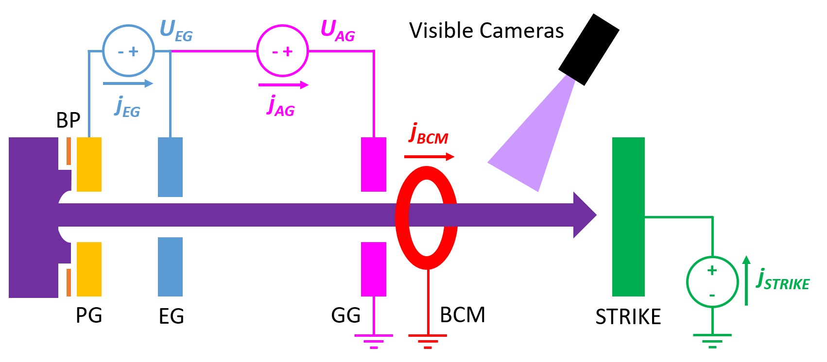
In SPIDER negative ions are extracted from the source by the extraction potential UEG applied between the Plasma Grid (PG), which encloses the source, and the Extraction Grid (EG). The negative ions are then accelerated by the acceleration potential UAG applied between the EG and the Grounded Grid (GG). UEG + UAG are applied such that the source is at negative voltage, up to -108 kV (U-12 kV + UAG = -96kV). Electrons are co-extracted from the source and are deflected onto the EG by embedded co-extracted electron suppression magnets (CESMs). To reduce the electron temperature in the extraction region a transverse filter field is generated by a vertical current through the PG IPG. The PG and a dedicated bias plate (BP) are biased positively with respect to the source to reduce the co-extracted electron current. The extraction and acceleration power supplies, named ISEG PS and AGPS, and the potentials applied to the three electrostatic grids are shown in figure 1. The ISEG and AGPS drain currents jEG and jAG provide estimations of the extracted ion current jex (jAG) and the co-extracted electron current (jEG-jAG).
The beam optics is determined by the beam perveance, defined by (2.1), and the electrostatic lens created by the extraction and acceleration potentials, with the strength of the lens given by UAG/UEG.
| (2.1) |
At perveance match and with an optimum ratio UAG/UEG the beam should be transmitted through the accelerator with a low divergence. Any large deviations in perveance or UAG/UEG can result in an increasing beam divergence and direct interception on the grids.
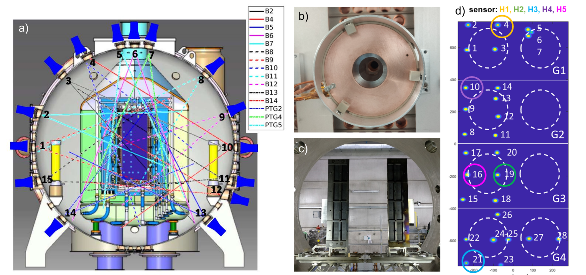
With the PG mask reducing the number of open apertures it is possible to resolve the current and optics of individual beamlets. SPIDER has three diagnostics that can measure the same beamlets; BCMs, visible camera tomography and the STRIKE calorimeter (the relative positions of the diagnostics are given in figure 1). The BCMs are five sensors mounted downstream of the GG (shown in figure 2b) that measure the accelerated current of five individual beamlets (coloured circles in figure 2d). Downstream of the GG 15 cameras are positioned around the vacuum vessel to collect the visible light emitted from the beam interaction with the background gas (camera Lines of Sight shown in figure 2a). Using tomographic reconstruction the intensity (proportional to the current) and width of all the individual beamlets can be obtained. The STRIKE calorimeter, separated into two halves vertically, can be positioned to intercept the whole SPIDER beam or either the left or right halves (figure 2c), with the non-intercepted beam continuing on to the SPIDER beam dump. For the recent campaigns the left half of STRIKE (looking downstream from the source) intercepted 23 of the 28 available beamlets. The beamlet footprints are resolved by IR calorimetry on the CFC tiles; from this the beamlet current, width and position is determined. In addition, each tile is biased positively to collect the secondary electrons emitted due to the beam impact on the tiles. This provides an electrical measurement of the negative ion current intercepted by STRIKE (jSTRIKE in figure 1). Of the five remaining beamlets three (5,6,7 in figure 2d) are measured by the AES, but the AES is not included in this comparison as they are different beamlets to the BCM and STRIKE. BES has also been excluded from this comparison.
3 Beam current comparison
During 2021 cesium was evaporated into the SPIDER source for the first time, from three Cs ovens [15] placed vertically between horizontal driver pairs on the source back wall. The campaign was carried out in multiple phases; an exploration of the caesiation parameters at low (phase 1) and higher RF power (phase 2), beam optics studies (phase 3), HV testing at higher power (phase 4) and deuterium operation (phase 5) [16].
With the change from volume dominant to surface dominant H- production the extracted ion current increased five-fold and the electron-to-ion ratio decreased to <1 within 110 plasma pulses. The average beam current measured by the AGPS, BCM and STRIKE show a clear increase with the introduction of Cs (figure 3), as well as a significant difference between jAG and the accelerated current measured by the BCM and STRIKE. At 50 kW/driver jAG reaches 180 A/m2, with the BCM and STRIKE lower at around 140-150 A/m2. Due to a decrease in vacuum quality in phase 4 the currents do not return to their highest values at 50 kW/driver.

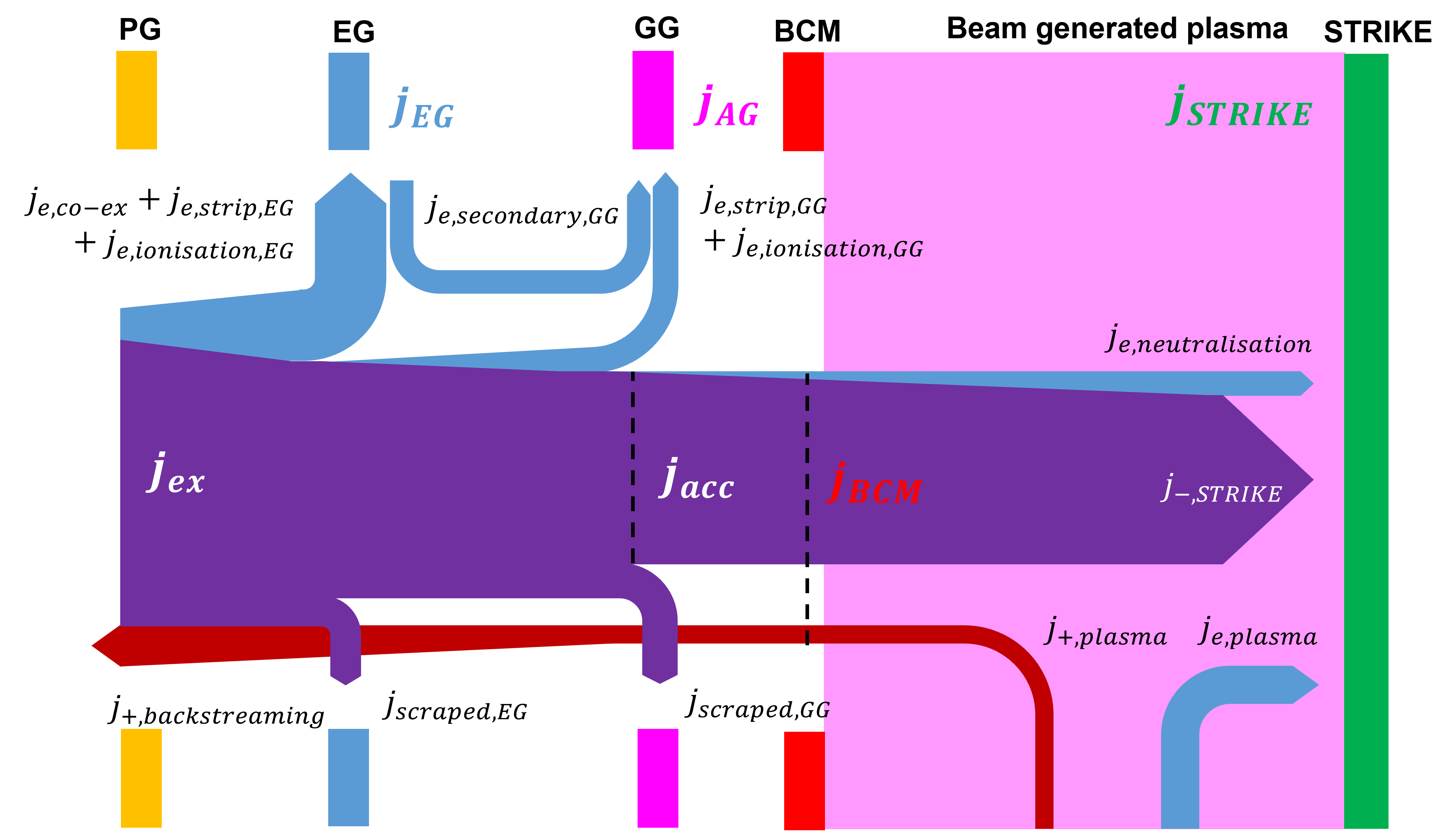
The differences between the three measurements can be explained by the relative locations of the diagnostics and the secondary charges produced in the accelerator due to the background gas (volume processes) or beam scraping (surface processes) that contribute to the measurements (figure 4). At the PG the beam current is composed of extracted H- jex and co-extracted electrons je,co-ex. Stripping and scraping of the beam results in an accelerated current jacc at the GG given by (3.1).
| (3.1) |
The stripping, scraping and ionisation, with the distribution of charges onto the different grids, result in jEG and jAG being subtly different from jex, je,co-ex and jacc. jEG (3.2) is the sum of all the contributions in the accelerator, including electrons and backstreaming positive ions due to ionisation of the background gas. jAG (3.3) is the accelerated current plus some contribution from the stripping, ionisation and scraping (through direct interception on the GG and secondary electrons from the EG) in the accelerator, denoted here by the GG subscript.
| (3.2) |
| (3.3) |
The BCM and STRIKE both measure closer to jacc. The BCM measures jacc almost directly (3.4), with a small additional contribution from backstreaming beam plasma positive ions. STRIKE collects the incident H- and electrons born from in-vessel neutralisation (je,neut, which are assumed to go in the beam direction and intercept STRIKE’s large surface area; these two contributions should equal jacc. Positively biased to recollect electrons emitted from its surface due to H- impact, STRIKE also collects the electrons from the beam generated plasma, which results in an over estimation of the accelerated current (3.5). This is seen in the slightly higher average current measured by STRIKE compared to the BCM. Both diagnostics are significantly lower than jAG. The following subsections attempt to characterise these differences.
| (3.4) |
| (3.5) |
3.1 Volume processes
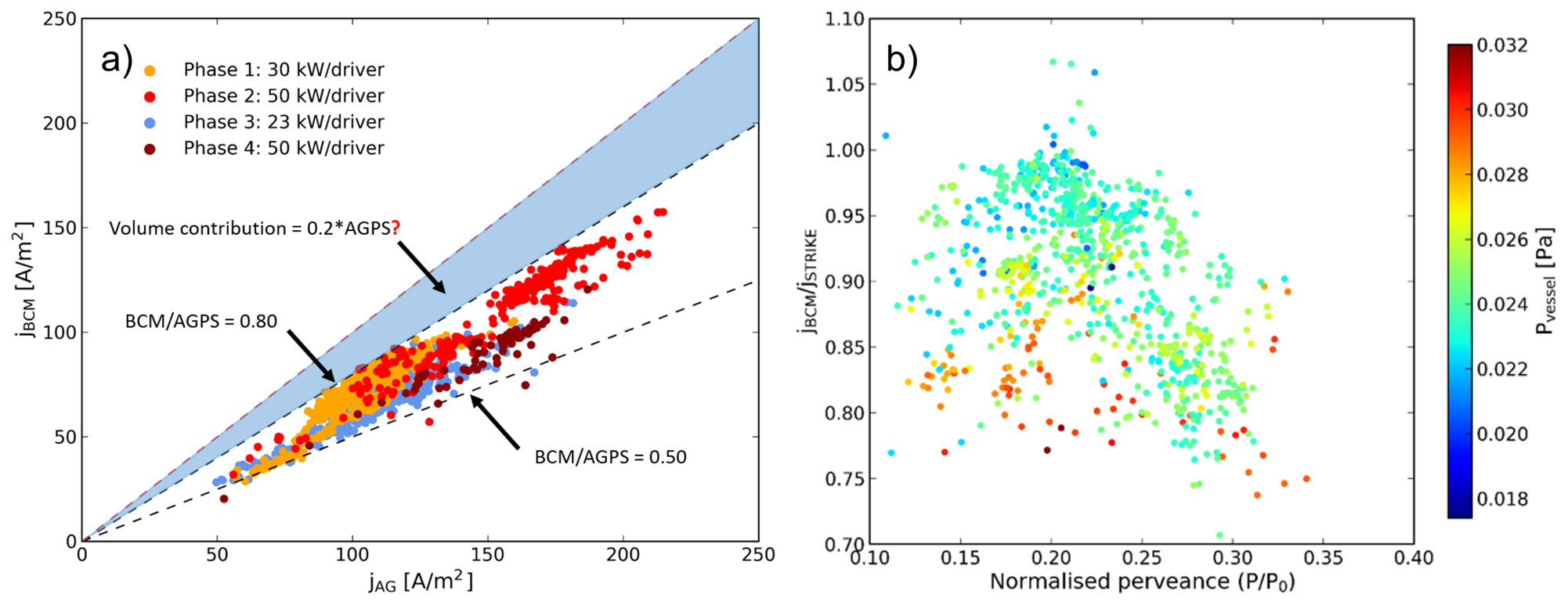
First comparing the BCM and AGPS measurements (figure 5a) there is a minimum 20% difference between the two. This is attributed to the volume contributions to jAG, namely the stripping and ionisation in the accelerator. No clear dependence of the current ratio on the source or vessel pressure is seen; most of the campaign was performed with a source filling pressure pfill around 0.35 Pa. Estimations of the stripping losses with the PG mask are around 7% of the extracted current [17], with BES analysis giving similar numbers [18]. Considering that ionisation will also contribute to the current, although to a smaller degree, 20% is a high but not unrealistic estimation of the volume processes, although it would require all of the additional charges to be collected by the AGPS and not shared with the ISEG PS. The remaining difference in BCM/AGPS we will characterise in the subsequent sections.
The ratio STRIKE/AGPS (not shown) is 5-10% higher than BCM/AGPS, attributed to the electrons collected from the beam plasma in the source. The BCM/STRIKE ratio shows a far smaller variation, as both are measuring currents close to jacc. There is some dependence on vessel pressure as expected (figure 5b); the main difference is the beam plasma, which is generated from the background gas in the vessel. The perveance is calculated using jAG, as it is the closest to jex. From OPERA simulations optimum perveance is around 0.26P0 for jex = 355 A/m2 and UEG = 9.4 kV [19]. P0 is the perveance limit for a planar diode, given by (3.6) where dPGEG is 6 mm.
| (3.6) |
3.2 Initial ceasiation
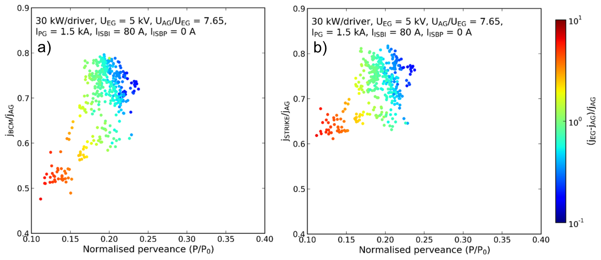
Taking the pulses from the initial ceasiation at 30 kW/driver (phase 1, orange points in figure 5a) the current ratio BCM/AGPS and STRIKE/AGPS both increase as the perveance increases towards 0.26P0 (figure 6). The co-extracted electron to ion ratio decreases (using the difference between jEG and jAG for the co-extracted electrons) as the ratio improves. This improvement can be taken as an increase in the beam transmission as the optics improve with ceasiation.
3.3 Overperveance
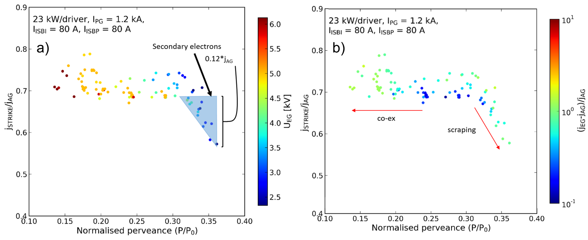
On the other hand, overperveance, where UEG is too low for the available current, results in a decrease in the current ratio. This can be seen in pulses taken from phase 3, where dedicated studies of the beam source parameters and optics were performed once the source was well caesiated. In figure 7, during extraction voltage scans the ratio of STRIKE/AGPS current drops considerably past 0.3P0. This is due to scraping of the over-perveance beam onto the EG, resulting in secondary electrons that are collected by the AGPS but not by STRIKE (or the BCM). These secondary electrons make up to approximately 12% of jAG at >0.35P0. The difference between jEG and jAG increases as the perveance decreases, due to an increase in the co-extracted electron current. Over perveance, the difference also increases due to scraping on the EG.
4 Individual beamlets
The individual beamlets are compared using the BCM, STRIKE IR calorimetry and tomography, with the latter two providing information on the beamlet divergence as well as the current. The beamlet current for the five BCM beamlets follow the same trend with extraction voltage and for all three diagnostics (figure 8a). The current of each beamlet increases with UEG, eventually reaching a saturation point where all the available H- is extracted. The saturation voltage is not reached in this case, but Shepherd et al. [13] has shown that this occurs at UEG > 6 kV for this RF power. The inhomogeneity in the beamlet current can be estimated as the standard deviation of the beamlet currents divided by the mean of the beamlet currents (4).
| (4.1) |
For each diagnostic the current inhomogeneity of the five BCM beamlets has a minimum at the same UEG (figure 8b). It is worth noting that the increase in inhomogeneity either side of the optimum UEG is due to the different behaviour of the bottom beamlet H3. The bottom of the SPIDER source has a lower plasma density due to vertical drifts induced by the filter field, and a lower H- availability. A study of the beam plasma uniformity, and the resulting current uniformity, has been carried out by Serianni et al [20].
One difference between the three diagnostics is the intensity of the top beamlet H1, as measured by tomography, compared to the current measured by STRIKE and the BCM. For the tomography H1 is consistently lower than the other beamlets, resulting in a higher overall inhomogeneity. This is even more apparent when considering all of the available beamlets for the diagnostics (red and blue lines in figure 8b). For STRIKE with more beamlets there is less variation in the inhomogeneity with UEG, but the overall trend does not change. For the cameras the inhomogeneity is higher and no longer has a trough, due to a larger variation between beamlet intensities at all UEG compared to STRIKE. The camera calibrations may explain the wider range of intensities, in particular the lower intensity of beamlet H1. For the tomography the central beamlet of the vertical group of three has been excluded (beamlet 6 in figure 2) as it has a much lower intensity than the other three. This may be due to the difficulty in isolating the beamlet from it’s neighbours for the tomographic reconstruction. Its inclusion results in an increase in the blue inhomogeneity line of over 5%.
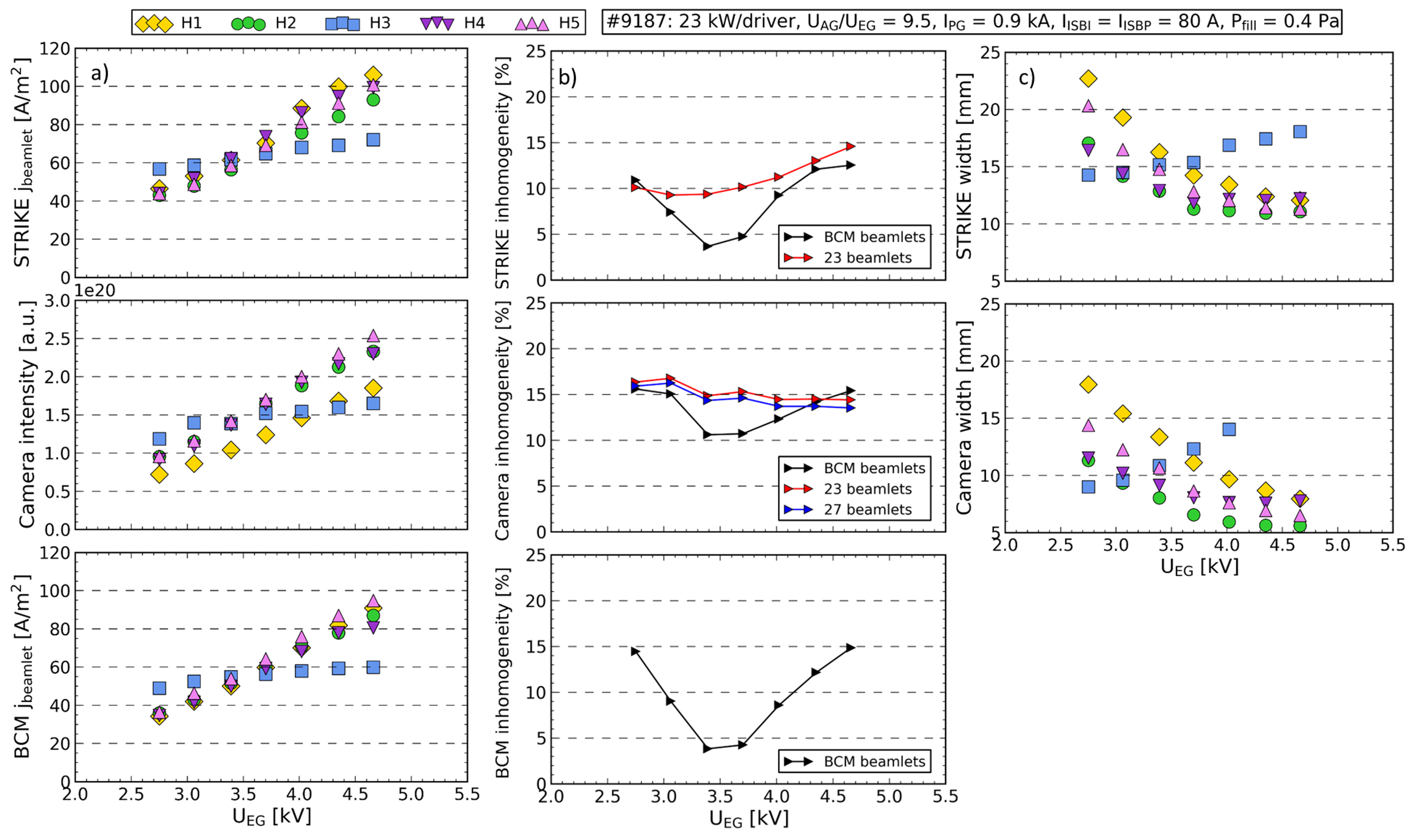
The beamlet width, calculated from STRIKE and tomography, has a minimum where the current deviates from the Child Langmuir law (figure 8c), i.e. where the current saturates due to H- availability (generally >5 kV for IPG = 0.9 kA). The only exception is H3, which for both diagnostics has a minimum width at much lower UEG. Combined with the higher current at low UEG the implication is that the other beamlets may be scraping on the EG, which reduces the measured accelerated current.
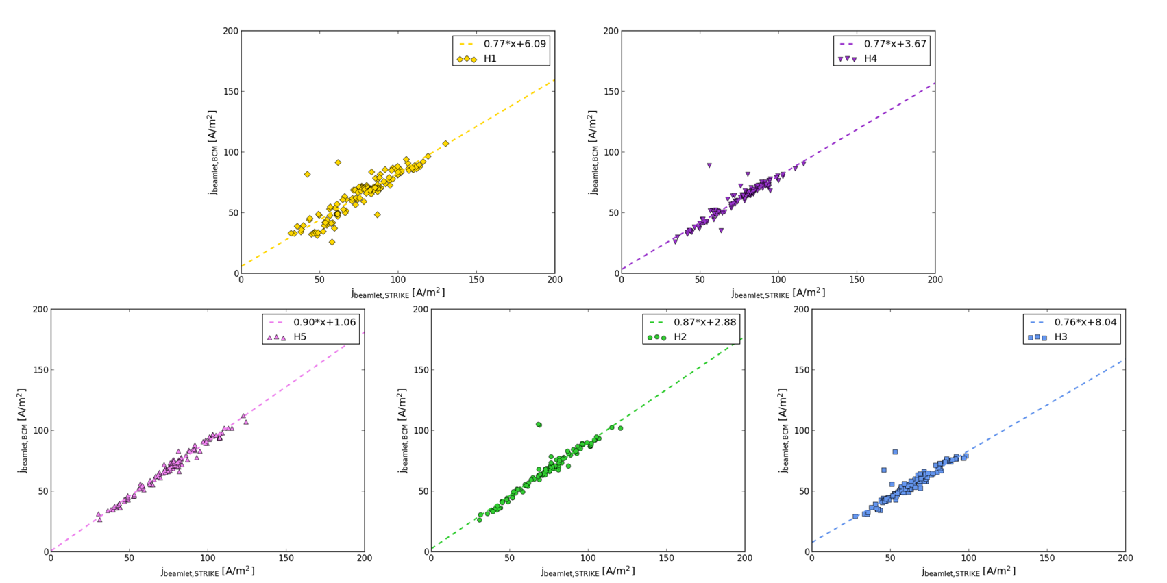
Taking all the pulses from the 23 kW/driver optics studies the individual beamlets compare consistently between the BCM and STRIKE IR current measurements (figure 9), with a BCM/STRIKE ratio ranging from 0.76 to 0.9. The variation between the beamlets is likely due to the varying emmissivity of the STRIKE CFC tiles, both from tile to tile and across each tile. However, within the source parameter variations in phase 3 the BCM and STRIKE IR current ratios are unchanged.
5 Conclusion
With the reduction of the number of open apertures on SPIDER it has been possible to measure the current of some of the apertures directly using the BCM. The current measurements compare well with existing diagnostics that can resolve the same individual beamlets. Comparing the average BCM current to the STRIKE electrical current, both provide a more accurate measurement of the accelerated current than the AGPS drain current. The latter is affected by secondary charges, with additional work needed to quantify these components.
Plans to increase the number of beamlets measured by the BCM for the next SPIDER campaign with the PG mask will improve the accuracy of the current comparison. A study into the design of beamlet group current sensors, for when the PG mask is removed, is also underway.
Acknowledgments
This work has been carried out within the framework of the ITER-RFX Neutral Beam Testing Facility (NBTF) Agreement and has received funding from the ITER Organization. The views and opinions expressed herein do not necessarily reflect those of the ITER Organization.
This work has been carried out within the framework of the EUROfusion Consortium, funded by the European Union via the Euratom Research and Training Programme (Grant Agreement No 101052200 — EUROfusion). Views and opinions expressed are however those of the author(s) only and do not necessarily reflect those of the European Union or the European Commission. Neither the European Union nor the European Commission can be held responsible for them.
This work was supported in part by the Swiss National Science Foundation.
References
- [1] R.S. Hemsworth, D. Boilson, P. Blatchford, M.D. Palma, G. Chitarin, H.P.L. de Esch et al., Overview of the design of the ITER heating neutral beam injectors, New Journal of Physics 19 (2017) 025005.
- [2] M. Bacal, M. Sasao and M. Wada, Negative ion sources, Journal of Applied Physics 129 (2021) 221101.
- [3] V. Toigo, R. Piovan, S.D. Bello, E. Gaio, A. Luchetta, R. Pasqualotto et al., The PRIMA Test Facility: SPIDER and MITICA test-beds for ITER neutral beam injectors, New Journal of Physics 19 (2017) 085004.
- [4] G. Serianni, V. Toigo, M. Bigi, M. Boldrin, G. Chitarin, S. Dal Bello et al., SPIDER in the roadmap of the ITER neutral beams, Fusion Engineering and Design 146 (2019) 2539.
- [5] R. Pasqualotto, G. Serianni, P. Sonato, M. Agostini, M. Brombin, G. Croci et al., Diagnostics of the iter neutral beam test facility, The Review of scientific instruments 83 (2012) 02B103.
- [6] R. Pasqualotto, M. Agostini, M. Barbisan, M. Brombin, R. Cavazzana, G. Croci et al., A suite of diagnostics to validate and optimize the prototype ITER neutral beam injector, Journal of Instrumentation 12 (2017) C10009.
- [7] A. Pimazzoni, M. Brombin, G. Canocchi, R.S. Delogu, D. Fasolo, L. Franchin et al., Assessment of the SPIDER beam features by diagnostic calorimetry and thermography, Review of Scientific Instruments 91 (2020) 033301.
- [8] M. Ugoletti, M. Agostini, M. Brombin, F. Molon, R. Pasqualotto and G. Serianni, First results of SPIDER beam characterization through the visible tomography, Fusion Engineering and Design 169 (2021) 112667.
- [9] M. Barbisan, B. Zaniol, R. Pasqualotto, G. Serianni and M. Ugoletti, First results from beam emission spectroscopy in SPIDER negative ion source, Plasma Physics and Controlled Fusion 63 (2021) 125009.
- [10] M. Pavei, S. Dal Bello, G. Gambetta, A. Maistrello, D. Marcuzzi, A. Pimazzoni et al., SPIDER plasma grid masking for reducing gas conductance and pressure in the vacuum vessel, Fusion Engineering and Design 161 (2020) 112036.
- [11] C. Poggi, E. Sartori, M. Tollin, M. Brombin, M. Zaupa, E. Fagotti et al., Design and development of an Allison type emittance scanner for the SPIDER ion source, Review of Scientific Instruments 91 (2020) 013328.
- [12] A. Shepherd, B. Pouradier-Duteil, T. Patton, A. Pimazzoni, A.R. Garola, E. Sartori et al., Initial Results From the SPIDER Beamlet Current Diagnostic, IEEE Transactions on Plasma Science (2022) 1.
- [13] A. Shepherd, T. Patton, B. Pouradier Duteil, A. Pimazzoni, A. Rigoni Garola and E. Sartori, Beam homogeneity of caesium seeded spider using a direct beamlet current measurement, Fusion Engineering and Design 192 (2023) 113599.
- [14] B. Pouradier Duteil, A. Shepherd, T. Patton, A. Rigoni Garola and R. Casagrande, First characterization of the spider beam ac component with the beamlet current monitor, Fusion Engineering and Design 190 (2023) 113529.
- [15] A. Rizzolo, M. Pavei and N. Pomaro, Caesium oven design and R&D for the SPIDER beam source, Fusion Engineering and Design 88 (2013) 1007.
- [16] E. Sartori, M. Agostini, M. Barbisan, M. Bigi, M. Boldrin, M. Brombin et al., First operations with caesium of the negative ion source SPIDER, Nuclear Fusion 62 (2022) 086022.
- [17] E. Sartori, V. Candeloro, M. Fadone, A. Pimazzoni and G. Serianni, Influence of plasma grid-masking on the results of early spider operation, Fusion Engineering and Design 194 (2023) 113730.
- [18] R. Agnello, M. Barbisan, R. Pasqualotto, A. Pimazzoni, C. Poggi, E. Sartori et al., Measurement of stripping losses in the negative ion source spider, Fusion Engineering and Design 186 (2023) 113350.
- [19] P. Agostinetti, V. Antoni, M. Cavenago, G. Chitarin, N. Marconato, D. Marcuzzi et al., Physics and engineering design of the accelerator and electron dump for SPIDER, Nuclear Fusion 51 (2011) 063004.
- [20] G. Serianni, E. Sartori, R. Agnello, P. Agostinetti, M. Agostini, M. Barbisan et al., Spatially resolved diagnostics for optimization of large ion beam sources, Review of Scientific Instruments 93 (2022) 081101.