3D Model-based Zero-Shot Pose Estimation Pipeline
Abstract
In this paper, we present a CAD model-based zero-shot pose estimation pipeline called ZeroPose. Existing pose estimation methods remain to require expensive training when applied to an unseen object, which greatly hinders their scalability in the practical application of industry. In contrast, the proposed method enables the accurate estimation of pose parameters for previously unseen objects without the need for training. Specifically, we design a two-step pipeline consisting of CAD model-based zero-shot instance segmentation and a zero-shot pose estimator. For the first step, there is a simple but effective way to leverage CAD models and visual foundation models SAM and Imagebind to segment the interest unseen object at the instance level. For the second step, we based on the intensive geometric information in the CAD model of the rigid object to propose a lightweight hierarchical geometric structure matching mechanism achieving zero-shot pose estimation. Extensive experimental results on the seven core datasets on the BOP challenge show that the proposed zero-shot instance segmentation methods achieve comparable performance with supervised MaskRCNN and the zero-shot pose estimation results outperform the SOTA pose estimators with better efficiency.
1 Introduction
Pose estimation plays a crucial role in various robotic and augmented reality applications. Existing deep-learning methods [pvn3d, ffb6d, uni6dv2, chen2023geo6d] achieve remarkable performance for seen objects after absorbing a large amount of training data for each target object. However, when there is a novel (unseen) object introduced, it requires significant time and effort to synthesize or annotate data and re-train the model from scratch. This greatly restricts the universality and scalability of models, and the high time and training costs further hinder the practical application of pose estimation with novel objects. Hence, there is a pressing need for a pose estimation method that enables training once and generalizing to any unseen object during inference, addressing these challenges effectively.
To improve the generalization of pose estimation methods, some works [lin2022icra:centerpose, wang2019normalized, chen2020category, li2022polarmesh, manhardt2020cps++, manuelli2019kpam, wen2021catgrasp] leverage a category-level pose estimation pipeline, which can reduce the requirement of training for different instances in one category. However, generalization capabilities are not guaranteed when object instances that belong to categories are not included in the training data. Since the unlimited and unpredicted categories in the open-world environment of augmented reality (AR) applications, category-level methods become unaffordable. Some methods [sun2022cvpr:onepose, he2022oneposeplusplus, he2022cvpr:fs6d] propose a CAD-model-free based novel object pose estimation pipeline. It estimated the pose based on one or a few user-annotated images, and estimate the relative pose transformation by feature descriptor matching of 2D images. For AR applications, the goal of pose estimation is to set the “virtual anchors" of AR effects [sun2022cvpr:onepose]. Annotating the poses of target objects at the beginning frames of the video is an efficient and user-friendly way for their systems. While for robotic manipulation in the industry, the target object is typically artificially manufactured, whose CAD model is typically known and easily obtainable. In the robotic grasping task, the CAD model is critical for calculating and planning grab points. Hence, the CAD-model-based pose estimation methods are suitable and urgent for robotic manipulation. Furthermore, since the CAD model does not require any samples from the test scene, the CAD-model-based pose estimation pipeline can be defined as a special type zero-shot setting with CAD model prompt [park2020latentfusion, okorn2021zephyr]. Given a CAD model as input, OSOP [shugurov2022cvpr:osop] based on 2D images rendering from CAD model to segment the object and estimate the pose by 2D-2D correspondence. However, this pipeline is limited to segmenting only a single instance of each object and cannot handle multi-instance scenes like the bin-picking task. Since the missing instance-level object localization method, the recent zero-shot object poses estimation method Megapose [labbe2022megapose] assumes the instance-level localization provided as input, and estimate pose by online pose hypotheses view rendering and compared with the scene instance. Ignoring the detection of unseen objects affects the application in practice in a zero-shot manner. Additionally, the efficiency of the model is constrained by the abundance of hypotheses.
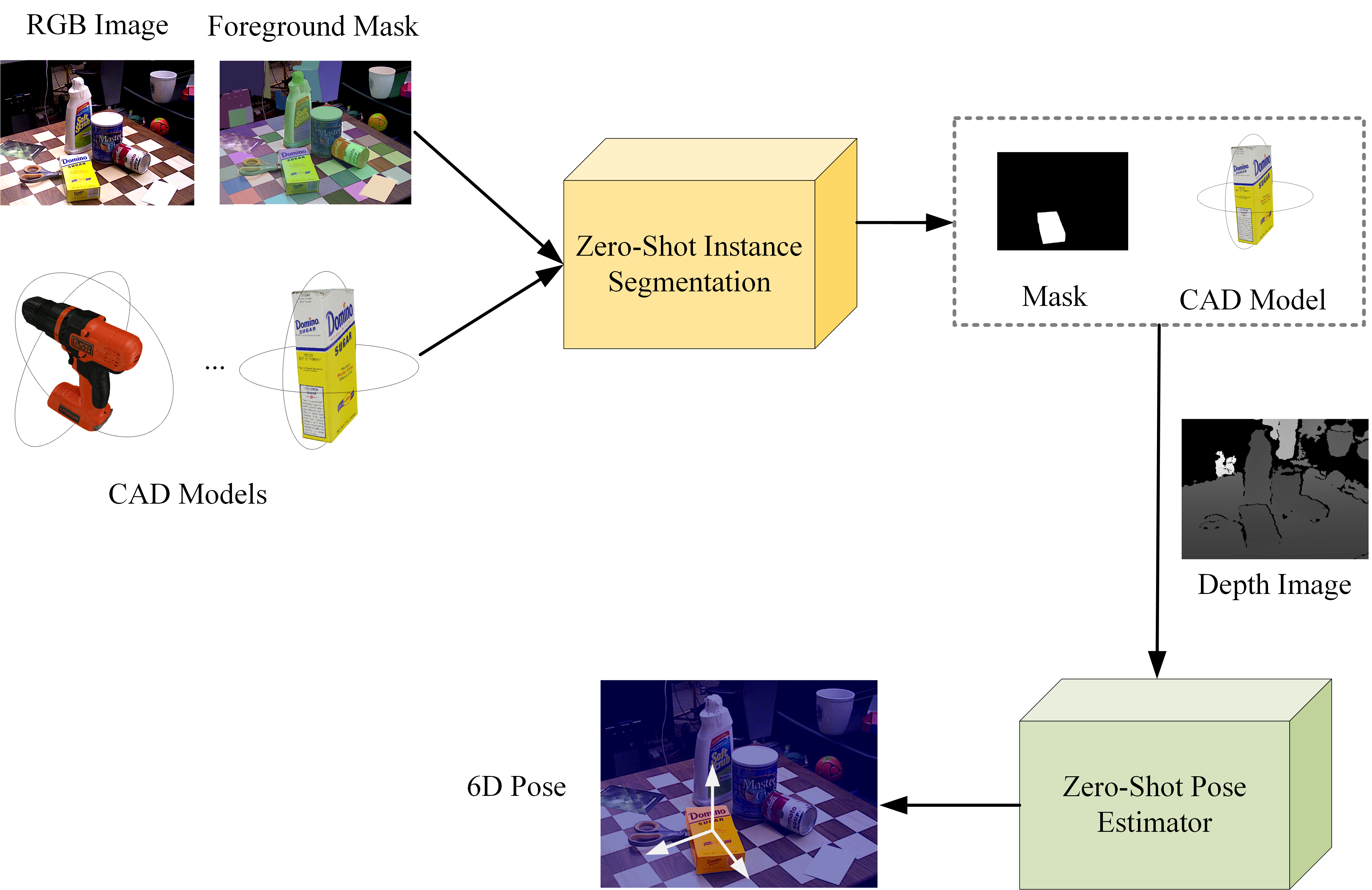
To improve the scalability and generalization of pose estimation in the industry, we proposed a CAD-model-based zero-shot estimation method. As shown in Fig 1, it follows the common two steps pipeline [uni6d, uni6dv2, labbe2022megapose], where instance location is followed by pose estimation, and the proposed method extends each step into the CAD-model-based zero-shot setting without the need for training when unseen object coming. In the first step, we introduce a simple yet effective method to leverage different visual foundation models to achieve instance segmentation. Specifically, there are three stages, first, extract visual descriptors of the CAD model by rendering in a few views synthetic images and leverage the visual foundation model ImageBind [imagebind] to extract features as visual descriptors of this object. Second, we use SAM [sam] to predict foreground instances as candidates. Third, based on visual descriptors of objects, we filter out interested instance regions and assign the object id as their label achieving instance segmentation. In the 6D pose parameter estimating step, we propose a novel zero-shot pose estimator through geometric structure matching. Unlike existing render-based methods, it offers the advantage of direct 3D structure matching between scene point clouds and CAD models, eliminating the need for rendering images and improving efficiency. During the test time, the proposed hierarchical geometric feature matching module first locates the visible region in the CAD model and based on the geometric feature calculates the 3D-3D correspondences to estimate the pose.
In summary, our paper makes the following key contributions:
-
•
Introduction of a fully zero-shot pose estimation pipeline.
-
•
Proposal of a simple yet effective zero-shot instance segmentation method.
-
•
Development of a lightweight zero-shot pose estimator based on hierarchical geometric feature matching.
-
•
Extensive experiments show that our proposed segmentation method in a zero-shot setting achieves comparable accuracy with the supervised instance segmentation method MaskRCNN and the pose estimation results outperform the SOTA pose estimators with better efficiency.
2 Related Work
In this section, we will begin by providing an overview of the existing research on the zero-shot instance segmentation problem. Subsequently, we will delve into the extensive research conducted on the unseen object 6D pose estimation.
2.1 Zero-Shot Instance Segmentation
Instance segmentation involves predicting a mask for each object and assigning corresponding class labels. It is typically performed as a prerequisite task for 6D pose estimation. However, previous research [xie2021unseen, shugurov2022cvpr:osop, xiang2021learning, ornek2023supergb, sam, zou2023segment] has primarily concentrated on zero-shot semantic segmentation and zero-shot category-agnostic instance segmentation. Some methods [xie2021unseen, ornek2023supergb] leverage the RGB and depth image for unseen object instance segmentation in a semantic category-agnostic manner. OSOP [shugurov2022cvpr:osop] is the closest work to ours, which is based on the reference image feature as clues to segment the related object. However, it semantic segmentation pipeline requires there only one instance for each object and is not available in the cluster scene where multiple instances for each object. Inspired by the development of prompt-based universal interfaces for large language models, both SAM [sam] and SEEM [zou2023segment] propose a model that is purposefully designed and trained to be promotable. This promotable model exhibits the ability to effectively transfer its knowledge and skills in a zero-shot manner to novel image distributions and tasks.
However, the aforementioned methods are primarily designed to predict foreground instances or instances associated with specific textual prompts that are not suitable for the pose estimation field. The main reason is the limitations in missing the capabilities of distinguishing the class label (related CAD model) of the candidate instances. In the case of foreground instance segmentation, the method fails to attribute the foreground instance to a specific object without human interaction. In the case of text-prompt instances segmentation, challenges arise in accurately describing complex properties of objects, such as their shape and materials, using natural language. This task requires domain experts with relevant knowledge, especially in specialized fields like industrial manufacturing or robotics applications. Additionally, foundation models may struggle to comprehend these professional descriptions, resulting in difficulties or errors. In summary, the field lacks a dedicated zero-shot instance segmentation method that effectively leverages 3D models
2.2 Unseen Object 6D Pose Estimation
Category-level pose estimation is proposed to alleviate the expensive training cost in recent methods [lin2022icra:centerpose, wang2019normalized, chen2020category, li2022polarmesh, manhardt2020cps++, manuelli2019kpam, wen2021catgrasp]. When encountering unseen objects, the pipeline only needs to be trained once for each category, instead of training for each individual object. However, this solution remains inapplicable when the category of the object does not exist in the known training categories or there is a significant difference in shape and appearance.
CAD-model-free pose estimation methods [sun2022cvpr:onepose, he2022oneposeplusplus, he2022cvpr:fs6d] leverage one-shot or few-shot pose-annotated images of the object as a reference to estimate the object pose in query images as the “virtual anchors" of AR effects. Since this pipeline is designed for AR, the target object is arbitrary, the CAD model is unknown and only perform in a video. Therefore, annotating the object poses in a few scene images of the video is an adorable and effective way to perform pose estimation in AR applications. However, in the industrial manufacturing field, objects are typically artificially manufactured, and their CAD models are usually given and critical for robotics to calculate grab points and accessibility detection.
CAD-model-based pose estimation is introduced in recent methods [shugurov2022cvpr:osop, okorn2021zephyr, labbe2022megapose]. Since the CAD model is known and predefined for robotic grasping and not requires any annotated samples from the real scene, these methods can be seen as zero-shot learning. These methods widely adopt a rendering-based method that renders many pose hypothesis views as templates to train the network to distinguish the best pose from image similarity. While this solution is intuitive, it faces a particular efficiency issue. Due to the unpredictable object location and its correlation with appearance, a large number of pose hypothesis samples must be rendered to approximate the object in the scene improving the computational costs. Besides, it can not fully perform on the zero-shot setting and it requires an instance-level localization input provided by the user. Both of them restrict their availability in practical applications. The proposed ZeroPose introduces a lightweight zero-shot pose estimation method by hierarchical 3D-3D geometric feature matching without the time consumption poses hypothesized rendering shows great improvement for efficiency.
3 Method
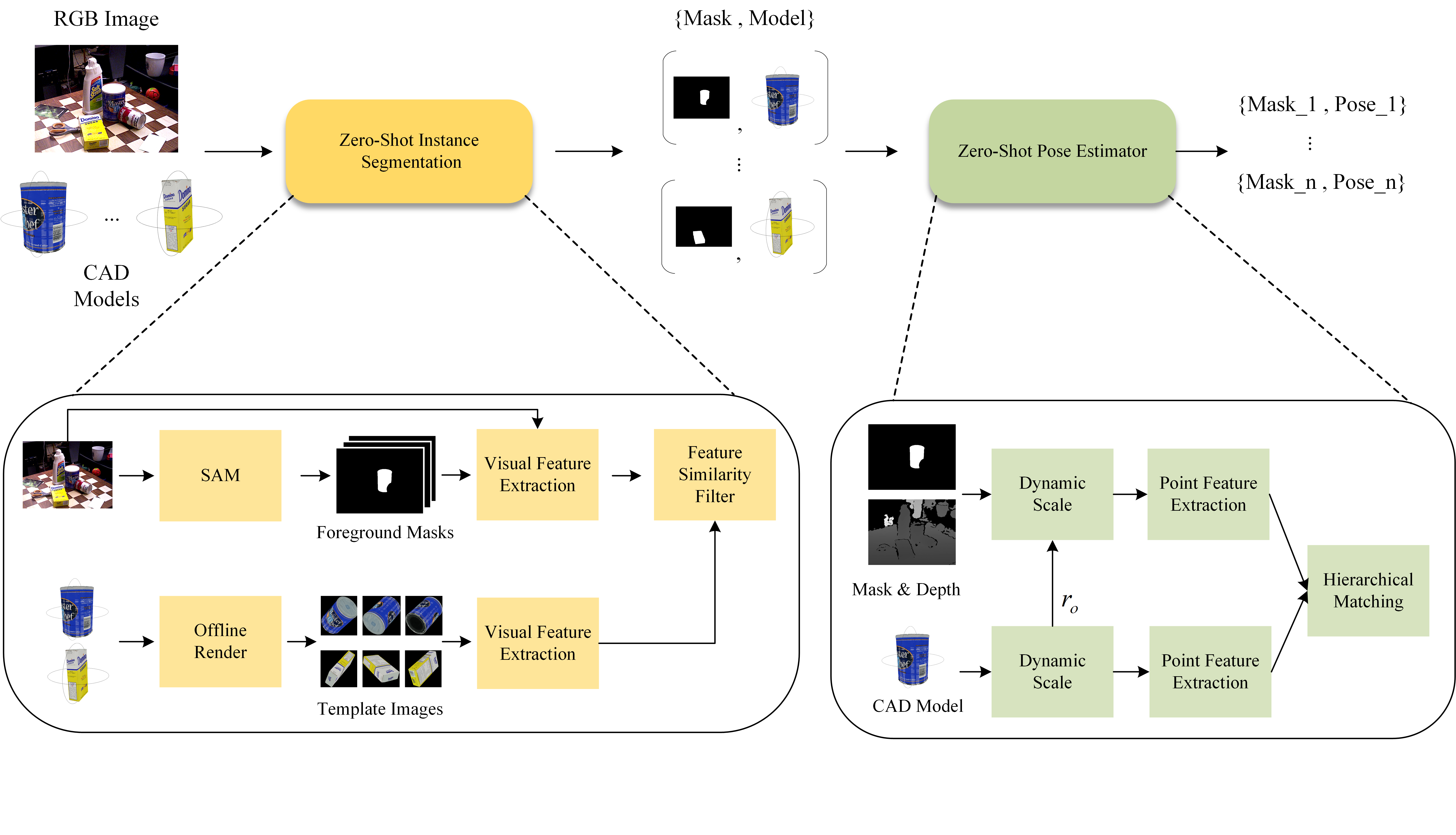
Fig 2 illustrates our detailed implementation of the proposed zero-shot pose estimation pipeline which consists of two steps. We will provide a thorough explanation of the two steps in the following subsections, respectively.
3.1 CAD model-based Zero-Shot Instance Segmentation
As indicated by the yellow box in Fig 2, the target of the instance segmentation step is to search all potential instances related to the provided CAD models. To leverage the CAD model clues, we first render the CAD model from different camera views achieving a set of 2D template images. A visual foundation model ImageBind [imagebind] is utilized to extract visual features from the template images as the visual clues of the CAD model, which can be presented in with shape , where is the number of all candidate CAD models, is the number rendered template images and is the feature dimension for visual foundation model.
For the scene image, we adopt a category-agnostic segmentation method SAM [sam] taking a uniform point set as a prompt to generate all foreground masks without labels. Then, similar to the template images, we crop all foreground instances and extract their visual features through the same visual foundation model as the template images. It presents as with shape where is the number of foreground masks. To assign the foreground instances with a label id corresponding with their objects, a feature similarity filter module calculates the cosine feature similarity between scene instances and template objects to filter out the potential instance and label it with the object model ID with the maximum feature similarity. There is the calculation formula,
| (1) |
where is the cosine distances matrix with shape and any element in it is the score for feature similarity. The instance mask is labeled with the CAD model ID of the highest score rendered image and the instance mask and its label consist of the zero-shot instance segmentation.
3.2 CAD model-based Zero-Shot Pose Estimator
As indicated by the green box in Fig 2, the target of the pose estimator is to estimate rigid transformation of the CAD model from the target object’s object coordinate systems to the camera coordinate system, where is a 3D rotation and is a 3D translation.
Since the CAD model and the depth image of the scene are easy to acquire in the industry application, matching them by 3D-3D point correspondence is an intuitive way. However, in practice, it is challenging to establish point correspondences between them due to two main reasons: (i) diversity in object scale, and (ii) low inlier rate (overlap ratio for two point clouds). There are significant differences in object scale from 2 cm to 47cm in the BOP datasets. The wide range of object size distribution makes it difficult for the network to choose a suitable fixed receptive field scale for matching features to perform 3D-3D matching. For instance, a fixed receptive field scale, such as 0.2 cm, may be too large for tiny objects that lack precise estimation, and potentially too small for large objects that lack distinctiveness. The reason for the low inlier rate is from the visibility. For the CAD model, a set of point clouds is uniformly sampled from the surface of the mesh. For the scene points, the mask is applied to index the object region from the depth image and convert it into a scene point cloud . The scene point cloud refers to a subset of the CAD model point cloud that contains only the visible region that can be captured. Different viewpoints of the camera will correspond to a specific visible region in the object CAD model. Revisiting the percentage of the visible region in the image within the CAD model, we find that most samples are less than 15%, which leads to a low inlier rate. There are only a few points reliable for matching, and the rest large amount points in the CAD model are outliers disturbing the matching. Besides, the scene point cloud is captured from the depth sensor and cropped from the detection mask, which unavoidably includes some surrounding noisy points. These make it difficult for zero-shot learning methods to be achieved through efficient 3D-3D matching.
We proposed a novel 3D-3D zero-shot pose estimation method to solve these challenges. It consists of two modules of a dynamic scale module and a hierarchical matching module.
Dynamic scale module is proposed to solve the object scale problem. Given scene point clouds and the related CAD model point clouds, we first normalize both point clouds into zero-meaned and adopt the radius of the circumscribed sphere of the CAD model to scale the coordinates of physical dimensions into unit relative to . The relative unit to their can well solve the problem of invalid matching due to scale differences. Besides, we take the radius as a prior constraint to cluster the scene point through a Mean-Shift algorithm to filter the noisy points. These two operations build a normalized and clean input feeding into the following subsequent hierarchical matching modules.
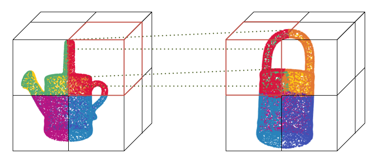
Hierarchical matching module is proposed to extract hierarchical point cloud features for 3D-3D matching. As shown in Fig 3, the high-level feature with a larger receptive field (the red boxes) is utilized to choose the best viewpoint from predefined viewpoints of the CAD model according to the visible region. After that, a low-level feature is applied to find the point-to-point correspondence (green dotted lines) between the predicted visible region of the CAD model and the scene point cloud. The hierarchical design confines the matching scope within the visible area and alleviates the mismatching between visible and invisible regions. Based on the correspondence, we minimize the point cloud distance in Eq (2) to calculate a target through Singular Value Decomposition (SVD).
| (2) |
where and are matched corresponding points.
In order to obtain representative high-level and low-level features, we take the GeoTransformer[qin2023geotransformer] as our point extraction backbone model, and re-train it on the large-scale CAD model dataset GSO [downs2022google] to learn viewpoint matching and local geometric structure matching. The backbone model produces features at multiple levels. The high-level features have a larger receptive field and are discriminative, while the low-level features have a smaller receptive field and can provide precise location information. For the training of high-level features, we adopt the overlap-aware circle loss [qin2023geotransformer], denoted as , to train the model to locate the high overlap region. It selects the visible region of the CAD model and its corresponding scene point cloud area as positive samples. The others that have an overlap of less than a threshold are viewed as negative samples. For the low-level features, the small receptive field can be seen as a point-level feature adopted for Eq (2) to calculate the 3D point correspondences. During the training phase, we adopt the ground truth pose to match the point pairs by the distance within a matching radius, and negative log-likelihood loss to train the network to find the matched pairs. At the inference, we use the prediction correspondences as and based on the coordinate of points estimate the pose transformation. High-level and low-level features can be simultaneously trained in a network architecture with an equal weight based on their respective loss functions. The final loss is
| (3) |
For detailed training methods and specifics, please refer to the implementation details section.
4 Experiments
max width= Method Zero-Shot Real LM-O T-LESS TUD-L IC-BIN ITODD HB YCB-V Mean 1 Mask RCNN[maskrcnn] 37.5 51.7 30.6 31.6 12.2 47.1 42.9 36.2 2 Mask RCNN[maskrcnn] 37.5† 54.4 48.9 31.6† 12.2† 47.1† 52.0 40.5 3 ZebraPoseSAT[su2022zebrapose] 50.6 62.9 51.4 37.9 36.1 64.6 62.2 52.2 4 ZebraPoseSAT[su2022zebrapose] 50.6† 70.9 70.7 37.9† 36.1† 64.6† 74.0 57.8 5 Text-based 11.8 0.1* 0.2* 18.0 6.8 0.0* 34.9 14.4 6 Ours 34.4 32.7 41.4 25.1 22.4 47.8 51.9 36.5
4.1 Benchmark
Datasets For the training dataset, we take the GSO [suresh2023midastouch] to train our pose estimation module, which contains 1000 3D objects under household scenes and 1 million synthetic images provided by Megapose [labbe2022megapose]. For the test datasets, we evaluated our method on the seven core datasets of the BOP challenge [hodavn2020bop], including LineMod Occlusion (LMO), T-LESS, TUD-L, IC-BIN, YCB-Video (YCB-V) ITODD, and HomebrewedDB (HB). The first 5 datasets are named BOP 5 usually conduct the ablation study on it and all of them are BOP 7. These datasets are enriched with diverse factors of variation, including scale, texture, symmetry, and household or industrial scenes, which accurately represent the different types of objects typically encountered in daily and robotic scenarios.
Instance Segmentation Metrics Following the COCO metric and the BOP Challenge, we evaluate the performance of instance segmentation by Mean Average Precision (mAP) which is the mean of AP at different Intersection over Union (IoU=.50:.05:.95) values.
Pose Estimation Metrics Following [hodavn2020bop], in order to measure the accuracy of an estimated pose in relation to the ground-truth pose of an object model , we utilize the mean Average Recall of three pose-error functions, calculated by and more information about evaluation metrics for the threshold to calculate the AR can be obtained from the BOP competition.
4.2 Evaluation of Zero-Shot Instance Segmentation
We conduct the experiments on seven BOP Challenge datasets. Since there are no other related methods following the CAD-model-based Zero-Shot Instance Segmentation setting, we select two supervised methods with training by the test objects and implement a text-based zero-shot instance segmentation method for comparison. The Mask RCNN method [maskrcnn] is from the CosyPose [cosypose], which is trained on the real or synthetic training datasets for each test object. The ZebraPoseSAT [su2022zebrapose] is the current SOTA method for the instance segmentation task, which leverages a two-stage setting that detection for coarse locating and pose estimation network for refinement. For the text-based zero-shot instance segmentation, we hold the same pipeline with our method and adopt the text embedding of the object name as the template feature, instead of the template image features to evaluate and compare the performance. For the T-LESS, TUD-L, and HB datasets, there are only object IDs without class names provided. As depicted in Tab 1, our CAD-model-based zero-shot instance segmentation method shows obvious performance improvements compared with the text-based method from 14.4 % to 36.5 % and outperforms the Mask RCNN method with training on the test objects.
max width=
| Instance Localization | Pose Estimation | BOP Datasets | |||||||||||||
|---|---|---|---|---|---|---|---|---|---|---|---|---|---|---|---|
| Method | \makecell[b]Zero-shot | \makecell[b]Inst. level | \makecell[b]Zero-shot | \makecell[b]Refinement | lm-o | t-less | tud-l | ic-bin | itodd | hb | ycb-v | Mean | |||
| 1 | CosyPose | 63.3 | 64.0 | 68.5 | 58.3 | 21.6 | 65.6 | 57.4 | 57.0 | ||||||
| 2 | DPODv2 | 63.0 | 43.5 | 79.1 | 45.0 | 18.6 | 71.2 | 53.2 | 53.4 | ||||||
| 3 | SurfEmb | 75.8 | 82.8 | 85.4 | 65.6 | 49.8 | 86.7 | 80.6 | 75.2 | ||||||
| 4 | Megapose | – | 18.7 | 19.7 | 20.5 | 15.3 | 8.00 | 18.6 | 13.9 | 16.2 | |||||
| 5 | Ours | – | 26.1 | 24.3 | 61.1 | 24.7 | 26.4 | 38.2 | 29.5 | 32.6 | |||||
| 6 | Megapose | 58.3 | 54.3 | 71.2 | 37.1 | 40.4 | 75.7 | 63.3 | 57.2 | ||||||
| 7 | Ours | 56.2 | 53.3 | 87.2 | 41.8 | 43.6 | 68.2 | 58.4 | 58.4 | ||||||
| 8 | OSOP | 48.2 | - | - | - | - | 60.5 | 57.2 | - | ||||||
| 9 | Ours | – | 26.0 | 17.8 | 41.2 | 17.7 | 38.0 | 43.9 | 25.7 | 25.7 | |||||
| 10 | Ours | 49.1 | 34.0 | 74.5 | 39.0 | 42.9 | 61.0 | 57.7 | 51.2 | ||||||
4.3 Evaluation of Zero-Shot Pose Estimation
To evaluate our pose estimation performance, we compared the supervised methods without zero-shot setting and the latest zero-shot pose estimation methods. The zero-shot task can not achieve any object prior which is quite challenging and has performance limitations compared with the supervised method. Since current pose refinement methods can generalize to unseen objects, the most challenge is the pose initialization. Compared with Megapose [labbe2022megapose], our method achieves 15.6% performance gain as the rows 4,5 shown in Tab 2. After adopting the same refiner, our method surpasses Megapose 1.2%. Besides, the megapose [labbe2022megapose] has a limitation in that it is required a supervised Mask RCNN to locate the candidate object but our method is able to estimate the pose in and fully zero-shot manner with a comparable performance of 51.2%. Compared with OSOP [shugurov2022cvpr:osop], although its object localization module is zero-shot, the semantic segmentation introduces the restriction of one instance for one object limiting its applicability to scenarios where multiple instances for one object. The proposed ZeroPose not only surpasses OSOP on their provided three datasets but also shows high applicability on the cluster scene which is critical for industry application such as Bin-Picking.
max width=
| Method | Runtime per object (s) |
|---|---|
| Megapose[labbe2022megapose] | 2.5 |
| Ours | 0.3 |
4.4 Time Efficiency
Compared to current zero-shot 6D pose estimation methods, the proposed pose estimation method based on point cloud feature 3D-3D matching eliminates the time-consuming online image rendering operation. As presented in Table 3, our method achieves an impressive pose estimation time of 0.2 seconds per object, which is ten times faster than the current state-of-the-art zero-shot method[labbe2022megapose].
4.5 Ablation Study
4.5.1 Comparison of the template images generation methods.
To investigate the effect of template image generation methods, we conduct an experiment on Tab 4. There are two types of render strategies provided. The first strategy St.1 is a fast employment version that renders the image by Pyrender program with some predefined uniform sampling pose [nguyen2022template]. It can prepare the rendered images for each CAD model in seconds, suitable for applications such as AR with high requirements for onboarding time. The second strategy St.2 is an improved version for industry applications with high precision requirements. It increases the number of candidate poses to catch as different as possible appearances of objects and leverages the BlenderProc to synthetic more realistic images. Besides, we use K-means as a cluster to remove the similar appearance samples. While ensuring sample diversity, the computational overhead of the execution has been reduced. The experiment results show that both two strategies achieve adorable performance and the offline strategy achieves 3% additional advance. To show the potential of zero-shot pose estimation in the industry, we choose St.2 with 128 for the following pose estimation step.
max width= Number Memory (MB) AP (%) \multirow 3* St.1 42 0.16 47.5 162 0.64 48.1 642 2.51 48.9 \multirow 2* St.2 32 0.13 51.2 128 0.50 51.9
4.5.2 Effect of dynamic scale module and hierarchical matching module
To validate the effectiveness of the proposed dynamic scale module and hierarchical matching module, we conduct an ablation study on these modules. As demonstrated in Tab 5, this hierarchical matching method is able to improve the matching accuracy and shows 9% improvement by removing the most outlier regions. The dynamic scale module holds a stable scale of receptive fields for matched features to advance the performance into 50.2 for the BOP 5 datasets.
max width= Dynamic scale Hierarchical matching AR(%) – – 17.1 – 26.1 50.2
max width=
| Visual Model | AP (%) |
|---|---|
| SLIP[mu2022slip] | 36.6 |
| ImageBind[imagebind] | 51.9 |
4.5.3 Comparison of Different Visual Foundation Models
The visual feature extraction foundation models depend on the accuracy and robustness of the label selection in the zero-shot instance segmentation step. There is an experiment for two different foundation modules SLIP [mu2022slip] (an advanced version of CLIP [clip]) and ImageBind [imagebind] (a recent multi-modal pertaining method). The results in Tab 6 show that a larger and stronger foundation model increases the average precision and recall significantly.
4.6 Implementation Details
The zero-shot pose estimation pipeline is trained on the SLURM cluster with 8 NVIDIA V100 and inferring on the PC with NVIDIA RTX 3090.
Foreground Instance Segmentation It adopts the recent SOTA interactive segmentation method SAM [sam], uniformly setting 32 points per side of images as the prompt of Decoder to generate the mask of foreground instances and filtering out the tiny regions less than 200 pixels. Besides, the Intersection over Union (IoU) threshold in the NMS mechanism is set to 0.6 for removing the duplicating region in predicting masks.
Visual Feature Extraction The large-scaled visual foundation model ImageBind [imagebind] takes the resized image with shape (224, 224, 3) as input to extract the scene images and template images visual features in (N, C) where N is the number of images and C is the feature dimension for 1024 in this experiment. In the text prompt version, we adopt the text embedding of the name of the object provided by their methods as the template feature.
Hierarchical Matching Mechanism We take the GeoTransormer [qin2023geotransformer] as the backbone to extract hierarchical point cloud features and match the potentially visible regions based on the feature from level 4 and points matching based on the feature from level 2. For the input feature, we supply the RGB and normal information as the input feature of point clouds. For the receptive field, the high level is , and the low level is . It trains on the 10% data amount of the GSO dataset with 80 epochs. At the inference, there are following the same setting of hyperparameters for all the test bop datasets.
5 Conclusion
In this paper, we propose a fully zero-shot pose estimation pipeline based on the CAD model. Our pipeline consists of a CAD-model-based zero-shot instance segmentation module to segment the candidate object at the instance level from the scene image and a lightweight zero-shot pose estimator is introduced to estimate the pose transformation between the object coordinate system to the camera coordinate system based on the 3D to 3D hierarchical point cloud structure matching mechanism. In a zero-shot setting, our proposed segmentation method achieves comparable accuracy to the supervised instance segmentation method, MaskRCNN. Additionally, our pose estimation results outperform state-of-the-art (SOTA) zero-shot pose estimators with improved efficiency.
There is a limitation in that CAD models are not used as prompts in the zero-shot instance segmentation module because SAM [sam] only supports text, point, box, and mask prompts. We will try to explore a multi-modality model to support CAD model prompts in future work. The proposed pipeline operates fully in a zero-shot setting and demonstrates faster performance compared to previous approaches. This pipeline holds promise for inspiring innovative solutions in various fields, including industrial manufacturing, robotics, and beyond.
Appendix A Comparison with only zero-shot pose estimation
Since the current zero-shot pose estimation method, Megapose [labbe2022megapose], operates within the supervised instance segmentation setting, it is necessary to establish a fair comparison with our proposed zero-shot pose estimator. To achieve this, we integrate the zero-shot instance segmentation results with the segmentation results obtained through supervised training using MaskRCNN [maskrcnn], which aligns with Megapose’s methodology.
Compared to Megapose, our proposed zero-shot pose estimator exhibits a significant performance gain in terms of the mean average recall (AR) score across the seven BOP core datasets, increasing from 17.7% to 25.0%. Our method generally outperforms Megapose 8.6% in terms of the mean average recall (AR) score. For LM-O and T-LESS datasets, the performance is comparable because there is a limitation from the low signal-to-noise ratio of the scene’s point clouds. The number of points from the scene object region is too small and the percentage of noise from the depth sensor or segmentation result will be increased. Consequently, the accuracy of the scene’s geometric structure is compromised, making it challenging to estimate the correct pose accurately.
| Method | ZSIS | ZSPE | LM-O | T-LESS | TUD-L | IC-BIN | ITODD | HB | YCB-V | Mean |
|---|---|---|---|---|---|---|---|---|---|---|
| MegaPose[labbe2022megapose] | ✗ | ✓ | 18.7 | 19.7 | 20.5 | 15.3 | 8.00 | 18.6 | 13.9 | 16.4 |
| Ours | ✗ | ✓ | 15.2 | 19.2 | 30.6 | 25.0 | 24.5 | 31.6 | 28.8 | 25.0 |
| Ours | ✓ | ✓ | 14.2 | 6.3 | 24.9 | 18.7 | 13.6 | 23.6 | 22.9 | 17.7 |
Appendix B Pseudo Code
We present the PyTorch-style pseudocode of the proposed zero-shot pose estimation Algorithm 1.