Phase-field modelling of failure in ceramics with multiscale porosity
Abstract
Many stiff biological materials exhibiting outstanding compressive strength/weight ratio are characterized by high porosity, spanning different size-scales, typical examples being bone and wood. A successful bio-mimicking of these materials is provided by a recently-obtained apatite, directly produced through a biomorphic transformation of natural wood and thus inheriting its highly hierarchical structure. This unique apatite (but also wood and bone) is characterized by two major distinct populations of differently-sized cylindrical voids, a porosity shown in the present paper to influence failure, both in terms of damage growth and fracture nucleation and propagation. This statement follows from failure analysis, developed through in-silico generation of artificial samples (reproducing the two-scale porosity of the material) and subsequent finite element modelling of damage, implemented with phase-field treatment for fracture growth. It is found that small voids promote damage nucleation and enhance bridging of macro-pores by micro-crack formation, while macro-pores influence the overall material response and drive the propagation of large fractures. Our results explain the important role of multiscale porosity characterizing stiff biological materials and lead to a new design paradigm, by introducing an in-silico tool to implement bio-mimicking in new artificial materials with brittle behaviour, such as carbide or ceramic foams.
keywords:
porous materials; multiscale porosity; bio-mimetic materials; phase field approach to fracture; finite element method.1 Introduction
Materials characterised by a high-density distribution of voids are diffused in nature (for instance bone, wood, rock –sandstone, tuff, pumice–, coal) and as man-made materials (for instance concrete, cellular ceramic, and carbide foam). Wood and bone evidence populations of cylindrical pores with nearly circular cross-sections, ranging in diameter through multiple size scales, a feature affecting many of their physical [1, 2, 3] and mechanical [4, 5, 6] properties. Implementing size-scale variation in the porosity of artificial materials is a bio-mimicking challenge, particularly for bone substitutes and scaffolds [7, 8, 9, 10]. A successful answer to this challenge was provided [11] through the synthesis of a new material, a 3-D porous apatite (called ‘Biomorphic Apatite’, BA in the following) obtained via a bio-morphic transformation of natural wood into ceramics, Fig. 1.
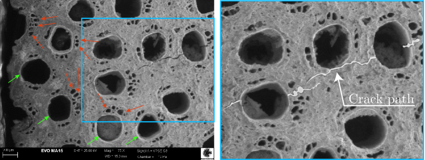
BA replicates the multiscale hierarchical structure of wood, with a double-sized porosity (Fig. 1), sharing similarities with bone and thus becoming ideal for bio-mechanical applications, where outstanding strength and fracture energy absorption are crucially important [1, 12]. Here, a correct failure analysis may lead to the design of surgical interventions and prediction of rehabilitation times so that the development of a numerical tool for this analysis is the object of the present paper. A class of materials (including those addressed here, plus glass, ceramic, rock and concrete) are brittle, so that fracture nucleates primarily under tensile stresses. Under overall compression, crack generation is complicated by the presence of voids, which concentrate tensile stress near their boundary and stimulate fracture growth parallel to the loading direction [13, 14, 15], see Fig. 1. Fracture patterns are typically tortuous and difficult to follow or model analytically [16], so that numerical techniques play a decisive role. These can be classified as: (i.) augmented versions of the finite-element method [17] (such as cohesive-zone methods, CZM, or extended finite-element methods, XFEM, the former requiring an initial knowledge of the crack pattern and the latter an ad hoc constitutive relation at the crack tip); (ii.) diffusive damage models [18, 19, 20, 21] (relying on a regularized crack topology); (iii.) the phase-field approach, overcoming the difficulties encountered in the other techniques by allowing damage to grow within a thin portion of the material. The latter technique has been developed as an energy minimization, via -convergence regularization of free discontinuities to model cracks [22, 23, 24, 25, 26, 27, 28, 29] and was recently proven to be particularly suitable for the description of complex fracture patterns in PMMA samples with notches and holes [30] and therefore is adopted here.
The porosity typical of biomorphic apatite is primarily double sized, so that macro-scale pores can be differentiated from meso-scale pores, Fig. 1 (micropores, also present, are neglected as they were found not to influence fracture) and is shown to correspond to two peaks of a probability density function. This function allows the set-up of a numerical tool for the generation of in-silico porous samples, to be used for subsequent fracture simulation using the phase-field technique.
The simulations show that the porosity is always connected to a reduction of overall stiffness and strength of the material. However, the meso-scale porosity produces: (i.) a smearing of damage through zones that would remain intact in the absence of this scale of pores; (ii.) a shielding of regions of the material from cracks; and (iii.) a promotion of fracture growth in other zones.
Our results show that, not only the value of ‘total porosity’ is relevant to the mechanical modelling of porous-brittle solids, rather the amount of fractions of porosity with different characteristic size plays a strong role, a result with implications in the simulation of fracture in biological porous materials, such as bone or wood, and in porous ceramics for bone repair or for filters used in industrial applications.
2 Results
2.1 Theory
In a purely isothermal formulation of a brittle-damaging material, where the damage only occurs for tensile strains, the Helmholtz free energy per unit volume can be represented as
| (1) |
a function of a damage parameter , where represents a residual stiffness. Note that the lower extremum of the range of variation for corresponds to an intact material, while to a fully damaged one. Equation (1) embodies an additive split of the elastic energy into tensile, ‘’, and compressive, ‘’, strains
| (2) |
where and () are the unit eigenvectors and corresponding eigenvalues of the strain, respectively, and denotes the Macaulay bracket operator, defined for every scalar as .
The Helmholtz free energy, Eq.(1), defines a diffuse and isotropic damage model, where damage only occurs in tension, so that the stress tensor
| (3) |
becomes the sum of tensile and compressive components, both related to the strains through the isotropic elasticity tensor as
| (4) |
Following the variational approach to brittle fracture, propagation and branching of a crack in a damaging solid can be found as the result of the minimization of the energy functional [28, 31]
| (5) |
where is the displacement, is the fracture energy and is the (unknown and evolving) fracture path inside the body .
A direct use of the functional (5) involves the solution of a free boundary value problem, which can be approximated by following the regularised framework introduced with the phase field approach [23, 28]. The approximation regards the topology of the crack, which is smeared out onto the whole body, allowing to rewrite the potential energy of the system as a volume integral
| (6) |
where is the crack density functional, depending on the spatial gradient of the internal state variable , now called ‘phase field variable’.
The surface , not explicitly present in the functional (6), can be recovered as the result of an energy minimization procedure. In particular, introducing the so-called ‘AT2 model’ [28, 25], the functional , is represented by the following convex function
| (7) |
where is a regularisation characteristic length, related to the smeared crack width. For a sufficiently small , the minimization of functional (6), implemented with the nonlocal crack density function (7), ‘spontaneously’ leads to a solution where the damage is strongly localized near a surface , representing a crack. Formally, it can be demonstrated that, for vanishing regularisation parameter (), the formulation outlined in Eq.(6) tends to Eq.(5) in the sense of the so-called ‘-convergence’ [27].
Finally, the weak form of the variational problem, and the consequent finite-element discretization, can be found in [30].
3 Virtual testing
3.1 Two scale porosity and mesh generation
A brittle porous material is now considered, characterized by a two-scale cylindrical porosity. A two-dimensional formulation fits the specific transverse structure that biomorphic apatite (‘BA’ henceforth) inherits from rattan wood, which presents elongated grains and parallel channels, with approximately circular cross-section and two predominant sizes (Fig. 1).
The BA samples are characterized by three size-levels of porosity (defined as the ratio between the volume of voids and the total volume of the element in a representative volume element), namely, macroscopic (approximately 300 m in diameter), mesoscropic (up to 50 m in diameter), and microscopic (1 m of diameter) [1]. Using an ad hoc developed Matlab code (based on image analysis functions ‘imread’ and ‘imfindcircles’, available in the complementary material), the porosity of BA, as characterized from SEM photomicrographs, was shown to obey to the following probability distribution function (PDF)
| (8) |
which exhibits the bi-modal shape, clearly visible in Fig. 2 (black dashed curve).
The peak on the right of the curve occurs at high values of void radius and is representative of macro-porosity , while the peak on the left is representative of meso-porosity , so that, neglecting the micro level, the total porosity is the sum of the two following major contributions .
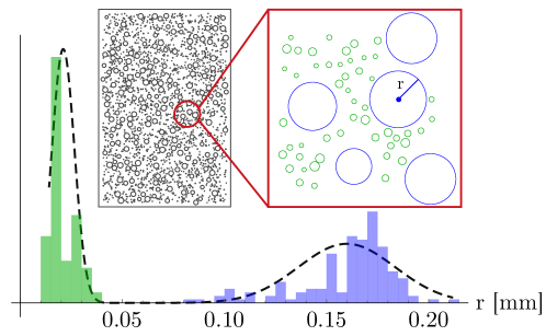
The obtained PDF was used for in-silico generation (through random placement of non-overlapping voids) of samples of porous materials (an example is shown in the inset of Fig. 2), needed for simulations (performed at the Laboratory for Numerical Modelling of Materials of the University of Trento, using a Workstation AMD Ryzen Threadripper PRO 5995WX, 512GB RAM, 2 GeForce RTX 3090 graphic cards, acquired with the ERC-AdG-2021-101052956-Beyond), via the previously outlined phase-field approach.
In order to investigate the influence of two size-scale porosity on crack patterns in ceramic materials subject to uniaxial compression, a preliminary calibration (reported in the supporting material) on single-porosity samples [generated by simply neglecting the right term in equation (8)] has been performed for both mechanical model and mesh size for subsequent finite element solution. Results of this analysis are shown in the supporting material.
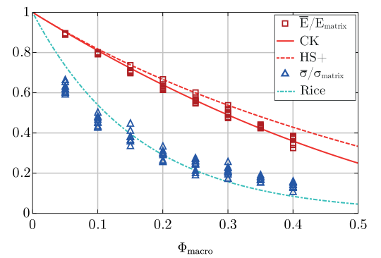
For a material characterized by a porosity , independently of the number of size-scales of porosity, the overall stiffness of an equivalent homogeneous material can theoretically be estimated in a number of ways. Following the Coble-Kingery model [32, 33], the effective Young’s modulus , defining a homogeneous elastic solid equivalent to the porous material, is
| (9) |
where is to be chosen, for spherical voids and Poisson’s ratio close to 0.2. The Hashin-Shtrikman upper bound [34] was also used, see supporting material.
The peak stress under increasing uniaxial stress (corresponding to failure in a force-controlled testing device), for a sample made of an equivalent homogeneous material, is assumed to follow the simple rule [35]
| (10) |
where is the peak (or failure) stress in the matrix material and a coefficient to be fitted with experimental measurements.
Equations (9) and (10) are used as reference in the simulations, in particular, once the Young’s modulus and failure stress of the matrix material are assigned for numerical calculations, the above equations are employed to obtain an expected ‘rough’ behaviour of porous samples.
Simulations of uniaxial compression tests have been performed for values of (single-scale) macro-porosity equal to 5%, 10%, 15%, 20%, 25%, 30%, 35%, 40% (see the supporting material). For each value of porosity, ten specimens with different distributions of pores have been considered and, accordingly, ten different overall stress/strain responses have been obtained [in terms of and L]. Results for three (of the ten) samples characterized by a macro porosity of 20% are shown in Fig. 3.
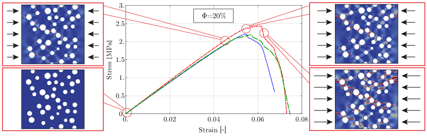
Here, in full agreement with experimental results, simulations show that the response of the specimens remains almost linear until a peak value of stress is reached, and it is followed by a softening branch, due to the coalescence of small cracks.
The shape of the softening branch and the value of the peak stress greatly depend on the geometrical distribution of voids, while the stiffness (the tangent line to the stress-strain curve) is only slightly influenced. Fig. 3 is enhanced with insets, showing crack growth at different test stages, developing parallel to the direction of applied loading. The last feature, agreeing with experiments, reveals that the model can effectively capture damage nucleation, fracture propagation and the final failure mechanism.
The mean value and standard deviation of overall stiffness (Young’s modulus ) and strength (peak stress ) are reported in Table 1, evaluated using simulations pertaining to the ten specimens tested for each porosity level. Predictions obtained with Eqs.(9) and (10) are included in parentheses and show a tight agreement with the numerical values.
| Mean() | 61.9 (63.2) | 55.2 (56.7) | 49.1 (50.6) | 43.5 (44.8) | 38.9 (39.4) | 34.4 (34.3) | 29.8 (29.6) | 25.2 (25.2) |
|---|---|---|---|---|---|---|---|---|
| Mean() | 4.53 (5.38) | 3.34 (3.99) | 2.76 (2.96) | 2.13 (2.19) | 1.76 (1.62) | 1.53 (1.20) | 1.25 (0.89) | 1.04 (0.66) |
| St. Dev() | 0.17 | 0.22 | 0.79 | 1.06 | 1.15 | 1.29 | 0.46 | 1.57 |
| St. Dev() | 0.17 | 0.17 | 0.23 | 0.18 | 0.21 | 0.18 | 0.08 | 0.12 |
It can be noted from the table that at an increase of macro-porosity, the effect of the void distribution on the overall strength tends to decrease, while the stiffness remains almost constant.
Fig. 4 summarizes results for specimens characterized by a single-scale porosity, by displaying values of peak stress and stiffness, as functions of the amount of porosity. Data compare well with predictions from Eq.(9), from the Hashin-Shtrikman upper bound, and Eq.(10).
3.2 Compression test on porous brittle solids: two-scale porosity
The phase-field approach to fracture mechanics is shown now to answer several questions that may arise when modeling or designing functional porous ceramics. In particular, at a fixed value of total porosity (7 values are explored, see supplementary material), simulations on in-silico created samples are used with different percentages of macro and meso voids, to explore effects related to second-scale porosity on: (i.) overall Young’s modulus, (ii.) failure stress, (iii.) crack growth, and (iv.) damage diffusion.
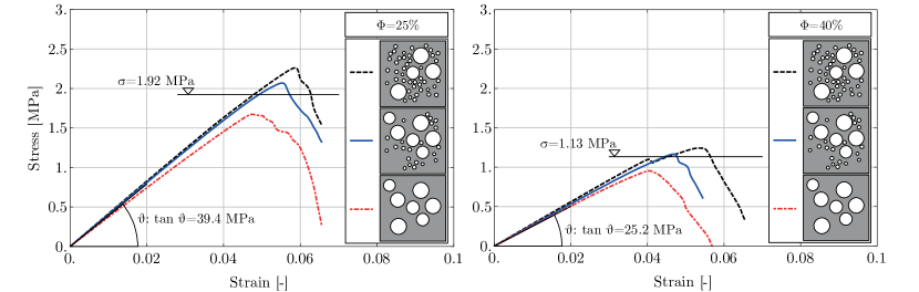
Overall stress/strain curves, analogous to those presented in Fig. 3, but now computed for double-scale porosity, are depicted in Fig. 5. Here, the total porosity (sum of the macro and meso values, ) is assumed to be equal to 25% (left) and 40% (right). Each curve represents the response of a sample in which the overall porosity is achieved by mixing different portions of macro-pores and meso-pores, where the former pores have a larger size than the latter, according to the PDF, Eq.(8). The peaks of the curves shown in Fig. 5 reveal that a superior mechanical response for specimens follows from an increase in the percentage of meso-pores. The left image of the same figure shows specimen with a total porosity of split in macro-porosity and meso-porosity as follow: the red dot-dashed curve is characterised by of macro-porosity, the blue one by macro-porosity and meso-porosity, and lastly, the black dashed one by macro-porosity and meso-porosity. The image on the right shows the effect is reproduced also for a total porosity of .
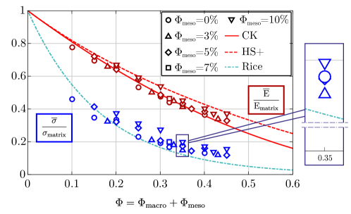
Overall properties, in terms of peak strength and elastic modulus, for different specimens are shown in Fig. 6, as functions of the total porosity, but for different values of meso (and thus also macro) porosity. According to [36], the figure reveals that for a fixed value of total porosity, samples display improved mechanical properties at low macro porosity (triangles are located clearly above the trend lines). Therefore, macro porosity is more detrimental to stiffness and strength than meso-porosity. However, our computations show that this is not a strict rule, as evidenced in the inset of Fig. 6, showing that a sample at 0.35 total-porosity with 0.03 meso-porosity is less stiff and resistant than the sample with null meso-porosity. This feature is not isolated and occurs also at and is related to the particular geometrical distribution of voids and prompts the idea that the design of the spatial void distribution (possible via phase field) could improve material performances.
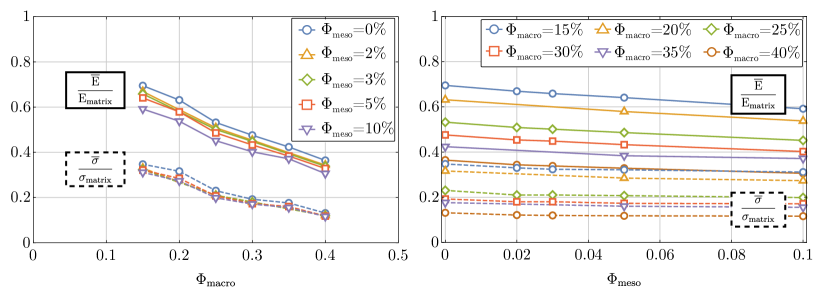
Both scales of porosity are found to concur in producing a non-linear effect on the overall properties of the porous material. In particular, an interaction is observed between the two scales of porosity (the sum between the two and is constant and equal to ). This emerges from the plots of the dimensionless peak strength and Young’s modulus reported in Fig. 7 as resulting from simulated stress-strain curves, functions of macro and meso-porosity and . Simple linear regression of the normalized overall properties obtained from our two-scale porosity analyses (depicted in Fig. 7) leads to the following approximations
| (11) | |||||
| (12) |
where R2 is the coefficient of determination.
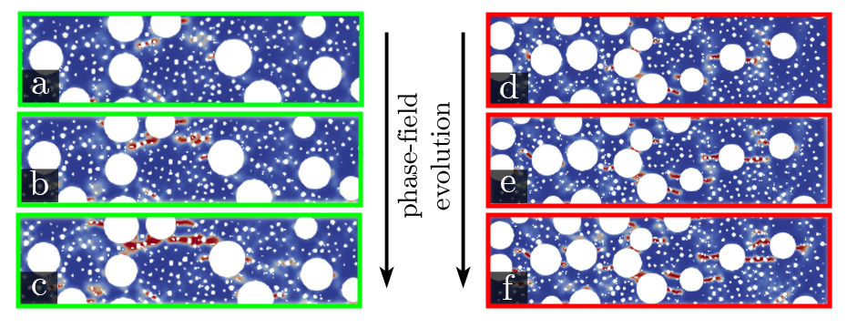
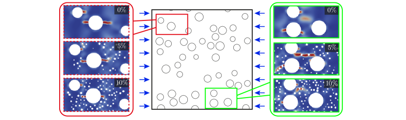
Crack patterns are found to be strongly influenced by meso-porosity at fixed values of macro-porosity, as shown in Fig. 8,
where simulations of crack patterns in two portions of a sample (one framed green and the other red) are
shown at different stages of loading, during a compression test for
and
.
Here, simulations reveal the existence of
two mechanisms of failure affecting specimens
characterized by double porosity: (i.)
in the portion of the sample framed red,
cracks nucleate at the edge of macro-pores, while meso-pores promote the development of a crack network, while (ii.) in the portion framed green, cracks nucleate near meso-pores and develop by joining macro-pores.
Crack paths in two-scale porous specimens
The presence of meso-porosity does not only affect the overall mechanical behaviour of a specimen in terms of stiffness and strength, but also its failure. The meso-porosity enhances damage diffusion and promotes new fracture paths, different from those observed in the absence of meso pores, as visible in Fig. 9, on the left, for . Here crack patterns are analyzed in a region of a sample compressed at a fixed value of overall strain, but with different amounts of meso-porosity, equal to 0 %, 5 %, 10 %. In the region reported on the right, meso-porosity, which produces large volumes of solid where damage grows, is shown to shield from damage.
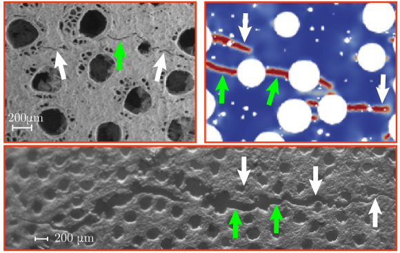
A direct comparison between a phase-field simulation of fracture growth in a porous material and two micrographs obtained during a compression test on BA, performed at the MUSAM-Lab (financed with the ERC StG CA2PVM, Grant Agreement 306622, and the ERC PoC PHYSIC, Grant Agreement No. 737447, at IMT School, Lucca), is presented in Fig. 10 (upper part on the left and lower part). The tests were executed by placing prismatic samples in direct contact with two steel platens (lateral size and thickness ) and compressed (using the tensile/compressive stage DEBEN 5000S inside the scanning electron microscope Zeiss EVO MA15) by imposing displacements. The test was continued until complete failure of the samples. Two mechanisms of crack propagation can be observed in Fig. 10: cracks either nucleate in the proximity of large pores and develop horizontally (highlighted in the figure with green arrows), or they nucleate near meso pores, thus producing a fracture network, where macro and meso pores are connected (highlighted in the figure with white arrows). The results of the simulation (upper part on the right) are not coincident with the fracture experiments because the sample used for simulation is randomly generated and therefore not identical to those analyzed experimentally, but the mechanisms of crack nucleation and growth are the same.
Note that, while the test reported in the upper part of Fig. was performed inside the SEM, that reported in the lower part of the figure was conducted in air with the same tensile/compressive stage, but examined with a confocal microscope (Leica DCM3D) with a magnification lens 10. In this way, a larger portion of the sample was observed, and one typical result is shown in Fig.10 (lower part). Again, sub-horizontal cracks are observed (green arrows), connecting macro pores, while inclined cracks nucleated near meso pores and later coalesced to join a ‘main’ propagating crack, evidencing a characteristic tortuosity. Cracks originated from meso-pores can sometimes shield macro-pores, as clearly indicated by the white arrows in Fig.10. All these features are accurately reproduced in the simulations.
4 Discussion
Simulations carried out with the phase-field approach to fracture on samples with cylindrical porosity (generated in-silico to model a porous ceramics obtained from wood, biomorphic apatite) show that the presence of two size-scales of porosity plays an important role in damage diffusion and fracture growth. In particular, the simulations (performed with an in-house developed finite element code, calibrated on brittle materials, available in the Supplementary materials) show that during compressive failure: (i.) fractures nucleate at pore boundaries and grow parallel to the direction of compression; (ii.) large pores induce crack nucleation, while small pores foster their propagation by connecting distantly located voids; (iii.) small pores cause the formation of micro-cracks, eventually promoting and propagating failure; (iv.) small pores diffuse damage and reduce the inclination of the softening branches in the overall stress-strain curves.
At a given value of the total porosity, specimens characterized by high values of meso-porosity display mechanical properties superior than those characterized by a small number of large pores. Therefore, the pore size distribution has to be considered a major influential parameter in the mechanical design of porous brittle materials, where the phase-field approach reveals its excellent potentialities.
Data availability
All the raw/processed data required to reproduce these findings are provided in the Appendix A, both in terms of finite element codes to generate and run the computational models, and in terms of key research results.
Acknowledgements
D.B. and R.C. acknowledge financial support from the European Research Council Advanced Grant scheme (ERC-AdG), under the European Union’s Horizon 2020 research and innovation programme (Grant agreement No. ERC-ADG-2021-101052956-BEYOND).
Experiments were performed (i.) at MUSAM (IMT Lucca) using equipment purchased with the support of the grants: ERC StG CA2PVM (Grant Agreement 306622), ERC PoC PHYSIC (Grant Agreement No. 737447), (ii.) at the Instabilities Lab (University of Trento), and (iii.) at the Laboratory for Numerical Modelling of Materials (University of Trento), using equipment purchased with the support of the grants: ERC-ADG-2021-101052956-BEYOND and ERC-2013-ADG-340561-INSTABILITIES.
This work has been partially supported by the Italian Ministry of University and Research (MUR) through the
project ‘Scientific computing for natural sciences, social sciences, and applications: methodological and technological development’ (PRO3 Joint Program 2022-23, CUP D67G22000130001), which is gratefully acknowledged by P.L. and M.P.
R.C. acknowledges financial support from project ‘Studying the Colloidal Effect on the Spreading of Carbon-Based Agents on Hair’ funded by ‘Procter & Gamble Company’.
References
- [1] S. Sprio, S. Pansieri, M. Montesi, et al., Hierarchical porosity inherited by natural sources affects the mechanical behaviour and biological behaviour of bone scaffolds, Journal of the European Ceramic Society 40 (2020) 1717–1727.
- [2] H. Wang, Y. Tang, P. Bai, W. Guo, Y. Luo, S. Li, X. Zhang, G. Zhou, A multiscale composite silicon carbide wick with excellent capillary performance, International Communications in Heat and Mass Transfer 139 (2022).
- [3] E. Wölfel, I. Fiedler, S. D. Kolibova, J. Krug, M. Lin, B. Yazigi, A. Siebels, H. Mushumba, B. Wulff, B. Ondruschka, K. Püschel, C. Glüer, K. Jähn-Rickert, B. Busse, Human tibial cortical bone with high porosity in type 2 diabetes mellitus is accompanied by distinctive bone material properties, Bone 165 (2022) 116546.
- [4] A. Sombatmai, V. Uthaisangsuk, S. Wongwises, P. Promoppatum, Multiscale investigation of the influence of geometrical imperfections, porosity, and size-dependent features on mechanical behavior of additively manufactured ti-6al-4v lattice struts, Materials & Design 209 (2021) 109985.
- [5] J. Heath, T. Dewers, H. Yoon, P. Mozley, Multiscale porosity and mechanical properties of mancos shale: Evaluation of rev and scale separation, American Geophysical Union, Fall Meeting 2016 (2016).
- [6] A. Özen, G. Ganzosch, C. Völlmecke, D. Auhl, Characterization and multiscale modeling of the mechanical properties for fdm-printed copper-reinforced pla composites, Polymers (Basel) 14 (2022) 3512.
- [7] D. Gupta, P. Vashisth, J. Bellare, Multiscale porosity in a 3d printed gellan-gelatin composite for bone tissue engineering, Biomed Mater. 16 (2021).
- [8] A. Baux, L. Nouvian, K. Arnaud, S. Jacques, T. Piquero, D. Rochais, P. David, G. Chollon, Synthesis and properties of multiscale porosity tic-sic ceramics, Journal of the European Ceramic Society 38 (2019) 2601–2616.
- [9] F. Senhora, E. Sanders, G. Paulino, Optimally-tailored spinodal architected materials for multiscale design and manufacturing, Adv. Mater. 34 (2022) 2109304.
- [10] M. Gomez-Cerezo, J. Pea, S. Ivanovski, D. Arcos, M. Vallet-Regi’, C. Vaquette, Multiscale porosity in mesoporous bioglass 3d-printed scaffolds for bone regeneration, Mater Sci Eng C Mater Biol Appl. 120 (2021).
- [11] A. Tampieri, A. Ruffini, A. Ballardini, M. Montesi, S. Panseri, F. Salamanna, M. Fini, S. Sprio, Heterogeneous chemistry in the 3-d state: an original approach to generate bioactive, Biomaterials Science 7 (2019) 307–321.
- [12] D. Bigoni, R. Cavuoto, D. Misseroni, M. Paggi, A. Ruffini, S. Sprio, A. Tampieri, Ceramics with the signature of wood: a mechanical insight, Materials Today Bio 5 (2019) 100032.
- [13] E. G. A.P. Roberts, Elastic properties of model porous ceramics, J. Am. Ceram. Soc. 83 (2000) 3041–3048.
- [14] W. Pabst, E. Gregorova, G. Ticha, Elasticity of porous ceramics - a critical study of modulus-porosity relations, J. Eu. Ceram. Soc. 26 (2006) 1085–1097.
- [15] M. A. C.G. Sammis, The failure of brittle porous solids under compressive stress states, Acta metall. 34 (1986) 511–526.
- [16] M. Kachanov, Elastic solids with many cracks and related problems, Advances in Applied Mechanics 30 (1993) 259–445.
- [17] A. Gustafsson, M. Wallin, H. Isaksson, The influence of microstructure on crack propagation in cortical bone at the mesoscale, Journal of Biomechanics 112 (2020) 110020.
- [18] S. Karthik, K. Reddy, A. Nasedkina, A. Nasedkin, A. Rajagopal, Phase field vs gradient enhanced damage models: A comparative study, Procedia Structural Integrity 35 (2022) 173–180.
- [19] Z. Bažant, Why continuum damage is nonlocal: micromechanics arguments, J. Eng. Mech. 117 (1990) 1070–1087.
- [20] Z. Bažant, M. Jirasek, Damage nonlocality due to microcrack interactions: statistical determination of crack influence function, Fracture and Damage in Quasibrittle Structures E & F Spon Pubs (1994) 3–17.
- [21] T. Bui, H. Tran, Numerical simulations of dynamic fracture and fragmentation problems by a novel diffusive damage model, Computers & Mathematics with Applications 125 (2022) 193–212.
- [22] G. Francfort, J. Marigo, Revisiting brittle fracture as an energy minimization problem, J. Mech. Phys. Solids 46 (1998) 1319–1342.
- [23] B. Bourdin, G. Francfort, J. Marigo, The variational approach to fracture, J. Elast. 91 (2008) 5–148.
- [24] G. D. Maso, R. Toader, A model for the quasistatic growth of brittle fractures: Existence and approximation results, Archive for Rational Mechanics and Analysis 162 (2002) 101–135.
- [25] L. Ambrosio, V. Tortorelli, Approximation of functionals depending on jumps by elliptic functionals via convergence, Communications on Pure and Applied Mathematics 43 (1990) 999–1036.
- [26] G. D. Maso, An introduction to -convergence, Progress in nonlinear differential equations and their application (1993).
- [27] D. Braides, Approximation of Free Discontinuity Problems, Springer Verlag, Berlin, 1998.
- [28] C. Miehe, M. Hofacker, F. Welschinger, A phase field model for rateindependent crack propagation: robust algorithmic implementation based on operator splits, Comput. Methods Appl. Mech. Engng. 199 (2010) 2765–2778.
- [29] M. Geer, R. de Borst, W. Brekelmans, R. Peerlings, Strain-based transient gradient damage model for failure analysis, Comput. Methods Appl. Mech. Eng. 160 (1998) 133–154.
- [30] R. Cavuoto, P. Lenarda, D. Misseroni, M. Paggi, D. Bigoni, Crack trajectories in materials containing voids via phase-field modelling, International Journal of Solids and Structures (2022).
- [31] M. Borden, C. Verhoosel, M. Scott, T. Hughes, C. Landis, A phase-field description of dynamic brittle fracture, Comput. Methods Appl. Mech. Engrg. 217-220 (2012) 77–95.
- [32] R. Coble, W. Kingery, Effect of porosity on physical properties of sintered alumina, J. Am. Ceram. Soc. 39 (1956) 377–385.
- [33] W. Pabst, E. Gregorova, Note on the so-called coble-kingery formula for the effective tensile modulus of porous ceramics, Journal of Materials Science Letters 22 (2003) 952–962.
- [34] Z. Hashin, S. Shtrikman, A variational approach to the theory of elastic behaviour of multiphase materials, Journal of the Mechanics and Physics of Solids 11 (1963) 127–140.
- [35] R. Rice, Porosity of ceramics, Marcel Dekker Inc, 1998.
- [36] Y. Cui, Y. F. Gao, H. B. Chew, Two-scale porosity effects on cohesive crack growth in a ductile media, Int. J. Sol. Struc. 200-201 (2020) 188–197.