Hierarchical Whole-body Control of the cable-Suspended
Aerial Manipulator endowed with Winch-based Actuation
Abstract
During operation, aerial manipulation systems are affected by various disturbances. Among them is a gravitational torque caused by the weight of the robotic arm. Common propeller-based actuation is ineffective against such disturbances because of possible overheating and high power consumption. To overcome this issue, in this paper we propose a winch-based actuation for the crane-stationed cable-suspended aerial manipulator. Three winch-controlled suspension rigging cables produce a desired cable tension distribution to generate a wrench that reduces the effect of gravitational torque. In order to coordinate the robotic arm and the winch-based actuation, a model-based hierarchical whole-body controller is adapted. It resolves two tasks: keeping the robotic arm end-effector at the desired pose and shifting the system center of mass in the location with zero gravitational torque. The performance of the introduced actuation system as well as control strategy is validated through experimental studies.
I Introduction
In the past decade, the aerial manipulation () field has attracted intense interest among researchers due to numerous prospective industrial applications [1, 2, 3]. In general, the aerial manipulator can be defined as the aerial base with attached manipulation device, e.g., robotic arm. Due to the physics of the coupled system, various disturbances affect the aerial manipulator during operation. Rapidly evolving perturbations, e.g., caused by wind, can be efficiently handled by use of high bandwidth actuation, namely, propeller propulsion. However, quasistatic disturbances such as internal displacement of the system center of mass () due to robotic arm weight cannot be compensated in the same manner because of risk of actuation overheating and high power consumption [4, 5]. Nevertheless, this type of perturbation significantly complicates the interaction tasks by affecting performance and onboard sensor (IMU, camera) measurements. As a solution, researchers investigated the direct weight sliding at the aerial base, e.g., the motion of additional masses/battery [6, 7, 8, 9].
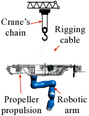
In pursuit of increased performance and safety in the field, cable-suspended aerial manipulators have been recently proposed[10, 11, 12]. One example is the crane-stationed cable-Suspended Aerial Manipulator SAM developed in DLR [13], see Fig. 1. External crane suspension allows the platform to be compact and to utilize new approaches in order to deal with the displacement of .

In the scope of this paper, we introduce a novel winch-based actuation integrated to the SAM and inspired by the cable-driven robotics [14, 15, 16]. By regulating the length of three suspension rigging cables connecting the SAM with the crane’s hook, the winch-based actuation compensates for the gravitational torque generated by robotic arm weight. In order to design a controller for this kinematically-redundant system, a number of challenges should be resolved. First of all, a closed-chain winch cabling in pair with attached robotic arm is modeled by Lagrangian constrained dynamics and mapped to the equal serial-chain coordinates describing the translational motion of the SAM base [17, 18, 19]. Secondly, the complex dynamics is simplified in order to find a reasonable trade-off between the system behavior description and equations that can be efficiently utilized in the controller. Further, a hierarchical whole-body controller with integrated admittance interface is adapted to the resulted kinematically redundant system extending our previous contribution [20] by adding capability of aerial base’s translation motion in the null space. The main aim of the controller is to perform two objectives with different priorities defined through the null-space: regulation of the robotic arm toward desired configuration and shifting system to the location with zero torque due to gravity. Both tasks are regulated under impedance-based control. Benefits and performance investigation of the introduced winch-based actuation under the designed control strategy are studied through experiments.
II The SAM Platform
II-A General description
The SAM platform serves for the conduction of safe in a complex industrial environment. During the operation, the system is suspended to the carrier, e.g., mobile crane, that brings the system to the operational point and compensates for total gravity. Attached to the bottom of the platform, a redundant 7 degrees of freedom () robotic arm KUKA LWR 4 performs the manipulation task while two actuation units, propeller propulsion and winches, keep the aerial base close to the motionless state, see Fig. 2(a). The former actuation contains small safe propellers that can generate the propeller-based omnidirectional wrench which is insufficient to counteract gravity but which can dampen oscillations caused by even small disturbances as was shown in [21].
In order to further enhance the manipulation and stabilization performance of the system, in this work, we concentrate on the integration of the second actuation system, i.e., winches. It allows controlling the platform displacement relative to the winch suspension point via changing the length of the three rigging cables and, consequently, cable tension distribution. The winch actuation is only switched on after the SAM reaches the desired operational point and dampens oscillations by propeller propulsion.
II-B Design of the winch-based actuation
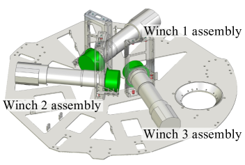
The winch-based actuation contains three embedded winches each of which can control the length of the rigging cable that suspends the SAM platform to the crane’s hook. Each winch is installed inside the platform (Fig. 2(b)) and based on a motor assembly, that contains Maxon RE50 DC-motor, a planetary gearhead with a reduction ratio of 343/8, a 3 channel high precision encoder HEDL 9140 with 500 counts per turn, and a static brake AB 44. The regulation of each assembly is performed by controller EPOS4 compact 50/5 CAN with integrated motion controller based on the encoder feedback.
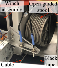
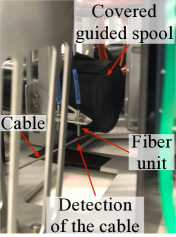
A guided spool is attached to the gearhead output shaft, at which the controlled steel cable is wounded, see Fig. 2(c). The cable length varies from 0.5 to 1.3 meters. The sagging of the rigging cables within this range is unattainable even with horizontally stretched robotic arm. To keep length within this range, an optical fiber sensing system from Keyence is used. When the cable length exceeds the precalibrated limit range, the light beam of the fiber unit is interrupted as shown in Fig. 2(d), and the motor is paused.
Three motor assemblies are integrated into a single communication Controller Area Network bus composed of can-high and can-low signals and terminated by a 120 resistance on both sides. The communication is established via the higher layer CANopen protocol with a transmission rate of 1 Mbits/s.
Onboard flight control computer () with deployed QNX Neutrino Real-time Operating System is utilized to establish the Leader/Followers communication between and EPOS4 controllers, a special library to manage the CANopen stack was developed. It allows operation of the winches with the desired rotational angle as an input.
III Modeling
In this section, we derive the SAM model that will be further used for control strategy formulation. We consider the case when the SAM is suspended to a fixed crane. To gain better intuition behind the complex system, first, we investigate a planar case, and further generalize it.
III-A Coordinate frames and main assumptions
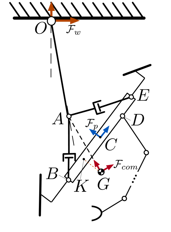
The SAM can be represented as a double pendulum suspended to the crane jib tip, (Fig. 3(a)). The length of the first link, , is equal to the length of the crane chain, . We assume that the hook mass, , is concentrated at point . The second link consists of two objects: SAM platform and manipulator. Rigging cables, and , are always under tension, so they can be represented as rigid links without sagging. Both tips of each cable, i.e., points , , , are modeled as rotational joints. The length of the rigging cables can be controlled and initially is equal to each other. The robotic arm is rigidly attached to the platform at point .
Let us introduce the following coordinate frames. The inertial frame centered in the suspension point such that its vertical axis is opposite to downward gravity direction. The platform frame is aligned with the platform principal axes and placed at platform center, point . A frame is located at the total (platform and manipulator), at point .
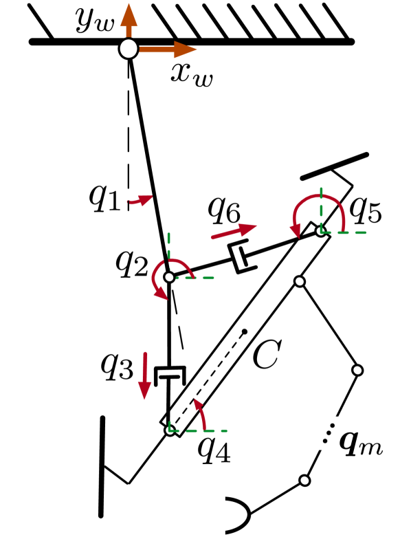
III-B Dynamics formulation
The SAM planar model can be represented as a closed-chain system, see Fig. 3(b). The corresponding state can be described by the vector of redundant generalized coordinates . Here, is the vector of redundant winch-related joints including passive revolute joints, , and active prismatic joints, and , corresponding to the winch cable lengths, is the vector of the manipulator joint angles.
Since our model contains a closed chain , the system dynamics is partially constrained. Applying Lagrangian formulation, the equation of motion can be written as111The term is omitted since we do not measure the external wrench applied to the system. In interaction tasks, a force torque sensor at the end-effector might be utilised for this purpose.:
| (1) |
where is the symmetric positive definite inertia matrix, contains the centrifugal/Coriolis terms, is the gravity vector, and is a vector of the joint torques. Let us denote by a number of passive and active s of the winch-related joints which cannot be controlled independently because of the system constraints corresponding to the closed chain. Thus, there are only s along which platform can move using winch-based actuation. Then, is a Pfaffian matrix, and are Lagrange multipliers that parametrize the interaction forces acting along the constraints.
In order to impose holonomic constraints on the system dynamics, let us formulate a vector loop-closure equation that represents forward kinematics of the point :
| (2) |
Projecting (2) on and axes of the inertial frame and taking its time-derivative, we can derive two constraints in the Pfaffian form . In order to resolve constraints and reduce the dimension of the state , we apply a coordinate transformation. To this end, let us define a vector of constraint-consistent independent generalized coordinates as follows: . Then, the relation between and can be written as where such that .
As we mentioned above, there are s along which the platform can perform motion using winch system, i.e., . In terms of practical application, we are interested in more intuitive motion directions, e.g., platform horizontal , vertical , and rotational motions w.r.t. the inertial frame. To this end, by utilizing (2), it is possible to express winch parameters as vector of the platform state . Thus, we can define an equal state vector of feasible motions as , such that . Vector corresponds to the equal serial-chain representation of the independent generalized coordinates defining the closed-chain dynamics.
After coordinate transformation, the constrained dynamics (1) can be formulated as unconstrained one in terms of :
| (3) |
Here, , , , and . Vector of generalized torques applied to the serial dynamics (3) can be defined as , where is a torque applied to the pendulum first joint, is a vector of control inputs applied to the joints corresponding to the platform motion, and are torques applied to the joints of the robotic arm. For more details on , , the reader is referred to [22, 23, 24].
III-C Reduced model for control design
Since winches cannot affect the motion of the platform around the yaw, a 3D case might be represented as two decoupled planar dynamics similar to the considered above. Therefore, the first joint of the double pendulum can be modeled by spherical joint, tips of the rigging cables can be modeled as universal joints with 2 s at each fixation point, and three closed-chain loops provide 9 constraint equations. The platform can be moved by winch-based actuation in the space along 3 translational and 2 rotational s corresponding to the roll and pitch of the platform.
In the case, when oscillation damping controller is applied to the system [21], the dynamics of the pendulum joints ( for planar case) can be neglected, and corresponding pendulum joint angles will be defined over time only by gravitational torque depending on whether or not the system is under the suspension point. Moreover, the winch-based actuation contains only three actuated joints, so we should select three out of five s that we aim to control. In our case, translational motion is of main interest. Indeed, we can neglect by platform rotational dynamics since we can generate only such cable lengths that nullify platform tilting angles while keeping desired platform displacements as will be shown in IV-D. Thus, the winch-based actuation allows translational motions of the platform w.r.t. the suspension point in order to counterbalance displacement and, consequently, to nullify pendulum joints. To this end, we define a reduced feasible configuration which contains only joints responsible for the system location and robotic arm end-effector pose as , here m = 7 for redundant robotic arm.
Based on the aforementioned assumptions, the system dynamics can be formulated in terms of the s which will be accessed by the controller as follows:
| (4) |
Here, , and all elements with subscript “” correspond to the reduced dynamics.
IV Control Approach
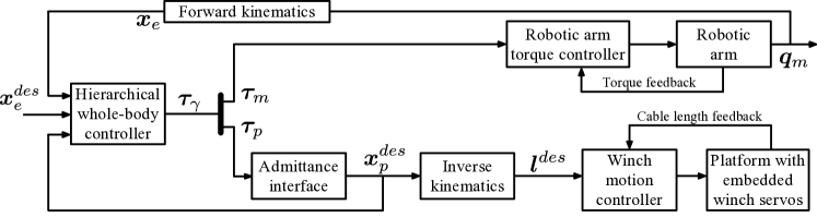
In order to regulate the defined state , in this chapter we adapt the hierarchical impedance-based whole-body controller [25, 26, 27], see Fig. 4. As input, we set the desired pose of the end-effector, , while desired horizontal terms of the system , , are set to zero during the whole operation. The whole-body impedance-based controller produces the desired generalized torques for the robot joints, , and joints of the platform, . The robotic arm is directly torque-controlled and provides the end-effector position, , as an output. The platform with integrated winches on another hand is kinematically controlled. To this end, we first transform the desired generalized torques to the required motion along platform joints, , by virtue of admittance interface, and further we use inverse kinematics () to map it to the desired cable lengths. In parallel, is used in the controller in order to update the location of the resulted system . In the following subsections, all aforementioned sub-blocks will be considered in detail.
IV-A Hierarchical decoupling and task space definition
Let us define the following control tasks for our system:
-
1.
The main task for aerial manipulator is to change end-effector Cartesian pose, , expressed in the inertial frame toward desired value, . Let us define configuration of the end-effector in terms of as , then our control goal is to provide: .
-
2.
The second task is to neutralize gravitational torque by keeping system , , under suspension point. Let us define the model location in inertial space as , then our control goal is to keep horizontal components of this vector, i.e., and as zeros.
-
3.
The last task is injection of additional damping to any robotic arm joint (we chose the 3rd one, i.e., elbow). This task is introduced for further convenience.
It is worth mentioning, that in real mission, the robotic arm is under remote operator control [28], so the second task should have less priority [29], and it should not interrupt the first (main) one. The third task has the least priority.
Following the task space definition, we can define task velocities:
| (5) |
here is the body velocity of the end-effector, is the vector of translational velocities of model , is the velocity of the robotic arm elbow joint. Besides, for , i.e., , , and are corresponding Jacobian matrices that have a full row rank.
In order to avoid interference between tasks, we need to decouple the task velocities at the acceleration level. To this end, dynamically consistent null-space projectors [30, 25] have been used to dynamically decouple original Jacobian matrices in (5) as follows:
Then, we can formulate corresponding hierarchically decoupled task-space velocities as follows:
| (6) |
Here, indicates the vector of the new local decoupled space velocities, and is the extended Jacobian matrix that maps generalized velocities to the task velocities . Note that is invertible due to added 3rd task.
The new set of coordinates allows to receive hierarchically decoupled motion dynamics of the system (4):
| (7) |
where contains decoupled task inertias, and is transformed Coriolis-centrifugal matrix.
IV-B Impedance whole-body control law formulation
Since all tasks exploit the same s, a hierarchical whole-body controller is applied in order to ensure that the main task is fulfilled without being disturbed by the second and third. The control law is formulated as follows:
| (8) |
Here is the control force (body wrench) for the th task before being projected in the null space, and is applied in order to decouple task dynamics at the velocity level. It compensates for the off-blockdiagonal submatrices of the Coriolis-centrifugal matrix : , .
To accomplish the desired tasks and achieve compliant behaviour on all hierarchical levels, the Cartesian impedance control is exploited [31]:
| (9) |
Here, the matrices are positive definite gain matrices (subscripts , stand for positional stiffness and damping, respectively), is the pose error between desired and current pose, and is the velocity of the i-th task in (5).
Formulated control law (8) can be applied directly to our system for execution of all control tasks. However, the winch servos are position-controlled, so additional transformation is required.
IV-C Admittance interface
Each winch takes the desired length of cable as an input signal. In order to operate the whole system at the torque level, the admittance interface was adapted [27, 32]. It takes commanded forces in joints as input to a virtual system with desired dynamics and produces the platform displacements as output. Exploitation of such an interface implies utilising the high gain motion controller for the winch actuation which can perfectly realize desired admittance dynamics despite external and internal disturbances, so no high-computational forward kinematics for cable-length feedback [33] from winch servos is utilized as shown in Fig. 4.
Passing through the admittance interface with desired dynamics, corresponding displacement, , is defined:
| (10) |
where are positive inertia and damping diagonal matrices describing desired system dynamics.
Assuming that for embedded high-gain motion controller , the overall system dynamics (4) can be rewritten:
| (11) | ||||
Here, and are the inertia and Coriolis couplings between platform and manipulator which are submatrices of and . Following the [27], control law (8) should be extended with an additional term to remove coupling effect between manipulator and platform in (11) due to admittance dynamics.
As a final step, the calculated displacement, , should be transformed to the rigging cable lengths.
IV-D Inverse kinematics
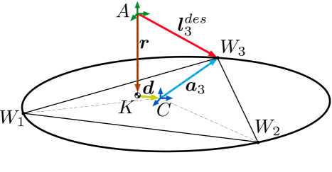
In order to control joints via the lengths of the cables, the inverse kinematics for the rigging cable suspension is formulated. As shown in Fig. 5, the following vector loop can be constructed [14]: Here, is the length of the cable. Constant vector represents the location of the th cable start point, , w.r.t. the platform geometric center, point . Vector connects the suspension point with point which indicates the system , point , projected at the platform plane, see Fig. 3(a). Displacement between and is defined by vector . is a rotation matrix representing orientation of the platform via roll and pitch angles. Since it is in our interests to keep these angles as zeros, we impose such that . Thus, presented calculates such lengths which ensures horizontal components under the suspension point while keeping horizontal orientation of the platform.
V Experimental Validation
In order to investigate the winch system performance and validate the proposed control law (8), we conducted two experiments. In both experiments, the platform was manually stabilized before the start, and propellers were used to keep the constant yaw angle without applying oscillation damping. The SAM dynamics (11) for reduced state was simulated onboard using the dynamics library based on [34].
V-A Preprogrammed trajectory following
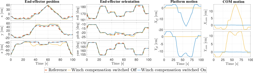
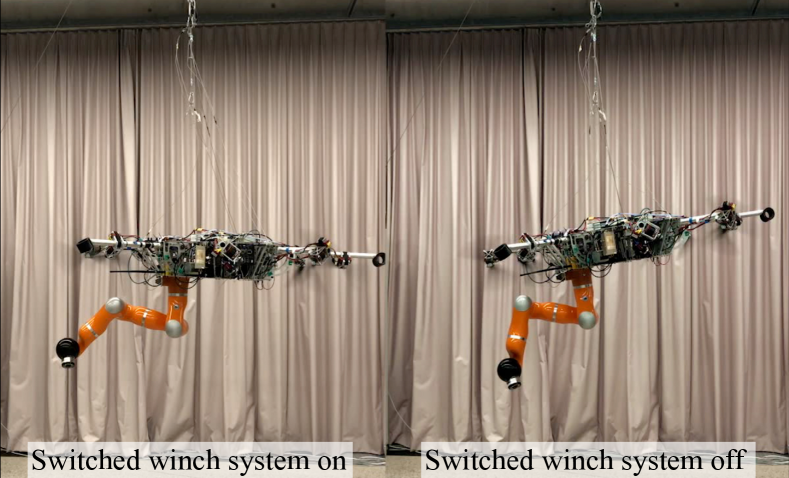
During the first experiment, the manipulator end-effector moved along a preprogrammed trajectory, see Fig. 6. Such a motion should force the system to tilt due to displaced under the gravity effect. We conducted this experiment twice with switching the winch system on and off in order to compare the behavior. As a result, with switched winch-based actuation on, the end-effector reached desired position while of the system remained under the suspension point keeping the platform horizontal. At the same time, the winch disabling led to the platform tilting.
Results of the first and second control tasks are shown in Fig. 7. Presented data is extracted directly from the real-time model based on (11). Since the model state does not take into account the tilting of the platform due to gravity, the real performance of the system with switched winches off for the first control task is even worse, see attached video for visual comparison.
The second task is also fulfilled. With active winches, the platform kept horizontal orientation, while corresponding terms of the had zero values. Compensation of the gravitational torque was performed by the platform motion. When we switched winches off and repeated the experiment, the result was the opposite.
V-B Pick and place of the cage
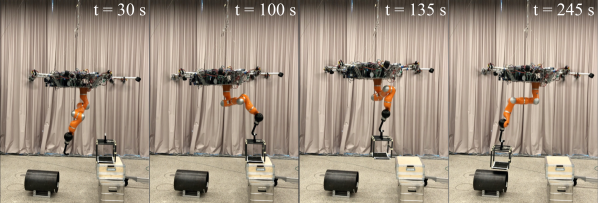
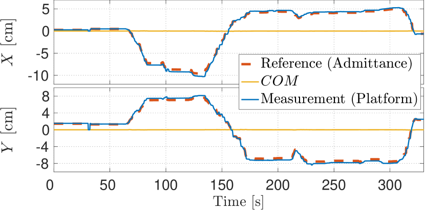
In order to validate the applicability of the total framework, the pick and place task was conducted, see Fig. 8. The task was to pick the empty cage from the metallic case and move it to the pipe. Such a cage might be utilised for transportation of mobile inspection robots. In this experiment, the end-effector was controlled remotely by an operator using a joystick with force feedback. It can be seen that during the whole mission, the platform kept its own orientation close to the horizontal. The winch-based actuation fully provided designed capabilities, i.e., in the horizontal plane was close to zero while the platform shifted in the horizontal plane in order to compensate for the disturbing gravitational torque, see Fig. 9. It is worth noting that the platform precisely followed the command of admittance interface with selected gains: , .
VI Conclusion
In this paper, we introduced the novel winch-based actuation for the cable-suspended aerial manipulator SAM. It helped to compensate for the disturbing gravitational torque by changing the length of suspension rigging cables. System closed-chain dynamics was transformed to equal serial-chain dynamics instantaneously feasible w.r.t. the defined holonomic constraints. It allowed to access the platform translational motion instead of the cable joints and to formulate two intuitive control tasks: to keep the desired pose of arm end-effector and to shift the system under the suspension point. Both tasks were regulated by the impedance hierarchical whole-body controller with integrated admittance interface and inverse kinematics for the position-controlled winch servos. Received results demonstrated the applicability of the proposed actuation system as well as control framework to the real scenarios for implementing complex missions. A further research could investigate the performance and energy cost optimization when both actuation systems are activated.
References
- [1] A. Ollero, M. Tognon, A. Suarez, D. Lee, and A. Franchi, “Past, present, and future of aerial robotic manipulators,” IEEE Transactions on Robotics, vol. 38, no. 1, pp. 626–645, 2021.
- [2] F. Ruggiero, V. Lippiello, and A. Ollero, “Aerial manipulation: A literature review,” Robotics and Automation Letters, vol. 3, no. 3, pp. 1957–1964, 2018.
- [3] H. B. Khamseh, F. Janabi-Sharifi, and A. Abdessameud, “Aerial manipulation—a literature survey,” Robotics and Autonomous Systems, vol. 107, pp. 221–235, 2018.
- [4] K. Kudelina, B. Asad, T. Vaimann, A. Rassolkin, A. Kallaste, and D. V. Lukichev, “Main faults and diagnostic possibilities of bldc motors,” in 2020 27th International Workshop on Electric Drives: MPEI Department of Electric Drives 90th Anniversary (IWED). IEEE, 2020, pp. 1–6.
- [5] J. D. Nath and W. K. Durfee, “Optimization and design principles of a minimal-weight, wearable hydraulic power supply,” in Dynamic Systems and Control Conference, vol. 58271. American Society of Mechanical Engineers, 2017, p. V001T30A002.
- [6] T. Haus, M. Orsag, and S. Bogdan, “Mathematical modelling and control of an unmanned aerial vehicle with moving mass control concept,” Journal of Intelligent & Robotic Systems, vol. 88, pp. 1–28, 03 2017.
- [7] M. J. Kim, J. Lin, K. Kondak, D. Lee, and C. Ott, “Oscillation damping control of pendulum-like manipulation platform using moving masses,” IFAC-PapersOnLine, vol. 51, no. 22, pp. 465–470, 2018.
- [8] A. Al Akhras, I. H. Sattar, M. Alvi, M. W. Qanbar, M. A. Jaradat, and M. Alkaddour, “The design of a lightweight cable aerial manipulator with a cog compensation mechanism for construction inspection purposes,” Applied Sciences, vol. 12, no. 3, p. 1173, 2022.
- [9] C. Pose, J. Giribet, and I. Mas, “Adaptive center-of-mass relocation for aerial manipulator fault tolerance,” IEEE Robotics and Automation Letters, vol. 7, no. 2, pp. 5583–5590, 2022.
- [10] R. Miyazaki, R. Jiang, H. Paul, Y. Huang, and K. Shimonomura, “Long-reach aerial manipulation employing wire-suspended hand with swing-suppression device,” IEEE Robotics and Automation Letters, vol. 4, no. 3, pp. 3045–3052, 2019.
- [11] A. Yiğit, M. A. Perozo, L. Cuvillon, S. Durand, and J. Gangloff, “Novel omnidirectional aerial manipulator with elastic suspension: Dynamic control and experimental performance assessment,” IEEE Robotics and Automation Letters, vol. 6, pp. 612–619, 2021.
- [12] M. A. Perozo, J. Dussine, A. Yiğit, L. Cuvillon, S. Durand, and J. Gangloff, “Optimal design and control of an aerial manipulator with elastic suspension using unidirectional thrusters,” in 2022 International Conference on Robotics and Automation (ICRA). IEEE, 2022, pp. 1976–1982.
- [13] Y. S. Sarkisov, M. J. Kim, D. Bicego, D. Tsetserukou, C. Ott, A. Franchi, and K. Kondak, “Development of sam: Cable-suspended aerial manipulator,” in International Conference on Robotics and Automation (ICRA). IEEE, 2019, pp. 5323–5329.
- [14] W. Kraus, V. Schmidt, P. Rajendra, and A. Pott, “System identification and cable force control for a cable-driven parallel robot with industrial servo drives,” in 2014 IEEE International Conference on Robotics and Automation (ICRA), 2014, pp. 5921–5926.
- [15] P. Bosscher, A. T. Riechel, and I. Ebert-Uphoff, “Wrench-feasible workspace generation for cable-driven robots,” IEEE Transactions on Robotics, vol. 22, no. 5, pp. 890–902, 2006.
- [16] J. Begey, L. Cuvillon, M. Lesellier, M. Gouttefarde, and J. Gangloff, “Dynamic control of parallel robots driven by flexible cables and actuated by position-controlled winches,” IEEE Transactions on Robotics, vol. 35, no. 1, pp. 286–293, 2018.
- [17] G. M. Freitas, A. C. Leite, and F. Lizarralde, “Kinematic control of constrained robotic systems,” Sba: Controle & Automacao Sociedade Brasileira de Automatica, vol. 22, pp. 559 – 572, 12 2011.
- [18] M. McGrath, D. Howard, and R. Baker, “A lagrange-based generalised formulation for the equations of motion of simple walking models,” Journal of biomechanics, vol. 55, pp. 139–143, 2017.
- [19] J. J. Murray and G. H. Lovell, “Dynamic modeling of closed-chain robotic manipulators and implications for trajectory control,” IEEE Transactions on Robotics and Automation, vol. 5, no. 4, pp. 522–528, 1989.
- [20] A. Coelho, Y. S. Sarkisov, J. Lee, R. Balachandran, A. Franchi, K. Kondak, and C. Ott, “Hierarchical control of redundant aerial manipulators with enhanced field of view,” in 2021 International Conference on Unmanned Aircraft Systems (ICUAS). IEEE, 2021, pp. 994–1002.
- [21] Y. Sarkisov, M. J. Kim, A. Coelho, D. Tsetserukou, C. Ott, and K. Kondak, “Optimal oscillation damping control of cable-suspended aerial manipulator with a single imu sensor,” in 2020 IEEE International Conference on Robotics and Automation (ICRA), 2020.
- [22] O. Ibrahim and W. Khalil, “Kinematic and dynamic modeling of the 3-rps parallel manipulator,” in Proceedings of the 12th IFToMM World congress, France, 2007, pp. 18–21.
- [23] C. A. My and V. M. Hoan, “Kinematic and dynamic analysis of a serial manipulator with local closed loop mechanisms,” Vietnam Journal of Mechanics, vol. 41, no. 2, pp. 141–155, 2019.
- [24] G. Zambella, G. Lentini, M. Garabini, G. Grioli, M. G. Catalano, A. Palleschi, L. Pallottino, A. Bicchi, A. Settimi, and D. Caporale, “Dynamic whole-body control of unstable wheeled humanoid robots,” IEEE Robotics and Automation Letters, vol. 4, no. 4, pp. 3489–3496, 2019.
- [25] A. Dietrich and C. Ott, “Hierarchical impedance-based tracking control of kinematically redundant robots,” IEEE Transactions on Robotics, vol. 36, no. 1, pp. 204–221, 2019.
- [26] C. Ott, A. Dietrich, and A. Albu-Schäffer, “Prioritized multi-task compliance control of redundant manipulators,” Automatica, vol. 53, pp. 416–423, 2015.
- [27] A. Dietrich, K. Bussmann, F. Petit, P. Kotyczka, C. Ott, B. Lohmann, and A. Albu-Schäffer, “Whole-body impedance control of wheeled mobile manipulators,” Autonomous Robots, vol. 40, no. 3, pp. 505–517, 2016.
- [28] J. Lee, R. Balachandran, Y. Sarkisov, M. De Stefano, A. Coelho, K. Shinde, M. J. Kim, R. Triebel, and K. Kondak, “Visual-inertial telepresence for aerial manipulation,” in 2020 IEEE International Conference on Robotics and Automation (ICRA), 2020.
- [29] A. Dietrich, C. Ott, and A. Albu-Schäffer, “Multi-objective compliance control of redundant manipulators: Hierarchy, control, and stability,” in 2013 IEEE/RSJ International Conference on Intelligent Robots and Systems. IEEE, 2013, pp. 3043–3050.
- [30] O. Khatib, “A unified approach for motion and force control of robot manipulators: The operational space formulation,” IEEE Journal on Robotics and Automation, vol. 3, no. 1, pp. 43–53, 1987.
- [31] S. Zhang and E. D. Fasse, “Spatial compliance modeling using a quaternion-based potential function method,” Multibody System Dynamics, vol. 4, no. 1, pp. 75–101, 2000.
- [32] M. Iskandar, G. Quere, A. Hagengruber, A. Dietrich, and J. Vogel, “Employing whole-body control in assistive robotics,” in IEEE International Conference on Intelligent Robots and Systems, 2019, pp. 5643–5650.
- [33] J.-P. Merlet and J. Alexandre-dit Sandretto, “The forward kinematics of cable-driven parallel robots with sagging cables,” in Cable-Driven Parallel Robots. Springer, 2015, pp. 3–15.
- [34] G. Garofalo, C. Ott, and A. Albu-Schaffer, “On the closed form computation of the dynamic matrices and their differentiations,” in IEEE/RSJ International Conference on Intelligent Robots and Systems (IROS), 2013, pp. 2364–2359.