1.2pt \contourlength1.0pt \watermark Accepted for presentation in: 2023 6th IEEE International Workshop on Mobile Terahertz Systems (IWMTS), Bonn, Germany, July 2023.
Phase-based Breathing Rate Monitoring
in Patient Rooms using 6G Terahertz Technology
Abstract
The 6G standard aims to be an integral part of the future economy by providing high-performance communication and sensing services. At terahertz (THz) frequencies, indoor campus networks can offer the highest sensing quality. Health monitoring in hospitals is expected to be an application site for these. This work outlines a monostatic phase-based system for breathing rate monitoring. Our feasibility study observes motion measurement accuracy down to the micrometer level. However, we also find that the patient’s pose needs to be considered for generalized applicability. Thus, a solution that leverages multiple propagation paths and beam orientations is proposed.
Index Terms:
6G, THz communications, monostatic sensing, patient monitoring, breathing rate tracking, random rough surfaces, ray-tracing, .I Introduction
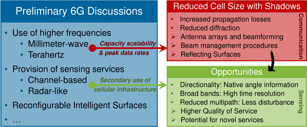
Mobile radio networks have recently expanded to the millimeter-wave (mmWave) domain with the advent of the 5G standard. The first networks launched operations in urban centers in the US [1] and test deployments of private campus networks, e.g., connecting manufacturing floors, are up and running [2]. Moreover, the first discussions about what 6G will be have already begun, see fig. 1. One of the goals of 6G is to ensure the market success of networks targeting such high frequencies by making it profitable to deploy the technology in the economy, such as in factories and hospitals.
This becomes feasible as the frequencies up to THz have risen to the spotlight to reliably provide ultra-high data rates and network capacity at low latency for industrial processes. Moreover, whereas carriers at mmWaves and beyond suffer from rather hostile propagation characteristics, they become ever more suitable for indoor sensing purposes in the scope of 6G joint communication and sensing (JCAS) [3]. THz signals offer superior spatial and temporal resolution than lower bands, such as microwaves, owing to their extremely wide bandwidths and short wavelengths, whereas also exhibiting excellent penetration capabilities compared to optical waves [4, 5]. Because THz radiation is non-ionizing and non-invasive, it is a safe choice for security screening and medical sensing applications [6]. As such, machines and processes can be stopped, altered, and (re-)started based on highly accurate sensor information conveniently acquired by the cellular network. This is of high interest to the health sector for monitoring patients and initializing measures autonomously [7].
Communication channels are widely in use to provision sensing services, e.g., the positions of connected user equipments, based on power, time, angle, and phase measurements [8]. The healthcare domain has witnessed the use of THz technology for various medical applications, including the characterization of tablet coatings, investigation of drugs, dermatology, oral healthcare, oncology, and medical imaging [9, 10]. There is a wide range of applications in the scope of patient health monitoring, such as human presence detection and tracking, gesture detection, fall detection, tremor monitoring, and tracking of respiration rate [11, 12]. 6G is expected to introduce radar-like sensing using co-deployed transmit and receive antennas on the base station (BS) side such that the network autonomously becomes perceptive of the activities in the vicinity, i.e., there is no need for the deployment of UEs [13]. As such, a comparison with the often-considered use cases of breathing rate estimation by tracking the thorax motion [14] is of interest to characterize the suitability of using THz channels in a monostatic fashion.
The remainder of this paper is structured as follows: Sec. II conceptualizes a THz phase-based patient monitoring system operating in a monostatic fashion. Afterward, Sec. III describes the ray-tracing-based methodology of this work. We then evaluate the feasibility of the proposed concept in Sec. IV. Sec. V concludes this work with an outlook on future work.
II Proposed Patient Monitoring System
In this section, we introduce a 6G THz-based system for the network-autonomous monitoring of hospital patient rooms for the example use case of breathing rate monitoring as follows.
II-A Breathing Motion Data Acquisition
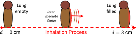
During the breathing process, the chest of a typical adult expands by up to for a deep breath, whereas a patient’s shallow breathing may also result in changes as small as [14]. These fine-grained motions with magnitude affect the radio environment, particularly the channel phase of the affected propagation paths [14, 15]. Using the complex-valued two-way channel estimate at time instances (initial state, e.g., lung deflated) and (altered state, e.g., partial inhalation), , the motion can be detected based on measuring a two-way phase difference , as follows [15]:
| (1) |
Leveraging information about the used frequency , the motion magnitude can be estimated using
| (2) |
where is the speed of light. The factor in eq. 2 transfers the measured two-way phase shift to a distance in dependence of the wavelength . Due to the 6G JCAS-compatible, monostatic approach using co-deployed transmit and receive antennas per transceiver (TRX), the coefficient of is introduced to derive a single-way phase change from .
In the previously described process, indicates a shortening of the propagation path between BS and patient, i.e., the chest expands. Using high signaling rates to attain the channel estimates, the whole inhalation process may be tracked step-by-step. Similarly, negative motion steps () are measured during the deflation process of the lung. Continuing the process indefinitely, a time series of fine motion steps is captured by the 6G TRX, thus allowing for the reconstruction of the overall chest movement as well as the breathing rate.
II-B Conquering Limitations by the Patient Pose
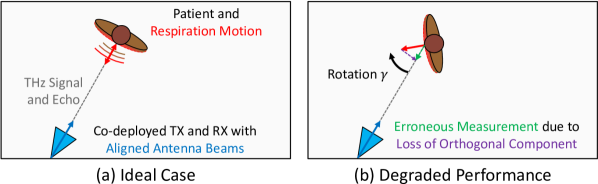
One of the implicit assumptions in Sec. II-A is that the thorax motion matches the propagation direction, i.e., the Poynting vector of the electromagnetic (EM) wave in 3D space, as illustrated in fig. 2 (a). However, if the user is rotated by , the breathing motion of the patient contains an orthogonal component that cannot be measured [15], see fig. 2 (b). As such, the motion magnitude measurement suffers from a systematic error such that
| (3) |
As a consequence, at rotation angles no motion can be observed because the motion is either fully orthogonal to the propagation path or the patient’s back is observed instead of the front side. The beam orientation-aided approach described in [15] has remedied this problem, however, assuming the receiver is mounted at the chest of the patient.
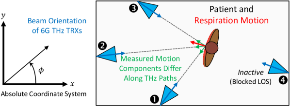
In the following section, we evolve the technique from [15] to the considered monostatic sensing scenario using multiple infrastructure nodes as shown in fig. 3. Nodes with have measured the motions using the antenna beam orientation tuples , which are carefully aligned to the patient’s torso. The definition of azimuth angle is depicted in fig. 3, whereas the elevation angle is defined from the x/y-plane towards the z-axis. As such, the beam orientation in space is as follows.
| (4) |
Patient motion can thus be matched to the direction vector
| (5) |
such that motion components along the two mutually orthogonal vectors have been lost. Therefore, the idea is to recover their coefficients, such that, e.g.,
| (6) |
They are recovered by solving the linear equation system of . Vector shall be determined from matrix and vector as follows.
| (7) |
| (8) |
Note that and . For brevity, eq. 8 defines for the case of . Note that may not be smaller for a unique solution. At last, the overall breathing motion is reconstructed using all elements contained in :
| (9) |
Thus, the sought-after breathing motion magnitude can be extracted using the Euclidean norm, i.e., by . As such, we have shown with eqs. 7, 8 and 9 how angle information from nodes (eq. 2) along with the phase changes of the corresponding channels (eq. 5) can be used to measure the fine motion irrespective of the patient’s pose, i.e., position and orientation in the patient room.
II-C Network Planning for Optimized THz Indoor Deployments
The above-proposed patient monitoring system in Secs. II-A and II-B relies on co-deployed TRXs, as depicted in fig. 3. However, depending on the room dimension, furnishing, and the position and rotation angle of the patient, they have to be mounted intelligently at suitable positions such that at least three paths exhibit line-of-sight (LOS) modality. In our earlier work [16], automatic network planning based on machine learning was developed and evaluated for sub- communication networks. There, all possible antenna positions were simulated beforehand via ray-tracing for subsequent use of clustering methods to identify the best local results. Afterward, they are combined into a network plan which suits the application requirements, such as the need for distinct propagation paths. This needs to be explored in future work.
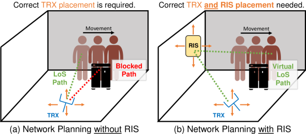
Moreover, the requirement for TRXs is not optimal due to costs. Considering the emerging topic of RISs, it could be reduced to just one if RISs are employed to provide virtual line-of-sight (VLOS) paths along well-selected reflection beams. Therefore, multipath propagation could be exploited as proposed in [17]. However, this adds a new dimension to the pre-deployment network planning, as illustrated in fig. 4. Whereas algorithms for the placement of RISs have already been proposed in the literature, e.g., in [18], they have to be altered for the previously described requirements. Particularly the planning overhead needs to be considered due to the dependency of the RIS placement on the TRX placement. Whereas the overhead for traditional network planning is in [16], with being the number of considered mounting positions, the planning of RIS-assisted deployments is in . In conclusion, previously possible automated network planning methods have to be extended by a pre-processing of possible position combinations for antenna and RISs to limit the number of required simulations.
III Methodology
This section details the methodology of this work. Sec. III-A describes the considered indoor scenario and gives details on the ray-tracing simulations. Afterward, Sec. III-B gives additional details on the signal processing exceeding the scope of Sec. II. Sec. III-C concludes this section with details on the evaluation in Sec. IV.
III-A Patient Room Scenario and Terahertz Ray-tracing
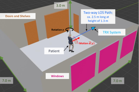
This work considers the indoor scenario depicted in fig. 5. For brevity, detailed descriptions of objects such as doors, cupboard, and glass windows are omitted as they can be found in [19]. The JCAS TRX is mounted at a height of . The patient, and thus, the breathing motion with magnitude , is initially perfectly aligned to the LOS propagation path (using ) with a length of to the patient body’s center point. In adapted scenarios the user is rotated such that the breathing motion is partially orthogonal instead of fully aligned to the LOS path. The angles are considered. To achieve perfect scattering in this work, the human body of the patient is attributed with perfect electric conductor-like properties. Otherwise, the performance of the system could be impaired.
The patient reflection-based channels between co-deployed transmitter (TX) and receiver (RX) are simulated for the above described scenario as follows. Horn antennas with approx. gain and E-plane half-power beamwidth (HPBW) are employed based on EM simulations with CST [20]. They are vertically polarized to optimize scattering effects and reduce scattering losses. Using a transmit power of , the patient reflection-based multipath channel is captured along the breathing inhalation motion of up to shown in figs. 6 and 5. At the patient is moved in steps of using the commercial ray-tracer Wireless Insite [21]. Moreover, we also leverage channel data at in steps of about using a THz-specific commercial ray-tracer [22]. In both cases, the requirement for motion steps smaller than between channel samples, i.e., a high sampling rate, is enforced to avoid EM wave-based phase ambiguities.
| Carrier | Parameter | Value/Range |
|---|---|---|
| Motion Trajectory | ||
| Rotation Angles | ||
| Number of Simulations | ||
| Motion Trajectory | ||
| Rotation Angles | ||
| Number of Simulations |
| Material | Type | ||||
|---|---|---|---|---|---|
| Plaster | Rough | 3.691 | 0.217 | ||
| PVC | Smooth | 2.788 | 0.069 | - | |
| Wood | Smooth | 1.734 | 0.073 | - | |
| Glass | Smooth | 6.656 | 0.539 | - |
We now give some further simulation details, in particular, for the simulations. Tab. II enlists the empirical parameters of the object materials employed in our modeling approach. As only the walls and ceiling are made of rough plaster, the statistical roughness parameters, such as the standard deviation of height () and surface correlation length (), are also provided. The Beckmann-Kirchhoff (B-K) approach is utilized to approximate the attenuation caused by surface roughness in a specular direction of reflection, as well as diffuse scattering in non-specular directions. It is implemented using a tile size of and tiles, as in [23]. The simulations further take into account state-of-the-art vector network analyzer (VNA) [5] based channel measurements for calibration of the ray-tracer [22]. Abiding the WR-3.4 extenders’ -restricted peak dynamic range, multipath components incurring higher losses are ignored.
III-B Additional Processing Methodology
The result of the ray-tracing simulations are complex-valued channel impulse responses for each state along the patient’s motion. To extract and compare the channel phases over time, the CIR vector acquired at each time instance is first transformed to the frequency-domain using the non-uniform discrete Fourier transform (NUDFT), thus allowing for a similar processing as in [15]. Accordingly, a phase unwrapping operation is conducted for each frequency-based time series. Last, the mean channel phase over all frequencies is estimated per time instance resulting in one channel phase estimate per CIR. Note that the process could be refined if the TRX leverages information about the baseline scenario, i.e., the patient room without patient inside.
III-C Evaluation Methodology
This work will first investigate the feasibility of the monostatic breathing rate monitoring in Sec. IV-A for the ideal case as sketched in fig. 2 (a). We will look into the measured motion steps between consecutive time instances along an inhalation process, thus representing any respiration pattern, and compare to the expected value. This applies to the data provided by both ray-tracers, i.e., at with a step size of and at in steps of about ().
Afterward, in Sec. IV-B we consider -rotated patients which are expected to impact the practical performance, thus motivating our proposed reconstruction technique. Hence, we investigate the reconstructed overall chest motion which arises from continuous integration of the detected motion steps . The ensuing trajectory of the patient’s chest during the inhalation process is evaluated for the considered four rotation angles of up to , cf. fig. 5 for the rotation definition, and compared to the performance for the non-rotated patient.
IV Evaluation
This section first studies the feasibility of channel phase-based patient breathing rate monitoring using a 6G THz TRX in a monostatic fashion as in the scope of JCAS. Afterward, a sensitivity analysis of the impact of the user rotation is conducted as described in Sec. III-C.
IV-A Feasibility Study of THz Phase-based Patient Monitoring
We first consider the measured motion steps between consecutive channel estimates for the simulation data, as depicted in fig. 7. The motion steps observed oscillate around the underlying actual patient motion sampled about every . The absolute error does not exceed . Therefore, a promising accuracy is found. Moving on to the simulation data with channel estimates available every , as provided in fig. 8. Here, we observe a deviation of up to in the worst case, whereas it is typically below . The error, however, seems more like a constant offset for this y-axis resolution. One can conclude from this that the sensing at the lower frequency might be less suitable, e.g., due to a different constellation of multipath components impacting the measurements. Nonetheless, the error is orders of magnitude smaller than the motion, thus still highlighting that frequencies above are suitable for the proposed monostatic monitoring of patients.
IV-B Sensitivity Analysis: Impact of Patient Pose
In the second part of the evaluation, we consider the impact of the user rotation angle on breathing motion monitoring. For the simulation data depicted in fig. 9, we find that the overall trajectory measurement is significantly distorted if the user has a non-ideal pose. In the worst case of the behavior is as expected in Sec. II-B, i.e., no motion is observed. Thus, the need for our proposed technique to reconstruct the lost motion information is confirmed. The trajectories observed for are furthermore mixed up and do not match the behavior predicted by eq. 3. This could be due to multipath distorting the channel estimates. Using the carrier, the motion trajectories in fig. 10 more closely resemble a linear function with the slope depending on . Here we find that small pose changes of, e.g., up to rotation do not significantly impact the breathing motion tracking. As such, the system will not require an otherwise motionless patient, e.g., monitoring during sleep could be feasible. Nonetheless, for generalization of the system in terms of, e.g., patient pose (position and rotation) and room layout, a tracking enhancement using the concept derived in Sec. II is necessary.
V Outlook on Future Work
In this study, we investigated the use of 6G networks for health monitoring purposes. A concept for breathing rate tracking in patient rooms was introduced using THz channel phase information from monostatic sensing. The conducted case study revealed that the motion of the patient’s chest can be measured with an error of less than at , but only if the motion is aligned with the LOS path. This work outlined in detail how multiple propagation paths, together with bearing information, can be used to reconstruct lost orthogonal motion components. As such, our ongoing work aims to confirm this by facilitating low-cost RIS-based VLOS propagation paths. A novel network planning scheme shall be developed afterward to mount the RISs at optimized positions such that any patient pose can be accommodated.
Acknowledgment
This work has been partly funded by the German Federal Ministry of Education and Research (BMBF) in the course of the 6GEM Research Hub under the grant number 16KISK038. Further funding has been received from the German Research Foundation (DFG) Project-ID 287022738 TRR 196 for Projects M01 and S04. Additional support has been given by the Ministry of Economic Affairs, Industry, Climate Action, and Energy of the State of North Rhine-Westphalia (MWIKE NRW) along with the Competence Center 5G.NRW under the grant number 005-01903-0047. This work has also received funding from the program Netzwerke 2021, an initiative of the Ministry of Culture and Science of the State of North Rhine-Westphalia (MKW NRW).
References
- [1] Aurora Insight Inc., “Taking a closer look at 5G mmWave deployment strategies.” [Online]. Available: https://aurorainsight.com/taking-a-closer-look-at-5g-mmwave-deployment-strategies (Accessed 2023-03-18).
- [2] Fraunhofer IPT, “5G-industry campus Europe.” [Online]. Available: https://5g-industry-campus.com/infrastructure (Accessed 2023-03-18).
- [3] C. Chaccour et al., “Seven defining features of terahertz (THz) wireless systems: A fellowship of communication and sensing,” IEEE Commun. Surv. Tutor., vol. 24, no. 2, Jan. 2022.
- [4] F. Sheikh, A. Prokscha, J. M. Eckhardt, T. Doeker, N. A. Abbasi, J. Gomez-Ponce, B. Sievert, J. T. Svejda, A. Rennings, J. Barowski, C. Schulz, I. Rolfes, D. Erni, A. F. Molisch, T. Kürner, and T. Kaiser, “THz measurements, antennas, and simulations: From the past to the future,” IEEE J. Microwaves, vol. 3, no. 1, Jan. 2023.
- [5] F. Sheikh, Y. Zantah, A. A. Abbas, and T. Kaiser, “See-through soil measurements at 300 GHz,” in Proc. IEEE IRMMW-THz, Aug.-Sep. 2022.
- [6] M. Gezimati and G. Singh, “Terahertz imaging and sensing for healthcare: Current status and future perspectives,” IEEE Access, vol. 11, Feb. 2023.
- [7] S. Nayak and R. Patgiri, 6G Communication Technology: A Vision on Intelligent Healthcare. Singapore: Springer, Jan. 2022, ch. 1.
- [8] S. Häger, N. Gratza, and C. Wietfeld, “Characterization of 5G mmWave high-accuracy positioning services for urban road traffic,” in Proc. IEEE VTC-Spring, Jun. 2023.
- [9] A. Y. Pawar et al., “Terahertz technology and its applications,” Elsevier J. Drug Invention Today, vol. 5, no. 2, Jun. 2013.
- [10] J. Shumaila et al., “Medical sensors and their integration in wireless body area networks for pervasive healthcare delivery: A review,” IEEE Sensors J., vol. 22, no. 5, Mar. 2022.
- [11] Y. Ma et al., “WiFi sensing with channel state information: A survey,” ACM Comput. Surv., vol. 52, no. 3, Jun. 2019.
- [12] D. Haider et al., “Utilizing a 5G spectrum for health care to detect the tremors and breathing activity for multiple sclerosis,” Wiley Trans. Emerging Telecommunications Technologies, vol. 29, no. 10, Jul. 2018.
- [13] A. Zhang et al., “Perceptive mobile networks: Cellular networks with radio vision via joint communication and radar sensing,” IEEE Vehicular Technology Mag., vol. 16, no. 2, Jun. 2021.
- [14] S. Tewes et al., “IRS-enabled breath tracking with colocated commodity WiFi transceivers,” IEEE IoT J., Dec. 2022.
- [15] S. Häger, S. Böcker, S. Jamali, T. Reinsch, and C. Wietfeld, “A novel system architecture for small-scale motion sensing exploiting 5G mmWave channels,” in Proc. IEEE Globecom Wkshps, Dec. 2021.
- [16] C. Bektas, S. Böcker, B. Sliwa, and C. Wietfeld, “Rapid network planning of temporary private 5G networks with unsupervised machine learning,” in Proc. IEEE VTC-Fall, Sep. 2021.
- [17] S. Häger, S. Böcker, and C. Wietfeld, “3D self-motion tracking services: Coalescence of mmWave beam orientations and phase information,” in Proc. IEEE FNWF, Oct. 2022.
- [18] M. El-Absi, A. Al-Haj Abbas, and T. Kaiser, “Chipless RFID tags placement optimization as infrastructure for maximal localization coverage,” IEEE J. Radio Frequency Identification, vol. 6, Jul. 2022.
- [19] F. Sheikh, B. Salah, D. Lessy, and T. Kaiser, “Unexplored aspects in THz ray-tracing,” in Proc. IEEE IWMTS, Jul. 2021.
- [20] Dassault Systèmes SE, “CST Microwave Studio.” [Online]. Available: www.cst.com (Accessed 2023-03-18).
- [21] Remcom Inc., “Wireless InSite.” [Online]. Available: www.remcom.com/wireless-insite-em-propagation-software (Accessed 2023-03-18).
- [22] The Mobile THz Company UG, “Photorealistic THz ray-tracer.” [Online]. Available: www.themobilethzcompany.com (Accessed 2023-03-18).
- [23] F. Sheikh, Y. Gao, and T. Kaiser, “A study of diffuse scattering in massive MIMO channels at terahertz frequencies,” IEEE Trans. Antennas and Propagation, vol. 68, no. 2, Feb. 2020.