Delving into the anisotropic interlayer exchange in bilayer CrI3
Abstract
Bilayer CrI3 attracted much attention owing to peculiar switching between the layered ferromagnetic and antiferromagnetic order upon stacking alternation. This finding pointed out the importance of the apparently small interlayer exchange, yet, existing literature addresses only its isotropic part. To fill this gap, we combine the density functional theory with Hamiltonian modeling to examine the anisotropic interlayer exchange in bilayer CrI3 – Dzyaloshinskii-Moriya (DMI) and the Kitaev interaction (KI). We develop and apply a novel computational procedure that yields the off-diagonal exchange matrix elements with accuracy. Inspecting two types of bilayer stacking, we found a weak interlayer KI and much stronger DMI between the sublattices of monoclinic bilayer and their complete absence in rhombohedral bilayer. We show how these anisotropic interactions depend on the interlayer distance, stacking sequence, and the spin-orbit coupling strength and suggest the dominant superexchange processes at play. In addition, we demonstrate that the single-ion anisotropy largely depends on stacking, increasing by 50% from monoclinic to rhombohedral structure. Remarkably, our findings prove that iodines, owing to their spatially extended orbitals featuring strong spin-orbit coupling, are extremely efficient in mediating DMI across the van der Waals gap in two-dimensional magnetic heterostructures. Given that similar findings were previously demonstrated only in metallic multilayers where the DMI shows a much longer range, our study gives promise that the chiral control of spin textures can be achieved in two-dimensional semiconducting magnetic bilayers whose ligands feature strong spin-orbit coupling.
I Introduction
Since the long sought discovery of two-dimensional (2D) magnets finally happened with CrI3 and Cr2Ge2Te6 Huang2017Jun ; Gong2017Jun , a large stream of scientific efforts has been directed towards achieving new capabilities with magnetic van der Waals (VdW) heterostructures Klein2018Jun ; Song2018Jun ; Wang2018Jun ; Gibertini2019May ; Soriano2020Sep . Given the diversity of 2D materials, there is a profusion of possible magnetic VdW heterostructures that offer endless possibilities. Yet, to find intriguing phenomena, one doesn’t need to look any further from the two layers of CrI3. So far, the magnetic properties of bilayer CrI3 are manipulated by electric fields Huang2018Jul ; Morell2019Feb , electrostatic dopingJiang2019Apr , pressure Song2019Dec , and twisting Xu2022Feb . In addition, theoretical studies proposed to switch the direction of magnetization in one of its layers by spin-orbit torqueDolui2020Mar and predicted the magnetic photogalvanic effectZhang2019Aug , magnetic polarons Soriano2020Jan , and magnetoelectric response in bilayer CrI3Lei2021Mar . Yet, to efficiently exploit the possibilities offered by bilayer CrI3 in new concept devices, one has to truly understand the mechanism of the exchange coupling between the layers.
Monolayer CrI3 is composed of chromium atoms arranged in a honeycomb lattice surrounded by edge–sharing iodine octahedra. Below the Curie temperature the spins on Cr atoms are parallel and the monolayer CrI3 is a ferromagnet (FM) with an out-of-plane magnetization Lado2017Jun ; Besbes2019Mar ; Kashin2020Mar . The magnetic anisotropy energy (MAE), that is absolutely necessary for the long-range magnetic order to persist in 2D crystals at finite temperaturesMermin1968 , emerges in CrI3 from an interplay between the single-ion anisotropy (SIA) and the two-ion anisotropy (TIA) occurring between the nearest neighbors Cr ions Lado2017Jun ; Xu2018Nov . The TIA is usually derived within the generalized Heisenberg-Kitaev model and gives rise, in addition to the conventional isotropic Heisenberg exchange, to the Kitaev exchange and to the symmetric pseudo-dipolar interaction, depending on the bond-orientation. These terms, which we will generally label as ”Kitaev-like interaction” (KI), refer to the traceless symmetric part of the most general expression for bilinear spin-spin interactionsMoriya1960Oct and cooperate with dipole-dipole interaction in shaping the total magnetic anisotropyevans2020prb . Like SIA, the KI in CrI3 comes mostly from the spin-orbit coupling (SOC) on iodine atoms. MAE scales with the ligand SOC strength, being instrumental to CrI3 showing a higher Curie temperature () than the isostructural CrBr3 and CrCl3, whose ligands feature much weaker SOC than iodinesWebster2018Oct ; Lu2019Nov ; Xue2019Dec ; Lu2020Sep . Besides SIA and KI, SOC can give rise to the Dzyaloshinskii-Moriya interaction (DMI). However, the presence of an inversion center in the nearest neighbor Cr-Cr bonds imposes that this antisymmetric part of the anisotropic exchange is exactly zero. On the other hand the DMI is allowed between the next-nearest Cr neighbors and, although being tiny, it can play an important role in gaping the magnon spectraJaeschke-Ubiergo2021May .
In addition to magnetic properties that bilayer CrI3 inherits from its constitutive layers, the interlayer exchange has proven extremely important as it can affect the direction of layers’ magnetizations. It is an order of magnitude weaker than the intralayer exchange, but the possibility to tune it via stacking alternations made it a subject of numerous studies. For example, if we adopt the stacking from bulk CrI3 that crystallizes either in rhombohedral (the low temperature or LT phase, space group) or monoclinic lattice (the high temperature or HT phase, space group) McGuire2015Jan , we end up with two different bilayer structures that we refer to as the LT and the HT structure (Fig. 1a-b). Here the theoreticalSivadas2018Dec ; Jang2019Mar ; Jiang2019Apr ; Soriano2019Sep ; Kong2021Oct and experimentalLi2019Dec studies agree: the LT stacking favors the FM ordering of layers’ magnetizations, whereas the HT stacking leads to layered antiferromagnetic (AFM) order. However, being realized through (at least) two iodines, the interlayer Cr-Cr coupling is mostly of super-superexchange type, which makes its microscopic description complicated due to a high number of relevant hopping processesKe2021Jan ; Song2022Dec .
In bilayer CrI3 studies galore the interlayer exchange is most often considered isotropic. This is a reasonable assumption, given that the bilayer CrI3 lattice is centrosymmetric and thus the DMI is forbidden, whereas the KI, if nonzero, is usually very small. However, the strict constraints imposed on DMI by the global symmetry of the structure by no means forbid the DMI to appear locally, between the specific neighbors. Moreover, if the DMI exists between the specific neighbors and the global symmetry constraints are somehow removed – the macroscopic DMI can emerge as well. New studies warm up such expectations showing that skyrmions – topologically protected particle-like spin textures that usually appear as a consequence of DMI – can be induced via moire magnetic exchange interactions in twisted bilayer CrI3Akram2021Aug ; Xu2022Feb ; Yang2023Apr . Speaking of interlayer DMI in general, Vedmedenko et al.Vedmedenko2019Jun proposed the atomistic model that predicts the formation of global chiral spin textures due to interlayer DMI between the ferromagnetic layers coupled through a nonmagnetic spacer. Recently, chiral control of spin textures is experimentally achieved in ferromagnetic TbFe/Pt/Co thin films, where the out-of-plane magnetization of TbFe is DMI-coupled with the in-plane magnetization of CoAvci2021Oct . In this multilayer system the interlayer DMI is strong because the Pt atoms carry the conductive electrons that feature strong SOC. Having this in mind, the question is whether the iodine ligands, that also have considerable SOC, can play the role of DMI-mediator in bilayer CrI3. Moreover, having in mind the importance of KI in monolayer CrI3, how strong is the interlayer KI in bilayer CrI3?
We present a theoretical study that combines the density functional theory (DFT) and Hamiltonian modeling in calculating the anisotropic part of the interlayer exchange in bilayer CrI3. The manuscript is organized as follows: we start by presenting the employed computational approach in Subsection II.1 and describe the model Hamiltonian that expresses the coupling between two perpendicular spins in Subsection II.2. The ability of the perpendicular-spins model to capture the changes in DFT band energies is demonstrated in Subsection II.3. The validity of the model is extended to describe the coupling between fully magnetized layers in Subsection II.4, where we reveal a considerable DMI and an order of magnitude weaker KI between the sublattices of bilayer CrI3. We demonstrate how both DMI and KI depend on structural transformations and the SOC strength in Subsection II.5, suggesting possible superexchange mechanisms governing these interactions. Finally, in Section III we summarize the study by proposing a 2D magnetic heterostructure that should be a suitable platform for realizing the interlayer DMI coupling of layers’ magnetizations, similar to that experimentally achieved in metallic thin films.
II Results
II.1 Computational approach
We model the bilayer CrI3 by stacking two CrI3 layers in rhombohedral (LT) and monoclinic (HT) sequences (Fig. 1). The structural details and computational parameters of DFT calculations are given in the Section IV. In order to study the coupling between the two spins from different layers, we need to isolate them from the rest of the magnetic environment. To solve this problem, we use the supercell and replace by Al all the Cr atoms except the two inspected ones (Fig. 1c). Al, like Cr, is trivalent so it doesn’t perturb much the surrounding iodine ligand field. Therefore, the two remaining Cr atoms end up embedded into nonmagnetic crystalline environment that is reminiscent of that in bilayer CrI3. To check the validity of the atomic replacement method, we calculated the SIA and the intralayer nearest-neighbor exchange tensor of monolayer CrI3 and compared the results to those obtained with the reference four-state method Xiang2012Dec in Supplementary Information.
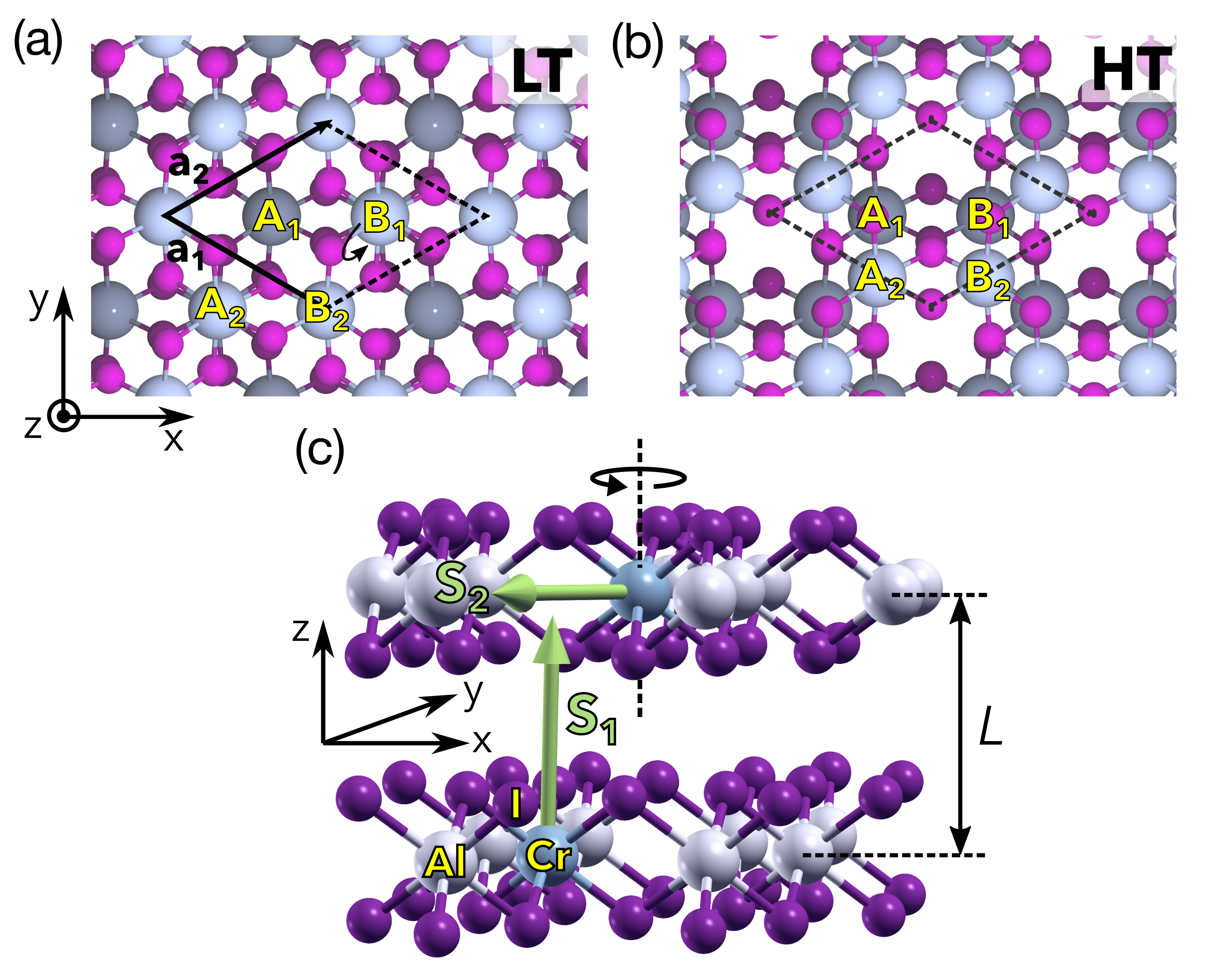
In calculating the interlayer exchange tensors, we follow a two-step computational procedure: in the first step the electron density and the Kohn-Sham wavefunctions are obtained from noncollinear self-consistent field calculations (SCF) without SOC. The directions of spins and on Cr atoms are constrained perpendicular to one another (Fig. 1c) using the penalty functionalMa2015Feb . In the second step the Kohn-Sham wavefunctions from the first step are used, the SOC is included on all the atoms and the sum of the band energies are calculated for different directions of the spin quantization axis. The spin is kept parallel to the spin quantization axis so that it rotates together with it, whereas the direction of is unaffected by this rotation (see Fig. 1c). Given that only the sum of band energies is used, our procedure can be applied to any system provided that the use of the magnetic force theorem is justifiedLiechtenstein1987May ; Solovyev2021Mar ; Soriano2021Oct . The benchmark of our method is provided in Supplementary Information, but here we want to stress that our method can save more than 50% of computational time without affecting the accuracy of the reference four-state method Xiang2012Dec ; Li2021Feb .
II.2 Hamiltonian of two perpendicular spins
Here we derive the model describing the coupling of two perpendicular spins, that is used for mapping the differences between DFT band energies obtained for different directions of the spin quantization axis. In closer detail, we suppose that the two spins belong to different layers, but the model works perfectly fine if spins are from the same layer.
The total energy of such two-spin system is
| (1) |
where is the nonmagnetic contribution, is an exchange tensor that couples spins and , and is the SIA tensor of layer . If the layers are of the same material and magnetic atoms are Wyckoff partners sharing the same site symmetries, we have . Without loss of generality let us choose the coordinate system by fixing along the -axis and placing in the -plane. Now, and so that the spin configuration is completely determined by a single parameter – the angle between the and the -axis. The Eq. 1 turns into
| (2) |
where we introduced the parameters and for convenience and comprises all the terms that are -independent. The important terms for our discussion are the exchange interaction energy and the contribution from the single-ion anisotropy . If we interchange the roles of and the Eq. 2 yields and . If we further change the rotation axis from to we obtain and (and and that we have already). Therefore, by considering the sets of spin configurations that we denote as and , one obtains all the off-diagonal -matrix elements.
In general, the tensor decomposes into the isotropic Heisenberg exchange and the anisotropic DMI (antisymmetric) and KI (symmetric)Li2021Feb ,
| (3) |
By assumption, the spins are perpendicular and the Heisenberg exchange between them vanishes. Thus, the exchange energy contains only the DMI and the KI contributions, . The DMI is usually expressed as the mixed vector product, , which introduces the Dzyaloshinskii vector,
| (4) |
For a system with a well defined symmetry, the direction of can be (at least partially) determined with the help of Moriya rulesMoriya1960Oct . In Supplementary Information we derive the Moriya rules in a form that is more suitable for our purposes.
Within spin configurations, the total variation of the Kitaev energy is . In analogy to DMI, it is convenient to introduce the vector that quantifies the strength of KI by . Note that in general the matrix , unlike , contains the diagonal elements as well that are out of reach of this method as their calculation require the (anti)parallel spin configurations. Therefore, strictly speaking for a given reference frame the parameter quantifies the strength of the off-diagonal part of the Kitaev interaction.
From Eq. 2, we define the SIA constant as , where is the total variation of the SIA energy term for the rotation of spin around a given axis. It can be easily derived that, for a fixed rotation axis, the energy reaches extrema at and its total variation is . If spin rotates around the -axis, the in-plane SIA constant is obtained, whereas if it rotates around the -(or -) axis the fitting gives the out-of-plane SIA constant, . To sum up all being written about this model, if one performs the DFT calculations for and sets of spin configurations, the , , , and are obtained from fitting to Eq. 2. We discuss this below for the cases of two Cr atoms from different layers.
II.3 Interlayer coupling of perpendicular Cr magnetic moments
Bilayer CrI3 is an illustrative example as it reveals a few different scenarios of interlayer exchange coupling and elucidates the important role of the symmetry of local environment around Cr ions. We will refer to Cr ions pair with its surrounding ligands as “the CrIn–InCr cluster” ( is the number of ligands that participate in the exchange path between Cr ions). We consider the nearest and the next-nearest interlayer neighbors in both LT and HT structures. The coordinate system is chosen in a way so that the Cr-Cr bond is along the -axis, while the -axis is perpendicular to the CrI3 plane (see Fig. 2a). For each considered structure, we perform the symmetry analysis to double check whether the calculated off-diagonal -matrix elements comply with the extended Moriya rules exposed in Supplementary Information.
Starting with the LT bilayer, the nearest and the next-nearest interlayer Cr neighbors are modeled by LT1 and LT2 structures (see Fig. 2a-b). In LT1 the Cr-Cr bond displays inversion, threefold rotation axis parallel to the bond, and three vertical mirror planes. Therefore, the symmetry of CrI3–I3Cr cluster in LT1 satisfies three Moriya rules (a,c,e) and consequently the exchange matrix must be diagonal. In complete agreement our calculations give all the zeros at the off-diagonal slots of the exchange matrix ( in Eq. S1).
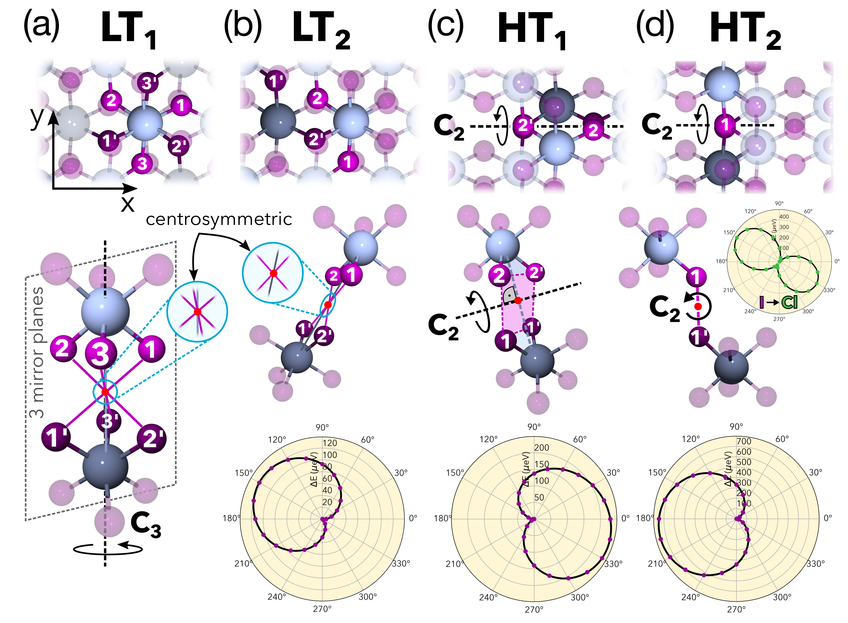
Moving further to next-nearest neighbors, the CrI2–I2Cr cluster in LT2 has only the spatial-inversion symmetry (Moriya rule a) and the exchange matrix is symmetric, thus forbidding the DMI. On the other hand, no symmetry rule forbids the KI and our calculations reveal (Table 1). From this example one can actually see the Kitaev interaction in action: with fixed along the -axis and rotating around it, the energy of the system is changing according to the cardioid pattern which is the direct consequence of the KI (see the polar plot in Fig. 2b).
| structure | ||||||||||
|---|---|---|---|---|---|---|---|---|---|---|
| LT1 (Fig. 2a) | 0 | 0 | 0 | 0 | 0 | 0 | 0 | 0 | 253 | 0 |
| LT2 (Fig. 2b) | 0 | 0 | 0 | 0 | 32 | -14 | 24 | -16 | 240 | 1 |
| HT1 (Fig. 2c) | 175 | 0 | 50 | -168 | 0 | 0 | 0 | 0 | 172 | 19 |
| HT2 (Fig. 2d) | 166 | 0 | -166 | -4 | 25 | -25 | 0 | 0 | 173 | 12 |
| HT (CrCl-ClCr) | 14 | 0 | -14 | 3 | 1 | -1 | 0 | 0 | 163 | 186 |
Moving the discussion to HT stacking, the -axis is a twofold rotational axis for both CrI2–I2Cr in HT1 and CrI–ICr cluster in HT2 structure (see Fig. 2c-d). Given that the Cr-Cr bond is perpendicular to -axis, these two cases fall into the Moriya rule d category. Taking into account the choice of the global coordinate system, the symmetry implies , , and . Although KI is not forbidden by symmetry, our calculations reveal its total absence in HT1 structure and a small of in HT2.
Strikingly, both the nearest and the next-nearest interlayer neighbors in HT structure display considerable DMI in the range of (Table 1). In Moriya’s seminal paper, the DMI is derived from SOC and it is shown that the DM energy is linear in SOCMoriya1960Oct . Given that the SOC on iodine (and not on chromium) gives the major contribution to MAE of monolayer CrI3 Lado2017Jun ; Xu2018Nov ; Kim2020Feb , we assume that it is also responsible for the interlayer DMI in bilayer CrI3. This assumption can be tested through ligand replacement. The SOC constant for valence electrons in solids scales as , where is the atomic number Shanavas2014Oct . Therefore, if iodines are replaced with chlorine, by the rule of thumb the DMI would be reduced by times. This simple estimate works surprisingly well, as we reveal that the is reduced 12 times when the two iodines in HT2 cluster are replaced by chlorine (see Fig. 2d and Table 1). Moreover, this example proves the local character of the interlayer DMI, showing that only the ligands in the vicinity of Cr-Cr pair play a role in mediating this anisotropic interaction. Otherwise, the DMI would not be reduced so drastically even after the ICl replacement in the CrI–ICr cluster because the other iodines are still present in the structure. The dependence of DMI on SOC is further discussed in Subsection II.5.
To the best of our knowledge, the effect of stacking on SIA is not addressed in previous studies of bilayer or bulk CrI3. Most often, it is assumed that the SIA obtained from calculations on the monolayer persists in bilayer and bulk. However, SIA is a local property and is thus sensitive to changes of the spin environment, e.g. by altering the stacking sequence in bilayer. Remarkably, we obtained the increase of 50% in from HT to LT stacking (Table 1). Given that SIA largely contributes to magnetic anisotropy, one must take this change into account when estimating the critical temperature of bilayer or bulk CrI3. Further, we obtained that LT bilayer is isotropic to the in-plane spin rotations () like in the monolayer CrI3Lu2020Sep , but not in HT bilayer where a small in-plane SIA of is induced by stacking. This in-plane SIA is responsible for the distortion of the cardioid that corresponds to the HT1 structure, Fig. 2c. Taking into account all being written in this Section, one should be truly careful in ascribing the monolayer magnetic properties to bilayer and bulk VdW magnets, as the interlayer interactions proved more important than was initially expected.
II.4 Interlayer coupling of perpendicular magnetizations
In this Subsection we move away from the two-spin systems and provide the description of coupling between the fully magnetized layers with perpendicular magnetizations. With fully magnetized layers, we assume that all the spins in the layer point to the same direction. In general, when spins are randomly distributed, the total energy of bilayer CrI3 (that contains spins per layer) is a sum of the nonmagnetic energy, the contributions from the intralayer and interlayer exchange coupling of spins, and SIA contributions at each spin site,
| (5) |
where is the layer index and and are indices numbering the spin sites. The interlayer exchange tensor describes the coupling between the spins and from different layers, whereas the intralayer exchange tensor describes the coupling between spins and from the same layer .
If we assume that all the spins belonging to one layer point to the same direction, i.e. , the Eq. 5 greatly simplifies,
| (6) |
where and are the total and the non-magnetic energy expressed per unit cell. In Eq. 6 the contributions from and sublattices (see Fig. 1a,b) are separated in a sense that describes the interlayer coupling between all the spins at sites with all the spins at sites ( of each). The tensor describes the interaction of a single spin at site with all the other spins from the same layer. If we specify the spins and the Eq. 6 reads
| (7) |
which is the same equation as Eq. 2. The parameters and stemming from and will be used solely for fitting purposes and will not be further discussed, as our focus is on .
We calculated the off-diagonal elements of -matrix for HT bilayer and obtained a weak interlayer KI of . On the other hand, already from the spatial-inversion symmetry of HT bilayer we know that there is no DMI as the () contribution to the Dzyaloshinskii vector exactly cancels that from (). Nevertheless, this does not mean that the interlayer DMI between the sublattices is zero. To inspect this, we modeled the sublattice of the HT structure by replacing the Cr atoms of the sublattice with Al (Fig. 3a) and obtained the Dzyaloshinskii vector with a magnitude of . This is a remarkable result, as the estimated ratio is 80% ( from Ref. Jang2019Mar ), much higher than the 10% threshold which is already considered promising for skyrmionicsKoshibae2014Oct ; Zhang2020Dec ; Xu2020Feb . Compared with the experimental results, the is twice higher than the interlayer DM energy reported for TbFe/Pt/Co multilayers, which is among the strongest interlayer DMI realized in experimentsAvci2021Oct .
II.5 Dependence of DMI/KI on structural transformations and SOC
As shown in Fig. 3b, the magnitude of both the DMI and KI display a fast, exponential-like decrease when the interlayer distance is larger than , consistently with the expected weak interaction between the layers across the VdW gap. At shorter separation, the evolution with suggests a more complicated situation, especially for the KI which displays a non-monotonic behavior.
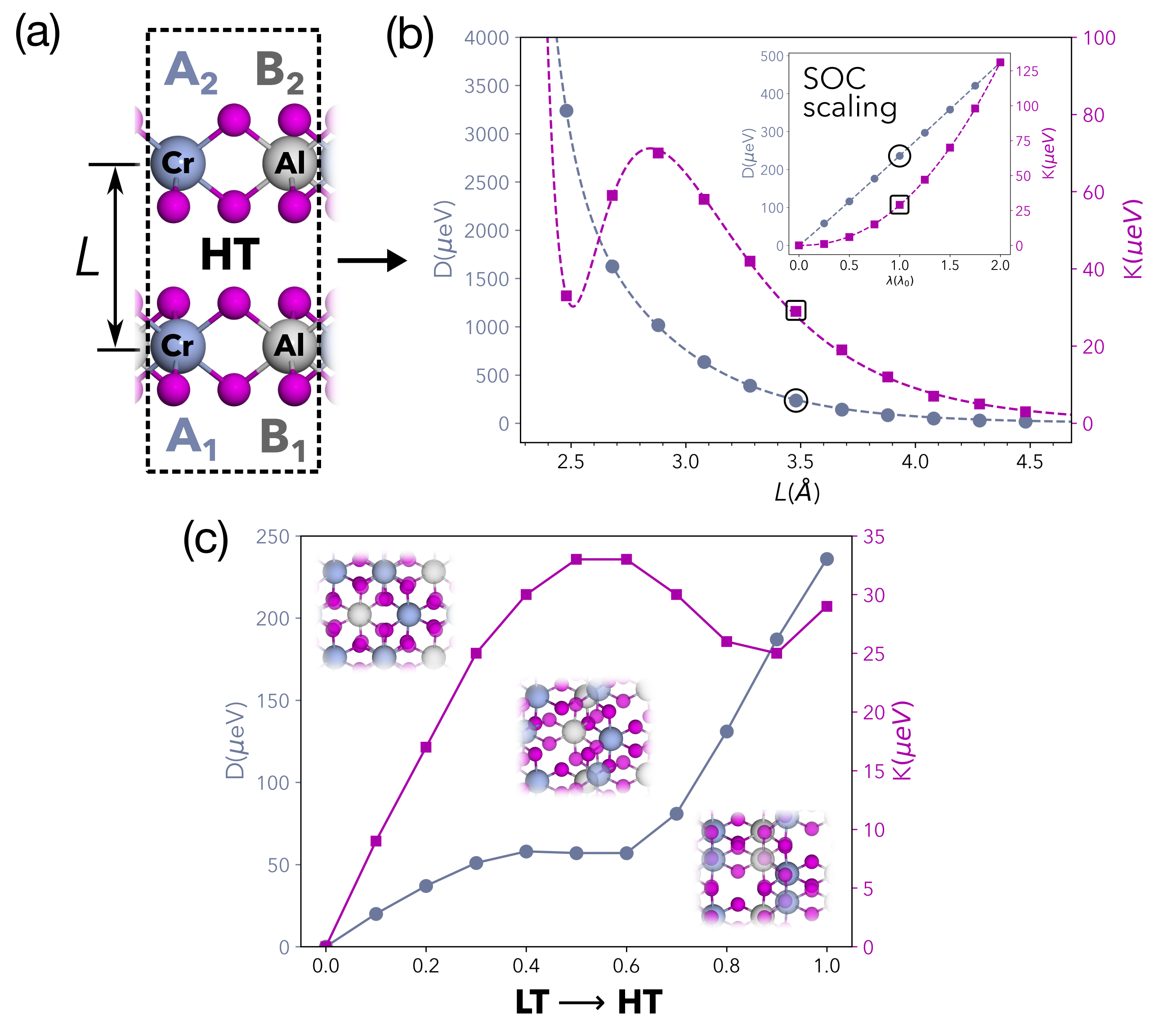
Assuming a superexchange-like mechanism for both interactions, the dependence on the interlayer distance can be rationalized taking into account the possible exchange paths involving different transfer integrals (hopping terms) between Cr and I ions and their expected dependence on the relative bond lengths . One can identify three such hopping terms, corresponding to - direct hopping (), - hopping () and - hopping (), where we adopted the bond-length dependence of Harrisonharrison_book . In perturbation theory, the exchange interaction can be expressed quite generally as a sum of terms each with the form , where is a polynomial function of atomic SOC , charge transfer energy , and on-site Coulomb interaction and the exponent depends on the number of hopping terms involved in the exchange path. For instance, the contribution to the exchange interaction arising from the direct - hopping between Cr atoms scales as . Similarly, a Cr-I-Cr exchange path involving a single ligand I– intermediate state would scale as , while a Cr-I-I-Cr exchange path would also include a - transfer integral, scaling overall as . Neglecting the details of the bond geometries and the angular dependence of each transfer integral and assuming that the dependence on the interlayer distance inherits the same scaling law of hopping terms, one can derive a general functional expression for both and that reads
| (8) |
where stands for or and are fitting parameters effectively including all the complicated dependence on interaction matrix elements. We stress the fact that different exchange paths can give rise to perturbation terms with the same scaling dependence on the interlayer distance, that are effectively regrouped in Eq. 8. As an example, the Cr-I-Cr exchange path shares the same dependence with a process where an electron is transferred from one Cr to the other magnetic atom through both ligands and then transferred back via a direct - process.
Despite the underlying crude approximations, Eq. 8 captures surprisingly well the evolution of both DMI and KI as a function of the overall interlayer distance, as shown in Fig. 3b. Remarkably, the non-monotonic dependence of KI can be quite naturally interpreted as arising from the competition of different super-superexchange processes occurring across the VdW gap. Notwithstanding the phenomenological nature of the fitting parameters, some general trends can be deduced. For both interaction terms, is negative while and are positive: the largest coefficients are those involving - hopping terms, which dominate at short separation, while in the opposite limit the first term – showing a slower decay – prevails. For instance, at the optimal distance Å, one has eV and eV, with the dominant contribution arising from the slow-decaying term: a compression of 18% causes an increase of both interactions by more than 300% and 140%, respectively, but the first two terms in Eq. 8 largely compensate each other and the third term starts to kick in, as meV and meV.
It is worth reminding that the intralayer Kitaev interaction in monolayer CrI3 (not to be confused with as defined in Subsection II.2) has been shown to scale quadratically with ligand iodine SOC, the transition-metal SOC contribution being negligibleXu2018Nov . The superexchange mechanisms leading to anisotropic exchange interactions are therefore different from those discussed in the seminal Moriya’s paperMoriya1960Oct , where it was assumed that the spin of the magnetic atom couples to its own orbital moment. On the other hand, the microscopic mechanisms at play are analogous to those analysed for related transition-metal dihalides, sharing with trihalides similar local bonding environments and strong magnetic anisotropiesamoroso2020spontaneous ; riedl2022 . To shed light on SOC dependence of interlayer anisotropic exchange couplings in bilayer CrI3, we varied the SOC constant from (no SOC) to (double the original value), as shown in the inset of Fig. 3b, and fitted the values to the power function . The fit yielded and (see Fig. 3c), meaning that is a linear function of whereas has nearly quadratic behavior as the intralayer Kitaev interaction. The scaling analysis on both SOC and interlayer distance suggests that superexchange mechanisms are effective in CrI3 bilayer despite the presence of a VdW gap.
To examine the influence of a stacking sequence we gradually translated the upper layer along the lattice vector, starting from the LT and ending with the HT structure (Fig. 3c). The different behavior of and with stacking alteration demonstrates the importance of angles in the Cr-I-I-Cr bonds for hopping processes that are governing the interlayer interaction. Along the inspected direction of translation, reaches it’s maximum of on the halfway between the LT and HT, whereas the maximum of of is in the HT structure. It is interesting to see that for structures that are intermediate between LT and HT the DMI and KI are the same order of magnitude. Note that in order to find the global maximum of and one should inspect all possible directions, which is a demanding computational task that goes out of the scope of the present work.
III Discussion
DFT calculations supported by Hamiltonian modeling reveal strong interlayer DMI in () sublattice of HT bilayer CrI3. At the microscopic scale, DMI in HT bilayer emerges between the nearest and the next-nearest interlayer Cr neighbors due to broken local spatial inversion. However, due to the global C2 symmetry of sublattices, the contributions from and cancel each other resulting in zero net macroscopic DMI. In addition to DMI, there is an order of magnitude weaker interlayer KI that does not vanish due to symmetry. In LT structure there is no DMI as the Cr-Cr pair with their surrounding iodines are centrosymmetric. Despite the DMI in HT structure dies out at the macroscopic scale, the main result of this work is the demonstration of the ability of iodine ligands to efficiently mediate the anisotropic exchange between the magnetic layers. This ability comes from the strong SOC of spatially extended I- orbitals and is impaired if iodine atoms are replaced by other ligands that have weaker SOC. The developed computational procedure offers unprecedented accuracy in calculating the anisotropic exchange interactions. Being quite general, it can be applied in any magnetic material provided that the use of the magnetic force theorem is physically sound. The symmetry analysis and the benchmark with the reference four-state method firmly support the accuracy offered by our method. In addition to the detailed analysis of the anisotropic interlayer exchange, we demonstrated that SIA heavily depends on stacking. Therefore, in estimating the Curie temperature of bilayer or bulk VdW magnet, one should not use the SIA calculated for a monolayer but instead should calculate the SIA for the system of interest.
With all being said, bilayer CrI3 is not an appropriate 2D magnetic system for the experimental demonstration of interlayer DMI. Notwithstanding, we identified all the bricks needed to build one. Instead of attempting to modify the bilayer CrI3, the approach that seems more promising is to build from scratch a new heterostructure by finding an appropriate 2D magnet that can complement a layer of CrI3. Using a different 2D magnet as second layer has a huge advantage in inducing DMI, as one doesn’t need to worry about the spatial-inversion symmetry which is trivially broken by different chemical composition of the two layers. To efficiently mediate the DMI between the magnetic ions, a candidate 2D magnet should have ligands that feature strong SOC. Most importantly, contrary to CrI3 it should show in-plane magnetic anisotropy in order to maximize the product and its MAE should be strong enough to compete with the interlayer Heisenberg exchange that favors the (anti)parallel spin configuration.
Within the CrX3 family of 2D magnets only CrCl3 shows an easy–plane MAELu2020Sep , but the other properties discredit it from potential candidacy. First, its MAE is extremely small and when combined with CrI3 all the chances are that the interlayer Heisenberg exchange will prevail, directing CrCl3 magnetization out of plane. Second, the Cr-I-Cl-Cr interaction path is far less efficient than Cr-I-I-Cr in mediating DMI, due to small SOC on Cl. We further note that due to the lattice constant mismatch between CrI3 and CrCl3 one would need to match structure of CrI3 with structure of CrCl3 to build a CrI3/CrCl3 heterostructure, ending up with a 680 atoms in the supercell. Hence, due to high computational demands, we were not able to check these assumptions, thus leaving the search for a potential candidate for future studies.
IV Methods
DFT calculations are performed using the Vasp codeKresse1996Oct . To describe the effects of electronic exchange and correlation we used the Perdew–Burke–Ernzerhof (PBE) functional PBE . We did not employ and effective Hubbard parameter but we are aware that the choice of may affect the exchange coupling, as it is the case for monolayer CrI3Xu2018Nov . The lattice constant of monolayer CrI3 is obtained from spin-polarized collinear DFT calculations assuming the FM ground state. The interlayer distance is set to , which corresponds to the experimental interlayer distance in bulk HT structure McGuire2015Jan . The bilayer made by stacking two monolayers was not relaxed any further. The lattice vector along the -axis was set to 30Å so that the vacuum between periodic replicas along -axis is 20 Å thick. A cutoff of is imposed onto the plane wave basis set and the total energies are converged to the precision of . The Brillouin zone of the supercell was sampled by -centered -points mesh. The results didn’t change with further increase in -point density owing to semiconducting nature of CrI3. The directions of magnetic moments on Cr atoms were constrained using the approach exposed in Ref.Ma2015Feb . We carefully checked whether the size of the sphere (RWIGS) used for calculating the magnetic moments on Cr atoms and the weight of the penalty functional (LAMBDA) affect the obtained -matrix elements. In the end we used and .
Acknowledgment
The authors acknowledge support from the Italian Ministry for Research and Education through PRIN-2017 projects “TWEET: Towards ferroelectricity in two dimensions” (IT-MIUR Grant No. 2017YCTB59) and “Quantum 2D: Tuning and understanding Quantum phases in 2D materials” (IT-MIUR Grant No. 2017Z8TS5B). SS thanks Marko Milivojević for very useful discussions about the role of spin-orbit coupling in the superexchange interaction.
References
References
- (1) Huang, B. et al. Layer-dependent ferromagnetism in a van der Waals crystal down to the monolayer limit. Nature 546, 270–273 (2017).
- (2) Gong, C. et al. Discovery of intrinsic ferromagnetism in two-dimensional van der Waals crystals. Nature 546, 265–269 (2017).
- (3) Klein, D. R. et al. Probing magnetism in 2D van der Waals crystalline insulators via electron tunneling. Science 360, 1218–1222 (2018).
- (4) Song, T. et al. Giant tunneling magnetoresistance in spin-filter van der Waals heterostructures. Science 360, 1214–1218 (2018).
- (5) Wang, Z. et al. Very large tunneling magnetoresistance in layered magnetic semiconductor CrI3. Nat. Commun. 9, 1–8 (2018).
- (6) Gibertini, M., Koperski, M., Morpurgo, A. F. & Novoselov, K. S. Magnetic 2D materials and heterostructures. Nat. Nanotechnol. 14, 408–419 (2019).
- (7) Soriano, D., Katsnelson, M. I. & Fernández-Rossier, J. Magnetic Two-Dimensional Chromium Trihalides: A Theoretical Perspective. Nano Lett. 20, 6225–6234 (2020).
- (8) Huang, B. et al. Electrical control of 2D magnetism in bilayer CrI3. Nat. Nanotechnol. 13, 544–548 (2018).
- (9) Morell, E. S., León, A., Miwa, R. H. & Vargas, P. Control of magnetism in bilayer CrI3 by an external electric field. 2D Mater. 6, 025020 (2019).
- (10) Jiang, P. et al. Stacking tunable interlayer magnetism in bilayer . Phys. Rev. B 99, 144401 (2019).
- (11) Song, T. et al. Switching 2D magnetic states via pressure tuning of layer stacking. Nat. Mater. 18, 1298–1302 (2019).
- (12) Xu, Y. et al. Coexisting ferromagnetic–antiferromagnetic state in twisted bilayer CrI3. Nat. Nanotechnol. 17, 143–147 (2022).
- (13) Dolui, K. et al. Proximity Spin–Orbit Torque on a Two-Dimensional Magnet within van der Waals Heterostructure: Current-Driven Antiferromagnet-to-Ferromagnet Reversible Nonequilibrium Phase Transition in Bilayer CrI3. Nano Lett. (2020).
- (14) Zhang, Y. et al. Switchable magnetic bulk photovoltaic effect in the two-dimensional magnet CrI3. Nat. Commun. 10, 1–7 (2019).
- (15) Soriano, D. & Katsnelson, M. I. Magnetic polaron and antiferromagnetic-ferromagnetic transition in doped bilayer . Phys. Rev. B 101, 041402 (2020).
- (16) Lei, C. et al. Magnetoelectric Response of Antiferromagnetic CrI3 Bilayers. Nano Lett. 21, 1948–1954 (2021).
- (17) Lado, J. L. & Fernández-Rossier, J. On the origin of magnetic anisotropy in two dimensional CrI3. 2D Mater. 4, 035002 (2017).
- (18) Besbes, O., Nikolaev, S., Meskini, N. & Solovyev, I. Microscopic origin of ferromagnetism in the trihalides and . Phys. Rev. B 99, 104432 (2019).
- (19) Kashin, I. V., Mazurenko, V. V., Katsnelson, M. I. & Rudenko, A. N. Orbitally-resolved ferromagnetism of monolayer CrI3. 2D Mater. 7, 025036 (2020).
- (20) Mermin, N. Crystalline Order in Two Dimensions. Phys.Rev. 176, 250–254 (1968).
- (21) Xu, C., Feng, J., Xiang, H. & Bellaiche, L. Interplay between Kitaev interaction and single ion anisotropy in ferromagnetic CrI3 and CrGeTe3 monolayers. npj Comput. Mater. 4, 1–6 (2018).
- (22) Moriya, T. Anisotropic Superexchange Interaction and Weak Ferromagnetism. Phys. Rev. 120, 91–98 (1960).
- (23) Evans, R. F. L., Rózsa, L., Jenkins, S. & Atxitia, U. Temperature scaling of two-ion anisotropy in pure and mixed anisotropy systems. Phys. Rev. B 102, 020412 (2020).
- (24) Webster, L. & Yan, J.-A. Strain-tunable magnetic anisotropy in monolayer , , and . Phys. Rev. B 98, 144411 (2018).
- (25) Lu, X., Fei, R. & Yang, L. Curie temperature of emerging two-dimensional magnetic structures. Phys. Rev. B 100, 205409 (2019).
- (26) Xue, F., Hou, Y., Wang, Z. & Wu, R. Two-dimensional ferromagnetic van der Waals monolayer with enhanced anisotropy and Curie temperature. Phys. Rev. B 100, 224429 (2019).
- (27) Lu, X., Fei, R., Zhu, L. & Yang, L. Meron-like topological spin defects in monolayer CrCl3. Nat. Commun. 11, 1–8 (2020).
- (28) Jaeschke-Ubiergo, R., Suárez Morell, E. & Nunez, A. S. Theory of magnetism in the van der Waals magnet . Phys. Rev. B 103, 174410 (2021).
- (29) McGuire, M. A., Dixit, H., Cooper, V. R. & Sales, B. C. Coupling of Crystal Structure and Magnetism in the Layered, Ferromagnetic Insulator CrI3. Chem. Mater. 27, 612–620 (2015).
- (30) Sivadas, N., Okamoto, S., Xu, X., Fennie, Craig. J. & Xiao, D. Stacking-Dependent Magnetism in Bilayer CrI3. Nano Lett. 18, 7658–7664 (2018).
- (31) Jang, S. W., Jeong, M. Y., Yoon, H., Ryee, S. & Han, M. J. Microscopic understanding of magnetic interactions in bilayer . Phys. Rev. Mater. 3, 031001 (2019).
- (32) Soriano, D., Cardoso, C. & Fernández-Rossier, J. Interplay between interlayer exchange and stacking in CrI3 bilayers. Solid State Commun. 299, 113662 (2019).
- (33) Kong, X., Yoon, H., Han, M. J. & Liang, L. Switching interlayer magnetic order in bilayer CrI3 by stacking reversal. Nanoscale 13, 16172–16181 (2021).
- (34) Li, T. et al. Pressure-controlled interlayer magnetism in atomically thin CrI3. Nat. Mater. 18, 1303–1308 (2019).
- (35) Ke, L. & Katsnelson, M. I. Electron correlation effects on exchange interactions and spin excitations in 2D van der Waals materials. npj Comput. Mater. 7, 1–8 (2021).
- (36) Song, K. W. & Fal’ko, V. I. Superexchange and spin-orbit coupling in monolayer and bilayer chromium trihalides. Phys. Rev. B 106, 245111 (2022).
- (37) Akram, M. et al. Moiré Skyrmions and Chiral Magnetic Phases in Twisted CrX3 (X = I, Br, and Cl) Bilayers. Nano Lett. 21, 6633–6639 (2021).
- (38) Yang, B., Li, Y., Xiang, H., Lin, H. & Huang, B. Moiré magnetic exchange interactions in twisted magnets. Nat. Comput. Sci. 3, 314–320 (2023).
- (39) Vedmedenko, E. Y., Riego, P., Arregi, J. A. & Berger, A. Interlayer Dzyaloshinskii-Moriya Interactions. Phys. Rev. Lett. 122, 257202 (2019).
- (40) Avci, C. O., Lambert, C.-H., Sala, G. & Gambardella, P. Chiral Coupling between Magnetic Layers with Orthogonal Magnetization. Phys. Rev. Lett. 127, 167202 (2021).
- (41) Xiang, H., Lee, C., Koo, H.-J., Gong, X. & Whangbo, M.-H. Magnetic properties and energy-mapping analysis. Dalton Trans. 42, 823–853 (2012).
- (42) Ma, P.-W. & Dudarev, S. L. Constrained density functional for noncollinear magnetism. Phys. Rev. B 91, 054420 (2015).
- (43) Liechtenstein, A. I., Katsnelson, M. I., Antropov, V. P. & Gubanov, V. A. Local spin density functional approach to the theory of exchange interactions in ferromagnetic metals and alloys. J. Magn. Magn. Mater. 67, 65–74 (1987).
- (44) Solovyev, I. V. Exchange interactions and magnetic force theorem. Phys. Rev. B 103, 104428 (2021).
- (45) Soriano, D., Rudenko, A. N., Katsnelson, M. I. & Rösner, M. Environmental screening and ligand-field effects to magnetism in CrI3 monolayer. npj Comput. Mater. 7, 1–10 (2021).
- (46) Li, X. et al. Spin Hamiltonians in Magnets: Theories and Computations. Molecules 26, 803 (2021).
- (47) Kim, J. et al. Exploitable Magnetic Anisotropy of the Two-Dimensional Magnet CrI3. Nano Lett. 20, 929–935 (2020).
- (48) Shanavas, K. V., Popović, Z. S. & Satpathy, S. Theoretical model for Rashba spin-orbit interaction in electrons. Phys. Rev. B 90, 165108 (2014).
- (49) Koshibae, W. & Nagaosa, N. Creation of skyrmions and antiskyrmions by local heating. Nat. Commun. 5, 1–11 (2014).
- (50) Zhang, Y. et al. Emergence of skyrmionium in a two-dimensional Janus monolayer. Phys. Rev. B 102, 241107 (2020).
- (51) Xu, C. et al. Topological spin texture in Janus monolayers of the chromium trihalides Cr(I, . Phys. Rev. B 101, 060404 (2020).
- (52) Harrison, W. A. Electronic Structure and the Properties of Solids (Dover Publications, N. Y., 1989).
- (53) Amoroso, D., Barone, P. & Picozzi, S. Spontaneous skyrmionic lattice from anisotropic symmetric exchange in a ni-halide monolayer. Nat. Commun. 11, 5784 (2020).
- (54) Riedl, K. et al. Microscopic origin of magnetism in monolayer transition metal dihalides. Phys. Rev. B 106, 035156 (2022).
- (55) Kresse, G. & Furthmüller, J. Efficient iterative schemes for ab initio total-energy calculations using a plane-wave basis set. Phys. Rev. B 54, 11169–11186 (1996).
- (56) Perdew, J., Burke, K. & Ernzerhof, M. Generalized gradient approximation made simple. Phys. Rev. Lett. 77, 3865–3868 (1996).