Experimental Assessment of Misalignment Effects in Terahertz Communications
Abstract
Terahertz (THz) frequencies are important for next generation wireless systems due to the advantages in terms of large available bandwidths. On the other hand, the limited range due to high attenuation in these frequencies can be overcome via densely installed heterogeneous networks also utilizing UAVs in a three-dimensional hyperspace. Yet, THz communications rely on precise beam alignment, if not handled properly results in low signal strength at the receiver which impacts THz signals more than conventional ones. This work focuses on the importance of precise alignment in THz communication systems and the significant effect of proper alignment is validated through comprehensive measurements conducted through a state-of-the-art measurement setup, which enables accurate data collection between 240 GHz to 300 GHz at varying angles and distances in an anechoic chamber eliminating reflections. By analyzing the channel frequency and impulse responses of these extensive and particular measurements, this study provides the first quantifiable results in terms of measuring the effects of beam misalignment in THz frequencies.
Index Terms:
Terahertz communications, unmanned aerial vehicles (UAVs), channel frequency response, channel impulse response.I Introduction
While the need for high data rates is still on the agenda, the 6G vision has highlighted various key value indicators (KVIs) such as global coverage, service availability, sustainability, and reliability. When we set out with the \sayconnection in anywhere, anytime, any device motto, there is no doubt that aerial systems will be the most prominent candidate to bring access to urban, semi-urban, and remote rural areas. Adding aerial base stations for improving the quality of service (QoS) and boosting the coverage, reliability and capacity of wireless networks has been suggested in the academy for a while [1, 2, 3]. In addition to bringing fast deployment features to non-terrestrial networks (NTNs), unmanned aerial vehicles (UAVs) also act as a bridge between terrestrial networks (TNs) and other non-terrestrial network elements such as satellites and high altitude platforms (HAPs).
Terahertz (THz) wireless systems are expected to be a vital enabler for 6G in tandem with TNs and NTNs because of their large contiguous bandwidth [4] which allows them to keep pace with the surge in wireless data volume and the increasing amount of traffic as new nodes are added to the network. Likewise, considering the fact that THz bands are not allocated yet for specific active services around the globe, there is an enormous potential to meet the need for the desired communication traffic. Hence the orchestration of NTNs and TNs with the THz communication is apparent towards 6G[5].
Along with their benefits, THz frequencies also come with high attenuation due to molecular absorption and spreading loss [6], which limits the communication range significantly. Thus, innovative densely deployable THz communication systems are required to cope with this issue. This is where UAVs come into play as a solution especially to provide instant high-capacity communication link in crowded environments or to support high-capacity data traffic between different TN and NTN nodes [7]. Moreover, along with their cost-effectiveness and instant 3D deployment capabilities which allow maintaining line-of-sight (LoS) condition for the communication links, UAVs also provide flexibility to the network nodes. Thus, UAVs are expected to pave radically the way for assisting THz communications. UAVs and THz are strong collaborators by nature and this mutually constructive relationship, in turn, can unlock new opportunities and innovative services[8].
While THz-integrated UAVs presents promising prospects they also bring new challenges to the field. Although the utilization of directional beamforming unified with directional antennas can provide higher antenna gains to reduce the high transmission loss in the THz frequency range, these systems are prone to pointing errors due to small beamwidths. Moreover, wind or sudden complex movements can cause uncontrollable tilts or rotations in UAV operations, leading to beam misalignment and an inevitable decrease in signal-to-noise ratio (SNR). Accordingly, UAV-assisted THz communication requires accurate beam alignment mechanisms and algorithms. As we move towards the development of 6G networks and the realization of THz communication systems, it is crucial to conduct a comprehensive investigation of misalignment scenarios. This involves analyzing and modeling the potential effects of the misalignment on specific applications.
I-A Related Works
The antenna misalignment effects on THz communication systems have been investigated across various environments and frequency ranges, but mostly by simulations [9, 10, 11, 12]. In particular, [9] and [10] examined the effects of antenna misalignment at 300 GHz in a simulated office setup by considering practical propagation conditions. In [11], the performance of a multicarrier THz wireless system is evaluated under the fading condition caused by misalignment. The effects of pointing error impairments under random fog conditions are examined in [12].
On the other hand, measurement based impact of misalignment has been analysed in [13, 14]. The authors in [13] carried out measurements to analyze the impact of the distance and single degree of misalignment on the path loss in the THz communication system and several important statistical parameters for line–of–sight (LOS) channels are measured. The performance of the experimental THz communication systems has been examined in case of antenna misalignment at 100, 300, 400 and 500 GHz by utilizing proper horn antennas in the [14]. A significant decrease trend was indicated in the received power with misalignment due to the divergence of the beams particularly with an increase in separation distance. Most importantly, the authors in [15] have designed a drone-based measurement setup to investigate the effects of mobility uncertainties on mmWave/THz-band communications between flying drones. The authors showed that the mobility of the UAVs when they are in movement causes significant performance degradation and link outages while propeller rotation and engine operations of the UAVs cause far less performance degradation.
I-B Contributions
In order to fully maximize the potential of THz communication systems, a deep understanding of their performance in practical conditions is required. As the realization of the UAV-assisted THz communication becomes increasingly prevalent, the effect of misalignment becomes a more prominent concern. While prior studies have explored the impact of distance and antenna misalignment to some extent on THz communication but more comprehensive approaches ought to address this issue. To achieve this, it is essential to gather application-specific measurements and conduct an in-depth analysis of their impact on channel frequency and impulse response. In the light of these motivations, our contributions are listed as follows:
-
•
Undertaking precise controlled THz misalignment experiments is a formidable task that requires extensive expertise and experience. In order to unravel the intricacies involved, a groundbreaking measurement system has been devised to capture precise measurements under varying misalignment scenarios and at different distances. Moreover, this study strives to illuminate future research endeavours by providing a comprehensive elucidation of the measurement campaign and sharing invaluable insights derived from a multidisciplinary approach.
-
•
Also, recognizing the significance of high bandwidths in practical THz communication systems, this study stands apart from the majority of existing literature on THz measurements. Rather than focusing solely on a specific frequency range, measurements were conducted using a single scan method, encompassing the 60 GHz band and spanning from 240 GHz to 300 GHz.
-
•
The measurements were analyzed in terms of the channel frequency and impulse responses to gain insights into the joint effect of the distance and misalignment.
I-C Organization
The remainder of this paper is organized as follows: in Section II, the signal model is introduced, providing a foundational understanding of the system. Subsequently, the measurement campaign is explained, outlining the approach and methodology employed. The obtained measurement results are presented in Section III, showcasing valuable findings and insights. Finally, the conclusion and future directions are discussed in Section IV, summarizing the key outcomes and presenting potential avenues for further research.
II Signal Model and System Overview
In this study, the effect of misalignment for THz channels is investigated in the anechoic chamber. The traditional linear, time-invariant channel model approach is used to reduce complexity in the analysis.
II-A Signal Model
The received signal at the passband can be expressed as
| (1) |
where denotes the carrier frequency. Also, and are the in-phase and quadrature components of the received signal, respectively. The received signal can be modeled as a superposition of multipath signals with different delays and complex gains. So, the channel at the baseband can be represented as
| (2) |
where , , and represent the number of multipath components, channel complex gain, and delay for the -th path, respectively. As we have mentioned before, measurements have been carried out in a fully isolated anechoic chamber, so we can assume there is only LoS signal transmission. Thus, LoS channels can be derived for (2) as
| (3) |
where , , and denote the LoS path complex gain, phase of the signal, and propagation delay, respectively. Also, is the distance between the transmitter and receiver, and is the speed of the light. It is crucial to acknowledge that when using directional antennas, which is a common practice in THz communication, the effects of antenna misalignment, frequency-dependent loss, and frequency dispersion index can all be accounted for by the term .
In existing literature, the stochastic characterization of multipath components in a static environment is commonly regarded as a combination of specular and diffused components, forming a superposition [16].
| (4a) | ||||
| (4b) |
| (4c) |
where the term represents the magnitude of the specular component, while denotes the angle of arrival (AoA) and represents the phase of the specular component. Similarly, corresponds to the magnitude of the diffused component, signifies the number of diffused waves, represents the amplitude of the incoming waves, denotes the AoA, and is the phase of the incoming waves forming the diffused component, respectively. It is commonly assumed, without loss of generality, that both and can be considered as unity under ideal conditions.
The LoS scenario stands out as a special case in wireless propagation, exhibiting inherent characteristics in both large-scale and small-scale fading mechanisms. To guarantee LoS transmission, it is crucial to implement a fully isolated measurement setup within an anechoic chamber, incorporating absorbers. This setup effectively limits the losses introduced by the propagation channel to factors such as distance-dependent path loss, potential antenna misalignments, equipment imperfections, and non-ideal behaviors that may arise when operating in proximity to or above ideal conditions.
In this model, the losses are contingent upon both the distance and misalignment between the transmitter and receiver. When taking into account the distance and angular losses associated with a directional antenna having a maximum gain direction angle , the loss can be expressed in decibels dB as follows:
| (5) |
is the distance between the extender modules. represents the normalized angular gain pattern of an antenna and is the angle between the extender modules.
The angular gain function in linear scale can be approximated as [17]
| (6) |
where is a parameter linked to both the maximum gain direction angle and the beamwidth of the directional antenna. The antenna beamwidth can be defined as twice the angular value at which the measured power in the maximum gain direction decreases by half.
II-B Measurement Setup
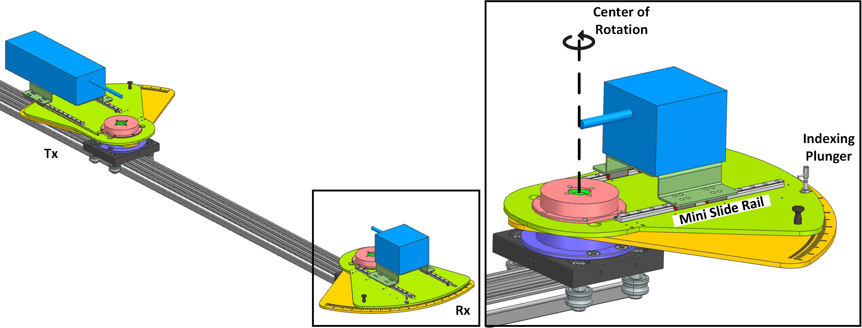
One of the most critical factors to be considered in misalignment experiments is ensuring the repeatability of the measurements. Especially when the focus is on THz frequencies various factors must be considered where even the slightest change can significantly impact the results. Foremost, it is necessary to ensure the accuracy of the position, which is the reference in examining the misalignment effect. In addition to the position, periodically verify the alignment of other angles as well. Secondly, the antenna must be in the center of rotation to keep the distance constant during the experiments. In order to ensure sustainability in measurements, the movable rotation platform should be arranged so that the calibration is renewed at regular intervals without removing the extenders. Such a process that starts from designing the measurement setup that serves a particular purpose and reaches the results verified by repeated measurements obliges carrying out a multi-disciplinary effort. Misalignment is controlled by rotating the receiver according to the angle scale. Thanks to the mini slide rail, when the calibration is needed the extenders are brought closer to each other without being removed from the setup, while the indexing plunger prevents unwanted angle changes. With this measurement setup, besides misalignment, distance-dependent measurement can also be taken since the rotation platforms are movable. Thirdly, it is crucial to ensure effective management of cables to avoid signal deterioration and interference. It is recommended to utilize high-quality cables that have suitable shielding to minimize signal losses and maintain a stable transmission. For this study, Minicircuit brand cables with low loss characteristics are preferred, particularly when operating at high frequencies. Fourthly, it is of utmost importance to perform frequent calibration of the measurement equipment, which includes antennas and receivers, in order to uphold precision. This process entails comparing the measured signals to established reference standards or calibrated sources. Regular recalibration is necessary to compensate for any alterations or fluctuations in the equipment’s performance. Fifthly, it is vital to exercise control over the experimental environment to reduce the impact of external factors on the measurements. It is important to carefully manage factors like temperature, humidity, and electromagnetic interference. Implementing shielding measures to safeguard the measurements from external electromagnetic radiation sources is crucial in ensuring precise and accurate measurements. By adhering to these design guidelines, a robust measurement setup can be created that actively minimizes the impact of external factors, resulting in accurate and reliable measurements.
II-B1 Description of Measurement Setup
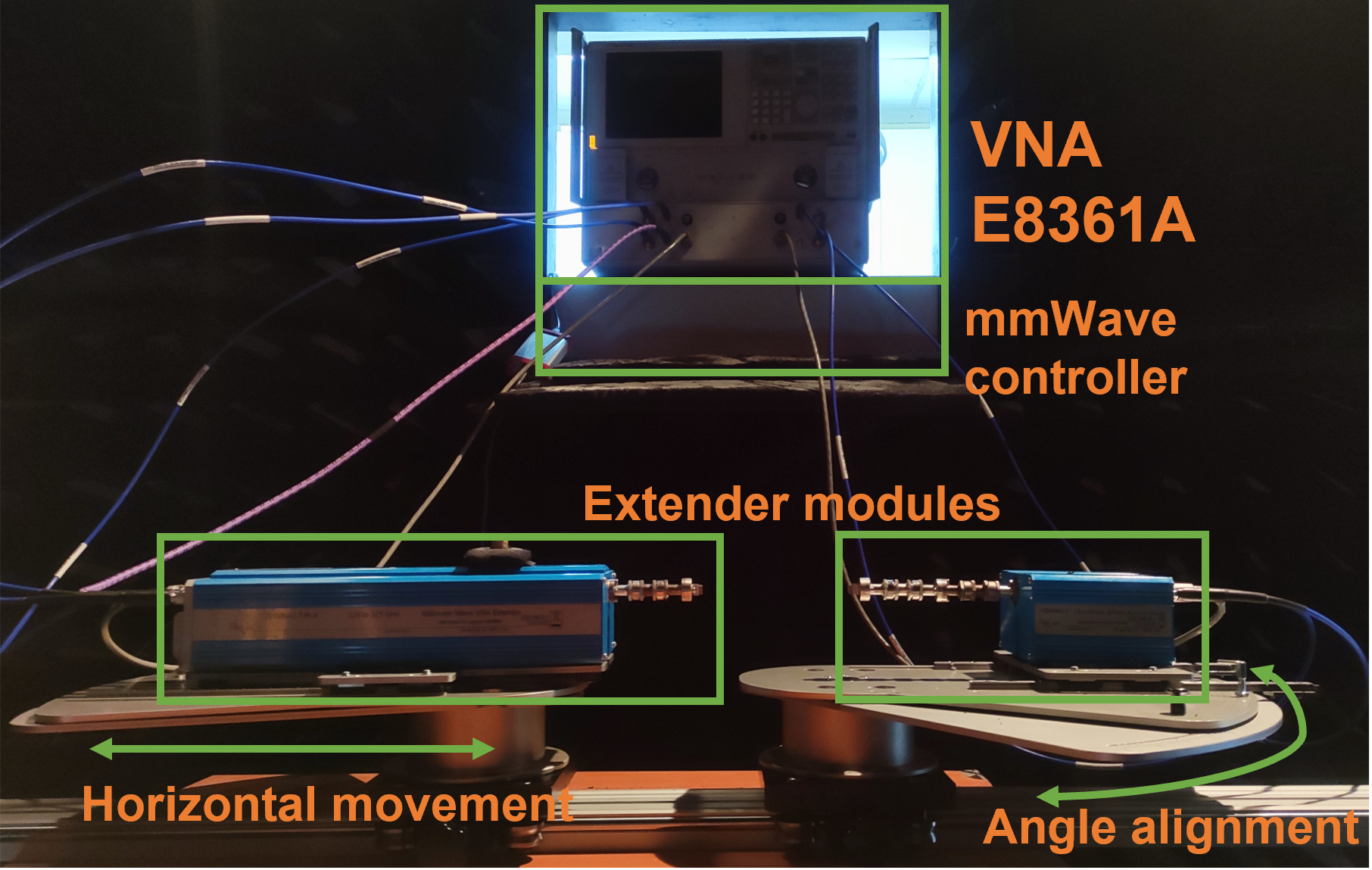
Our THz experimental setup is shown in Fig. 2 which is constructed in the MİLTAL at the TÜBİTAK. The measurement setup consists of four main hardware parts and mechanical parts. Hardware parts of the system consist of Agilent vector network analyzer (VNA) E8361A, Oleson Microwave Labs (OML) V03VNA2-T and V03VNA2–T/R–A millimeter wave extender modules and N5260A extender controller.
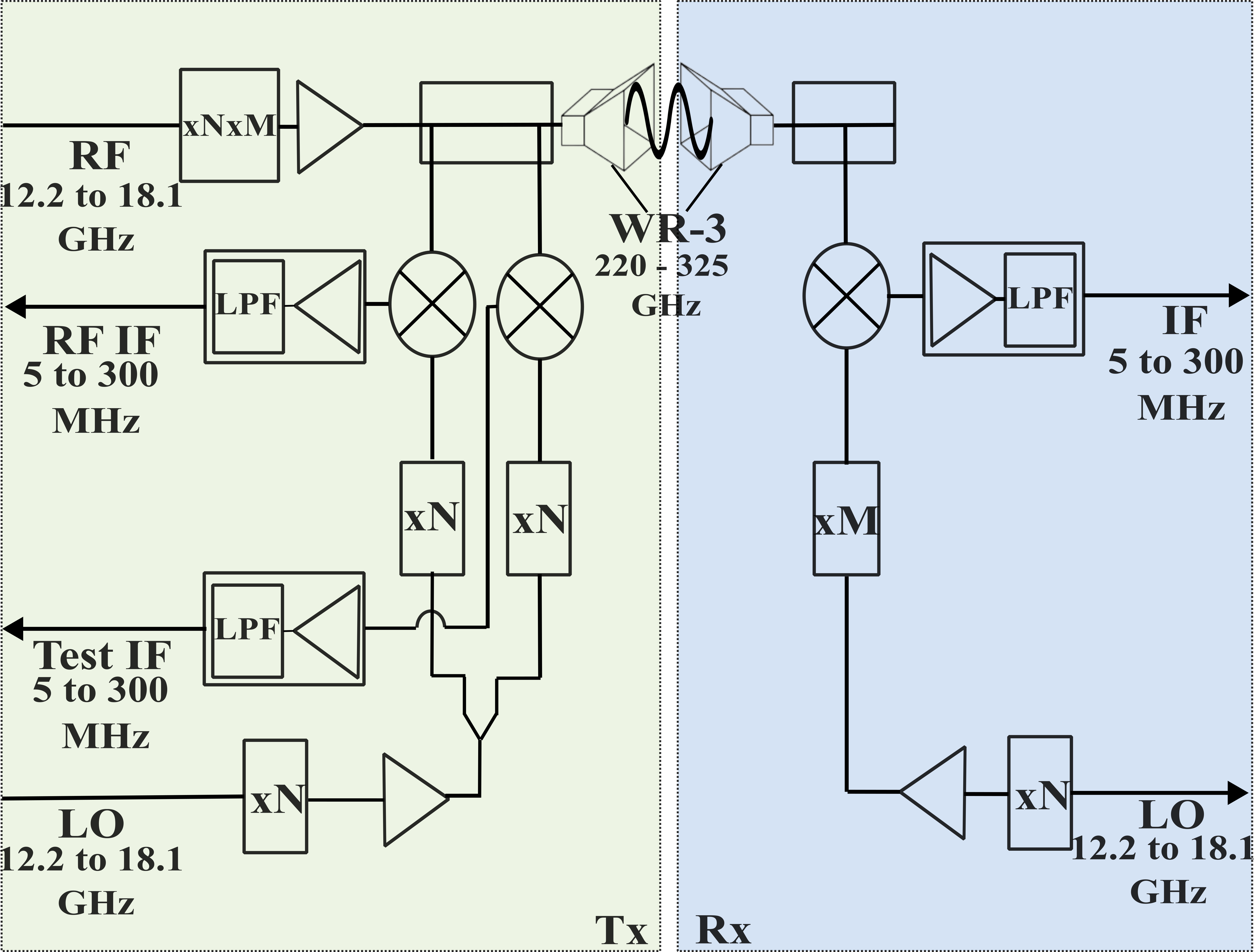
To enable the analysis of misalignment effects on the THz frequency range, extender modules are coupled with the VNA which is limited to an operational frequency of 67 GHz. The V03VNA2–T/R–A drives up the RF signal within the 12.2 GHz and 18.1 GHz range by a factor of 18 and expands the frequency of the transmission signals allowing VNA to analyze signals between 220 GHz and 325 GHz. Prior to transmission, the VNA acquires test intermediate frequency (IF) and reference IF signals through downconversion mixers. Following signal reception after passing through the channel, it undergoes downconversion at V03VNA2-T which results in a test IF signal that is fed back to the VNA for further analysis. The extender modules have been driven by an extended band WR-10 multiplier chain with a WR-03 waveguide output interface. The WR-03 waveguide output power of the V03VNA2-T/R-A is around -23 dBm. Also, the magnitude and phase stability of the extenders is 0.4dB and 8∘, respectively. Because of the narrow beamwidth at high frequencies, the alignment between the transmitter and receiver needs to be very precise. So, the extender modules have been installed in a mechanical system as mentioned in Section II-B where we can precisely change the distance and angles between the modules.
| Description | Value |
|---|---|
| Operating frequency | 240GHz - 300GHz |
| Bandwidth | 60GHz |
| Measurement frequency points | 4096 |
| IF bandwidth | 100Hz |
| Spectral resolution | 14.648MHz |
| Antenna misalignment | and |
| Distance (cm) | 20:10:100cm |
II-B2 Measurement Methodology
In this study, the operating frequency range is set to 240 GHz to 300 GHz because of the magnitude and phase stability of the extender modules in this range. To ensure accuracy, the spectral resolution of each measurement is set to be 14.648 MHz, which corresponds to 4096 frequency points with an IF bandwidth of 100 Hz. To ensure accurate measurements, it is necessary to calibrate electronic devices and cables together. Prior to the measurements, calibration has been done by connecting the waveguide ports of the transmitter and receiver modules end-to-end to retrieve any unwanted effects caused by the electronics. In order to comprehensively investigate the impact of antenna misalignment on received power in the THz wireless channel, a series of measurements were conducted using a sliding rail and rotation platform. These platforms enabled horizontal angle adjustments with a precision of at each distance setting, allowing for a comprehensive investigation of the influence of antenna misalignment with distance.
In order to facilitate analysis and improve the reliability of data by minimizing the number of unknown variables, this study specifically evaluated changes in only the horizontal angle. By limiting the focus to horizontal angle changes, the study was able to produce more accurate and dependable findings. The measurements were obtained as parameters and stored as complex numbers in Agilent VNA E8361A. The parameters of the measurements are presented in detail in Table I.
| 0∘ | 5∘ | 10∘ | 15∘ | 20∘ | 25∘ | 30∘ | |
|---|---|---|---|---|---|---|---|
| 20 cm | -23.77 | -25.02 | -28.19 | -32.48 | -37.79 | -43.13 | -49.29 |
| 30 cm | -25.86 | -27.35 | -30.95 | -35.78 | -41.71 | -47.17 | -53.70 |
| 40 cm | -28.42 | -30.07 | -34.02 | -39.52 | -46.24 | -52.90 | -56.92 |
| 50 cm | -29.66 | -31.38 | -35.40 | -40.74 | -47.07 | -53.25 | -60.85 |
| 60 cm | -31.55 | -33.21 | -37.16 | -42.56 | -49.05 | -54.82 | -62.07 |
| 70 cm | -32.92 | -35.32 | -39.82 | -45.93 | -52.73 | -55.68 | -63.20 |
| 80 cm | -34.71 | -37.92 | -42.03 | -46.13 | -50.92 | -56.15 | -60.51 |
| 90 cm | -35.11 | -36.84 | -40.76 | -46.27 | -52.59 | -59.08 | -66.16 |
| 100 cm | -35.98 | -39.92 | -43.17 | -49.14 | -52.67 | -57.57 | -63.02 |
III Measurement Results
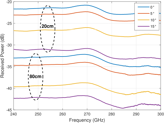
In this section, the joint impact of the antenna misalignment and the distance dependent path loss is presented by illustrating the channel frequency response and impulse response of the measurements. The channel frequency responses for 0,3,5,10 and 15-degree antenna misalignment at 20 cm and 80 cm is shown in Fig. 5. If only the distance between the transmitter and receiver is taken into account, the received power experiences a change of approximately 12 dB when the separation is increased from 20 cm to 80 cm. The 15-degree horizontal angle change from the reference point at 20 cm causes the 8 dB reduction of the received power.
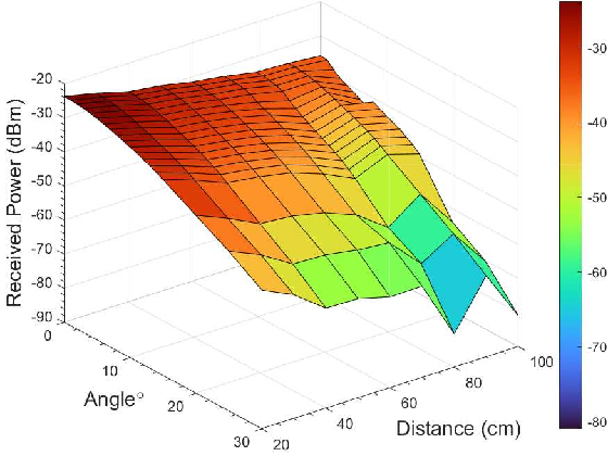
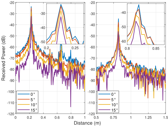
For example, the received power difference is around 12 dB without antenna misalignment for 20 cm and 80 cm. In case of antenna misalignment, loss of the received power can reach up to 8 dB. In addition, Fig. 6 shows that time domain analysis by taking inverse Fourier Transform of the measurement data. In this figure, it is seen that there is a decrease in received power due to antenna misalignment. So, antenna misalignment considerably impacts received signal power because THz antennas have a narrow beam width. Furthermore, Fig. 4 illustrates the channel impulse response with the combined distance and antenna misalignment measurements. It is plotted using the max value of the channel impulse response for every distance and angle measurements pairs. In addition, the direct numerical value equivalents of these measurement pairs are given in the Table II.
In order to better understand the importance of the effect of antenna misalignment on received power, we can analyze the numerical data in Table 2. For example, by increasing the distance between the transmitter and the receiver from 20 cm to 80 cm, the loss in received power is almost equal to the loss due to 10-degree antenna misalignment at a fixed 80 cm distance, and this loss is approximately 9 dB.
Antenna misalignment is an indispensable concern for THz communication systems in UAVs, as it has a direct impact on the received power. The distance between the transmitter and the receiver plays a crucial role in path loss, which inevitably results in a decline in the received power. In addition, when the transmitter and receiver antennas are misaligned, the issue of power loss is exacerbated, causing a further decrease in the received power. In this context, the development of fast and robust beamforming and beam tracking algorithms is imperative for UAVs equipped with THz communication systems. The compensation for misalignment due to several reasons is imperative to maintain the desired level of received power, thus ensuring reliable communication in UAVs operating at THz frequencies.
IV Conclusion and Future Directions
THz communication systems hold promise as a solution for addressing the high data rate demands and increasing number of wireless devices, and UAVs have been featured to enable ubiquitous access to the sublime potential of these frequencies. This study initiates a discussion about antenna misalignment in UAV-assisted THz communication which will be one of the most critical challenges in the practical implementation step. Experiments performed with fine-tuned measurement setup examine the effect of misalignment and distance on the received power between 240 GHz and 300 GHz. Results have shown that even minor deviations in the alignment have a significant impact on SNR. In order to provide direction for future research, we have outlined the essential factors that need to be taken into account when conducting a controlled misalignment experiment. When transceiver technology advances and UAV-mounted THz campaigns become feasible, experiments should be conducted in a real-world setting.
Acknowledgment
We thank to StorAIge project that has received funding from the KDT Joint Undertaking (JU) under Grant Agreement No. . The JU receives support from the European Union’s Horizon 2020 research and innovation programme in France, Belgium, Czech Republic, Germany, Italy, Sweden, Switzerland, Türkiye, and National Authority TÜBİTAK with project ID .
References
- [1] M. Mozaffari, W. Saad, M. Bennis, and M. Debbah, “Drone small cells in the clouds: Design, deployment and performance analysis,” in 2015 IEEE Global Communications Conference (GLOBECOM), 2015, pp. 1–6.
- [2] M. J. Sobouti, A. H. Mohajerzadeh, S. A. H. Seno, and H. Yanikomeroglu, “Managing sets of flying base stations using energy efficient 3D trajectory planning in cellular networks,” IEEE Sensors Journal, 2023.
- [3] M. Giordani, M. Polese, M. Mezzavilla, S. Rangan, and M. Zorzi, “Toward 6G networks: Use cases and technologies,” IEEE Communications Magazine, vol. 58, no. 3, pp. 55–61, 2020.
- [4] A.-A. A. Boulogeorgos, A. Alexiou, T. Merkle, C. Schubert, R. Elschner, A. Katsiotis, P. Stavrianos, D. Kritharidis, P.-K. Chartsias, J. Kokkoniemi et al., “Terahertz technologies to deliver optical network quality of experience in wireless systems beyond 5G,” IEEE Communications Magazine, vol. 56, no. 6, pp. 144–151, 2018.
- [5] K. Tekbiyik, A. R. Ekti, G. K. Kurt, A. Gorcin, and H. Yanikomeroglu, “A holistic investigation of terahertz propagation and channel modeling toward vertical heterogeneous networks,” IEEE Communications Magazine, vol. 58, no. 11, pp. 14–20, 2020.
- [6] J. M. Jornet and I. F. Akyildiz, “Channel modeling and capacity analysis for electromagnetic wireless nanonetworks in the terahertz band,” IEEE Transactions on Wireless Communications, vol. 10, no. 10, pp. 3211–3221, 2011.
- [7] M. M. Azari, S. Solanki, S. Chatzinotas, and M. Bennis, “THz-empowered UAVs in 6G: Opportunities, challenges, and trade-offs,” IEEE Communications Magazine, vol. 60, no. 5, pp. 24–30, 2022.
- [8] M. M. Azari, S. Solanki, S. Chatzinotas, O. Kodheli, H. Sallouha, A. Colpaert, J. F. M. Montoya, S. Pollin, A. Haqiqatnejad, A. Mostaani et al., “Evolution of non-terrestrial networks from 5G to 6G: A survey,” IEEE Communications Surveys & Tutorials, 2022.
- [9] S. Priebe, M. Jacob, and T. Kürner, “The impact of antenna directivities on THz indoor channel characteristics,” in 2012 6th European Conference on Antennas and Propagation (EUCAP). IEEE, 2012, pp. 478–482.
- [10] ——, “Affection of THz indoor communication links by antenna misalignment,” in 2012 6th European Conference on Antennas and Propagation (EUCAP). IEEE, 2012, pp. 483–487.
- [11] E. N. Papasotiriou, A.-A. A. Boulogeorgos, and A. Alexiou, “Performance analysis of THz wireless systems in the presence of antenna misalignment and phase noise,” IEEE Communications Letters, vol. 24, no. 6, pp. 1211–1215, 2020.
- [12] O. S. Badarneh, “Performance analysis of terahertz communications in random fog conditions with misalignment,” IEEE Wireless Communications Letters, vol. 11, no. 5, pp. 962–966, 2022.
- [13] A. R. Ekti, A. Boyaci, A. Alparslan, İ. Ünal, S. Yarkan, A. Görçin, H. Arslan, and M. Uysal, “Statistical modeling of propagation channels for terahertz band,” in 2017 IEEE Conference on Standards for Communications and Networking (CSCN). IEEE, 2017, pp. 275–280.
- [14] F. Sheikh, Y. Zantah, M. Al-Hasan, I. Mabrouk, N. Zarifeh, and T. Kaiser, “Horn antenna misalignments at 100, 300, 400, and 500 ghz in close proximity communications,” in 2021 IEEE International Symposium on Antennas and Propagation and USNC-URSI Radio Science Meeting (APS/URSI). IEEE, 2021, pp. 449–450.
- [15] Z. Guan and T. Kulkarni, “On the effects of mobility uncertainties on wireless communications between flying drones in the mmwave/thz bands,” in IEEE INFOCOM 2019-IEEE Conference on Computer Communications Workshops (INFOCOM WKSHPS). IEEE, 2019, pp. 768–773.
- [16] S. Yarkan and H. Arslan, “Identification of los in time-varying, frequency selective radio channels,” EURASIP Journal on wireless communications and networking, vol. 2008, pp. 1–14, 2008.
- [17] H. Zang, F. Baccelli, and J. Bolot, “Bayesian inference for localization in cellular networks,” in 2010 Proceedings IEEE INFOCOM. IEEE, 2010, pp. 1–9.