Beyond Flat GelSight Sensors: Simulation of Optical Tactile Sensors of Complex Morphologies for Sim2Real Learning
Abstract
Recently, several morphologies, each with its advantages, have been proposed for the GelSight high-resolution tactile sensors. However, existing simulation methods are limited to flat-surface sensors, which prevents its usage with the newer sensors of non-flat morphologies in Sim2Real experiments.
In this paper, we extend a previously proposed GelSight simulation method, which was developed for flat-surface sensors, and propose a novel method for curved sensors. In particular, we address the simulation of light rays travelling through a curved tactile membrane in the form of geodesic paths. The method is validated by simulating the finger-shaped GelTip sensor and comparing the generated synthetic tactile images against the corresponding real images. Our extensive experiments show that combining the illumination generated from the geodesic paths, with a background image from the real sensor, produces the best results when compared to the lighting generated by direct linear paths in the same conditions. As the method is parameterised by the sensor mesh, it can be applied in principle to simulate a tactile sensor of any morphology.
The proposed method not only unlocks simulating existing optical tactile sensors of complex morphologies, but also enables experimenting with sensors of novel morphologies, before the fabrication of the real sensor.
Project website: https://danfergo.github.io/geltip-sim
I Introduction
Tactile sensing is an important capability for robots that interact with objects in unstructured environments. In such challenging environments, vision often produces imprecise or incomplete observations, due to occlusion of the objects by the robot hands, changes of light conditions and object colours variances, which makes tactile sensing vital in determining object properties. However, the design of optimal tactile sensors still remains an open challenge and there are open questions for their morphology, the fitting of the necessary electronics in compact volumes, and the required soft membrane resistant to wear and tear, etc. To address these questions, in the past decades a wide variety of working principles and designs have been explored Dahiya et al. [6], Luo et al. [23], Li et al. [22].
One convenient and promising direction is the usage of standard cameras behind a soft opaque membrane to capture the up-close and colour-invariant tactile images. There are two main families of such camera-based tactile sensors: marker-based, represented by TacTip sensors Ward-Cherrier et al. [34], and image-based, represented by GelSight sensors Yuan et al. [35]. The former tracks markers printed on the inner side of the sensor’s membrane, while the latter considers the entire raw image for photometric analysis. Both of the two families started from the design of having the membrane placed on a flat clear substrate. However, in recent years a few variants, with varied morphologies, have been proposed to accommodate the needs of different applications [11, 26, 28].
Similar to many other tactile sensors that use a soft membrane to conform to sensed objects, camera-based tactile sensors suffer from degeneration through use due to the wear-and-tear of the membrane. To mitigate this issue, one solution is to run experiments with such sensors in simulation first, and then deploy the trained models for the final evaluation with the real sensors. Compared to running the entire work using the real setup, the Sim2Real approach is less damage-prone to the tactile sensors, and potentially less time-consuming by the usage of parallel training in simulation. To this end, in recent years simulation models have been proposed for camera-based tactile sensors, particularly GelSight sensors Gomes et al. [9, 12], Agarwal et al. [1], Wang et al. [33], Chen et al. [5], which have been widely used Hogan et al. [14], Zhao et al. [37], Jiang et al. [16] and are of our interest.
In this paper, we propose a novel geodesic-based approach to simulate camera-based tactile sensors of complex morphologies, particularly ones in which the light travels in the membrane placed on a curved surface. We consider the geodesic, i.e., the shortest path on a curved surface, as a reasonable path for the light to travel in the membrane. Since the light within the entire sensor is constant, we pre-compute the light field that is generated from each light-source beforehand, i.e., a process that is commonly referred to in computer graphics as light baking. In this way, we only need to compute the geodesic once and we can generalise the previously proposed GelSight simulation method Gomes et al. [9, 12] from a constant to a non-linear light field, enabling to simulate curved sensors such as Gomes et al. [11], Romero et al. [28]. Furthermore, as we make use of geodesic paths for computing the light field from a mesh description of the sensor, this method can be used for simulating other existing optical tactile sensors of a complex morphology or experimenting new morphology designs in simulation before fabrication of the sensor.
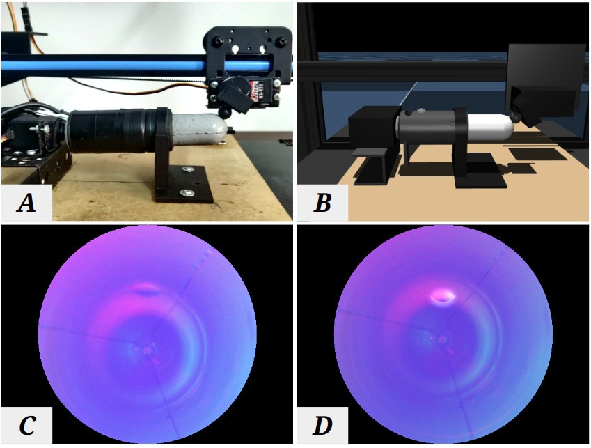
To evaluate our proposed method, we collect a dataset of real RGB tactile images using an improved GelTip sensor Gomes et al. [11], and corresponding synthetic depth-maps that are then used to generate synthetic RGB tactile images. As shown in Figure 1, a 3D printer was augmented with two additional servo motors to perform accurate tapping motions throughout the entire sensor surface, and the corresponding setup is implemented in the widely used simulator MuJoCo Todorov et al. [31]. Both qualitative and quantitative analyses are performed to compare the difference between real and virtual tactile images, which is as low as 3.9% on average in the Mean Absolute Error (MAE) and a similarity of 0.93 in the Structural Similarity Index Measure (SSIM). Furthermore, to demonstrate the capability of this method being applied for Sim2Real learning, a contact localisation task is carried out: The model is trained with tactile images generated by our simulation method, and is then evaluated using the real samples from the GelTip sensor.
II Related works
II-A High-resolution optical tactile sensors
The GelSight working principle has been initially proposed in Johnson and Adelson [19] as a method for reconstructing the texture and shape of contacted objects. To that purpose, three light sources are placed from opposite angles next to a transparent elastomer that is coated with an opaque reflective paint, resulting in three different shaded images of the in-contact object texture. Because of the constrained setup, a direct mapping between the observed image pixel intensities and the elastomer surface orientation can be established, enabling the surface to be reconstructed using photometric analysis. Thanks to its simple fabrication and the high-resolution of tactile images for robots to extract rich information, a wide variety of designs have been proposed to use this working principle to construct robotic tactile sensors Dong et al. [7], Lambeta et al. [20], Donlon et al. [8], Taylor et al. [30]. Most of these designs focused on miniaturising the sensor and they have been extensively investigated for various applications Cao et al. [3], Jiang et al. [15], Lee et al. [21], Jiang et al. [16], Jing et al. [18], Zhao et al. [37], Calandra et al. [2], Cao et al. [4]. However, most of them are constrained with a single flat sensing area, which limits the potential of these sensors being used in unstructured environments where unexpected contacts can occur either inside or outside of the grasp closure Gomes et al. [10]. To this end, a few designs have been recently proposed, in which a highly curved and/or domed finger-shaped surface membrane is considered instead, e.g., the GelTip sensor Gomes et al. [11, 10], the OmniTact sensor Padmanabha et al. [26] and a semi-round sensor Romero et al. [28]. GelTip and Romero et al. [28] follow the original design of the GelSight sensor Dong et al. [7], using glass spectres to guide the light through the membrane. In contrast, the OmniTact points the lights directly onto the membrane surface, which was also applied in flat sensors such as Donlon et al. [8], Lambeta et al. [20]. However, as argued and validated in Wang et al. [32], it is highly desirable to have the light travel through the membrane and tangent to the sensing surface, so as to achieve a more homogeneous light distribution and enable using methods such as Poisson surface reconstruction for reconstructing the elastomer surface.
II-B Simulation of GelSight sensors for Sim2Real learning
To save time and resources, it is desirable to develop and test robotic agents initially within a simulator before their deployment in real life. However, existing simulators lack appropriate models to simulate optical tactile sensors. To address this challenge, an approach was proposed to use a depth sensor in simulation to capture the geometry of the in-contact object and then render the obtained depth map to get a realistic tactile image for simulating GelSight sensors in Gomes et al. [9, 12], Chen et al. [5]. Some other works used OpenGL directly Wang et al. [33] or physics based light modelling Agarwal et al. [1] to simulate the GelSight sensors. However, the latter methods are constrained to simulating sensors in which the light is shone directly at the sensor’s membrane Dong et al. [7], Lambeta et al. [20], Padmanabha et al. [26], not through the membrane Dong et al. [7], Romero et al. [28], Wang et al. [32]. It is vital to have the light travel through the membrane, to ensure a homogeneous distribution of light on the membrane for better surface reconstructions, as argued in Wang et al. [32]. This has particular implications for curved sensors such as Gomes et al. [11], Romero et al. [28], as computing all the linear reflections within the curved membrane is computationally infeasible, and thus it is necessary to study the curved path through which the light travels within the membrane.
III Method
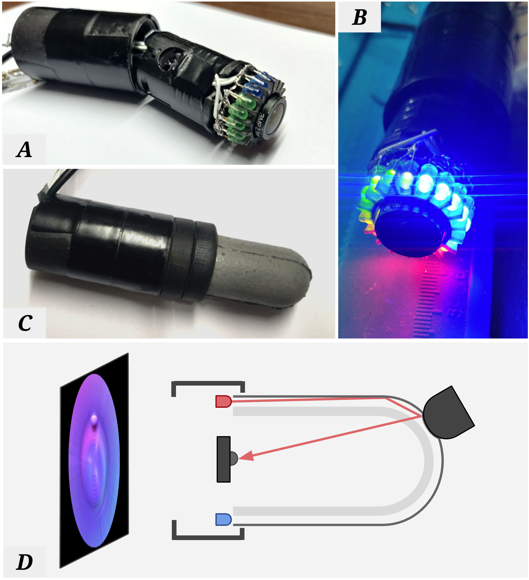
Starting from the method proposed in Gomes et al. [9, 12] for the flat GelSight sensors, additional steps are needed to address the curved geometry of the sensor and the light being guided through the curved membrane when simulating optical tactile sensors whose surface is not flat, for example the GelTip sensor as illustrated in Figure 2. In these sensors, the orthographic camera assumption is dropped, and the camera is explicitly modelled using the standard camera model. More importantly, the light directions are generalised from constants to light fields. We compute the light fields using 4 different methods that we will refer throughout the paper as Linear, Plane, Geodesic and Transport. The overall approach of simulating optical tactile sensors consists of two steps: the light fields of the sensor are first computed offline; with the computed light fields, the simulation model is then run online for each frame of the sensor simulation. The online simulation model consists of three main steps: 1) smoothing of the raw depth map, captured from the simulation environment, to mimic the elastic deformation of the real sensor; 2) mapping of the smoothed depth map onto a point-cloud in the camera coordinates frame; 3) generation of the tactile image using Phong’s illumination model and the pre-computed light fields.
III-A Offline pre-computation of light fields
A light ray emitted by a point light source to a target point in open space travels in a straight direction, , resulting in a Linear light field of radial or conical shape, or a uniform light field (of parallel rays) if is considered at the infinity. However, for some GelSight sensors such as [11, 28, 7], because the illumination sources are placed tangential to the tactile membrane, the light field travels through the membrane and assumes the sensor surface geometry. For curved sensors [11, 28], this results in a highly non-linear light field that must be computed taking into consideration the sensor’s tactile membrane geometry:
| (1) |
where is the point cloud derived from the depth map ([12] and detailed in Sub-section III-B) and is the sensor surface’s mesh description.
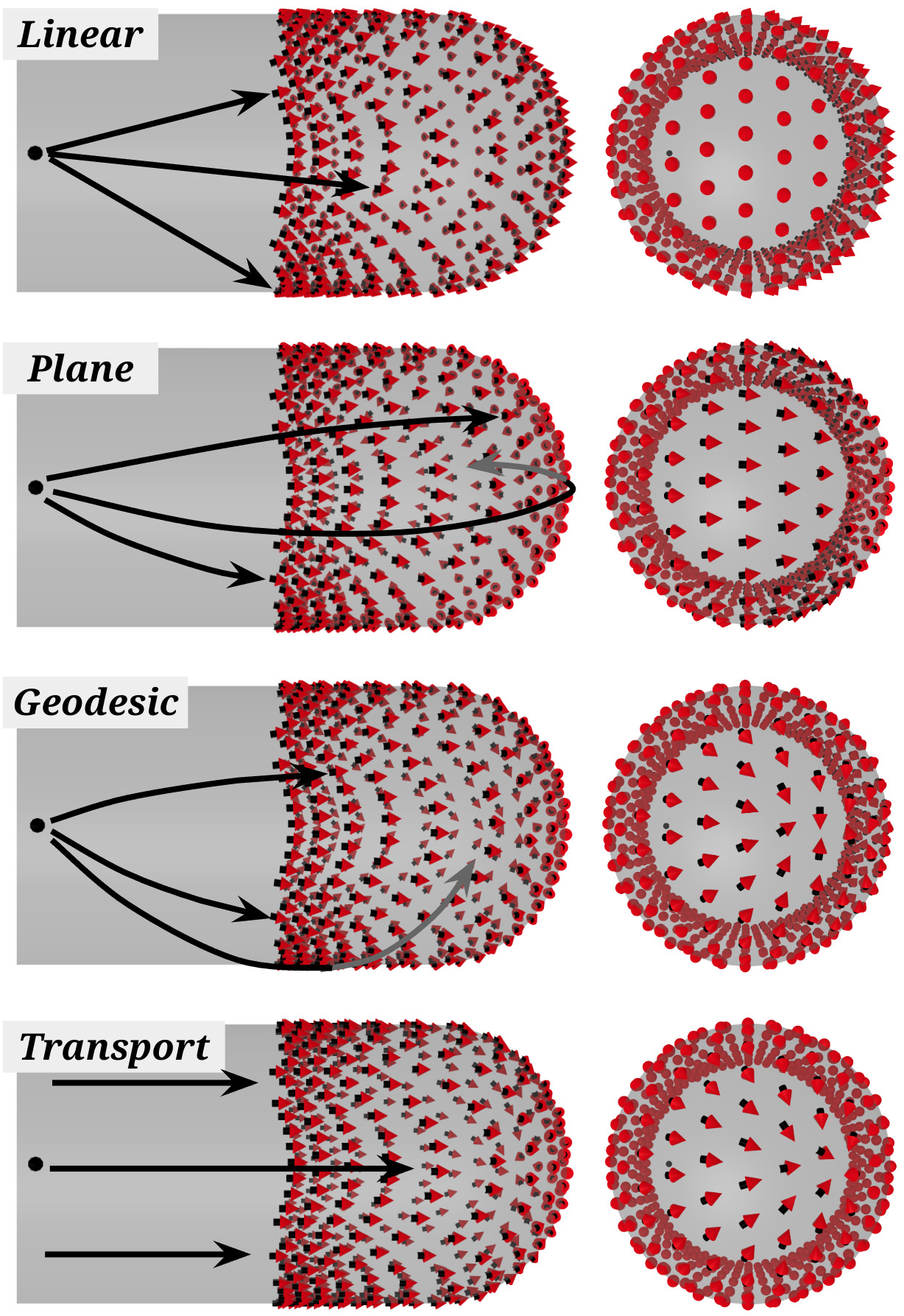
We assume that on a curved surface, the predominant ray travelling from the point light source to the target point , through the transparent elastomer, follows the corresponding shortest path possible, or geodesic that is a locally length-minimising curve. To compute such light paths from the sensor membrane mesh description, one naive approach is to intersect the mesh of the tactile membrane with a Plane that contains the light source position and the corresponding target and is orthogonal to the mesh surface on . The final sub-segment between and can then be derived and sorted, followed by extracting the final . Figure 3-A shows the resulting light fields for a single light source over the mesh using this Plane method.
A more accurate discrete Geodesic path can also be computed, using the method proposed in Mitchell et al. [25]. The algorithm works similarly to the Dijkstra shortest path algorithm for graphs, in which the distance between two neighbouring vertices is incrementally propagated through the graph. Figure 3-B shows the resulting light fields for a single light source over the mesh using this Geodesic method. However, the computation of such geodesic paths is computationally expensive and while the light travels effectively through such geodesic paths, for the illumination rendering purposes we are only concerned with the vector at the end of such paths. In other words, we are concerned with the problem of vector Transport. In Sharp et al. [29], the vector heat method was proposed, in which these vectors can be computed more efficiently via short-time heat flow, resulting in a significantly more efficient algorithm.
While the Transport method is highly more efficient than the Planes and Geodesic methods, reducing the computation time from around one and a few hours respectively, to a few minutes (considering our working parameters, mesh, depth-map resolution, parallelisation over an 8-core CPU, etc.), it is still infeasible to be run in real time for processing the light fields of each frame of the tactile images. Nonetheless, as GelSight sensors are enclosed and immune to external light variance, and that the elastomer membrane sits on top of a rigid glass, the deformations of the membrane during contacts would be insufficient to alter the overall light field, and as such we can assume that the light field stays constant. To this end, we can compute the entire light field only once, offline, and store the resulting light map for later online use.
III-B Elastomer elastic deformation approximation
While running online, a depth-map is captured from the simulation environment and its elastic deformation is approximated with a Gaussian filter, followed by an element-wise minimum operation to ensure the in-contact protrusion stays undeformed, similarly to Gomes et al. [9, 12]:
| (2) |
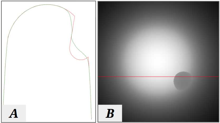
where is the depth map captured online within the simulation, is a reference depth map taken without any contact occurring and is the Gaussian kernel convolved over the difference of and . Figure 4 shows an example of the result of such operations over a profile of the depth map being contacted by a sphere object.
III-C Inverse camera projection model
The elastomer surface height map captured in the form of a depth-map is then converted into a point cloud to enable the later application of the Phong’s Illumination model Phong [27]:
| (3) |
where is the centre of the depth map ; and are given by:
| (4) |
where and are the width and height of the depth map in pixels; is the angular camera field of view in radians.
III-D Image Rendering using the Phong’s reflection model
The generation of RGB tactile images from the height-map of the elastomer (obtained from ) can be interpreted as the inverse problem of the surface reconstruction problem Johnson and Adelson [19], as the former consists of finding the mapping function while the latter . In both cases, the relationship between the two can be described by:
| (5) |
where is the reflectance function that models both the lighting conditions (i.e., illumination of the LEDs) and the reflectance properties of the surface material (i.e., the elastomer coating paint). Here, it should be noted that the colour observed at a given pixel is directly correlated with the orientation of the corresponding point on the elastomer. In Johnson and Adelson [19], the mapping of the two points in the image space and the elastomer is built through a calibration process. In our case, we get using the Phong’s illumination model Phong [27]. Phong’s model is an empirical model of local illumination that has been developed in the context of 3D Computer Graphics to describe how a given surface reflects light as a combination of the diffuse and specular reflections. From Phong’s model, observed at a given point of the sensor elastomer is given by three components: ambient, diffuse and specular light, as
| (6) |
| (7) |
where is the set of light sources (i.e., LEDs), is the emission direction of a given light source ; is the intensity of the ambient light that is not caused by any of the LEDs; and are the intensities of the diffuse and specular reflections of light source respectively; , , and are all reflectance properties of the surface; is the direction that a perfectly reflected ray of the light would take; is the direction pointing towards the camera. Given that our camera is pointing perpendicularly to the elastomer, is set to . The normalised surface normals are computed using the discrete partial derivatives of the height-map, as in the surface reconstruction Johnson and Adelson [19]:
| (8) |
where the partial derivatives and are computed using the Sobel edge detector over a point in the point cloud . Given the closed design of optical tactile sensors, and to capture unmodeled illumination, we set the background illumination to be an aligned image captured using a real sensor, when no contact is being applied to it.
IV Experimental Setup and GelTip Dataset
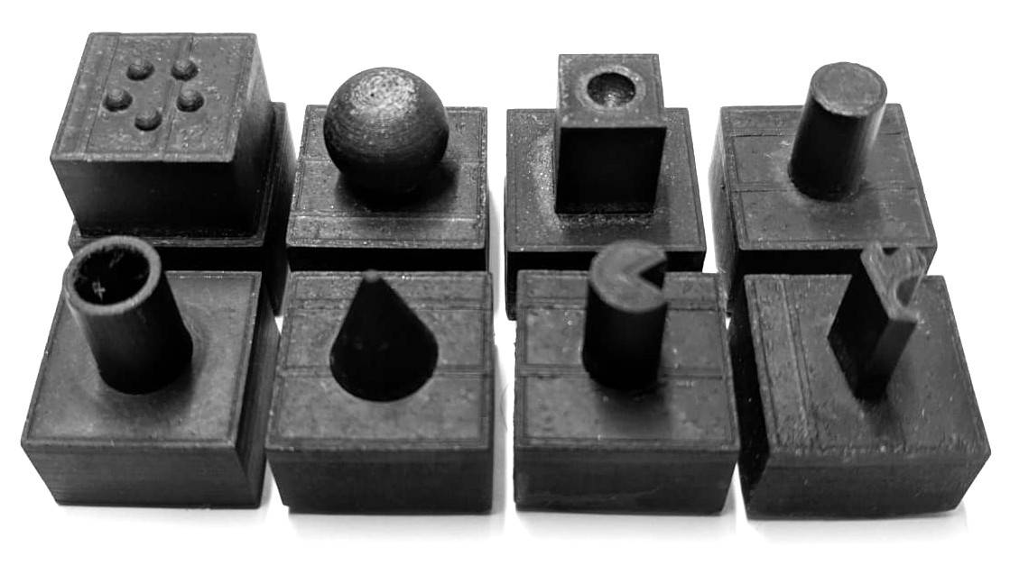
To evaluate our simulation method, we collect aligned datasets of contacts on the real and simulated GelTip sensors, by tapping 8 3D printed objects used in Gomes et al. [12], as shown in Figure 5, against the sensor. The data collection motions consist of equidistant and perpendicular taps on 3 straight paths along the longer axis of the sensor, from the tip to its base, with the sensor rotating in between each path.
In the real environment, the captured tactile images are the RGB images from the sensor camera, while in simulation, are from the depth maps in MuJoCo. Then, we experiment with the simulation model offline by setting its hyper-parameters, e.g., the different light fields, and generate the corresponding RGB synthetic tactile images. To capture the real samples, we set up a GelTip sensor on a Fused Deposition Modelling (FDM) 3D printer (Anet A30, model from Geeetech) and fix the contacting object to the printer head. Due to the curvature of the GelTip and the necessity of generating curved and downward motions normal to the sensor surface, two additional servos Hitec HS-422 are used to control the orientation of the tactile sensor () and of the contacting object (). The printer is controlled by issuing G-code commands through serial communication. Similarly, the servos are controlled using an Arduino Mega 2560 board. When setting up the simulation in MuJoCo, the parameters to take into consideration are the visual map and attributes that set the minimum and maximum depths of the OpenGL projection clipping planes, as well as the camera’s Field of View (FoV). plane is carefully adjusted to ensure that the GelTip membrane is entirely rendered. Further, and values must be later used to un-normalise the initially normalised depth map provided by the MuJoCo API following:
| (9) |
The simulation depth maps and real tactile images, are manually aligned by visually finding the transform that produces highest overlapping between real and simulated contacts.
To compute the light fields, a reference depth map (with no contacts) is captured from the simulator and converted into a point cloud. This point cloud is then used to align the sensor elastomer mesh (that was used to construct the real and simulated sensors). Finally, the light fields are computed. The Linear light field is computed straightforward as , where is a point on the sensor surface and is the position of the light source. The Plane field is computed using the Python library trimesh111https://pypi.org/project/trimesh/ for solving the plane-mesh intersection, followed by a heuristic algorithm to extract the vector at the target point, as described in Section III-A. The Geodesic field is computed using pygeodesic222https://pypi.org/project/pygeodesic/ and the Transport using the transport vector method from potpourri3d333https://pypi.org/project/potpourri3d/. These real and simulated datasets, together with object STL files, and source-code can be found on our project website.
| MAE | SSIM | PSNR | MAE | SSIM | PSNR | MAE | SSIM | PSNR | |
|---|---|---|---|---|---|---|---|---|---|
| no background | solid background | real background | |||||||
| Linear | % | % | % | ||||||
| Plane | % | % | % | ||||||
| Geodesic | % | % | % | ||||||
| Transport | % | ||||||||
V Experiments
In this section we evaluate our method by firstly analysing and comparing the synthetic datasets generated using the different light fields, secondly demonstrating the usage of the synthetic dataset to pre-train a neural network in Sim2Real tasks and, finally, illustrating the application of the proposed simulation model to explore possible future sensor designs.
V-A Quantitative and qualitative comparison of the light fields
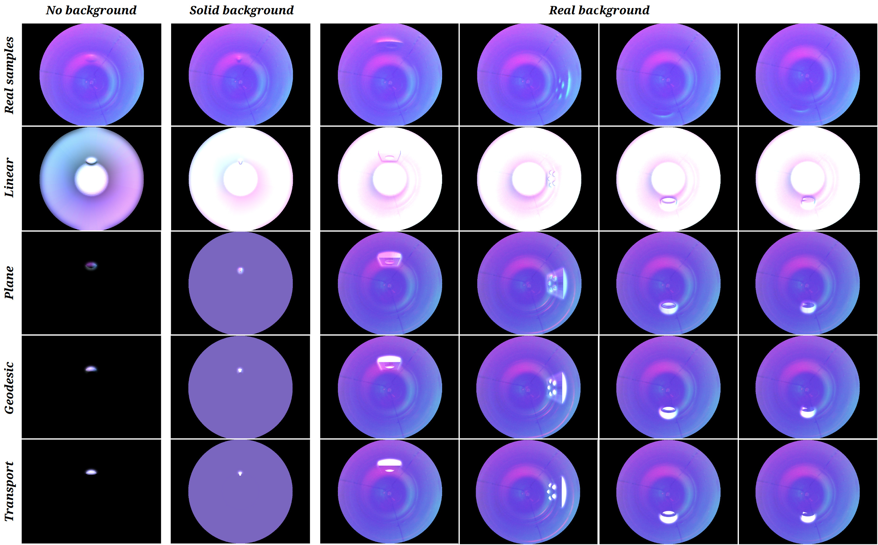
To assess the four different light fields, we generate the corresponding version of the dataset, from the captured depth maps in simulation, and quantify how similar the generated tactile images are, when compared against the real correspondences, by computing the Mean Absolute Error (MAE), Structural Similarity (SSIM) Z. Wang et al. [36] and Peak Signal-to-Noise Ratio (PSNR) over the entire dataset for the different scenarios. As reported in Table I, the Linear light field results in better MAE and SSIM of % and , when no ambient light is considered. However, if either a solid ambient illumination, or the background image from the real sensor is used, then the Plane, Geodesic and Transport methods produce better results, with a small MAE of % and a high SSIM of . This directly comes from the fact that the Plane, Geodesic and Transport methods do not produce any illumination in areas that are not being deformed by a contact, which contrasts with the Linear method that generates bright gradients throughout the entire sensor surface. This occurs because when no ambient light is considered, , and where no contacts are happening, with the light travelling tangent through the surface, , and the entire Phong’s illumination expression is zero. This happens by design and follows directly from the GelSight working principle Johnson and Adelson [19].
However, when compared against the real tactile images, we find that in practice much light travels linearly from the light sources through the membrane core, due to the sub-optimal construction of the GelTip membrane. As shown in the examples with a real background image in Figure 6, this results in the highly bright and colourful gradients in areas without any contacts and contrasting to an ideal lighting that would only travel through the elastomer membrane. Nonetheless, the Linear light field results in a highly bright tip of the sensor, which heavily contrasts with the more homogeneous (or even darker) tip observed in the real images. These gradients in areas of no contact can also be observed in flat GelSight sensors, due to their imperfect construction. In the flat GelSight simulation method Gomes et al. [12], this issue was addressed by using a real tactile image as background illumination, which is captured when no contact is occurring. Here, because the non-linear fields are tangent to the elastomer surface, we can use the same approach, as shown in Figure 6.
V-B Sim2Real transfer of contact perception
To evaluate the Sim2Real transfer of models optimised using the synthetic tactile images we experiment with contact localisation and classification. To this end, the real and simulation RGB datasets are split into equal training (80%) and validation (20%) splits, and then a ResNet from He et al. [13][24] is trained and evaluated using either simulated or real data to investigate how the models trained in simulation will perform on the real data, compared to the performance of evaluating the performance of the trained model in its own domain. Specifically, we have three different scenarios: Real2Real (R2R), Sim2Sim (S2S) and Sim2Real (S2R).
In all scenarios the network is trained with random batches of 64 images, 8 batches per epoch, for 100 epochs, using Adadelta, a learning rate of 0.1 and the mean squared error loss. The dataset computed with the Plane light field and real background image is used for the simulation data. Further, to fully exploit the advantage of simulation, and given the small Base real/sim datasets of images, an Extended simulated dataset is also collected, using the same simulation model configuration, in which the number of rows is increased to 5, the contacts per row to 16, and apply small transformations to the sensor and indenter are applied, resulting in a dataset of synthetic images. For the classification task, we also experiment with cropping centred patches around the in-contact areas. For the localisation task, the errors reported in millimetres are computed using the camera model to project the predictions of the network in the image space to points in the camera coordinates, as in Gomes et al. [11].
As reported in Tables II and III, in general, performing these tasks with the simulated images, Sim2Sim, results in significantly better results than the corresponding Real2Real cases. With the model achieving the overall highest accuracy of in the classification task, and the lowest contact localisation error of . In contrast, in the Real2Real scenario the model achieves only accuracy and a localisation error of . One possible reason could be that with the real sensor, the contact forces between the in-contact object and the sensor, results in some bending of the sensor membrane and consecutive weaker imprints, as noticeable in the examples shown in Figure 6. On the other hand, while the Extended dataset and cropping of centred patches positively contribute to a reduction in the Sim2Real gap, the Sim2Real gap is still significant: with the model trained with the simulated data achieving only a maximum classification accuracy of , in the classification task, versus the obtained by the model trained with the real data. In the Sim2Real contact localisation, the model obtains a minimum localisation error of , worse than the obtained the model trained with real data. Future research could address this Sim2Real gap, as in Jianu et al. [17].
| Base | Extended | Base | Extended | |
|---|---|---|---|---|
| Full Image | Cropped Patch | |||
| R2R | - | - | ||
| S2S | ||||
| S2R | ||||
| Base | Extended | |
|---|---|---|
| R2R | - | |
| S2S | ||
| S2R |
V-C Application to non-existing sensor designs
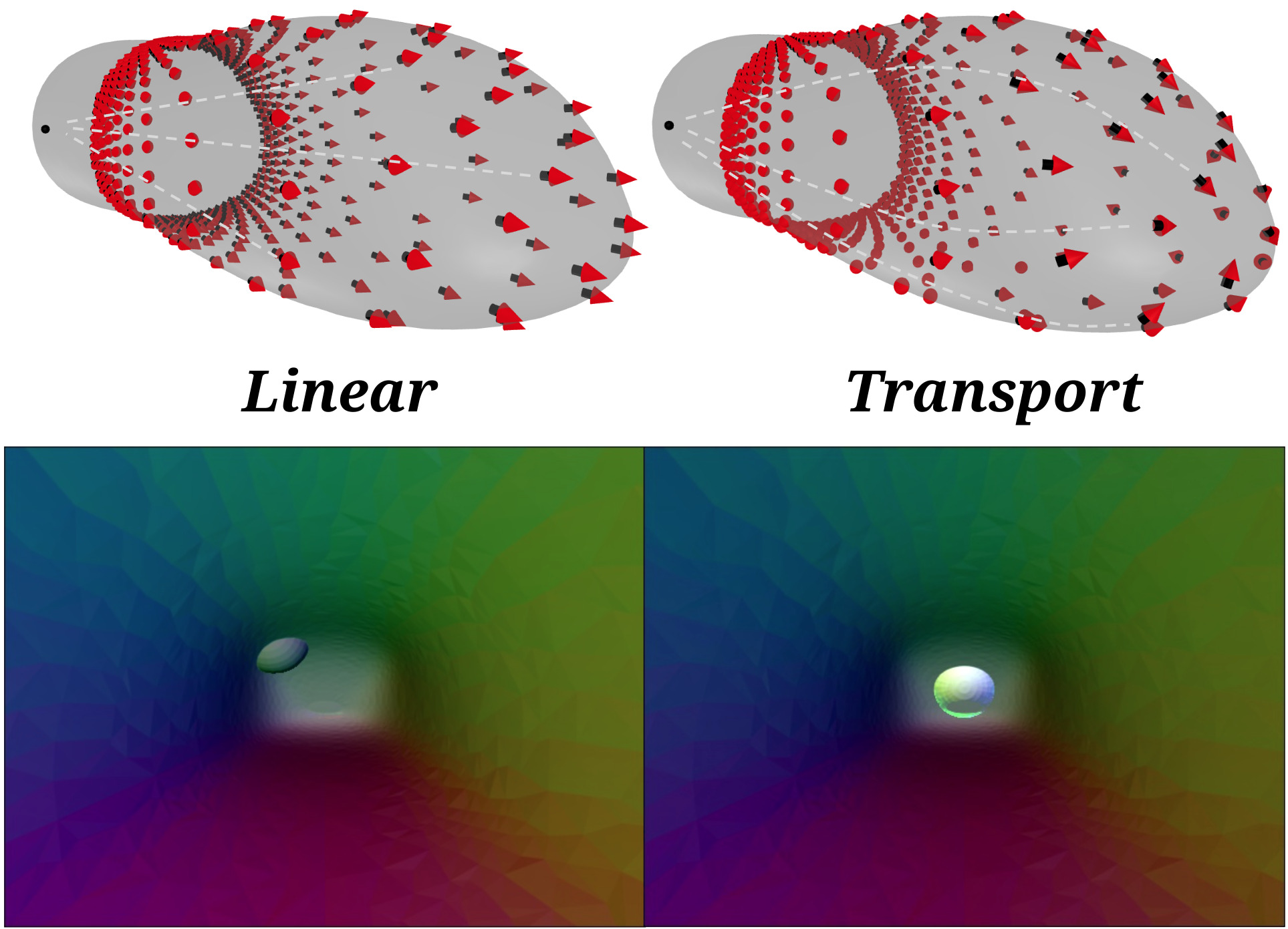
With the exception of the real background image, the proposed model only depends on the sensor’s mesh description and light sources parameters. Hence, it can be applied to explore future sensor morphologies, before their fabrication. To demonstrate this application, we design an irregular shaped membrane inspired by the human finger, and apply the proposed simulation model to it. As shown in Figure 7, the Linear and Transport light fields are rendered with the sensor being contacted by a sphere, and two tactile images are created in simulation using the the Linear and Transport light fields respectively. Since no real sensor exists to capture the real background image, an image generated using the Linear light field is used to create the ambient illumination for the Transport field. We can find that the Transport method generates more realistic light paths, especially at the tip of the finger. This example shows that the simulated tactile sensor of different morphologies could be experimented to optimise its morphology for a given task. For example, for a given grasping task, the optimal morphology of the optical tactile sensor could be obtained in the simulation using our proposed simulation model.
VI Conclusion
In this paper, we proposed a novel approach for simulating GelSight sensors of complex geometry, such as the GelTip. The development of the simulation models enables to more rapidly prototype optical tactile sensors with low cost, which is an advantage for all kinds of research using optical tactile sensors. A second benefit of our proposed method is that it enables rapid design of new sensor geometries and also evolutionary designs for specific applications. Finally, the specific considerations of the light trajectories within the tactile membrane help us in better verify whether our assumptions about the real sensor are true. For instance, with the analysis of different types of light fields, we verify that tactile images captured by the existing GelTip sensors contain a high degree of light that does not travel parallel to the sensor surface, as idealised by the early GelSight working principle Johnson and Adelson [19].
From a different perspective, we can understand the tactile image illumination as resulting from multiple reflections and phenomena. By simulating the component that travels through the membrane and only affects the deformed areas, it enabled us to construct a simulation that can take advantage of the real background image, and thus result in a highly realistic simulation, as demonstrated by our quantitative results. Furthermore, the proposed method not only unlocks simulating existing optical tactile sensors of complex morphologies, but also enables experimenting with sensors of novel morphologies, before the fabrication of the real sensor.
In the future, we will compare the tactile images obtained from a real sensor fabricated using the morphology design optimised in the simulation, and also apply our proposed simulation model in Sim2Real learning for tasks like robot grasping and manipulation with optical tactile sensing.
References
- Agarwal et al. [2021] Arpit Agarwal, Timothy Man, and Wenzhen Yuan. Simulation of vision-based tactile sensors using physics based rendering. In IEEE ICRA, 2021.
- Calandra et al. [2018] Roberto Calandra, Andrew Owens, Dinesh Jayaraman, Justin Lin, Wenzhen Yuan, Jitendra Malik, Edward H Adelson, and Sergey Levine. More than a feeling: Learning to grasp and regrasp using vision and touch. IEEE RA-L, 3(4):3300–3307, 2018.
- Cao et al. [2020] Guanqun Cao, Yi Zhou, Danushka Bollegala, and Shan Luo. Spatio-temporal Attention Model for Tactile Texture Recognition. In IEEE IROS, pages 9896–9902, 2020.
- Cao et al. [2023] Guanqun Cao, Jiaqi Jiang, Ningtao Mao, Danushka Bollegala, Min Li, and Shan Luo. Vis2hap: Vision-based haptic rendering by cross-modal generation. In ICRA, 2023.
- Chen et al. [2023] Zixi Chen, Shixin Zhang, Shan Luo, Fuchun Sun, and Bin Fang. Tacchi: A pluggable and low computational cost elastomer deformation simulator for optical tactile sensors. IEEE RA-L, 2023.
- Dahiya et al. [2009] Ravinder S Dahiya, Giorgio Metta, Maurizio Valle, and Giulio Sandini. Tactile Sensing—From Humans to Humanoids. IEEE T-RO, 26(1):1–20, 2009.
- Dong et al. [2017] Siyuan Dong, Wenzhen Yuan, and Edward H Adelson. Improved gelsight tactile sensor for measuring geometry and slip. In IEEE/RSJ IROS, pages 137–144, 2017.
- Donlon et al. [2018] Elliott Donlon, Siyuan Dong, Melody Liu, Jianhua Li, Edward Adelson, and Alberto Rodriguez. GelSlim: A high-resolution, compact, robust, and calibrated tactile-sensing finger. In IEEE/RSJ IROS, 2018.
- [9] Daniel Fernandes Gomes, Achu Wilson, and Shan Luo. Gelsight simulation for sim2real learning. In ICRA 2020 ViTac Workshop.
- Gomes et al. [2020a] Daniel Fernandes Gomes, Zhonglin Lin, and Shan Luo. Blocks world of touch: Exploiting the advantages of all-around finger sensing in robot grasping. Frontiers in Robotics and AI, 7:127, 2020a.
- Gomes et al. [2020b] Daniel Fernandes Gomes, Zhonglin Lin, and Shan Luo. Geltip: A finger-shaped optical tactile sensor for robotic manipulation. In IROS/RSJ, 2020b.
- Gomes et al. [2021] Daniel Fernandes Gomes, Paolo Paoletti, and Shan Luo. Generation of GelSight Tactile Images for Sim2Real Learning. IEEE RA-L, 6(2):4177–4184, 2021.
- He et al. [2015] Kaiming He, Xiangyu Zhang, Shaoqing Ren, and Jian Sun. Deep residual learning for image recognition. CVPR, 2015.
- Hogan et al. [2021] Francois R. Hogan, Michael Jenkin, Sahand Rezaei-Shoshtari, Yogesh Girdhar, David Meger, and Gregory Dudek. Seeing through your skin: Recognizing objects with a novel visuotactile sensor. In Proceedings of the IEEE/CVF Winter Conference on Applications of Computer Vision (WACV), pages 1218–1227, January 2021.
- Jiang et al. [2021] Jiaqi Jiang, Guanqun Cao, Daniel Fernandes Gomes, and Shan Luo. Vision-guided active tactile perception for crack detection and reconstruction. In 29th Mediterranean Conference on Control and Automation (MED), pages 930–936, 2021.
- Jiang et al. [2022] Jiaqi Jiang, Guanqun Cao, Aaron Butterworth, Thanh-Toan Do, and Shan Luo. Where shall i touch? vision-guided tactile poking for transparent object grasping. IEEE/ASME Transactions on Mechatronics, 2022.
- Jianu et al. [2022] Tudor Jianu, Daniel Fernandes Gomes, and Shan Luo. Reducing tactile sim2real domain gaps via deep texture generation networks. In IEEE ICRA, pages 8305–8311, 2022.
- Jing et al. [2023] Xingshuo Jing, Kun Qian, Tudor Jianu, and Shan Luo. Unsupervised adversarial domain adaptation for sim-to-real transfer of tactile images. IEEE Transactions on Instrumentation and Measurement, 2023.
- Johnson and Adelson [2009] Micah K Johnson and Edward H Adelson. Retrographic sensing for the measurement of surface texture and shape Retrographic sensing for the measurement of surface texture and shape. In IEEE CVPR, 2009.
- Lambeta et al. [2020] Mike Lambeta, Po-Wei Chou, Stephen Tian, Brian Yang, Benjamin Maloon, Victoria Rose Most, Dave Stroud, Raymond Santos, Ahmad Byagowi, Gregg Kammerer, et al. DIGIT: A novel design for a low-cost compact high-resolution tactile sensor with application to in-hand manipulation. IEEE RA-L, 5(3):3838–3845, 2020.
- Lee et al. [2019] Jet-Tsyn Lee, Danushka Bollegala, and Shan Luo. “touching to see” and “seeing to feel”: Robotic cross-modal sensory data generation for visual-tactile perception. In ICRA, pages 4276–4282. IEEE, 2019.
- Li et al. [2020] Qiang Li, Oliver Kroemer, Zhe Su, Filipe Fernandes Veiga, Mohsen Kaboli, and Helge Joachim Ritter. A review of tactile information: Perception and action through touch. IEEE T-RO, 36(6):1619–1634, 2020.
- Luo et al. [2017] Shan Luo, Joao Bimbo, Ravinder Dahiya, and Hongbin Liu. Robotic Tactile Perception of Object Properties: A Review. Mechatronics, 48:54–67, 12 2017.
- maintainers and contributors [2016] TorchVision maintainers and contributors. Torchvision: Pytorch’s computer vision library, 2016.
- Mitchell et al. [1987] Joseph S. B. Mitchell, David M. Mount, and Christos H. Papadimitriou. The discrete geodesic problem. SIAM J. Comput., 16:647–668, 1987.
- Padmanabha et al. [2020] Akhil Padmanabha, Frederik Ebert, Stephen Tian, Roberto Calandra, Chelsea Finn, and Sergey Levine. Omnitact: A multi-directional high-resolution touch sensor. In IEEE ICRA, pages 618–624, 2020.
- Phong [1975] Bui Tuong Phong. Illumination for computer generated pictures. ACM Commun., 1975.
- Romero et al. [2020] Branden Romero, Filipe Veiga, and Edward Adelson. Soft, round, high resolution tactile fingertip sensors for dexterous robotic manipulation. In IEEE ICRA, pages 4796–4802, 2020.
- Sharp et al. [2019] Nicholas Sharp, Yousuf Soliman, and Keenan Crane. The vector heat method. ACM Trans. Graph., 38(3), 2019.
- Taylor et al. [2022] Ian H Taylor, Siyuan Dong, and Alberto Rodriguez. GelSlim 3.0: High-resolution measurement of shape, force and slip in a compact tactile-sensing finger. In IEEE ICRA, pages 10781–10787, 2022.
- Todorov et al. [2012] Emanuel Todorov, Tom Erez, and Yuval Tassa. Mujoco: A physics engine for model-based control. In 2012 IEEE/RSJ IROS, pages 5026–5033, 2012. doi: 10.1109/IROS.2012.6386109.
- Wang et al. [2021] Shaoxiong Wang, Yu She, Branden Romero, and Edward H Adelson. GelSight Wedge: Measuring High-Resolution 3D Contact Geometry with a Compact Robot Finger. In ICRA, 2021.
- Wang et al. [2022] Shaoxiong Wang, Mike Lambeta, Po-Wei Chou, and Roberto Calandra. TACTO: A fast, flexible and open-source simulator for high-resolution vision-based tactile sensors. IEEE Robotics and Automation Letters, 7(2), 2022.
- Ward-Cherrier et al. [2018] Benjamin Ward-Cherrier, Nicholas Pestell, Luke Cramphorn, Benjamin Winstone, Maria Elena Giannaccini, Jonathan Rossiter, and Nathan F. Lepora. The TacTip Family: Soft Optical Tactile Sensors with 3D-Printed Biomimetic Morphologies. Soft Robotics, 5(2):216–227, 2018.
- Yuan et al. [2017] Wenzhen Yuan, Siyuan Dong, and Edward H. Adelson. Gelsight: High-resolution robot tactile sensors for estimating geometry and force. Sensors, 17(12), 2017.
- Z. Wang et al. [2004] Z. Wang, A.C. Bovik, H.R. Sheikh, and E.P. Simoncelli. Image quality assessment: from error visibility to structural similarity. TIP, 2004.
- Zhao et al. [2023] Yongqiang Zhao, Xingshuo Jing, Kun Qian, Daniel Fernandes Gomes, and Shan Luo. Skill generalization of tubular object manipulation with tactile sensing and sim2real learning. Robotics and Autonomous Systems, 160:104321, 2023.