Atomic Anatomy of Low-Inertia Power Systems
Abstract
In this article, we determine a fundamental anatomical modeling parallelism between low-inertia power systems and Bohr’s atomic model. The proposed atomic architecture will serve as a microscopic building block, where we validate the structural analogy of low-inertia power systems using semi-classical quantum approximations in IEEE 9-bus & 39-bus systems. As a future scope of work, detailed modeling & system stability will be investigated by using pre-quantization and geometric quantization methods.
Index Terms:
Low-inertia power systems, Bohr model, Semi-classical models, Power system stability, Power systems modeling.I Introduction
Inertia in power systems is usually governed by the inherent rotational mass in synchronous machines (SM) [1]. From a system perspective, converter-interfaced generation (CIG) that allow integration of renewable energy sources behave quite differently from SM. Apart from their intermittent nature, CIG without any stored kinetic energy do not implicitly contribute to the system inertia due to electrical decoupling. With increased penetration of power from renewable energy sources and the current decarbonization goals, the future power system is highly prone to frequency instability.
From a curiosity-driven research viewpoint, this article proposes a fundamentally new anatomical modeling parallelism between the low-inertia power systems and Bohr’s atomic model by hypothesizing a structural duality of the system with respect to different components in the smallest fundamental particle, i.e., an atom. A transformative understanding to model future power systems as an atom will not only unravel generation of better set-points for reduced numerical computational efforts to assess the system stability, but will also serve as a building block based planning tool to encompass power system expansion and integration in the future only using inter-atomic physical interactions. We argue against the single mass model of power systems that represent frequency as a global parameter by splitting it spatially into the rotational inertia in SM and virtual inertia in CIG [2] (commonly known as virtual synchronous generators (VSGs)) of the future power systems into different atomic components as per Bohr’s prophecy. Finally, we validate the proposed structural duality based on the center-of-mass theory and semi-classical quantum approximations in Bohr’s model.
II The Bohr Atomic Model
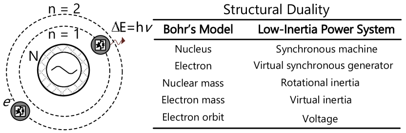
Proposed by Niels Bohr in his paper “On the Constitution of Atoms and Molecules”[3] in 1913, the Bohr atomic model is a structural representation of a hydrogen atom consisting of a nucleus made up of a single proton, and an orbiting electron, as shown in Fig. 1. The model is best summarized by three fundamental postulates:
-
1.
As opposed to the classical theory of electromagnetism, electron(s) can be located at certain stable orbits, known as stationary orbits, without either absorbing or emitting any energy.
-
2.
These stationary orbits are attained at discrete distance from the nucleus. Specifically, orbits are attained at precise, unchangeable radii, wherein the angular momentum of the orbiting electron is an integer multiple of the reduced Planck constant, in the quantization equation, , where is the principal quantum number and describes the energy level of the electron.
-
3.
Electrons can only interact using electromagnetic radiation by jumping from one orbit to another. An electron can jump to a higher energy level by absorbing a photon, and can jump to a lower energy level by emitting a photon. The energy of these photons is determined as the difference between the energies of the two orbits, which by the Planck relation gives , where and are the energies of the final and initial orbits, respectively. Furthermore, is the Planck constant, and is the frequency of the photon.
Remark I: The energy dissipation/absorption in Bohr’s model is a spatial phenomena with its bounded orbital radius scattered around the nucleus.
III Structural Duality
III-A Mass Identification in Systems & Converters
With system frequency considered as a global parameter, the SMs can be aggregated into a single-mass model with its rotor dynamics given by:
| (1) |
where, is the electric angle of the SM. Further, and are mechanical and electrical power, respectively, with being the synchronous speed. Lastly, is the normalized inertia constant, where is the moment of inertia and is the rated power of SM.
| 1. Case study with 1 VSG & 2 SMs |
| Case | VSG | Va, Pb | SM1 | V, P | SM2 | V, P |
|---|---|---|---|---|---|---|
| Case I | #2* | 1.006,140 | #3 | 0.997,170 | #1 | 0.993,170 |
| Case II | #6 | 0.984,133 | #3 | 0.971,174 | #1 | 0.976,174 |
| Case III | #1 | 0.983,127 | #2 | 0.963,172 | #3 | 0.963,172 |
| 2. Case study with 2 VSGs & 1 SM |
| Case | VSG1 | V, P | VSG2 | V, P | SM | V, P |
|---|---|---|---|---|---|---|
| Case IV | #1 | 1,156 | #2 | 0.996,125 | #3 | 1.03,212 |
| Case V | #3 | 1.004,152 | #2 | 1.001,121 | #1 | 0.979,214 |
∗ denote the bus number, a is normalized and in p.u., b is stated in MW.
| #30* | Va, Pb | #37 | V, P | #35 | V, P | #38 | V, P | #32 | V, P | #34 | V, P | #33 | V, P | #36 | V, P |
|---|---|---|---|---|---|---|---|---|---|---|---|---|---|---|---|
| SG1 | 1.075,2.36 | SG2 | 1.075,2.58 | SG3 | 1.077,3.4 | SG4 | 1.079,3.6 | SG5 | 1.07,0.4 | SG6 | 1.077,4.1 | SG7 | 1.07,4.4 | SG8 | 1.079,3.6 |
| SG1 | 1.04,2.32 | SG2 | 1.04,2.6 | SG3 | 1.03,3.7 | SG4 | 1.03,3.9 | VSG1 | 0.95,0.3 | VSG2 | 1.07,3.6 | VSG3 | 1.07,4.3 | SG8 | 1.04,3.5 |
∗ denote the bus number, a is normalized and in p.u., b is stated in MW.
For a solid cylinder rotating about an axis (such as a rotor shaft in SM), the moment of inertia , where and denote the mass and radius of the cylinder, respectively. Hence, a higher mass not only contributes to a higher moment of inertia, but also naturally align to a smaller change in frequency during contingencies. On the other hand, VSGs do not have any inherent physical mass, and thus do not benefit from natural storage of kinetic energy. However, the maximum amount of energy stored in its DC capacitor, given by with being the DC capacitance and being the DC voltage across it, is programmed to provide virtual inertial response similar to the mechanical inertia.
Remark II: Comparing the expressions for moment of inertia and stored energy in capacitors (with as the equivalent mass in VSGs), an important disparity is the scale of the characteristic mass between SMs & VSGs with .
Corollary I: Using the mass disparity in Remark II, single mass of the system can be visualized as the nucleus in Bohr’s model, which accounts for majority of the atomic mass, whereas the electrons (analogous to the VSGs) orbiting around it signify negligible system mass .
III-B Center of Mass for Particle Systems
Considering each SM in power systems as a particle, we will then have distributed mass corresponding to the rotor of each SM.
Hypothesis: In low-inertia power systems with distributed mass, the center of mass can represent the position of the atomic nucleus, and consequently, can attribute the position of orbits around it.
In that regard, we consider a very naive approach of a system of particles with , where the particles have mass , and are located in a space with coordinates . Finally, the coordinates for the center of mass , satisfy:
| (2) |
We can obtain simply by isolating:
| (3) |
where, is the total mass of the system.
Remark III: The typical definition of in Bohr’s model does not necessarily extend to low-inertia power systems since the former caters to a spatial phenomena, where the activation energy required by an electron to jump from one orbit to another can be absorbed/dissipated anywhere in the space. On the contrary, energy dissipation in power systems is only possible across the transmission lines, which necessitates a viable definition of in low-inertia power systems.
Conferring on key structural parallelism to this end, a close representation of the atomic anatomy of low-inertia power systems can be seen in Fig. 1. However, there are still some unresolved questions:
-
1.
How can the structural duality of the orbits in Bohr’s model (in Fig. 1) be extended to low-inertia power systems?
-
2.
With increased penetration from CIGs, from SMs will be sequentially depleted that will then displace the space coordinates of the center of mass . How will this displacement affect a shift in the coordinates of the orbits around it?
We will now test our hypothesis and answer the abovementioned queries using different case studies of penetration from multiple VSGs and SMs to validate the anatomical modeling co-relationship in the next section.
IV Structural Validation
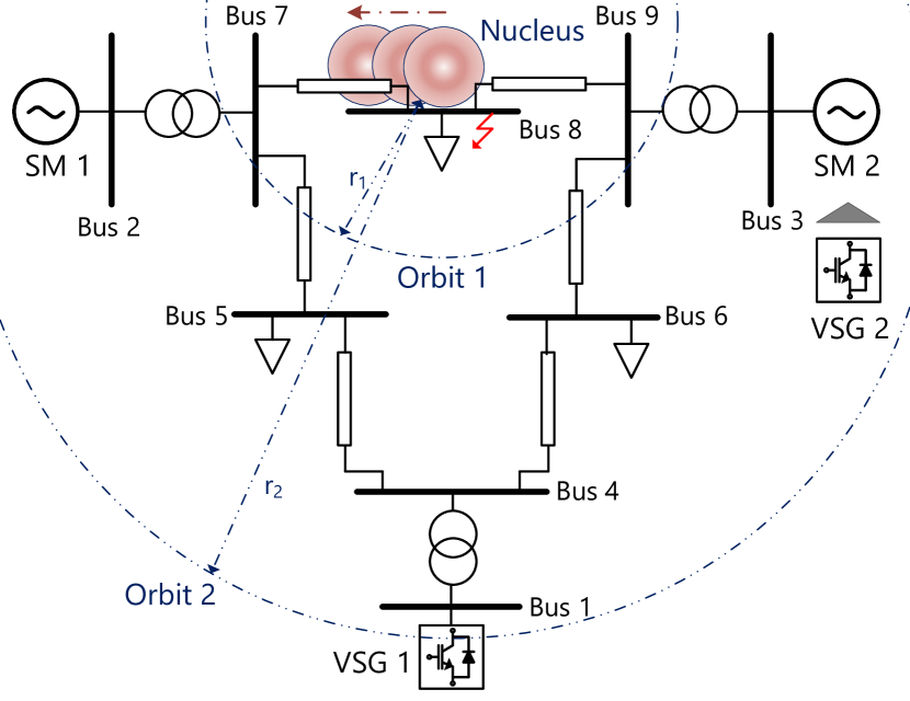
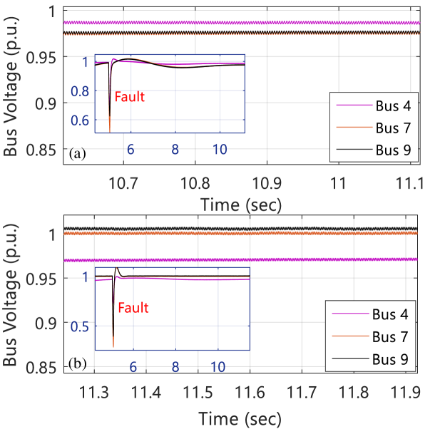
To validate the structural analogy, we consider different combinations of VSGs and SMs in IEEE 9-bus & 39-bus systems using PSCAD simulation environment. For IEEE 9-bus system with 3 generators, we consider two case studies in Table I with: 1) 1 VSG and 2 SMs, and 2) 2 VSGs and 1 SM. As shown in Fig. 2, the center of mass is located at the center due to the placement of SM 1 and SM 2 at both ends (Refer to Case I in Table I). In Case I after the clearance of the fault in bus 8, it can be observed that the corresponding voltages across the buses (Bus 3 & 1) with SM are attained at a discrete difference from the bus (Bus 2) with VSG. Furthermore, the quantization of the difference can also be seen in the power generation from each bus. It should be worthy notifying that the voltage difference between both the SM buses in Case I-III (in Table I) is expected to be within a tolerable range of 0.005 p.u in a distributed particle system. In Case II, when VSG1 is integrated into bus 6, a similar pattern is observed where its bus voltage and power is attained at a discrete difference of large quantum numbers from bus 1 & 3. A time-domain simulation result corresponding to Case II is also shown in Fig. 3(a) after the fault is cleared. In Case III, the placement of generators are shuffled with SMs integrated into bus 2 and 3 and VSG in bus 1. Although this changes the coordinates of the center of mass , similar behavior is observed with the difference in bus voltages and generated power.
Corollary II: From the discussion above with SMs and VSG representing the nucleus and electrons respectively, terminal voltages can be adjudged as the structural duality of orbits in low-inertia power systems for absorption/dissipation of a given activation energy .
Another equivalent valid interpretation of this corollary is that quantum theory must agree with classical mechanics while accounting using semi-classical quantum approximations [4]. Not only corollary II formalizes corollary I, the behavior as a callback to Bohr’s second postulate can be validated from all the case studies in Table I and II.
As shown in Fig. 2, when the number of VSGs are increased (with VSG 2 replaced with SM 2 in bus 3), the center of mass is displaced towards the bus closest to SM 1 as per corollary I with a significant reduction in system mass. However, following from the cases I-V in Table I, the difference of voltages across SM and VSG is not consistent due to different activation energies. Using Remark III and corollary II, we can conclude that a viable definition of in low-inertia power systems can be the equivalent electrical impedance between the bus representing the nucleus (SM, as per corollary I) and the orbits with electrons (VSGs). In IEEE 9-bus system, this can be validated using case IV (see Fig. 3(b)) & V, wherein the placement of SM and VSGs are shuffled by integrating them into different buses. Although they are aligned with corollary II, the electrical radius affects their corresponding voltage profiles.
Corollary III: The radius in the atomic model corresponds to the equivalent electrical impedance between the buses representing the nucleus and orbits. In short, they are analogous to the quantization levels for different orbits.
It not only aligns with Bohr’s third postulate, but also answers the energy dissipation theory in the atomic model along electrical path for power systems, corresponding to Remark III. To generalize the abovementioned corollaries, these tests have also been performed in IEEE 39-bus system after the fault is cleared in bus 16. From Table II, it can be seen that all the corollaries corresponding to the Bohr’s postulates are aligned to validate the atomic model of future power systems.
V Conclusions and Future Scope of Work
This article determines a fundamental atomic model with clearly defined structural corollaries between Bohr’s model and low-inertia power systems. With the preliminary anatomical model intact, we aim to explore a detailed modeling framework and stability using pre-quantization and geometric quantization methods as a future extension of this work.
References
- [1] P. Tielens and D. Van Hertem, “The relevance of inertia in power systems,” Renewable and Sustainable Energy Reviews, vol. 55, pp. 999–1009, 2016.
- [2] J. Driesen and K. Visscher, “Virtual synchronous generators,” in 2008 IEEE Power and Energy Society General Meeting - Conversion and Delivery of Electrical Energy in the 21st Century, 2008, pp. 1–3.
- [3] N. Bohr, “On the constitution of atoms and molecules,” The London, Edinburgh, and Dublin Philosophical Magazine and Journal of Science, vol. 26, no. 151, pp. 1–25, 1913.
- [4] T. Sauvaget, “Classical and semiclassical studies of the hydrogen molecule. chaotic dynamics [nlin.cd].” Ph.D. dissertation, University of Nottingham (UK), Nov. 2006.